

Page 1
HYPER-UNIFIED STORAGE
Nexsan Unity
Hardware Maintenance Guide
Firmware Version Unity v. 5.1
NEXSAN | 325 E. Hillcrest Drive, Suite #150 | Thousand Oaks, CA 91360 USA
Printed Wednesday, January 02, 2019 | www.nexsan.com
Page 2

Copyright © 2010—2018 Nexsan Technologies, Inc. All rights reserved.
Trademarks
Nexsan® is a trademark or registered trademar k of Nexsan Technologies, Inc. The Nexsan logo is a registered trademark of Nexsan Technologies, Inc.
Allother trademarks and registered trademarks are the property of their respective owners.
Patents
This pr oduct isprotected by one or more of the following patents, and other pending patent applications worldwide:
United States patents US8,191,841, US8,120,922;
United Kingdom patents GB2466535B, GB2467622B, GB2467404B, GB2296798B, GB2297636B
About this document
Unauthorized use, duplication, or modification of this document in whole or in part without the written consent of Nexsan Corporation is strictly
prohibited.
Nexsan Technologies, Inc. reserves the right to make changes to this manual, as well as the equipment and software described in this manual,
at any time without notice. This manual may contain links to Web sites that were current at the time of publication, but have since been moved
or become inactive. It may also contain links to sites owned and operated by third parties. Nexsan is not responsible for the content of any such
third-party site.
Page 3

Contents
Contents
Contents 3
Chapter 1: Customer-Replaceable Units: Class 1 9
ESD protection 10
Disk drives 11
Identifying failed disk drives 11
Data disk failures 11
FASTier disk failures 16
Replacing data disks 18
Replacing FASTier drives 22
Power supply units (PSUs) 25
Identifying failed power supply units (PSUs) 25
Replacing a standard PSU 28
Replacing a US 460 PSU 30
SFPs 33
Chapter 2: Customer Replaceable Units: Class 2 35
Unity Storage Expansion controllers 36
Identifying a failed controller 36
Check the front panel LEDs for controller errors 36
Identify the controller numbers using the CLI 37
Desc ription 37
Controller 37
Syntax 37
Options 37
Example 37
Replacing a Unity Storage Expansion controller 39
System sub-components 41
Fans 43
Replacing a fan 43
Chapter 3: Customer Replaceable Units: Class 3 53
Unity Storage System controllers 54
Replacing a Unity Storage System controller 54
Chapter 4: Support-Assisted FRUs: Class 2 57
DIMMs 58
Identifying a failed DIMM 58
Nexsan Unity www.nexsan.com 3
Page 4

Contents
Chapter 5: Support-Assisted Replacements: Class 3 59
Chassis 60
Identifying a failed chassis 60
Replacing a chassis 60
System SSDs 64
Replacing the FASTier Cache SSD 64
Replacing the OS SSD 68
Record system settings 68
Back up the old OS SSD 68
Install the new OS SSD 68
Transfer data to the new OS SSD 71
Re-enter IPMI settings 71
Replace and restore the OS SSD on the other unit 72
SATADom 72
Replacing a SATADom 72
Nexsan Unity Hardware Maintenance Guide v. 5.1 Unity 4
Page 5

About this document
This Hardware Maintenance Guide provides information and detailed procedures for the removal and
replacement of these Nexsan Unity Unity 2.0/5.0 Hardware systems:
Nexsan Unity 2200™ Storage System
Nexsan Unity 4400™ Storage System
Nexsan Unity 6900™ Storage System
Nexsan Unity 2200X™ Storage Expansion
Nexsan Unity Storage 224X™ Expansion
Nexsan Unity Storage 316X™ Expansion
Nexsan Unity Storage 424X™ Expansion
Nexsan Unity Storage 460X™ Expansion
The replacement procedures are considered either Customer-Replaceable Units (CRUs) or support-assisted
Field-Replaceable Units (FRUs). CRUs can be performed without any assistance whereas support-assisted
FRUs always require help from Nexsan Technical Support. All procedures are rated based on the associated
risk to the system should the procedure not be followed correctly. Class 1 procedures have the lowest
associated risk and Class 3 procedures have the highest associated risk. Below are the classes used in this
manual to group procedures:
CRU: Class 1
CRU: Class 2
CRU: Class 3 (highest risk)
FRU: Class 1
FRU: Class 2
FRU: Class 3 (highest risk)
Contact Nexsan Support for assistance if you identify issues with any of the following components:
HBA cards
CPUs
DIMMs
NVDIMMs
Nexsan Unity www.nexsan.com 5
Page 6
About this document
Audience
This guide has been prepared for the following audience:
Any qualified NST/Unityadministrator.
Conventions
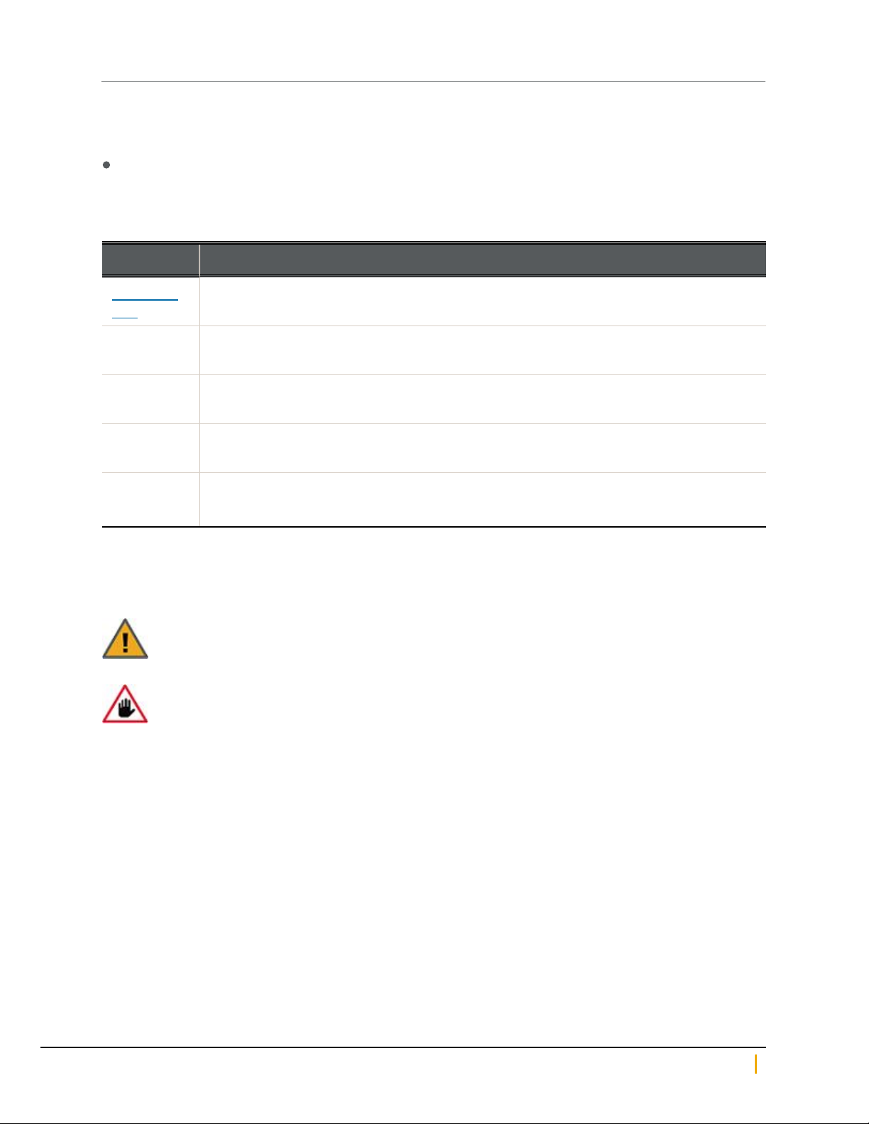
Here is a list of text conventions used in this document:
Convention Description
underlined
blue
boldface Text that refers to labels on the physical unit or interactive items in the graphical user
monospace
monospace
bold
italics System messages and non-interactive items in the graphical user interface (GUI)
Cross-references, hyperlinks, URLs, and email addresses.
interface (GUI).
Text that is displayed in the command-line interface (CLI) or text that refers to file or
directory names.
Text strings that must be entered by the user in the command-line interface or in text fields
in the graphical user interface (GUI).
References to Software User Guides
Notes, Tips, Cautions, and Warnings
Note Notes contain important information, present alternative procedures, or call attention to certain items.
Tip Tips contain handy information for end-users, such as other ways to perform an action.
CAUTION: In hardware manuals, cautions alert the user to items or situations which may cause
damage to the unit or result in mild injury to the user, or both. In software manuals, cautions alert the
user to situations which may cause data corruption or data loss.
WARNING: Warnings alert the user to items or situations which may result in severe injury
or death to the user.
Nexsan Unity Hardware Maintenance Guide v. 5.1 Unity 6
Page 7
About this document
Contacting Nexsan
For questions about Nexsan products, please visit the Nexsan support Web page, and the Nexsan Unity
Documents and Downloads page. If you are unable to find the answer to your question there, please see our
contact information below.
Service and support
Nexsan's Technical Services Group provides worldwide assistance with installation, configuration, software
support, warranty, and repair for all Nexsan products. A variety of service and support programs are available
to provide you with the level of coverage and availability your operation requires.
Nexsan Unity Documents & Downloads page:
https://helper.nexsansupport.com/unt_
downloads.html
Unity Online Help page:
https://helper.nexsansupport.com/unt_
onlinehelp.html
Contact Nexsan Unity support:
https://helper.nexsansupport.com/unt_support
Worldwide Web site:
www.nexsan.com
Related documentation
The following Nexsan product manuals contain related information:
Nexsan Unity Online Help
Nexsan Unity Hardware Reference Guide
Nexsan UnityHardware Maintenance Guide, Unity Next Generation
Nexsan Unity Software User Guide
Nexsan Unity nxadmin Command-line Interface Reference Guide
Nexsan Unity nxcmd Command-line Interface Reference Guide
Nexsan Unity Snapshots and Replication Guide
Nexsan Unity Storage Expansion Reference Guide
Nexsan Unity VMware Best Practices Guide
Nexsan Unity NFS Interoperability
Nexsan Unity Networking Best Practices Guide
Nexsan Unity Performance Best Practices Guide
Nexsan Unity Microsoft Best Practices Guide
Nexsan Unity www.nexsan.com 7
Page 8
Contents
Safety notices
Always observe the following precautions to reduce the risk of injury and equipment damage:
Computer components and disk drives are sensitive to static discharge. Take precautions to discharge
any electrostatic charge from your person before and while handling components with your hands or any
tools. Use an anti-static wrist-strap.
The system only be installed in a clean, dry environment. The operating temperature is 10º to 35º C (50º to
95º F), with operating relative humidity at 20 to 95%, non-condensing.
Do not install hardware in an enclosed cabinet or other small area without ventilation.
Ensure correct lifting methods are used when handling hardware. Special care should be taken when
removing hardware from its packaging and positioning it into its required location. When lifting hardware,
two people at either end should lift slowly with their feet spread out to distribute the weight. Always keep
your back straight and lift with your legs.
When installing the system as a rack-mounted component, ensure that all Nexsan-supplied mounting
fixtures are secure. All bolts and screws should be fully tightened. Failure to comply with this may result in
the unit not being fully supported in the rack and could lead to the product falling from the rack causing
personal injury or falling onto other rack components.
Ensure that the rack is sufficiently stable by having wall anchors and/or stabilizing legs, and that the floor
supporting the rack has sufficient strength for the overall weight loading.
Only a fully-trained Service Engineer is authorized to disassemble any other part of the hardware, and then
only when the hardware is powered off.
The system has multiple power connections; as a result, you must remove all power leads to completely
isolate the power and always use the IEC power cords which are supplied with the system.
CAUTION: All Nexsan Unity Storage Systems are hot-pluggable. However, new expansions must
be powered on AFTER you connect it to the existing system.
Nexsan Unity Hardware Maintenance Guide v. 5.1 Unity 8
Page 9

Chapter 1
Chapter 1:Customer-Replaceable Units: Class 1
Class 1 CRUs - The following components of the Nexsan Unity Storage Systems are replaceable by the
customer without assistance from Technical Support and have little associated risk of causing a complete or
partial system failure if the documented replacement procedure is followed correctly. However, if you are
unsure about a specific step or process, please contact Nexsan Support for assistance.
This chapter contains the following sections:
ESD protection 10
Disk drives 11
Power supply units (PSUs) 25
SFPs 33
1
Nexsan Unity www.nexsan.com 9
Page 10
ESD protection
ESD protection
CAUTION: Computer components and disk drives are sensitive to electrostatic discharge (ESD).
Follow all appropriate anti-static procedures to prevent damage to your equipment or components.
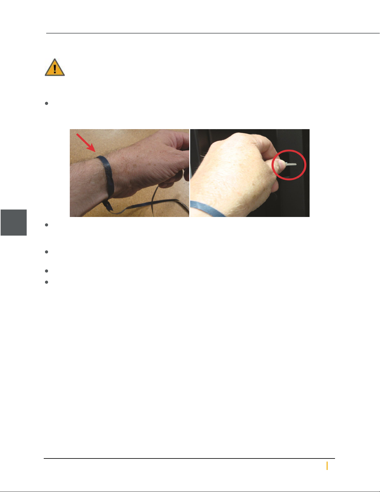
► To prevent ESD damage:
Use the anti-static wrist-strap shipped with Unity whenever you are performing maintenance on the Unity
Storage System.
Figure 1-1: Using the anti-static wrist strap
1
Before touching components with your hands or with any tools, and before removing any components from
their anti-static bags, ground any electrostatic charge from your person by touching a grounded metal
object.
Handle printed circuit boards by their edges only. Do NOT touch any of a board’s components, chips,
modules, or contacts.
When handling replaceable components, do NOT touch any exposed pins or contacts.
Place components and modules into their anti-static bags when they are not in use.
Nexsan Unity Hardware Maintenance Guide v. 5.1 Unity 10
Page 11
Chapter 1: Customer-Replaceable Units: Class 1
Disk drives
Disk drives (either data drives or FASTier drives) are mounted in drive carriers to simplify their installation and
removal from the chassis.
CAUTION: Disk drive carriers help promote proper airflow for drives. For this reason, even empty
carriers without disk drives installed MUST remain in the chassis.
Identifying failed disk drives
If a disk drive fails, the Unity Storage System software interfaces and enclosures display the appropriate
warnings.
Data disk failures
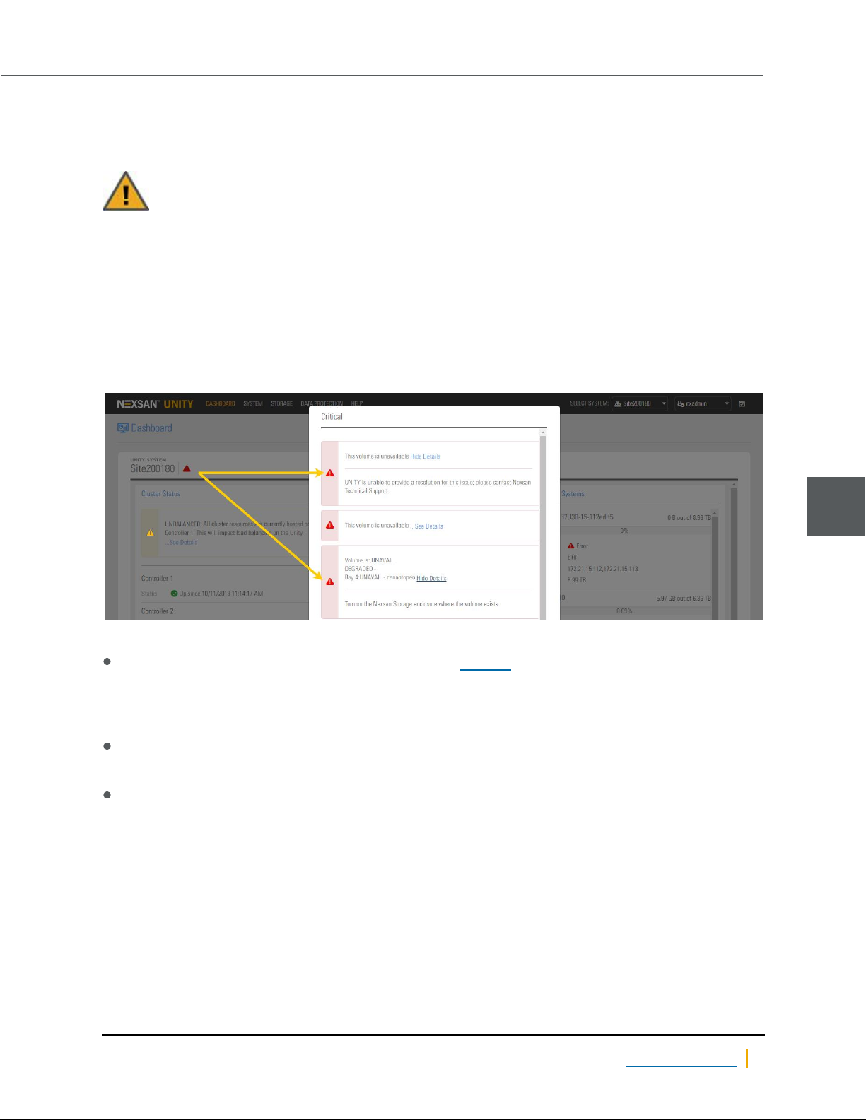
Firstly, when a disk fails, a warning is displayed on the Unity Storage System Dashboard panel.
Figure 1-2: Data disk failure error popup
Also, one of two other indicators appears:
If a spare disk is available, the Tasks in Progress dialog displays a “resilvering” process, which means that
the spare disk is being configured as a replacement for the failed disk.
Note It can take several hours to several days for the disk resilvering process to complete, depending on how
much data needs to be copied to the spare disk.
If there is no spare disk available, the Storage Pool node also displays a failure icon.
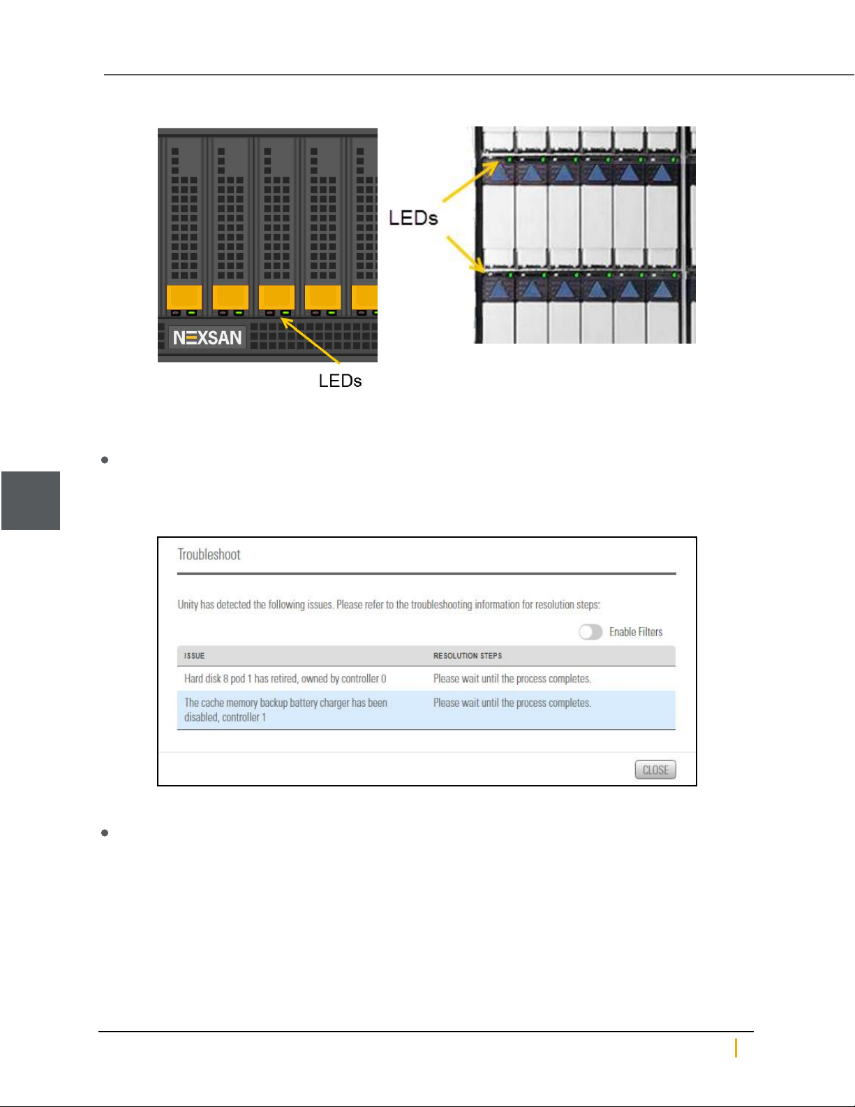
Secondly, the disk LEDs on the front of the Unity Storage System indicate which disk has failed.
A steady red LEDon a drive indicates failure.
1
Nexsan Unity www.nexsan.com 11
Page 12
1
Disk drives
Figure 1-3: Example drive LEDs:Unity 2200 (left) and US 460
► Troubleshooting
On the Unity navigation bar, click System >Troubleshoot to display the troubleshooting popup, which
contains more information about each Issue that the Unity System is currently experiencing, and
resolution steps.
Figure 1-4: Troubleshooting information
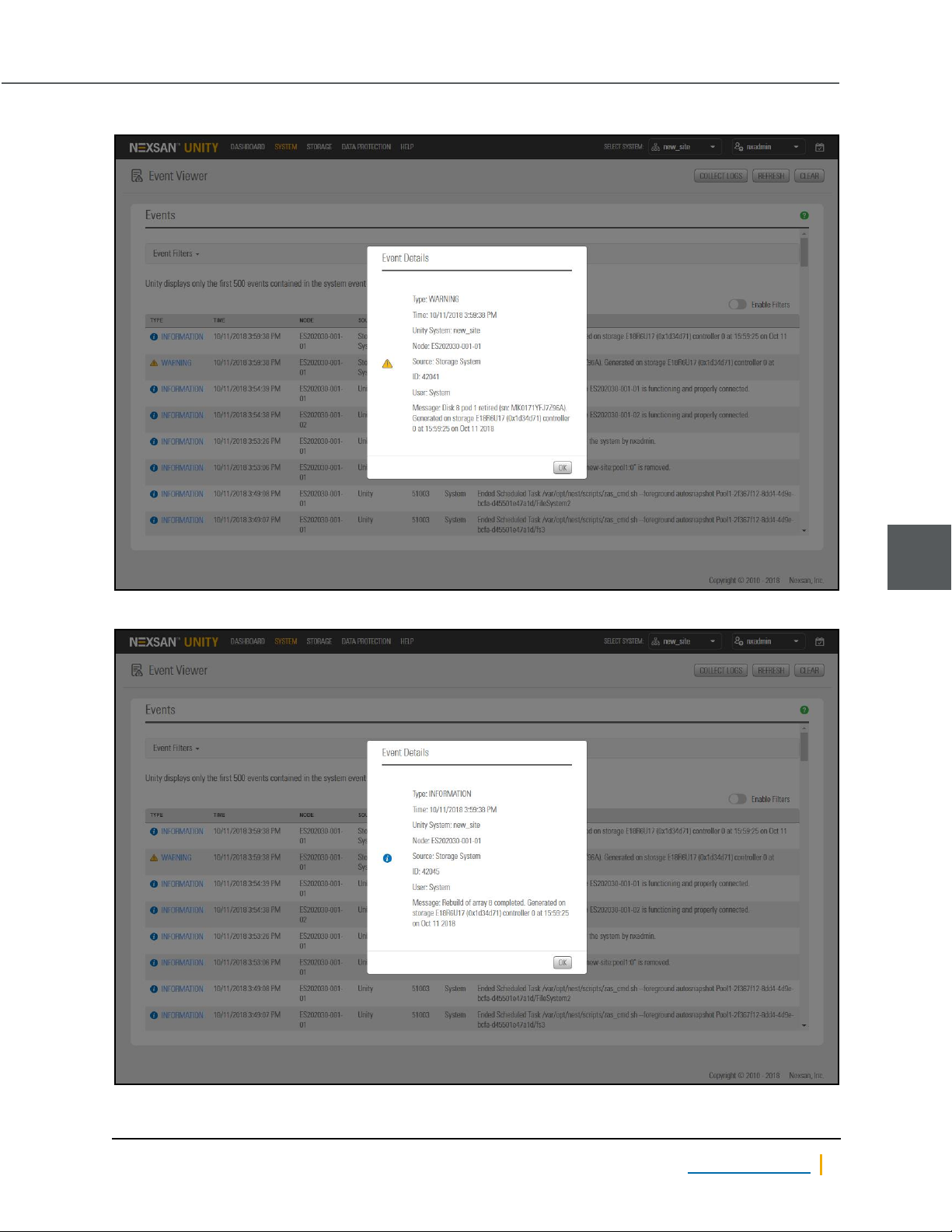
► Check Event Viewer
On the Unity navigation bar, click System >Event Viewer. The Event Viewer includes Critical,
Warning, Error, and optionally Information events. Click a link to an event to display a popup of the
information.
Nexsan Unity Hardware Maintenance Guide v. 5.1 Unity 12
Page 13
Chapter 1: Customer-Replaceable Units: Class 1
Figure 1-5: Event log entry for failed disk
Figure 1-6: Event log entry indicating that the disk (array) has been rebuilt
1
Nexsan Unity www.nexsan.com 13
Page 14
Disk drives
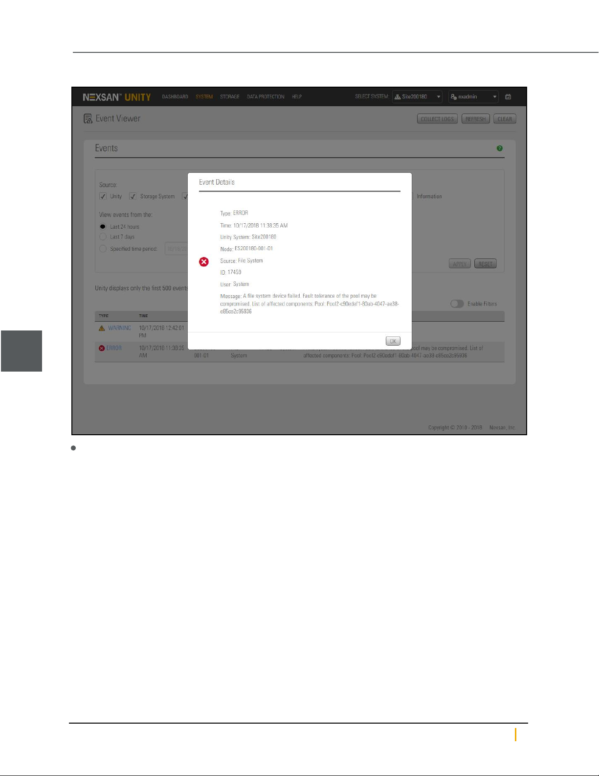
Figure 1-7: Event log entry for a degraded storage pool
1
In the command-line interface (CLI), run the drives command. The number of the drive bay where the failed
disk is installed will be missing from the list.
Example, with “Slot 5” missing, indicating the failed disk:
ES260768-176-01:A:/>drives
Enumerating drives...
Drives in NST5100 (Chassis ID 100000001, Slots: 16)
* Slot 1: ATA-INTEL-SSDSA2CW30 0362 (Serial: XXXXXXX, Size: 300 GB)
* Slot 2: SEAGATE-ST32000444SS 0006 (Serial: XXXXXXX, Size: 2.0 TB)
* Slot 3: SEAGATE-ST32000444SS 0006 (Serial: XXXXXXX, Size: 2.0 TB)
* Slot 4: SEAGATE-ST32000444SS 0006 (Serial: XXXXXXX, Size: 2.0 TB)
* Slot 6: SEAGATE-ST32000444SS 0006 (Serial: XXXXXXX, Size: 2.0 TB)
* Slot 7: SEAGATE-ST32000444SS 0006 (Serial: XXXXXXX, Size: 2.0 TB)
* Slot 8: SEAGATE-ST32000444SS 0006 (Serial: XXXXXXX, Size: 2.0 TB)
* Slot 9: SEAGATE-ST32000444SS 0006 (Serial: XXXXXXX, Size: 2.0 TB)
* Slot 10: SEAGATE-ST32000444SS 0006 (Serial: XXXXXXX, Size: 2.0 TB)
* Slot 11: SEAGATE-ST32000444SS 0006 (Serial: XXXXXXX, Size: 2.0 TB)
* Slot 12: SEAGATE-ST32000444SS 0006 (Serial: XXXXXXX, Size: 2.0 TB)
* Slot 13: SEAGATE-ST32000444SS 0006 (Serial: XXXXXXX, Size: 2.0 TB)
* Slot 14: SEAGATE-ST32000444SS 0006 (Serial: XXXXXXX, Size: 2.0 TB)
* Slot 15: SEAGATE-ST32000444SS 0006 (Serial: XXXXXXX, Size: 2.0 TB)
* Slot 16: SEAGATE-ST32000444SS 0006 (Serial: XXXXXXX, Size: 2.0 TB)
Nexsan Unity Hardware Maintenance Guide v. 5.1 Unity 14
Page 15
Chapter 1: Customer-Replaceable Units: Class 1
When you have all required information, including the specific drive bay that the failed disk occupies, proceed
to Replacing data disks on page18.
1
Nexsan Unity www.nexsan.com 15
Page 16
1
Disk drives
FASTier disk failures
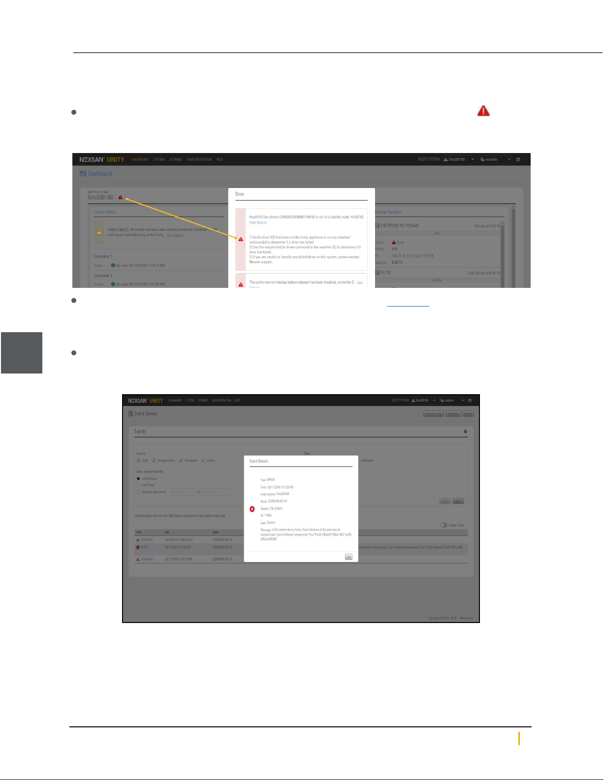
When a FASTier disk fails,
a warning is displayed on the Unity Storage System Dashboard panel. Click the Warning icon ,
displayed beside the Unity System name for details, as shown here:
Figure 1-8: FASTier disk failure error popup
the disk LEDs on the front of the unit indicate which disk has failed. See Figure 1-3
► For more information about the failed FASTier disk:
Do one or more of the following:
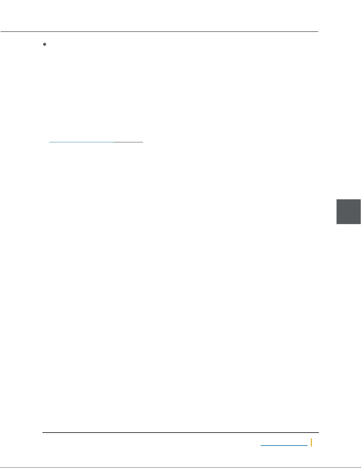
Open the Event Viewer to display system events. Click an event to open a detail dialog with additional
information.
Figure 1-9: Event log entry for failed FASTier disk
Note Because there is no other Unity notification of a failed FASTier drive, it is highly recommended that you
configure Unity to send an e-mail whenever a CRITICAL event occurs so that you are notified in the event of a
FASTier failure. See "Event logging and notification" in the Nexsan Unity Software User Guide.
Nexsan Unity Hardware Maintenance Guide v. 5.1 Unity 16
Page 17
Chapter 1: Customer-Replaceable Units: Class 1
In the command-line interface (CLI), run the drives command to display information about the disk failure.
Example, with “Slot 1” missing, indicating the failed FASTier™ disk:
ES260768-176-01:A:/>drives
Enumerating drives...
Drives in NST5100 (Chassis ID 100000001, Slots: 16)
* Slot 2: SEAGATE-ST32000444SS 0006 (Serial: XXXXXXX, Size: 2.0 TB)
* Slot 3: SEAGATE-ST32000444SS 0006 (Serial: XXXXXXX, Size: 2.0 TB)
* Slot 4: SEAGATE-ST32000444SS 0006 (Serial: XXXXXXX, Size: 2.0 TB)
.
.
.
When you have all required information, including the specific drive bay that the failed disk occupies, proceed
to Replacing FASTier drives on page22.
1
Nexsan Unity www.nexsan.com 17
Page 18
1
Disk drives
Replacing data disks
It is always recommended that you replace failed disk drives immediately to ensure that the system has an
adequate number of spare drives.
► To replace a failed data drive:
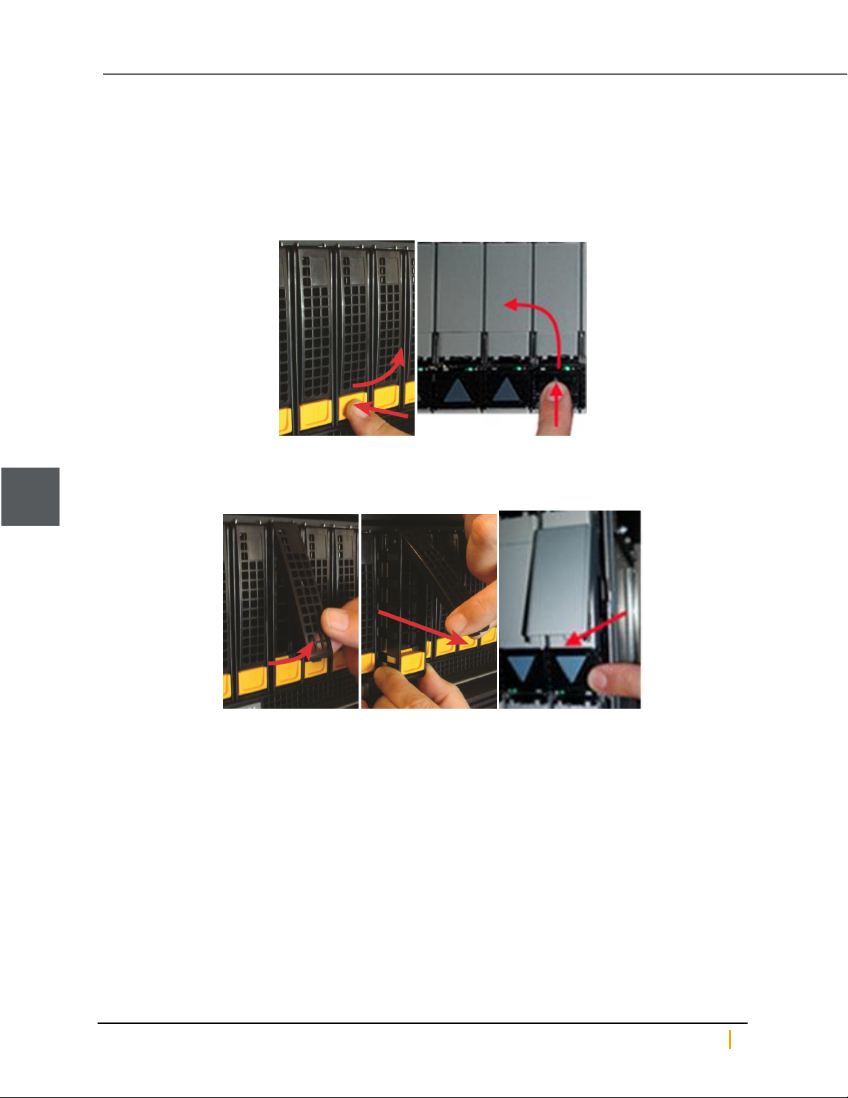
1. Press the release switch down to unlatch the drive extraction lever. The lever pops out.
Figure 1-10: Unlatching the extraction lever
2. Using the drive extraction lever, pull the disk drive out approximately 1/2 to 1 inch, then grasp the drive
carrier body and remove the drive the rest of the way.
Figure 1-11: Removing the disk drive
Nexsan Unity Hardware Maintenance Guide v. 5.1 Unity 18
Page 19
Chapter 1: Customer-Replaceable Units: Class 1
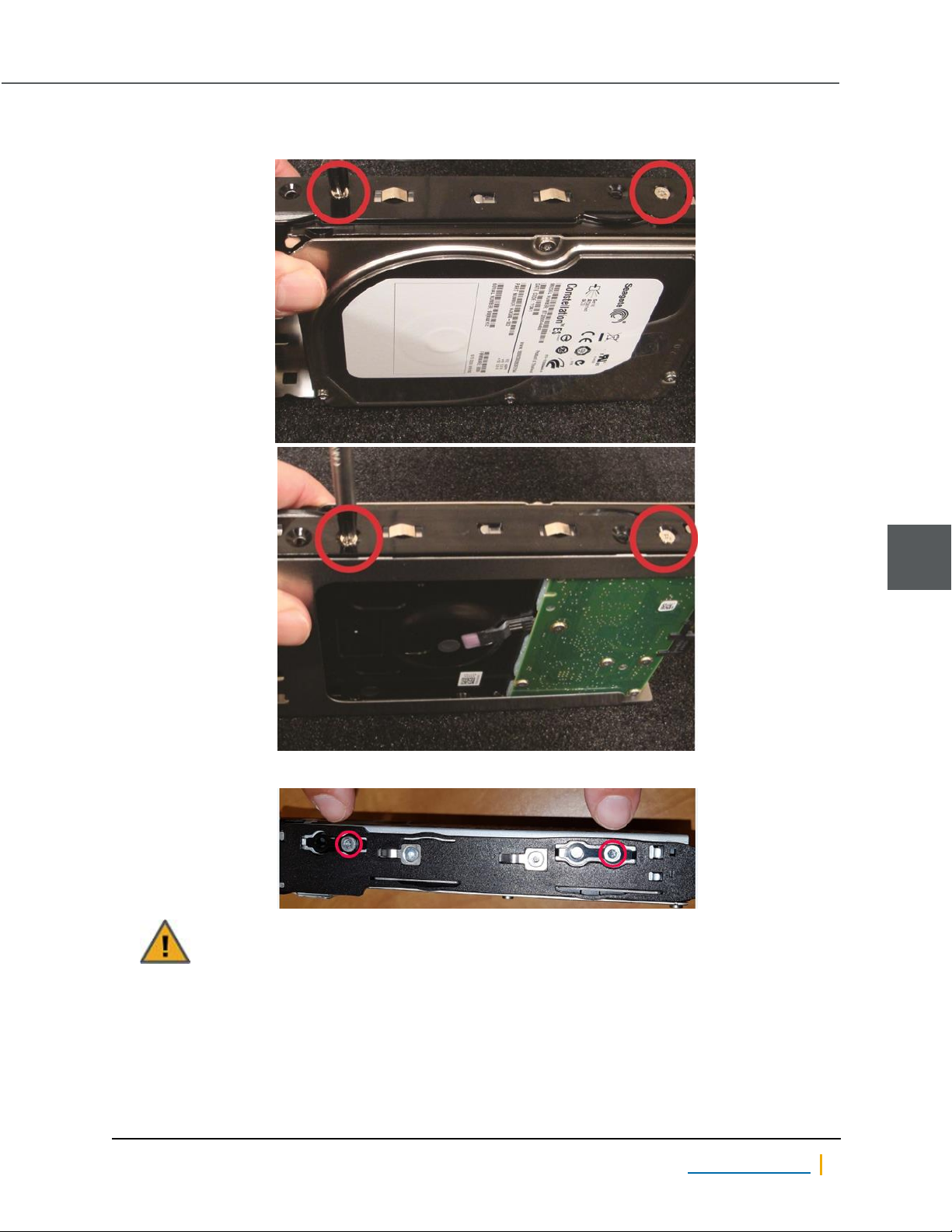
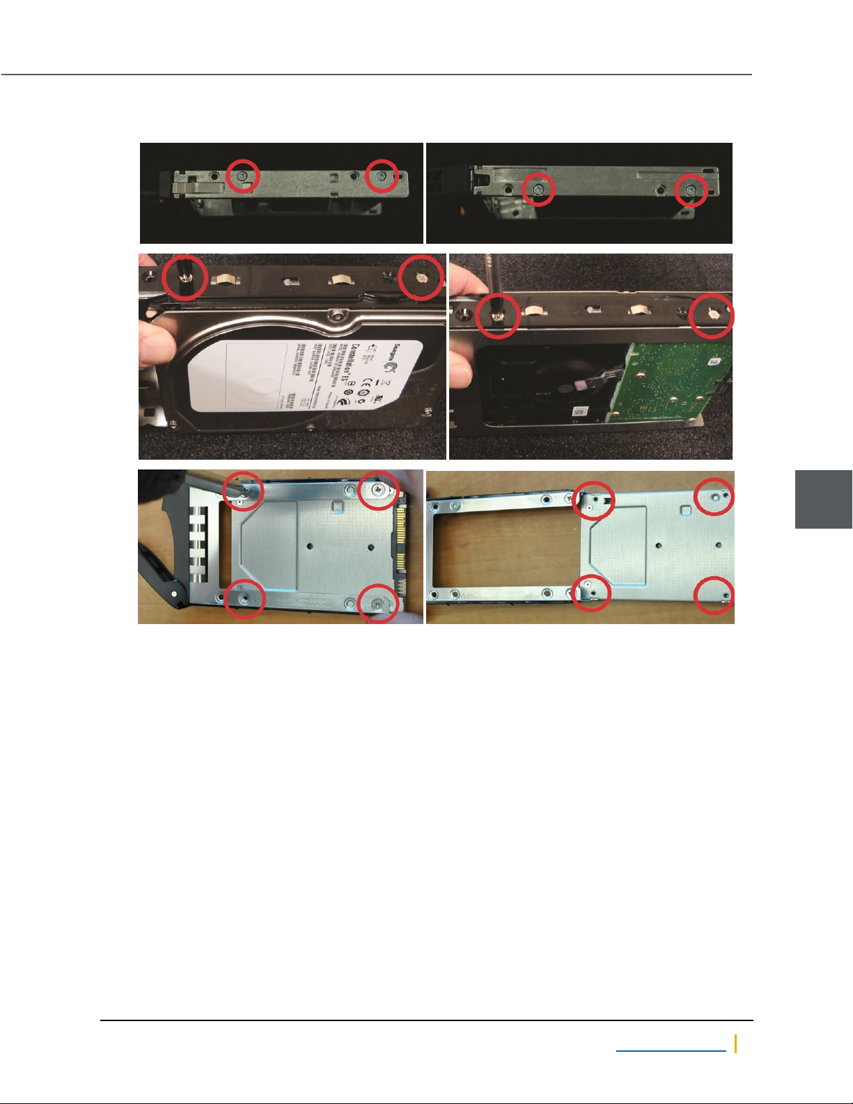
3. Remove the drive carrier from the failed disk and attach it to the new disk.
Figure 1-12: Drive carrier screw locations
Figure 1-13: US 460
CAUTION: ALWAYS put replacement disk drives into the slot from which the failed disk drives
were removed. Do NOT move disk drives between slots.
1
Nexsan Unity www.nexsan.com 19
Page 20
Disk drives
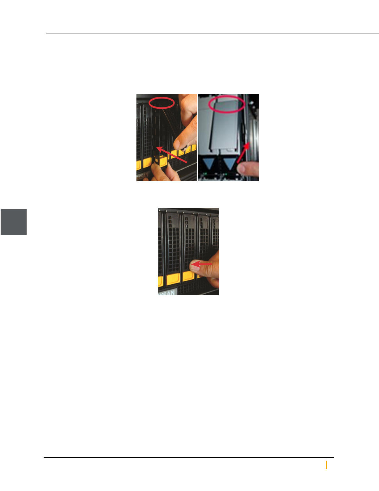
4. Install the new disk drive:
a. Line up the carrier guides with the guides on the front of the Nexsan Unity chassis and slide the disk
drive into the slot.
b. Hook the top of the extraction handle onto the lip of the chassis.
Figure 1-14: Installing the new disk drive
c. Press the extraction handle until it clicks into place.
Figure 1-15: Latching the new disk into place
1
The appropriate disk LED lights up green to let you know that the disk is operating properly.
If the storage pool had an available spare, the new disk is configured as a spare. The failure icons in Unity are
cleared and the Event Viewer shows that the disk has been restored.
Nexsan Unity Hardware Maintenance Guide v. 5.1 Unity 20
Page 21
Chapter 1: Customer-Replaceable Units: Class 1
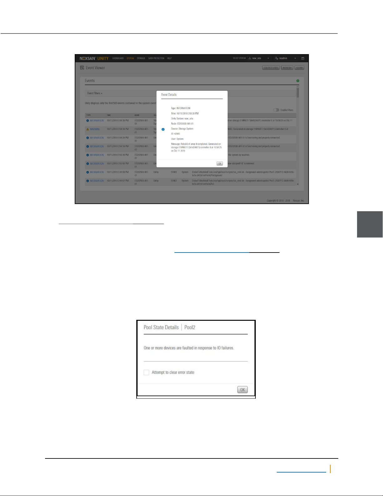
Figure 1-16: Event indicating that a disk (array) has been rebuilt
If the storage pool did not have an available spare, the new disk is “resilvered” and built into the storage pool
(see Identifying failed disk drives on page11). Resilvering can take several hours to several days.
When all failure conditions are addressed (the disk is replaced, resilvering is complete, and the storage pool is
operating normally), the Event Viewer indicates this.
Note In some cases, the storage pool error (see Identifying failed disk drives on page11) is not automatically
cleared when the resilvering process is complete. In such cases, perform the following procedure:
► To clear the storage pool error after disk resilvering is complete:
1. On the Unity navigation bar, select Storage > Storage Pools.
2. Click the link to the pool that displays the error.
3. Check the Attempt to clear error state check box and click OK.
Figure 1-17: Attempt to clear error state check box
1
The storage pool error is cleared.
Nexsan Unity www.nexsan.com 21
Page 22
Disk drives
Replacing FASTier drives
► To replace a failed FASTier drive:
1. First you must remove the failed FASTier drive from the storage pool to which it is assigned:
a. On the Unity navigation bar, select Storage > Storage Pools.
b. Click the link to the pool that the FASTier disk is assigned to.
c. Select Summary >FASTier Cache.
Unity displays the number of available FASTier devices on the system. This number is the number
of installed FASTier disks, minus one.
d. Make the appropriate FASTier cache assignments, either READor WRITE, depending on your
system and disk options. See "FASTier caching by storage system" in the Unity Software User
Guide.
e. Click the Apply button.
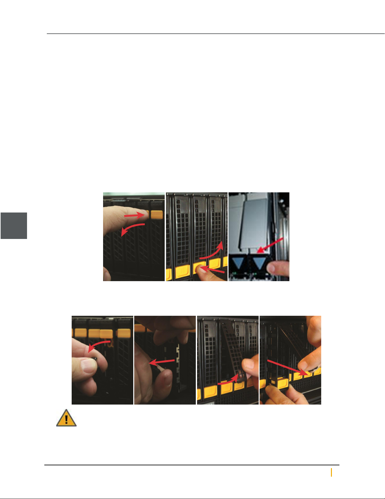
2. Press the latch switch down to unlatch the drive extraction lever. The lever pops out.
Figure 1-18: Unlatching the extraction lever
1
3. Using the drive extraction lever, pull the disk drive out approximately 1/2 to 1 inch, then grasp the drive
carrier body and remove the drive the rest of the way.
Figure 1-19: Removing the FASTier drive
CAUTION: ALWAYS put replacement disk drives into the slot from which the failed disk drives
were removed. Do NOT move disk drives between slots.
Nexsan Unity Hardware Maintenance Guide v. 5.1 Unity 22
Page 23
Chapter 1: Customer-Replaceable Units: Class 1
4. Remove the drive carrier from the failed disk and attach it to the new disk.
Figure 1-20: Example drive carrier screw locations
Note US 460 Expansions do not use drive carriers for each drive.
1
Nexsan Unity www.nexsan.com 23
Page 24
Disk drives
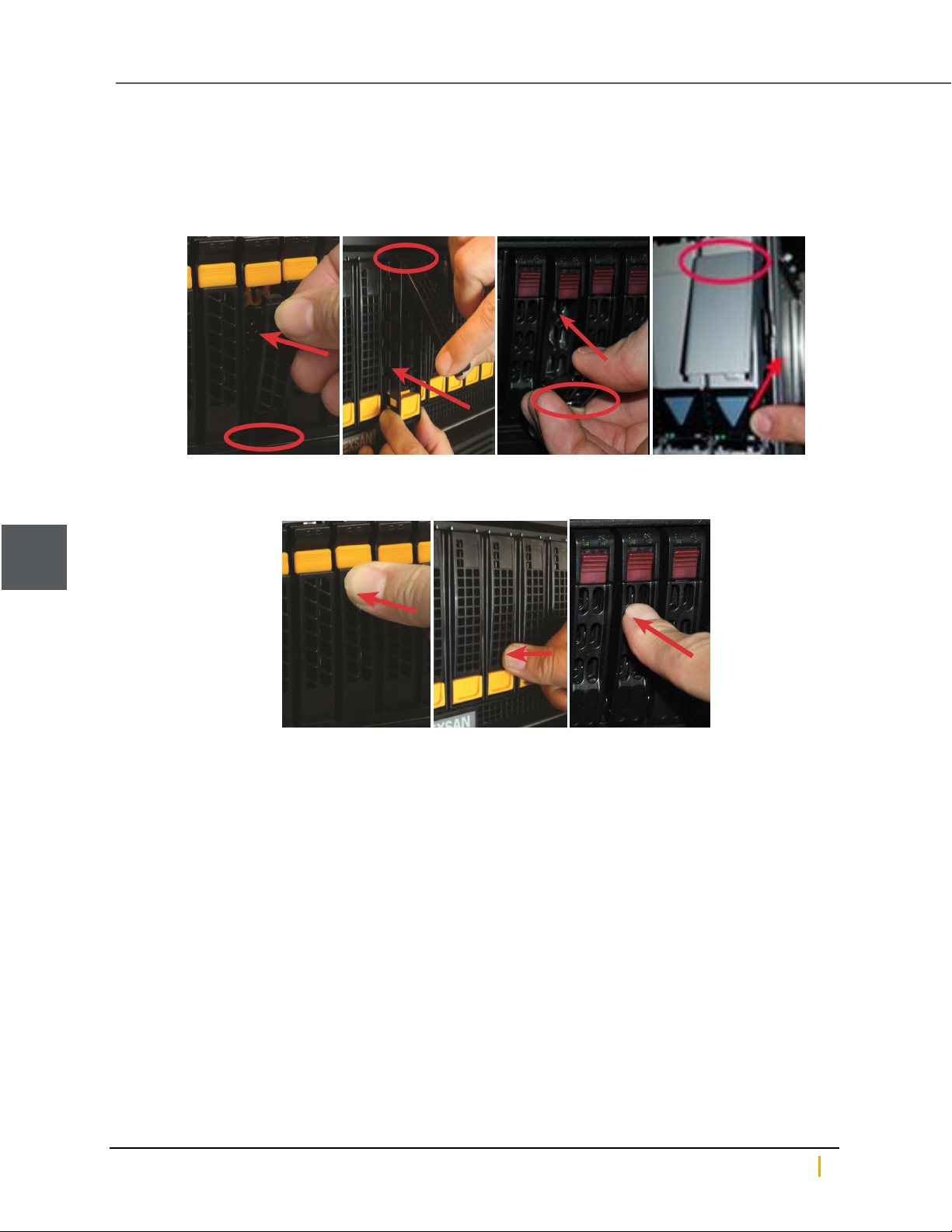
5. Install the new disk drive:
a. Line up the carrier guides with the guides on the front of Unity chassis and slide the disk drive into
the slot.
b. Hook the bottom of the extraction handle beneath the lip of the chassis.
Figure 1-21: Installing the new FASTier drive
c. Press the extraction handle until it clicks into place.
Figure 1-22: Latching the FASTier disk into place
1
An event is recorded in the event log and can be accessed in the Event Viewer.
6. Assign the new FASTier drive to the storage pool that the old FASTier drive was assigned to.
a. On the Unity navigation bar, select Storage > Storage Pools.
b. Click the link to the pool that the FASTier disk is assigned to.
c. Select Summary >FASTier Cache.
Unity displays the number of available FASTier devices on the system. This number is the number
of installed FASTier disks, minus one.
d. Make the appropriate FASTier cache assignments, either READor WRITE, depending on your
system and disk options. See "FASTier caching by storage system" in the Unity Software User
Guide.
e. Click the Apply button.
Nexsan Unity Hardware Maintenance Guide v. 5.1 Unity 24
Page 25
Chapter 1: Customer-Replaceable Units: Class 1
Power supply units (PSUs)
Unity Storage Systems include redundant power supply units (PSUs). In case one fails, the unit can continue
to operate for a brief period using only the power from the other PSU.
Note The cooling fans in each PSU operate on separate circuits from the power supply itself. If one PSU fails,
its fans continue to run on power supplied by the other PSU.
CAUTION: When a failed PSU is removed, ALWAYS replace it as soon as possible. Two functional
PSUs are necessary to maintain proper operation and cooling for the unit.
Identifying failed power supply units (PSUs)
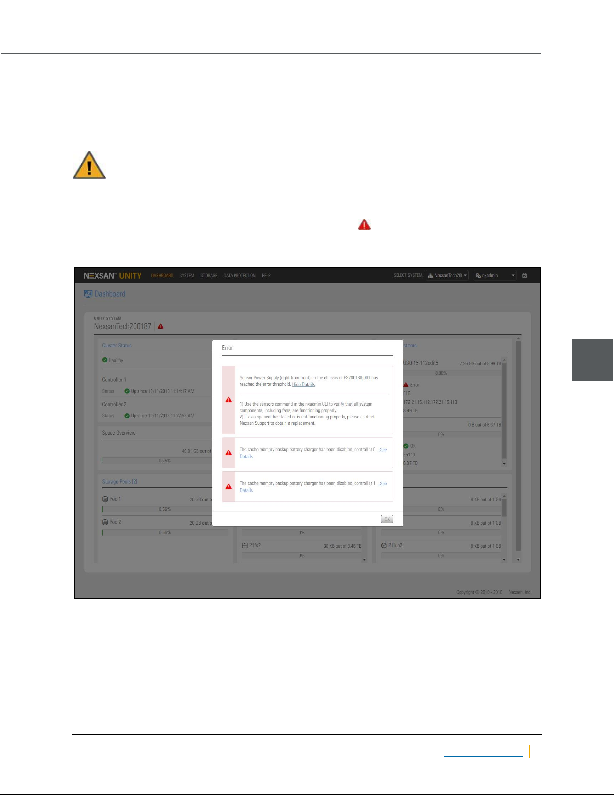
A failed power supply unit (PSU) is indicated by a critical error icon at the top of the Unity Dashboard.
Click the icon for details.
Figure 1-23: Power supply failure error from the Dashboard
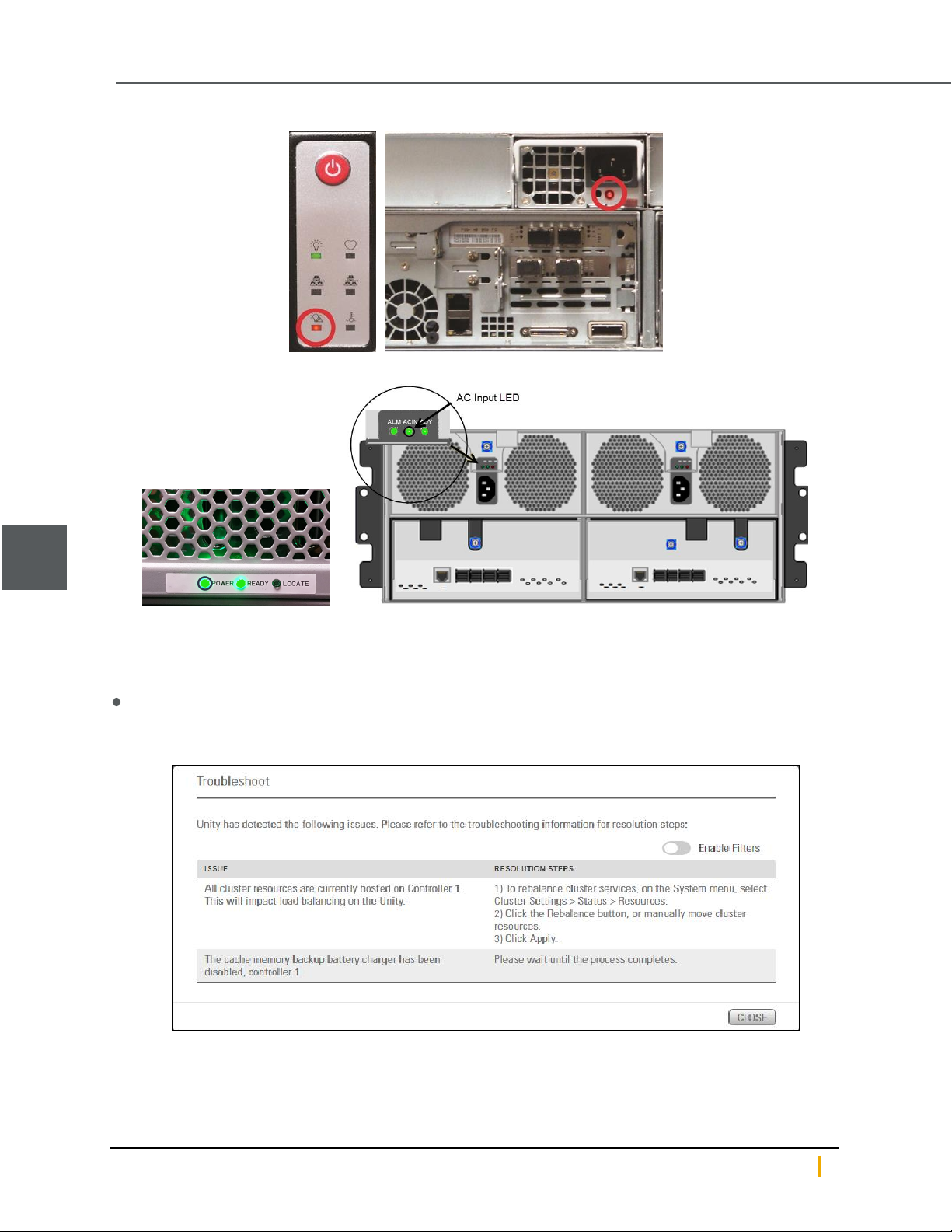
On most Unity systems, the front-panel power failure LED corresponding to the failed PSU is illuminated, and
the status LED on the back of the PSU is either red or off.
1
Nexsan Unity www.nexsan.com 25
Page 26
Power supply units (PSUs)
Standard power failure LED (left) and PSU status LED (right)
US460 front power LED(left) and rear ACInput LED
1
Note If the front chassis power failure LED is flashing rather than steadily lit up, this indicates a fan failure
rather than a PSU failure. See Fans on page43.
► For more information about the failed PSU, do one or more of the following:
On the Unity navigation bar, click System >Troubleshoot to display the troubleshooting popup, which
contains more information about the PSU failure.
Figure 1-24: Troubleshooting popup
Nexsan Unity Hardware Maintenance Guide v. 5.1 Unity 26
Page 27
Chapter 1: Customer-Replaceable Units: Class 1
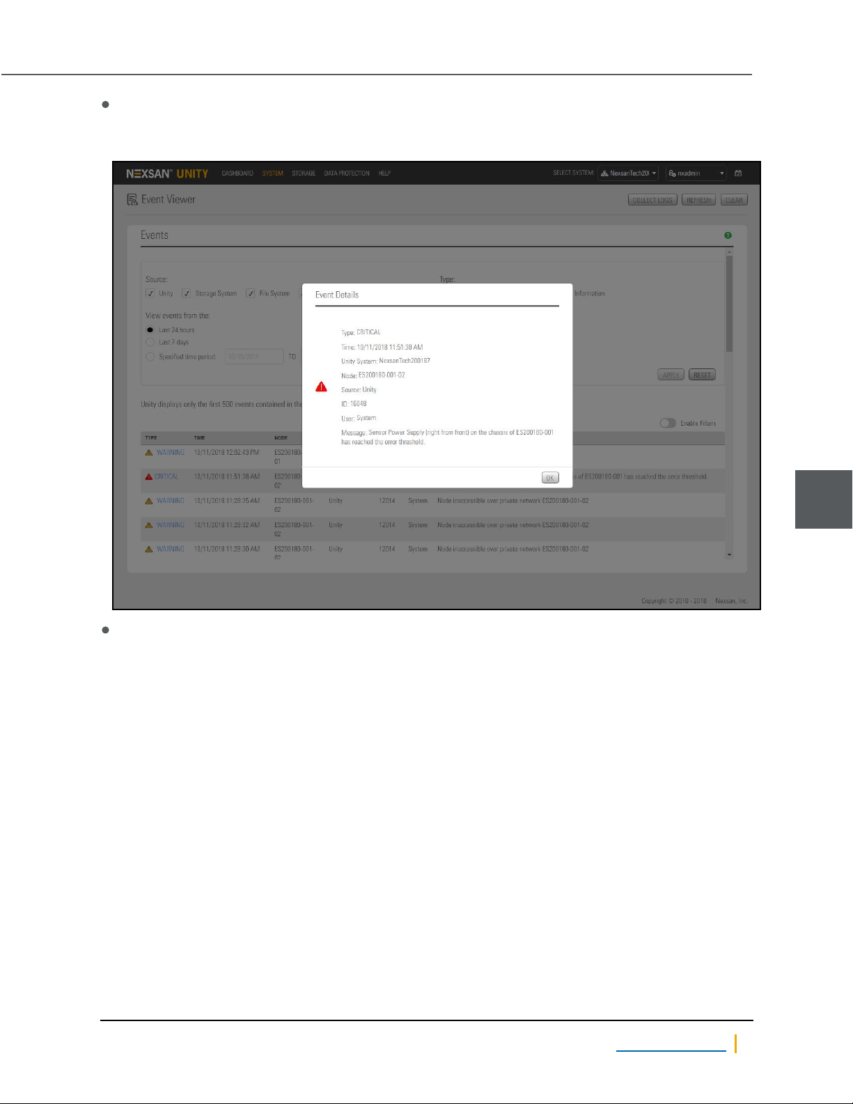
Check Event Viewer: On the Unity Dashboard , click Events to open the Event Viewer, with links to
Critical, Warning, Error, and Information events.
Figure 1-25: Event log entry for failed PSU
In the command-line interface (CLI), run the sensors command to display information about the failure.
Example, with Power Supply (right from front) showing a status of “down”
Sensors for E5110 chassis:
ERROR * Power Supply(right from front) (discrete): down
* Power Supply(left from front) (discrete): normal
* Temperature (right from front) (temperature): normal [30 C]
* Temperature (left from front) (temperature): normal [35 C]
* 5V supply voltage (voltage): unknown [0.00V]
* 12V supply voltage (voltage): unknown [0.00 V]
* 5V supply current (misc): unknown
* 12V supply current (misc): unknown
.
.
.
1
When you have all required information, including the specific power supply unit that has failed, continue with
the appropriate replacement procedure.
Nexsan Unity www.nexsan.com 27
Page 28
Power supply units (PSUs)
Replacing a standard PSU
► To replace a standard PSU:
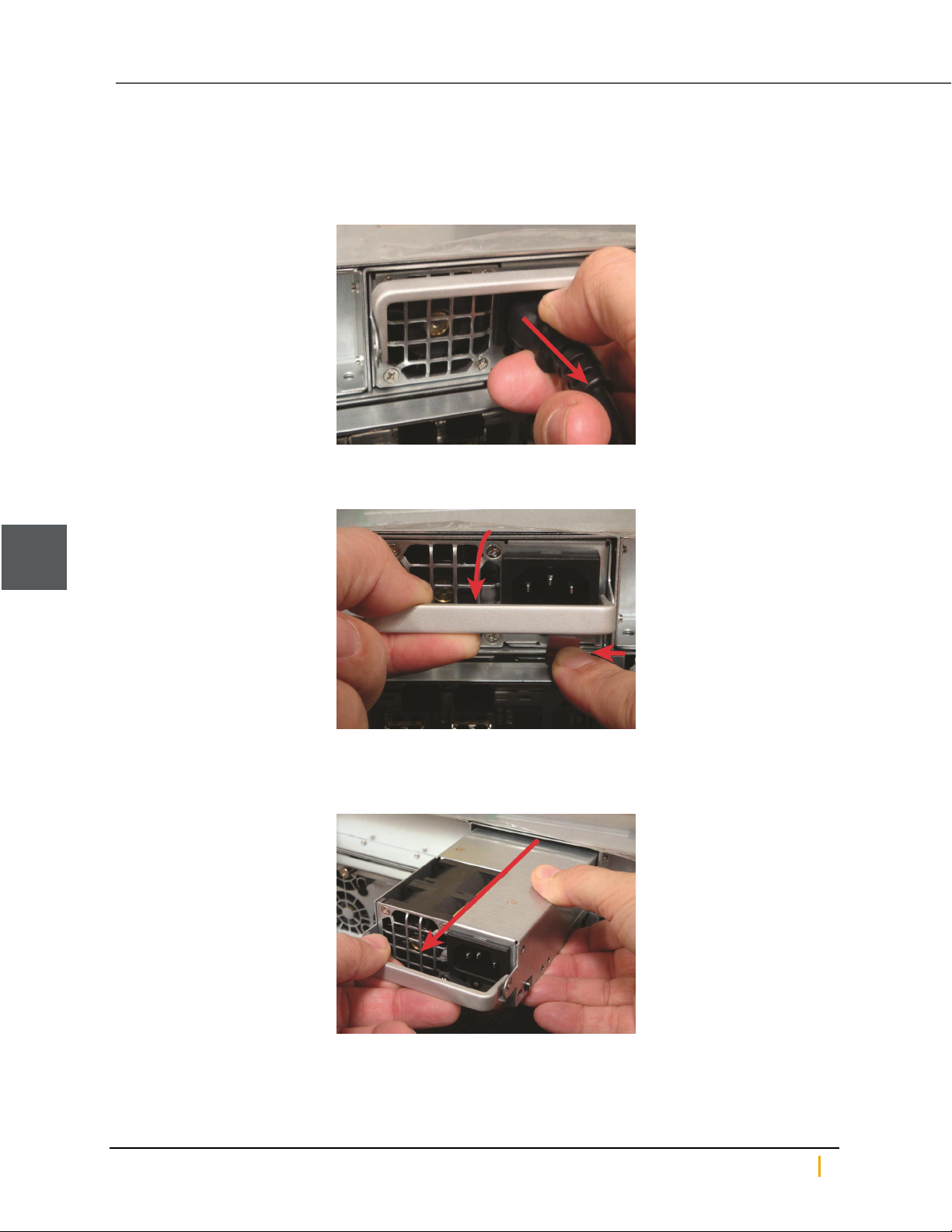
1. Remove the power cord from the failed PSU.
Figure 1-26: Removing the power cord
2. Fold down the extraction handle and press the latch tab inward, to the left.
Figure 1-27: Unlatching the PSU
1
3. Gently pull the extraction handle and remove the PSU from the slot, supporting its weight with your other
hand.
Figure 1-28: Removing the PSU
4. Orient the replacement PSU so that the latch tab is on the right.
Nexsan Unity Hardware Maintenance Guide v. 5.1 Unity 28
Page 29
Chapter 1: Customer-Replaceable Units: Class 1
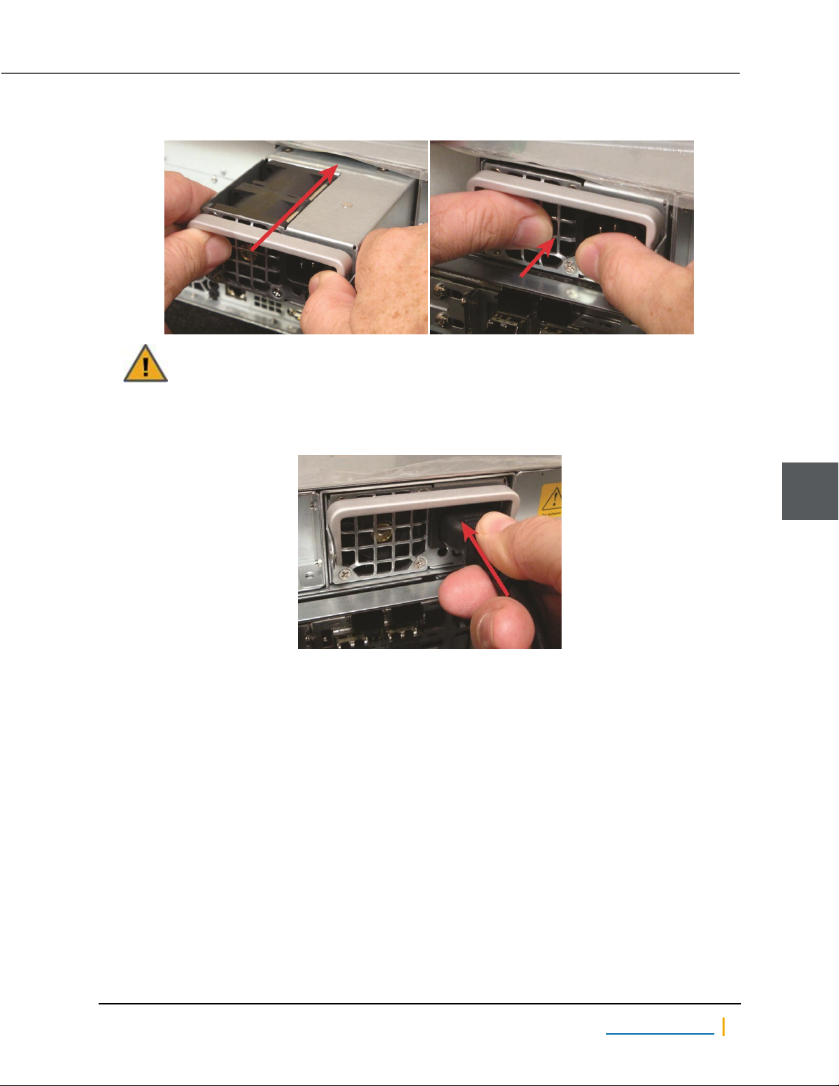
5. Guide the new PSU into the slot and slide it in until it is fully seated.
Figure 1-29: Installing the new PSU
CAUTION: Make certain that the power supply unit is FULLY SEATED before applying power.
6. Place the power cord in the power socket on the PSU.
Figure 1-30: Applying power to the PSU
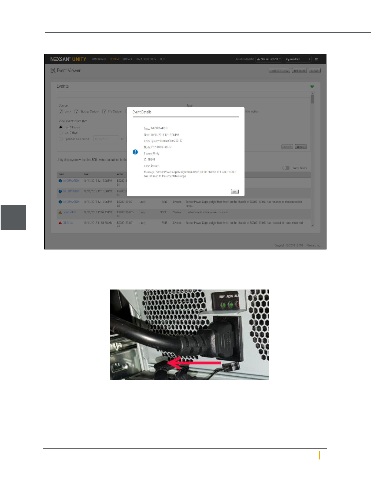
The PSU Status LED lights up green to let you know that the new PSU is working properly, and the power fail
LED on the front of the unit turns off. Also, an event is recorded in the event log and can be accessed in the
Event Viewer. To open Event Viewer, on the Unity Dashboard, click Events.
1
Nexsan Unity www.nexsan.com 29
Page 30
Power supply units (PSUs)
Figure 1-31: Event indicating that the PSU has returned to an acceptable range
1
Replacing a US 460 PSU
► To replace a US 460 PSU:
1. Remove the power cord from the failed PSU.
Nexsan Unity Hardware Maintenance Guide v. 5.1 Unity 30
Page 31
Chapter 1: Customer-Replaceable Units: Class 1
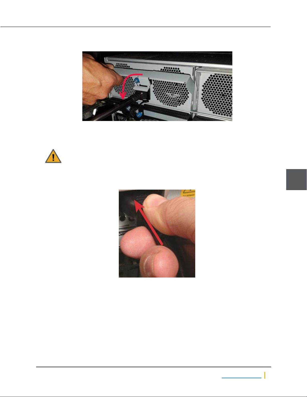
2. Fold down the extraction handle.
Figure 1-32: Unlatching the PSU
3. Gently pull the extraction handle and remove the PSU from the slot, supporting its weight with your other
hand.
4. Guide the new PSU into the slot and slide it in until it is fully seated.
CAUTION: Make certain that the power supply unit is FULLY SEATED before applying power
by plugging in the unit.
5. Place the power cord in the power socket on the PSU.
Figure 1-33: Applying power to the PSU
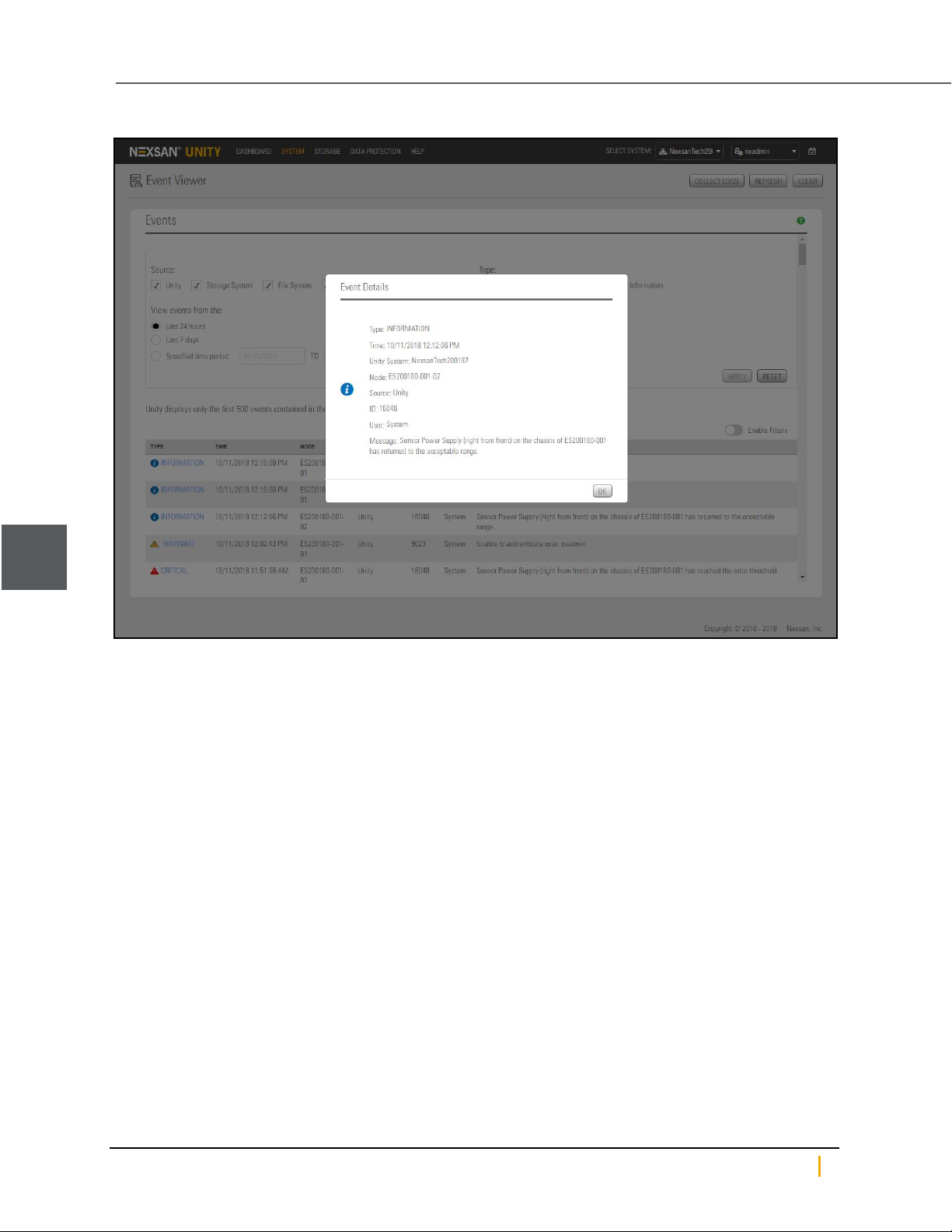
The PSU Status LED lights up green to let you know that the new PSU is working properly, and the power
LED on the front of the unit turns green. Also, an event is recorded in the event log and can be accessed in the
Event Viewer. On the Unity Dashboard , click Events to open the Event Viewer.
1
Nexsan Unity www.nexsan.com 31
Page 32
Power supply units (PSUs)
Figure 1-34: Event indicating that the PSU has returned to an acceptable range
1
Nexsan Unity Hardware Maintenance Guide v. 5.1 Unity 32
Page 33
Chapter 1: Customer-Replaceable Units: Class 1
SFPs
SFPs (small form pluggable) ports on the Fibre Channel can be individually replaced in case of failure. This
procedure only applies to Unity Storage Systems equipped with Fibre Channel cards.
CAUTION: Only perform this procedure if the system is wired for redundancy. This is to avoid loss
of network connectivity or access to external storage.
► To replace SFPs on a Fibre Channel:
1. Remove the cable from the SFP connector.
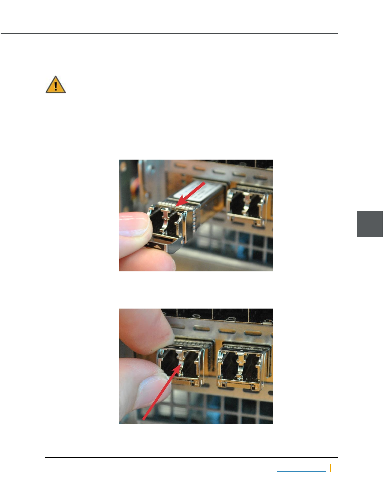
2. Fold down the small extraction handle on the SFP, then gently pull the SFP out of the slot.
Figure 1-35: Removing the SFP
3. Orient the new SFP so that the extraction handle points up.
4. Gently slide the new SFP into the slot until it is fully seated.
Figure 1-36: Replacing the SFP
1
5. Attach the cable you removed in Step 1 to the new SFP connector.
Nexsan Unity www.nexsan.com 33
Page 34

SFPs
Nexsan Unity Hardware Maintenance Guide v. 5.1 Unity 34
Page 35

Chapter 2
Chapter 2:Customer Replaceable Units: Class 2
Class 2 CRUs - The following components of Nexsan Unity are replaceable by the customer, typically
without assistance from Technical Support, but do have some associated risk of causing a complete or partial
system failure if the documented replacement procedure is not followed correctly. If you are unsure about a
specific step or process, please contact Nexsan Support for assistance.
This chapter contains the following sections:
Unity Storage Expansion controllers 36
System sub-components 41
Fans 43
2
Nexsan Unity www.nexsan.com 35
Page 36
Unity Storage Expansion controllers
Unity Storage Expansion controllers
When one Unity Storage Expansion controller fails, its resources (Pool Resource Group and storage pools)
are migrated to the remaining Unity Storage Expansion controller automatically.
Identifying a failed controller
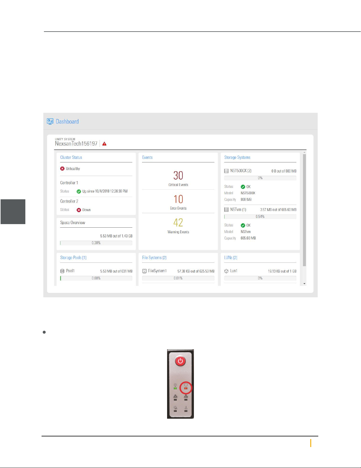
A failed controller in a storage system is indicated in Unity by error in the Cluster Status section of the
Dashboard panel.
Figure 2-1: Controller failure icons
2
Check the front panel LEDs for controller errors
► For all Unity Storage Systems
The heartbeat LED turns red.
Figure 2-2: Controller fault LED indicators
Nexsan Unity Hardware Maintenance Guide v. 5.1 Unity 36
Page 37
Chapter 2: Customer Replaceable Units: Class 2
Identify the controller numbers using the CLI
You can identify the controller numbers using the Unity nxcmd command-line interface.
► To display controller number:
Enter the nics command in the nxcmd CLI.
Description This command displays the physical locations of the network ports on the current
Controller node.
Controller Run this command on the controller where the network ports you wish to view information
for are located.
Syntax
Options None
Example
For details, consult the Nexsan Unity nxcmd Command Line Interface Reference Guide, available from the
Nexsan.com Unity support page.
nics
nics
System Chassis : Unity 2200
System Node # : 2
igb0 : 1000 RJ45 - 1G Copper Network Port
onboard, first port from the left
igb1 : 1000 RJ45 - 1G Copper Network Port
onboard, second port from the left
igb2 : 1000 RJ45 - 1G Copper Network Port
onboard, third port from the left
igb3 : 1000 RJ45 - 1G Copper Network Port
onboard, fourth port from the left
► For more information about the failed controller:
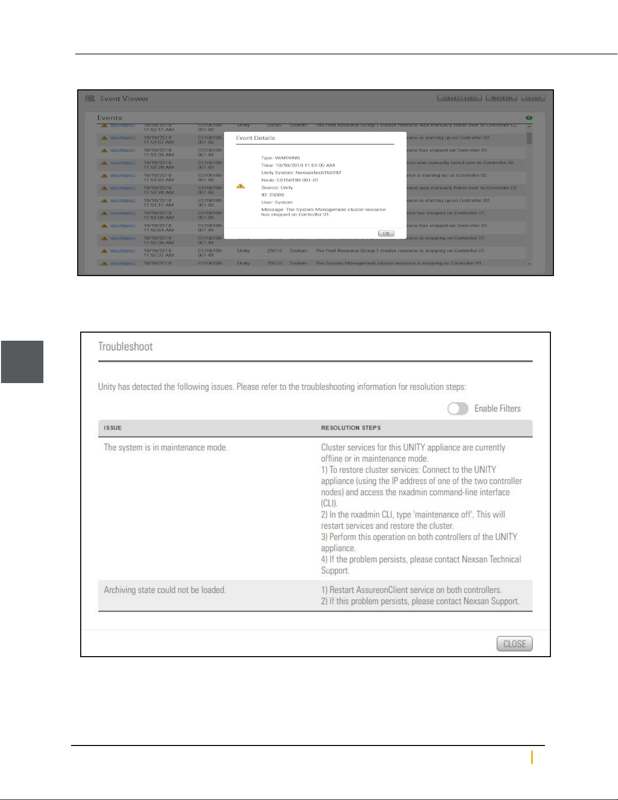
1. Check Event Viewer: On the Unity Dashboard , click Events to open the Event Viewer, which displays
Critical, Warning, and Error events. Click Error events to list Controller events.
2
Nexsan Unity www.nexsan.com 37
Page 38
Unity Storage Expansion controllers
Figure 2-3: Event log entry for failed controller
2. On the Unity navigation bar, click System >Troubleshoot to display the troubleshooting window,
which contains more information about the controller failure.
Figure 2-4: The troubleshoot popup
2
When you have all required information, including the specific controller that has failed, continue with the
appropriate replacement procedure.
Nexsan Unity Hardware Maintenance Guide v. 5.1 Unity 38
Page 39
Chapter 2: Customer Replaceable Units: Class 2
Replacing a Unity Storage Expansion controller
► To replace a failed Unity Storage Expansion controller:
1. Remove the SAS cables from the failed controller, being sure to label each SAS cable with the number of
the SAS port to which it was attached.
2. For standard controllers, remove the retaining bolt on the controller that needs to be replaced. See
Replacing a Unity Storage System controller on page54.
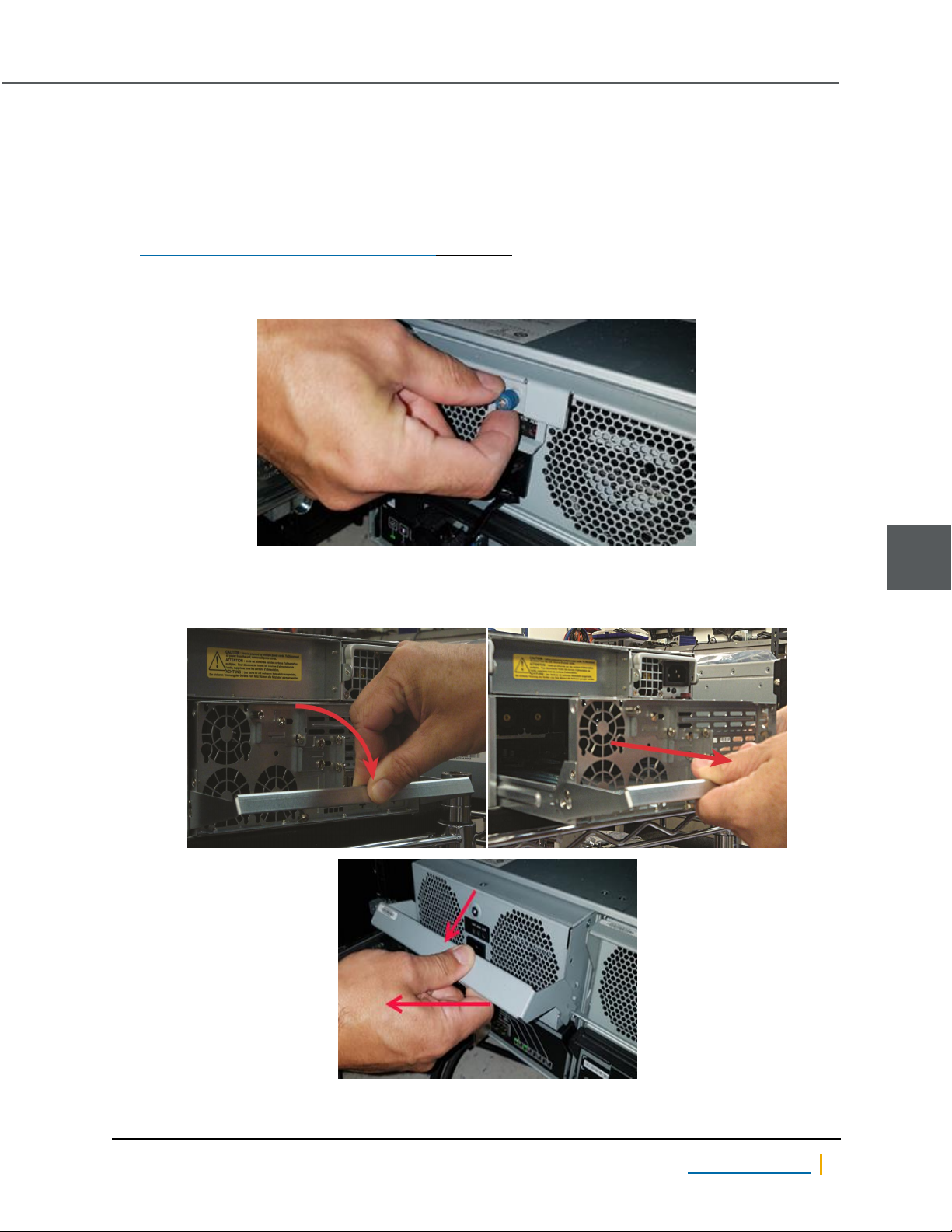
3. For the US 460 Expansion, remove the controller retaining bolt.
Figure 2-5: US 460 Expansion controller retaining bolt
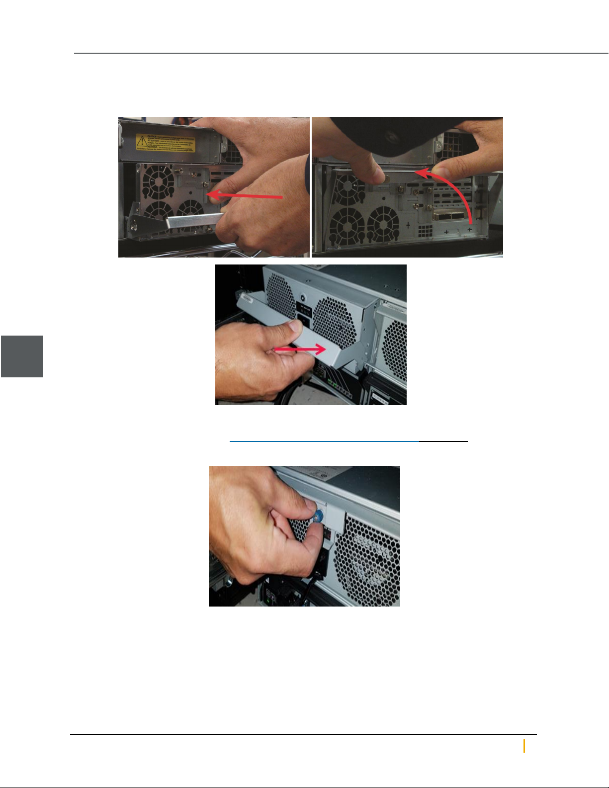
4. Pull down the extraction handle to disengage the controller from the unit, then gently pull the controller out
of the chassis, supporting its weight with the other hand.
Figure 2-6: Removing the Unity Storage Expansion controller
2
Nexsan Unity www.nexsan.com 39
Page 40
Unity Storage Expansion controllers
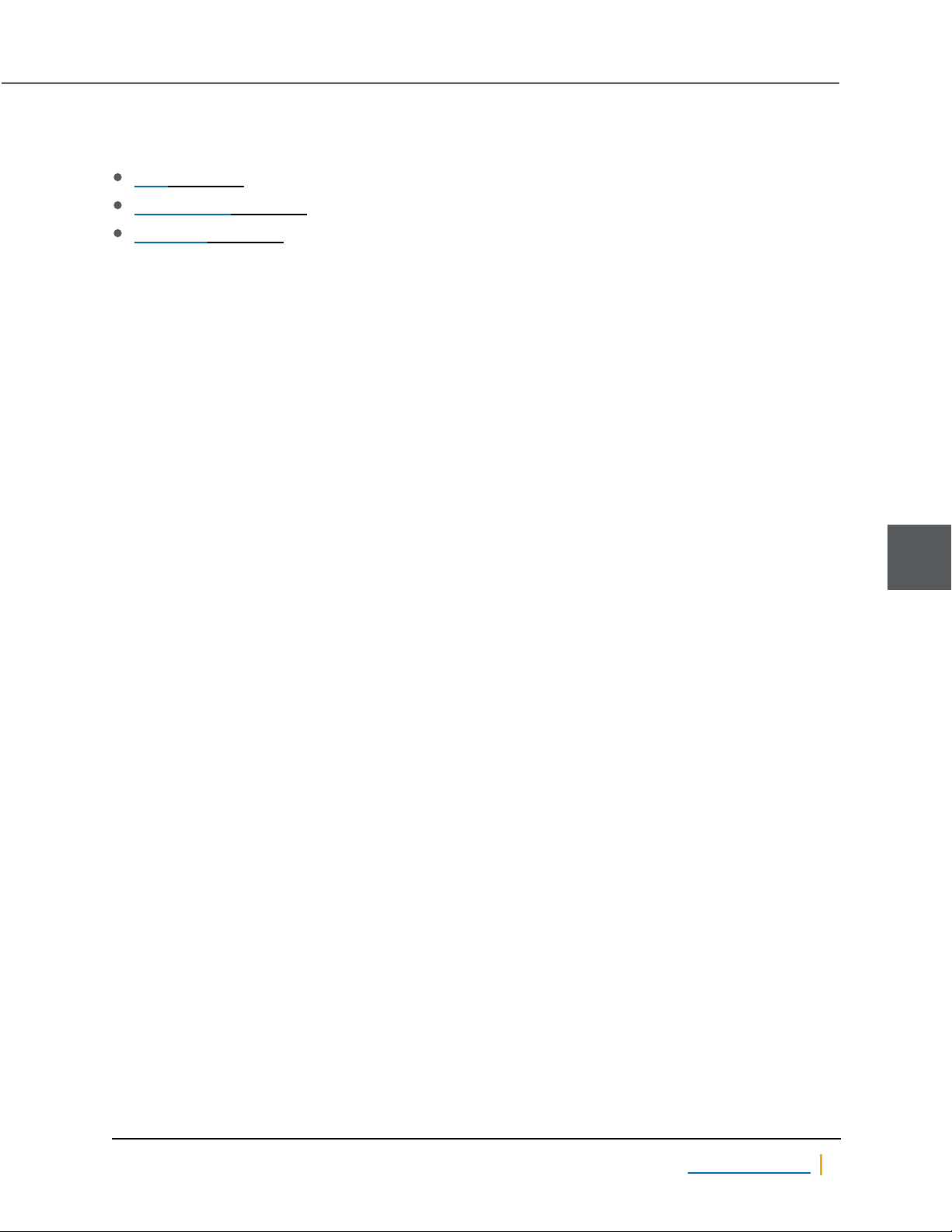
5. Guide the new controller into the slot and slide it in until some resistance is met, then push the extraction
handle up to seat the controller.
Figure 2-7: Inserting the new Unity Storage Expansion controller
2
6. Re-secure the controller retaining bolt.
a. For standard controllers, see Replacing a Unity Storage System controller on page54.
b. For the US 460 Expansion, fasten the controller retaining bolt.
7. Replace the SAS cables on the new controller, being sure to put all cables back into the proper ports. See
Step 1.
8. Open Unity and verify that the new controller is being recognized by the system. See Navigating Unity in
the Nexsan Unity hardware Reference Guide.
Nexsan Unity Hardware Maintenance Guide v. 5.1 Unity 40
Page 41
Chapter 2: Customer Replaceable Units: Class 2
System sub-components
Standard Unity Storage System controllers contain the following field-replaceable units:
Fans on page43
System SSDs on page64
SATADom on page72
To replace any of the sub-components, the failed component must be identified, the cluster’s resources
migrated to the other cluster in the system, and the storage system or controller shut down.
Note For US 460 Expansions, the sub components described in this section are not individually replaceable.
The entire canister is replaced. Please contact Nexsan Support for assistance.
► To prepare a Unity Storage System for sub-component replacement, do the following:
1. For Fans, use the sensors command in the command-line interface (CLI). See Accessing the nxadmin
CLI and Using the nxadmin CLI’s command-based shell in the Unity CLI Reference Guide.
Example, showing Lower Fan 3 status as “down [0.0 RPM]”:
Node: ES200030-001-02
Location: left (from the front)
Sensors for E5110:
* CPU 1 status (discrete): normal
* CPU 2 status (discrete): normal
* CPU 1 core voltage (voltage): normal [1.01 V]
* CPU 2 core voltage (voltage): normal [1.02 V]
.
.
.
* Lower Layer Fan 1 (fan): normal[9384 RPM]
* Lower Layer Fan 2 (fan): normal[9384 RPM]
ERROR * Lower Layer Fan 3 (fan): down [0.00 RPM]
* Upper Layer Fan 1 (fan): normal [7680 RPM]
* Upper Layer Fan 2 (fan): normal [8160 RPM]
* Upper Layer Fan 3 (fan): normal [8400 RPM]
.
.
.
2
2. Once you identify the failed component, migrate cluster resources from the cluster containing the failed
component to the other cluster using Unity. See Moving Cluster Resources in the Nexsan Unity
Software User Guide for details.
3. Shut down the unit or controller node containing the failed component through Unity. See Shutting down
the cluster or individual cluster nodes in the Nexsan Unity Software User Guide.
4. Remove all communication cables from the unit or controller containing the failed component.
Note Be sure to label each cable with the name and number of the port to which it was attached.
Nexsan Unity www.nexsan.com 41
Page 42
System sub-components
5. Unscrew the retaining bolt on the controller’s extraction handle. See step 3 in Replacing a Unity Storage
System controller on page54.
6. Pull down the extraction handle to disengage the controller from the unit, then gently pull the controller out
of the chassis, supporting its weight with the other hand. See Replacing a Unity Storage System
controller on page54.
2
Nexsan Unity Hardware Maintenance Guide v. 5.1 Unity 42
Page 43
Chapter 2: Customer Replaceable Units: Class 2
Fans
Unity Storage System fans are essential for maintaining proper internal temperature and should be replaced
immediately if found to be faulty.
A failed fan usually causes a temperature warning LED on the front panel to light up.
Replacing a fan
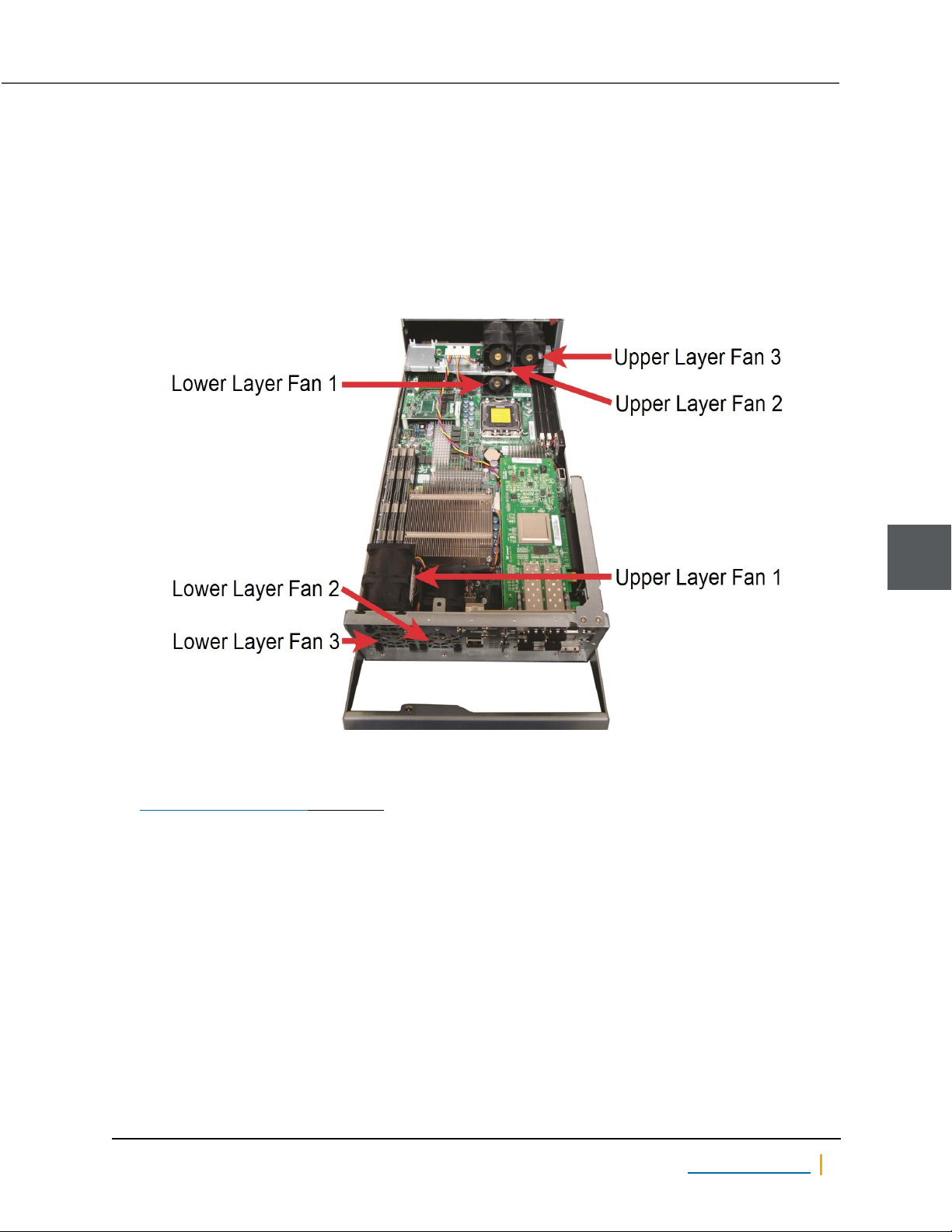
RAID Unity Storage Systems have six fans per controller: three on the motherboard (designated Lower Layer)
and three on raised brackets (designated Upper Layer).
Figure 2-8: Locations of fans in a controller
► To replace an upper layer fan
1. Perform the component identification, migrate cluster resources, and controller removal steps under
System sub-components on page41.
2
Nexsan Unity www.nexsan.com 43
Page 44
Fans
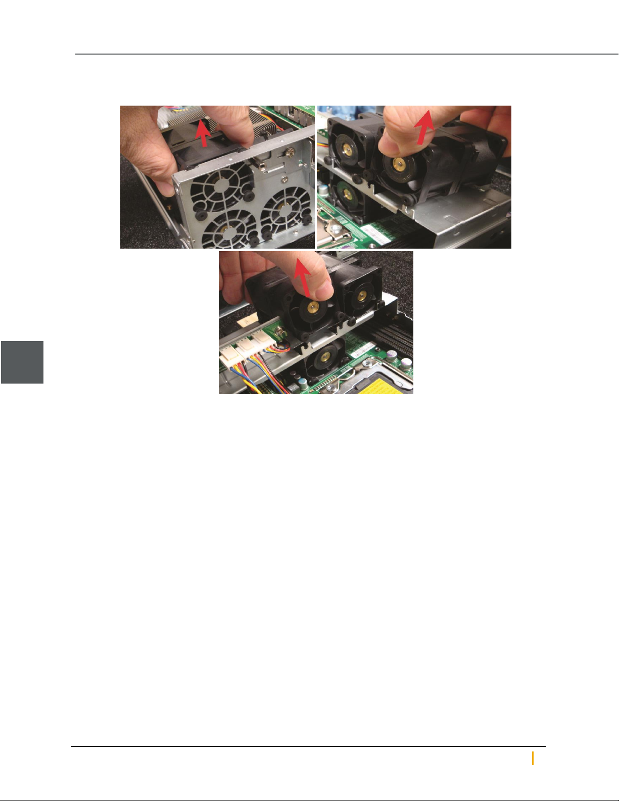
2. Gently lift the fan from its slot.
Figure 2-9: Removing upper layer fans
2
3. If necessary, snip the pull ties holding the fan’s power wires to the chassis.
Nexsan Unity Hardware Maintenance Guide v. 5.1 Unity 44
Page 45
Chapter 2: Customer Replaceable Units: Class 2
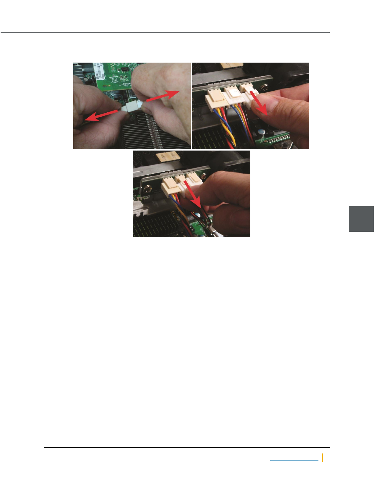
4. Unclip the retaining tab on the power plug and gently remove it from the socket.
Figure 2-10: Disconnecting the fan’s power plug
5. Insert the power plug for the replacement fan into the socket and gently press until the retaining tab
clicks.
6. If necessary, re-secure the power wires with new pull ties.
2
Nexsan Unity www.nexsan.com 45
Page 46
Fans
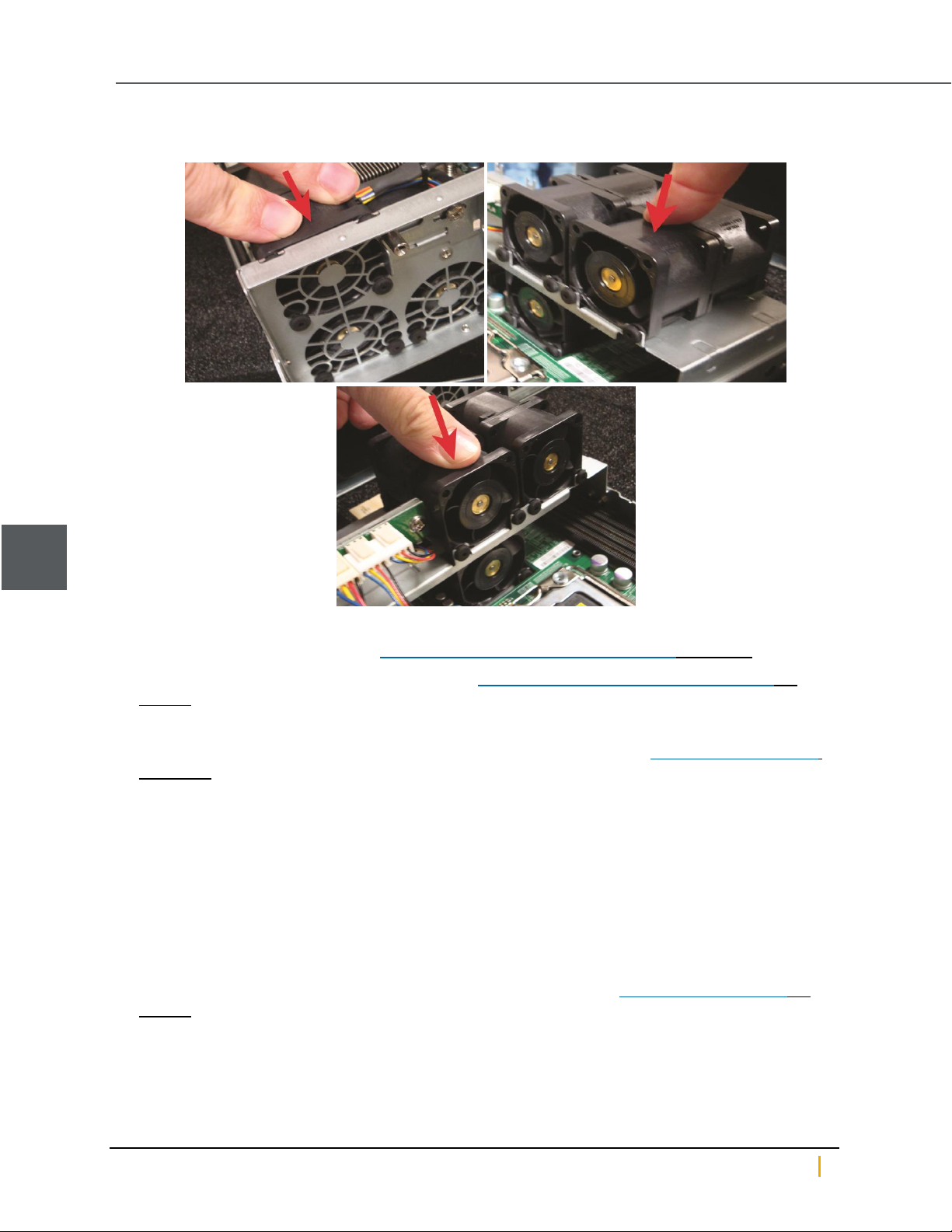
7. Gently place the replacement fan into the slot. Press firmly down to ensure that it is properly seated.
Figure 2-11: Replacing upper layer fans
2
8. Guide the controller into the slot and slide it in until some resistance is met, then push the extraction
handle up to seat the controller. See Replacing a Unity Storage System controller on page54.
9. Re-secure the extraction handle retaining bolt. See Replacing a Unity Storage System controller on
page54.
10. Replace all cables on the new controller.
Notes: Be sure to put all cables back into the proper ports. See Step 4 under System sub-components
on page41.
If the controller does not automatically start up, select it in Unity and click the Turn On button in its
Properties panel at the bottom of the screen.
11. Verify that the new fan is working using the sensors command in the command-line interface (CLI). See
Accessing the nxadmin CLI and Using the nxadmin CLI’s command-based shell in the Nexsan Unity CLI
reference Guide.
12. Migrate the resources back to the controller you removed using Unity. See Moving Cluster Resources in
the Nexsan Unity Software User Guide.
► To replace the lower layer fan 1:
1. Perform the component identification and controller removal steps under System sub-components on
page41.
Nexsan Unity Hardware Maintenance Guide v. 5.1 Unity 46
Page 47
Chapter 2: Customer Replaceable Units: Class 2
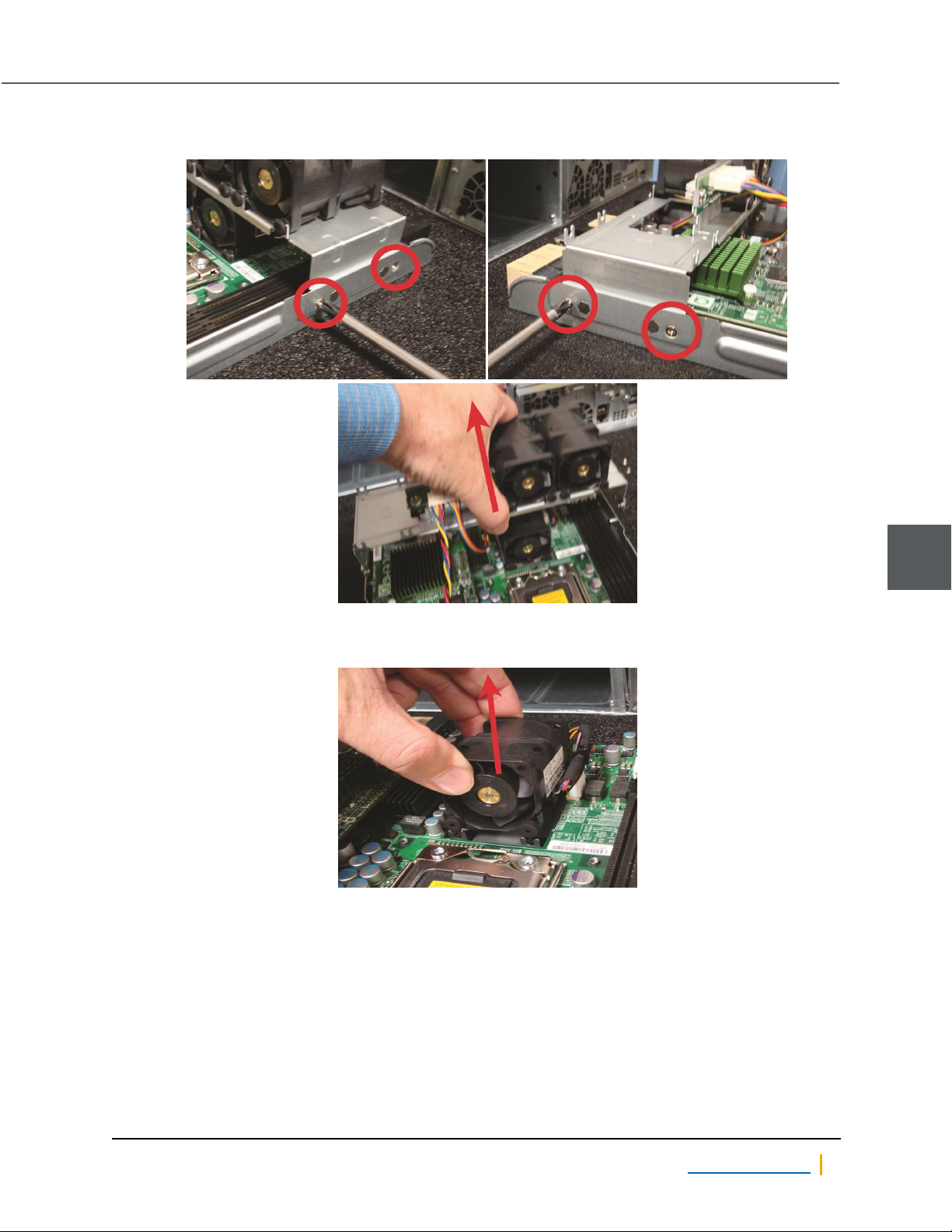
2. Unscrew and remove the bracket holding the upper layer fans in place. Set it aside.
Figure 2-12: Removing the fan bracket
3. Gently lift the fan from its slot.
2
Figure 2-13: Removing Lower Layer Fan 1
Nexsan Unity www.nexsan.com 47
Page 48
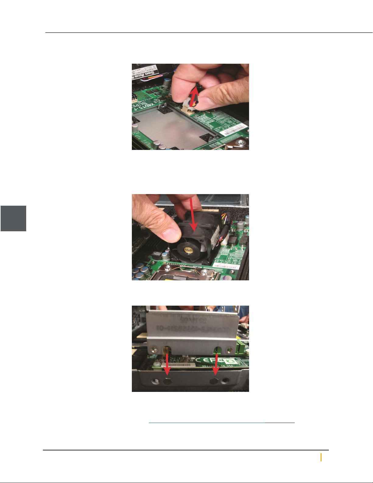
Fans
4. Unclip the retaining tab on the power plug and gently remove it from the socket.
Figure 2-14: Disconnecting the fan’s power plug
5. Insert the power plug for the replacement fan into the socket and gently press until the retaining tab
clicks.
6. Gently place the replacement fan into the slot. Press firmly down to ensure that it is properly seated.
Figure 2-15: Replacing Lower Layer Fan 1
2
7. Line up the notches in the sides of the bracket with the tabs on the controller.
Figure 2-16: Lining up the bracket for replacement
8. Re-secure the bracket with the screws you removed in Step 2.
9. Guide the controller into the slot and slide it in until some resistance is met, then push the extraction
handle up to seat the controller. See Replacing a Unity Storage System controller on page54.
Nexsan Unity Hardware Maintenance Guide v. 5.1 Unity 48
Page 49
Chapter 2: Customer Replaceable Units: Class 2
10. Re-secure the extraction handle retaining bolt. See Replacing a Unity Storage System controller on
page54.
11. Replace all cables on the new controller.
Notes: Be sure to put all cables back into the proper ports. See Step 4 under System sub-components
on page41.
If the controller does not automatically start up, select it in Unity and click the Turn On button in its
Properties panel at the bottom of the screen.
12. Verify that the new fan is working using the sensors command in the command-line interface (CLI). See
Accessing the nxadmin CLI and Using the nxadmin CLI’s command-based shell in the Nexsan Unity CLI
Reference Guide.
13. Migrate the resources back to the controller you removed using Unity. See Moving Cluster Resources in
the Nexsan Unity Software User Guide.
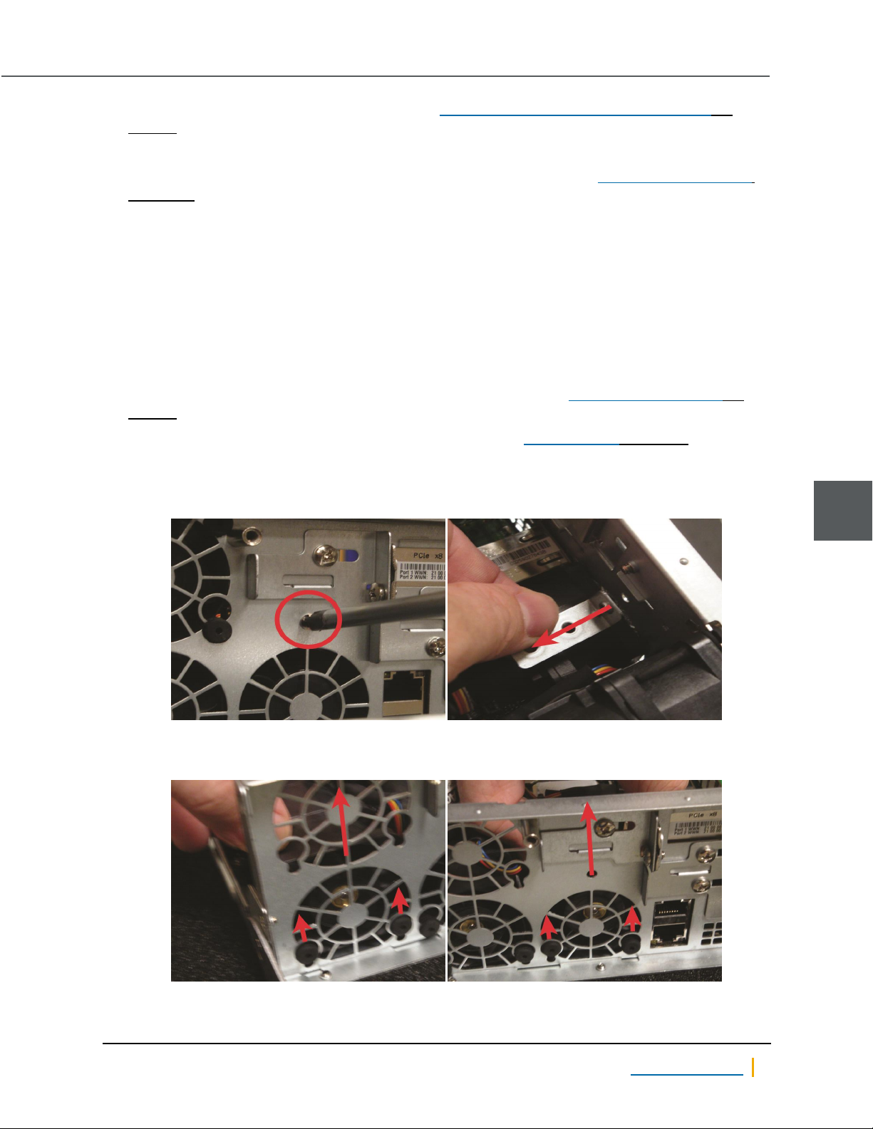
► To replace a lower layer fan 2 or 3 (Unity 2200 or Unity 2200X):
1. Perform the component identification and controller removal steps under System sub-components on
page41.
2. Remove Upper Layer Fan 1, but do not detach it from power (see Replacing a fan on page43, far left
photograph). Set it aside.
3. If necessary, unscrew the fan bracket from the back of the controller and remove it.
Figure 2-17: Removing the fan bracket
4. Gently lift the fan from its slot.
Figure 2-18: Removing Primary Fan 2 or 3
2
Nexsan Unity www.nexsan.com 49
Page 50
2
Fans
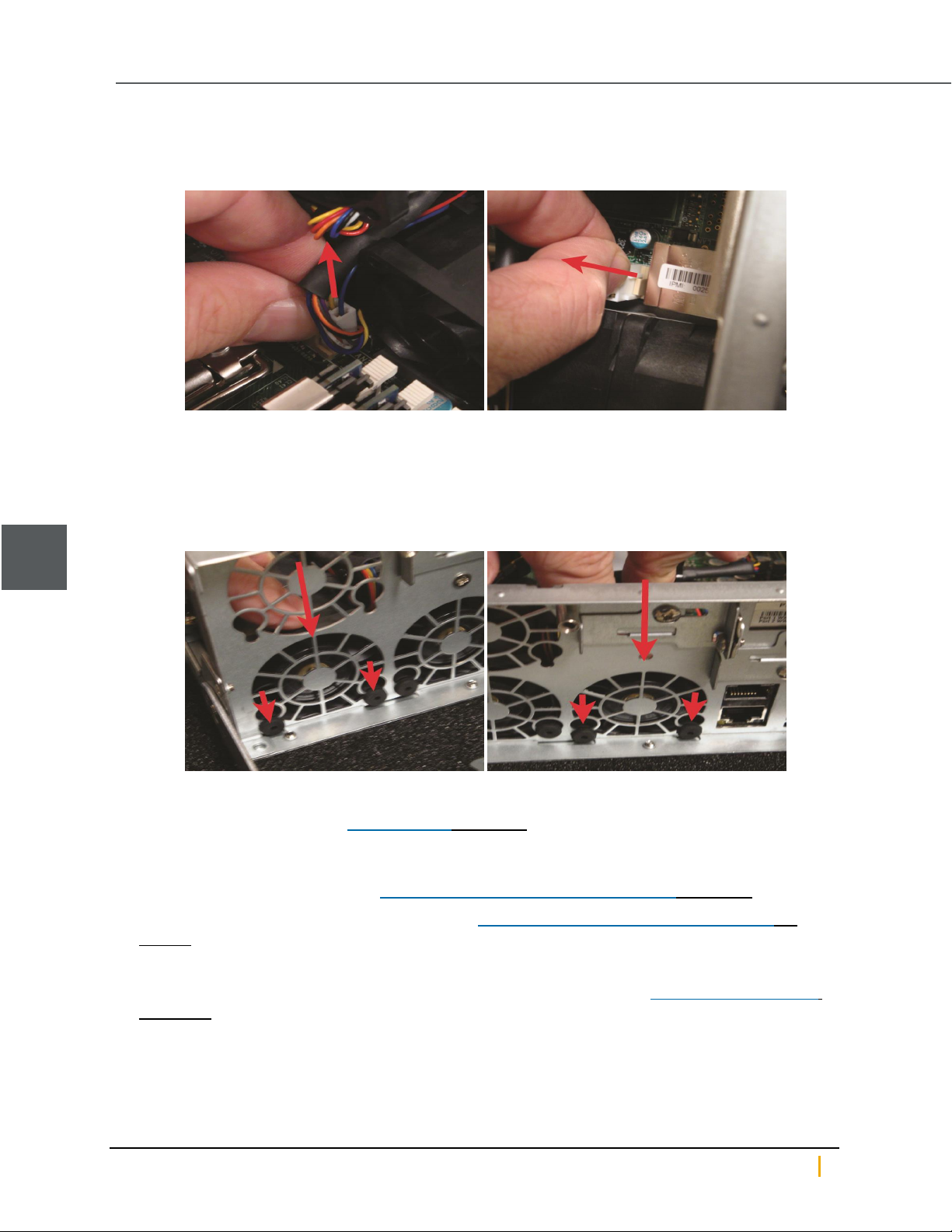
5. Snip the pull ties holding the fan’s power wires to the chassis.
6. Unclip the retaining tab and gently remove the power plug from the socket.
Figure 2-19: Disconnecting the fan’s power plug
7. Insert the power plug for the replacement fan into the socket and gently press until the retaining tab
clicks.
8. Re-secure the power wires with new pull ties.
9. Gently place the replacement fan into the slot. Press firmly down to ensure that it is properly seated.
Figure 2-20: Replacing Primary Fan 2 or 3
10. If necessary, replace the fan bracket.
11. Replace Secondary Fan 1 (see Replacing a fan on page43, far left photograph). Press firmly down to
ensure that it is properly seated.
12. Guide the controller into the slot and slide it in until some resistance is met, then push the extraction
handle up to seat the controller. See Replacing a Unity Storage System controller on page54.
13. Re-secure the extraction handle retaining bolt. See Replacing a Unity Storage System controller on
page54.
14. Replace all cables on the new controller.
Notes: Be sure to put all cables back into the proper ports. See Step 4 under System sub-components
on page41.
If the controller does not automatically start up, select it in Unity and click the Turn On button in its
Properties panel at the bottom of the screen.
Nexsan Unity Hardware Maintenance Guide v. 5.1 Unity 50
Page 51
Chapter 2: Customer Replaceable Units: Class 2
15. Verify that the new fan is working using the sensors command in the command-line interface (CLI). See
the Nexsan Unity nxadmin CLI Reference Guide.
16. Migrate the resources back to the controller you removed using Unity. See Moving Cluster Resources in
the Nexsan Unity Software User Guide.
2
Nexsan Unity www.nexsan.com 51
Page 52

Fans
Nexsan Unity Hardware Maintenance Guide v. 5.1 Unity 52
Page 53

Chapter 3
Chapter 3:Customer Replaceable Units: Class 3
Class 3 CRUs - The following components of the Nexsan Unity Storage Systems are replaceable by the
customer, typically without assistance from Technical Support, but do have a high associated risk of causing
a complete or partial system failure if the documented replacement procedure is not followed correctly. If you
are unsure about a specific step or process, please contact Nexsan Support for assistance.
This chapter contains the following sections:
Unity Storage System controllers 54
3
Nexsan Unity www.nexsan.com 53
Page 54
Unity Storage System controllers
Unity Storage System controllers
When one Unity Storage System controller fails, its resources (Pool Resource Group and storage pools) are
migrated to the remaining Unity Storage System controller automatically.
Replacing a Unity Storage System controller
► To replace a Unity Storage System controller:
1. Shut down the failed controller through Unity. See Shutting down the cluster or individual cluster nodes in
of the Nexsan Unity Software User Guide for details.
2. Remove all cables from the failed controller, being certain to label each with the name and number of the
port to which it was attached.
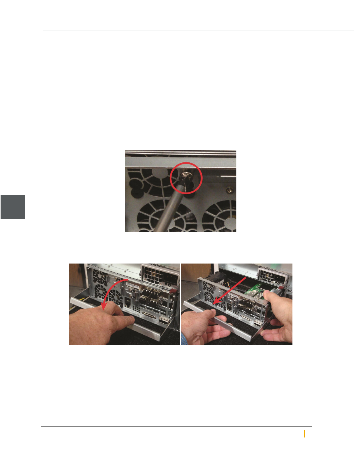
3. Unscrew the retaining bolt on the extraction handle of the controller that needs to be replaced.
Figure 3-1: Unscrewing the controller retaining bolt (standard expansions)
3
4. Pull down the extraction handle to disengage the controller from the unit, then gently pull the controller out
of the chassis, supporting its weight with the other hand.
Figure 3-2: Removing the Unity Storage System controller
Nexsan Unity Hardware Maintenance Guide v. 5.1 Unity 54
Page 55
Chapter 3: Customer Replaceable Units: Class 3
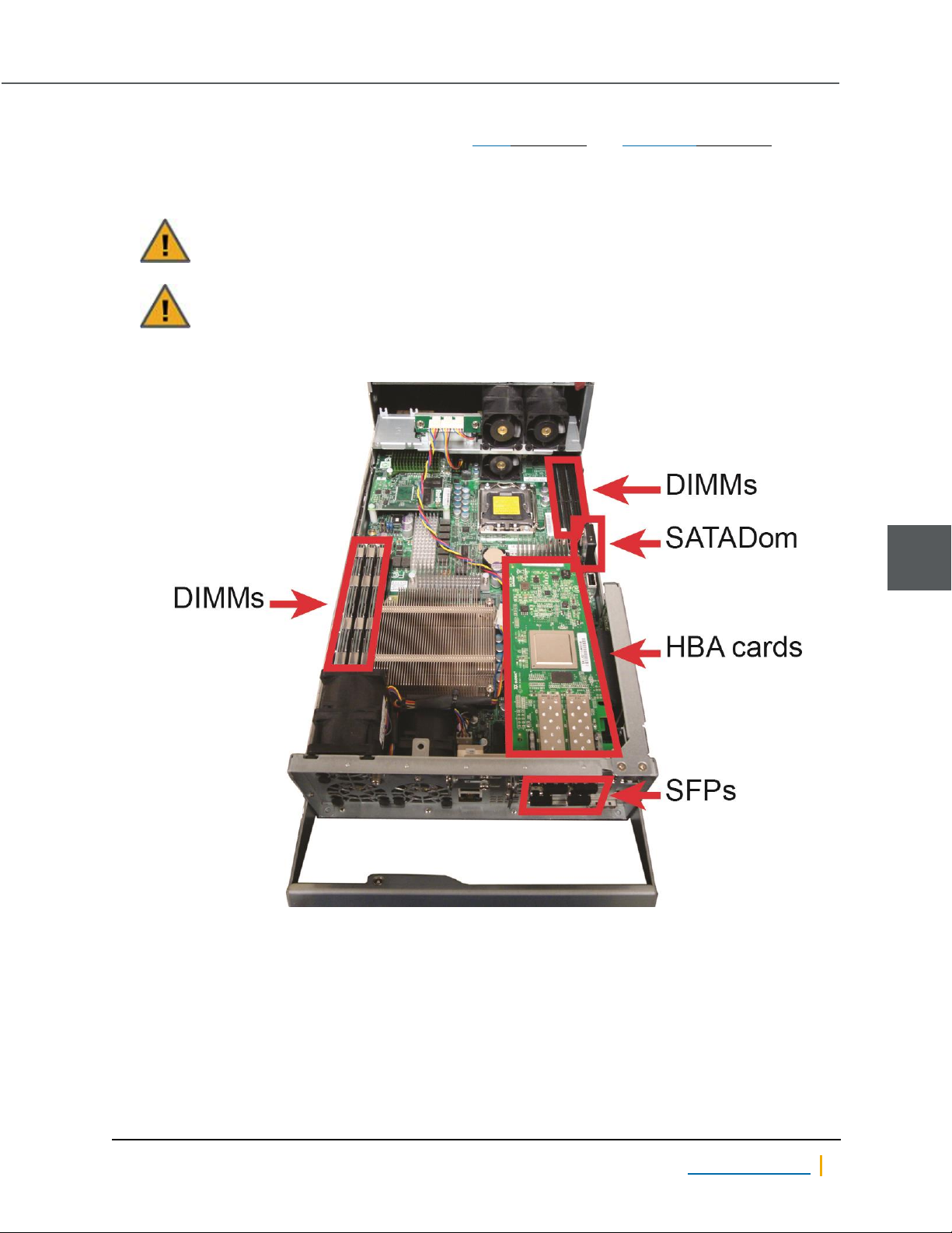
5. Remove all SFPs, HBA cards, DIMMs, and the SATADom from the failed controller and install them into
the same slots on the replacement controller. See SFPs on page33, and SATADom on page72 for
details.
You MUST install the HBA cards into the same slots on the replacement controller as they occupied on
the failed controller.
CAUTION: Be certain to press the metal clip on the side of the SATADom inward to unlatch it
before removing the SATADom. Failure to do so may cause for the clip to break.
CAUTION: Be sure that the SATADom power cable wires are clear of the edge of the
controller. Failure to do so may result in damage to the wires when the controller is replaced.
Figure 3-3: Locations of HBA cards, SFPs, DIMMs, and the SATADom
3
Nexsan Unity www.nexsan.com 55
Page 56
Unity Storage System controllers
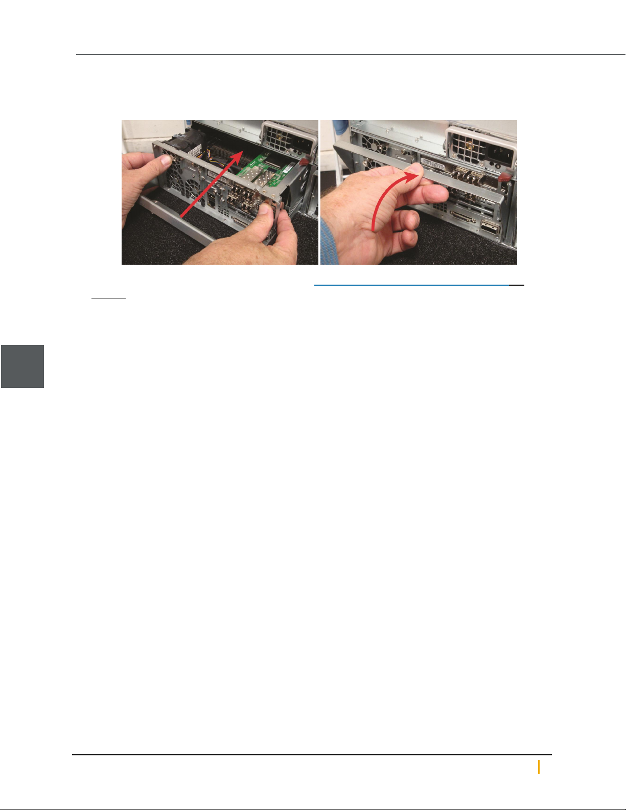
6. Guide the new controller into the slot and slide it in until some resistance is met, then push the extraction
handle up to seat the controller.
Figure 3-4: Inserting the new controller
7. Re-secure the extraction handle retaining bolt. See Replacing a Unity Storage System controller on
page54.
8. Replace all cables on the new controller, being sure to put all cables back into the proper ports. See
Step2.
3
9. Open Unity and verify that the new controller is being recognized by the system. See "Finding Unity
features" in the Nexsan Software User Guide.
Notes: If the controller does not automatically start up, select it inUnity and click the Turn On button in
its Properties panel at the bottom of the screen.
It may take a few minutes for the new controller to fully start up.
10. Reconfigure the IPMI settings for the controller. See "Setting or modifying IPMI settings" in the Nexsan
Unity Software User Guide.
11. Migrate the failed controller’s resources to the new controller in Unity. See Moving Cluster Resources in
the Nexsan Unity Software User Guide.
Nexsan Unity Hardware Maintenance Guide v. 5.1 Unity 56
Page 57

Chapter 4
Chapter 4:Support-Assisted FRUs: Class 2
Class 2 Support-Assisted FRUs - The following components of the Nexsan Unity Storage Systems are
replaceable only with assistance from Nexsan Support as they have some associated risk of causing a
complete or partial system failure. Please contact Nexsan Support if one of the following components has
failed.
This chapter contains the following sections:
DIMMs 58
Identifying a failed DIMM 58
4
Nexsan Unity www.nexsan.com 57
Page 58
4
DIMMs
DIMMs
Dual in-line memory modules (DIMMs) supply the random-access memory (RAM) for Unity. In cases of
failure, they can be replaced.
Note A failed DIMMaffects the entire controller, but replacement of a DIMMcan only be done by Nexsan
Support Group. Please contact Nexsan Support immediately if you suspectz a failed DIMM in your Unity
Storage Systems.
Identifying a failed DIMM
DIMM failure can be difficult to diagnose without the assistance of Nexsan Support; however, the following
may help you identify a potentially failed DIMM:
If you have autolog enabled, the analyzer will likely detect a failed DIMM.
If you are familiar with the amount of RAMthat you have, run the top command in the command line
interface (CLI)to see if the amount is lower than you think it should be. See Accessing the nxadmin CLI
and Using the nxadmin CLI’s command-based shell in the Unity CLI Reference Guide. You can also check
if the amount of RAMis comparatively lower than the other controller.
A failed DIMM often causes a drop in the system's performance.
Note It is possible for DIMMs to only partially fail. In this case, the top command in the nxadmin CLI may not
show lower RAMlevels and there may not be a visible drop in performance. However, seemingly random
failures and system crashes will likely still occur and are important signs of DIMM failure.
If you suspect DIMM failure, contact Nexsan Support for assistance.
Nexsan Unity Hardware Maintenance Guide v. 5.1 Unity 58
Page 59

Chapter 5
Chapter 5:Support-Assisted Replacements: Class 3
Class 3 Support-Assisted FRUs - The following components of the Nexsan Unity Storage Systems are
replaceable only by qualified Nexsan Support personnel as they have a high associated risk of causing a
complete or partial system failure. Please contact Nexsan Support if one of the following components has
failed.
This chapter contains the following sections:
Chassis 60
System SSDs 64
SATADom 72
5
Nexsan Unity www.nexsan.com 59
Page 60
Chassis
Chassis
Use this procedure to diagnose whether the Unity System has a failed chassis.
Identifying a failed chassis
Only Nexsan Support is able to officially diagnose a chassis as failed. If you suspect a failed chassis please
first ensure that no other component may be responsible for the failure; see:
Identifying failed disk drives on page11
Identifying a failed DIMM on page58
Identifying a failed controller on page36
If you have eliminated the possibility of failure in any other component, please contact Nexsan Support for
assistance.
Replacing a chassis
This procedure is only to be followed if the chassis was officially diagnosed as failed by Nexsan Support. For
more information, see Identifying a failed chassis above.
► To remove a chassis:
CAUTION: A minimum of two people are required for safe removal and replacement of the chassis.
5
1. Shut down both controllers using Nexsan Unity. See "Shutting down the cluster or individual cluster
nodes" in the Nexsan Unity Software User Guide for details.
2. Remove all cables, being certain to label each with the name and number of the port to which it was
attached.
3. Remove both controllers from the failed chassis. Take note of the positioning of the controllers.
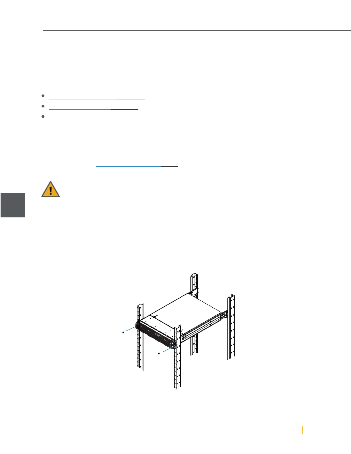
4. Remove the thumbscrews that hold the front of the chassis to the rack.
Figure 5-1: Example - Removing thumbscrews
Nexsan Unity Hardware Maintenance Guide v. 5.1 Unity 60
Page 61
Chapter 5: Support-Assisted Replacements: Class 3
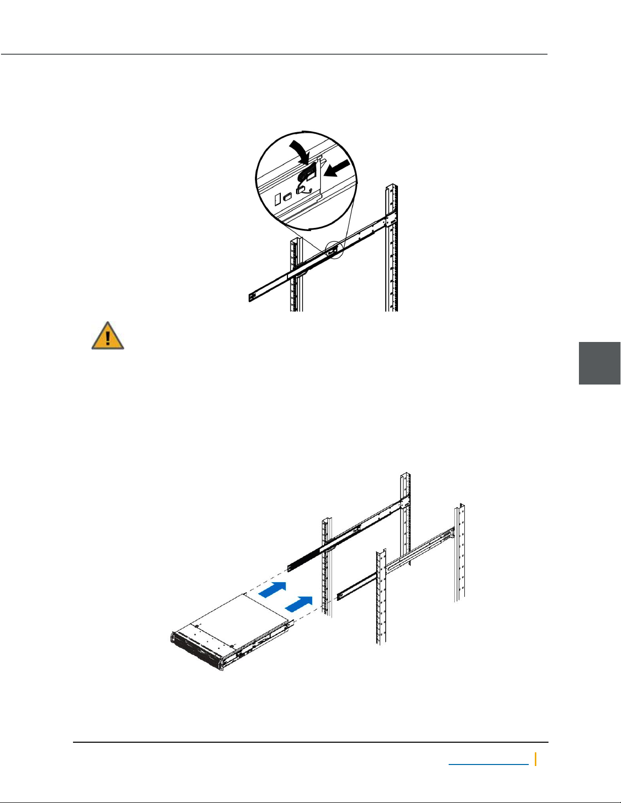
5. To remove the chassis, slide the inner-chassis rails from the outer-rack rails ensuring equal pressure on
both rails. You may have to press the locking tabs to release the chassis, prior to sliding. Place the
chassis aside.
Figure 5-2: Example - Locking tabs
CAUTION: Do not pick up the server by the front handles, they are only designed to pull the
chassis from the rack.
Note As replacement chassis ship with chassis rails pre-installed, it is not necessary to remove the chassis
rails from the old chassis.
► To install a replacement chassis:
1. Lift the chassis from each side—not from the front or back.
2. Line up the inner-chassis rails with the front of the outer-rack rails.
Figure 5-3: Example - Installing a chassis
5
Nexsan Unity www.nexsan.com 61
Page 62
5
Chassis
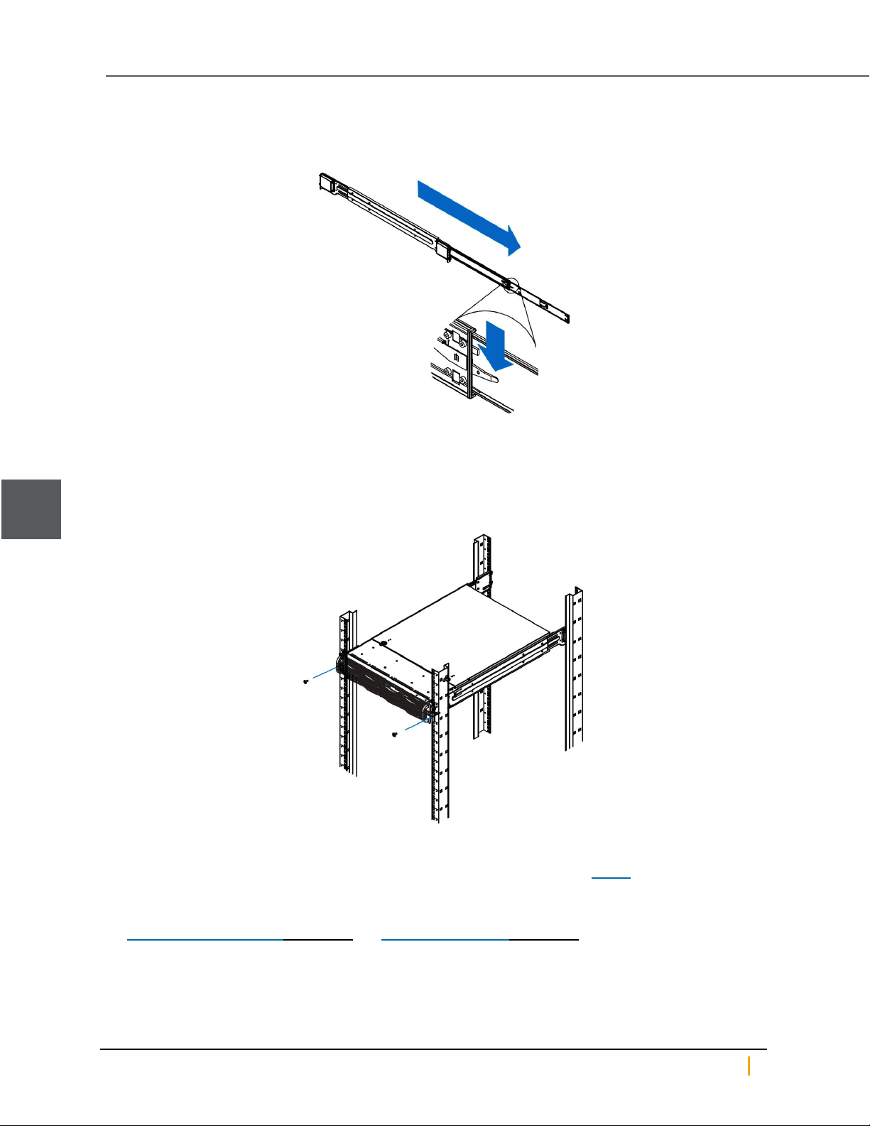
3. Slide the inner-chassis rails into the outer-rack rails, keeping the pressure even on both sides. Depress
the locking tabs when inserting.
Figure 5-4: Example - Depressing the rail locking tabs
4. Push the chassis completely into the rack. You should hear the locking tabs "click"when in position.
5. Tighten the thumbscrews that hold the front of the chassis to the rack.
Note The thumbscrews are already attached to the front of the chassis.
Figure 5-5: Example - Tightening the thumbscrews
6. Install both controllers into the same slots in the replacement chassis as the old chassis.
7. Replace all cables, ensuring that they are put back into the proper ports. See Step 2 of To remove a
chassis.
8. Transfer the disk drives from the old chassis to the replacement chassis in the same configuration. See
Replacing FASTier drives on page22 and Replacing data disks on page18.
Nexsan Unity Hardware Maintenance Guide v. 5.1 Unity 62
Page 63
Chapter 5: Support-Assisted Replacements: Class 3
9. Open Nexsan Unity and verify that both controllers are being recognized by the system. Click Cluster
Status in the Unity Dashboard for more options.
Notes: If the controllers do not automatically start up, select each controller in Unity and click the Turn
On Controller button.
It may take a few minutes for the controllers to fully start-up.
5
Nexsan Unity www.nexsan.com 63
Page 64
System SSDs
System SSDs
Unity Storage Systems have two internal solid-state disks (SSDs): One FASTier write cache SSD and one
drive used for the Unity operating system (the OS SSD).
See:
Replacing the FASTier Cache SSD below
Replacing the OS SSD on page68
Replacing the FASTier Cache SSD
The FASTier Cache SSD replacement procedure involves both software and hardware steps. It is necessary
that you perform these procedures with assistance by Technical Support, see Contacting Nexsan on page7.
Note The FASTier Write Cache SSD is the drive that is attached to the SATA1 port.
► To replace a FASTier Cache SSD drive:
1. Contact Technical Support and have them prepare your Unity for the SSDreplacement.
2. Perform the migrate cluster resources, unit shutdown, and cover removal steps under System sub-
components on page41.
Note If the FASTier data cables are not fed through the plastic guides on the top of the clear plastic disk
shelf, proceed to step 4.
5
Nexsan Unity Hardware Maintenance Guide v. 5.1 Unity 64
Page 65
Chapter 5: Support-Assisted Replacements: Class 3
3. Unplug the FASTier data cables from the motherboard and slide them out of the plastic guides on top of
the shelf.
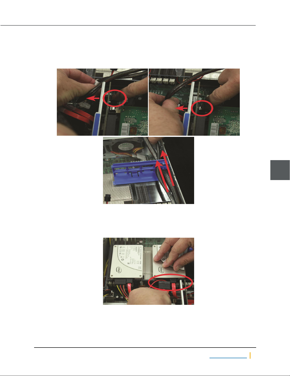
Note Label each cable with the port it was plugged into so that it can be replaced in the proper plug when
you are finished.
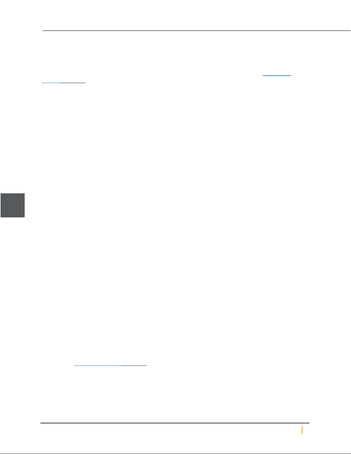
Figure 5-6: Unplugging FASTier cords and sliding them out of the plastic guides
4. Remove the power and data cables from the cache SSD drive.
Note Label each power and data cable with the drive from which it was removed so that it can be properly
replaced when you are finished.
Figure 5-7: Unplugging OS SSD drive
5
Nexsan Unity www.nexsan.com 65
Page 66
System SSDs
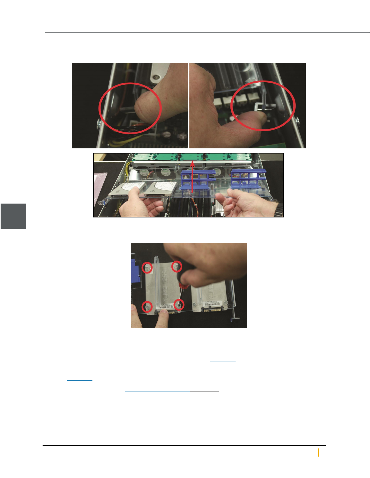
5. Unlatch the shelf on either side and remove it.
Figure 5-8: Removing the plastic shelf
5
6. Turn the shelf over and unscrew the old cache SSD drive to remove it.
Figure 5-9: Removing the old cache SSD drive
7. Attach the new cache SSD drive to the shelf.
8. Place the plastic shelf back into the unit (see Figure 5-8).
9. Re-attach the power and data cables to the cache SSD (see Figure 5-7).
10. Thread the FASTier data cables back through the plastic guides and re-attach them to the motherboard
(see Figure 5-6).
11. Replace the top cover (see System sub-components on page41) and secure it with the cover screws
(see System sub-components on page41).
12. Return the unit to the rack.
Nexsan Unity Hardware Maintenance Guide v. 5.1 Unity 66
Page 67
Chapter 5: Support-Assisted Replacements: Class 3
13. Replace all communication cables on the unit.
Note Be sure to put all cables back into the proper ports. See Step 4 under System sub-components on
page41.
14. Re-attach the power cables to the power supply units (PSUs) to turn the unit back on.
15. Allow Technical Support to configure the new battery-backed cache SSDdisk.
5
Nexsan Unity www.nexsan.com 67
Page 68
System SSDs
Replacing the OS SSD
The OS SSD replacement procedure involves both software and hardware steps. To make the process
easier, it has been divided into five sections.
It is necessary that you perform these procedures with Technical Support assistance. See Contacting
Nexsan on page7 for telephone numbers and email addresses for your region.
Record system settings
Some system settings must be reconfigured after the OS SSD is replaced. It is necessary, therefore, to write
these settings down so that they can be properly re-entered later.
► To record system settings:
1. Ensure that IPMI is properly configured on the unit, and write down the IPMI settings:
a. On the Unity Dashboard, click Cluster Status.
b. Click Status >IPMI.
c. Make sure that the IPMI settings are configured; if they are not, you must configure them, including
assigning an IPMI address to each controller node.
d. Write down all IPMI settings.
5
2. Write down all IP and network settings:
a. On the Unity Dashboard, click Cluster Status.
b. Click Status >IP Configuration.
c. Write down all IP and network settings.
3. Determine which node is the active node and which is the passive node.
Note Although both controller nodes in the Active/Active Cluster implementation are “active”, the
controller node that is currently hosting the cluster management services is considered the active
controller by the system. It's best to replace the OS SSD on the passive node first, and then replace the
OS SSD on the active node.
a. Open a separate SSH session to each node.
b. On each node, log on as nxadmin.
c. When the command prompt appears, type menu, then press the Enter key.
d. When the main menu is displayed, type 2 (Shutdown and Reboot Menu), then press the Enter key.
e. Type 8 (Power Control Menu...) and press the Enter key.
f. Type 2 (Show Status) and press the Enter key to display the node’s status, either active or passive.
Back up the old OS SSD
The operating system and system configuration reside on the OS SSD. It is therefore necessary to copy this
information from the old OS SSD to the new one. However, this process can only be done by Technical
Support, see Contacting Nexsan on page7.
When Technical Support has finished backing up the OS SSD, you may then continue with the next
procedure.
Install the new OS SSD
Note The OS SSD is the drive that is attached to the SATA0 port.
Nexsan Unity Hardware Maintenance Guide v. 5.1 Unity 68
Page 69
Chapter 5: Support-Assisted Replacements: Class 3
► To remove the old OS SSD and install the new one:
1. Perform the unit shutdown and cover removal steps under System sub-components on page41.
Note If the FASTier data cables are not fed through the plastic guides on the top of the clear plastic disk
shelf, proceed to step 3.
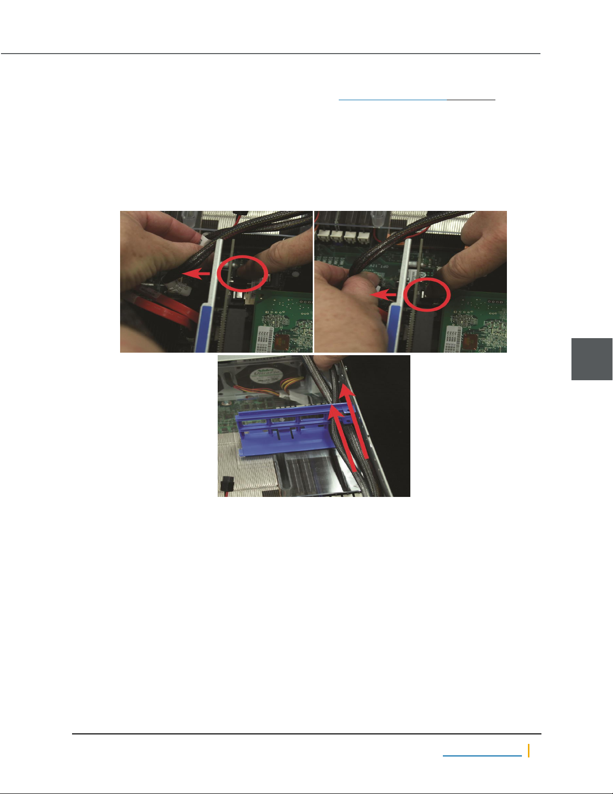
2. Unplug the FASTier data cables from the motherboard and slide them out of the plastic guides on top of
the shelf.
Note Label each cable with the port it was plugged into so that it can be replaced in the proper plug when
you are finished.
Figure 5-10: Unplugging FASTier cords and sliding them out of the plastic guides
5
Nexsan Unity www.nexsan.com 69
Page 70
System SSDs
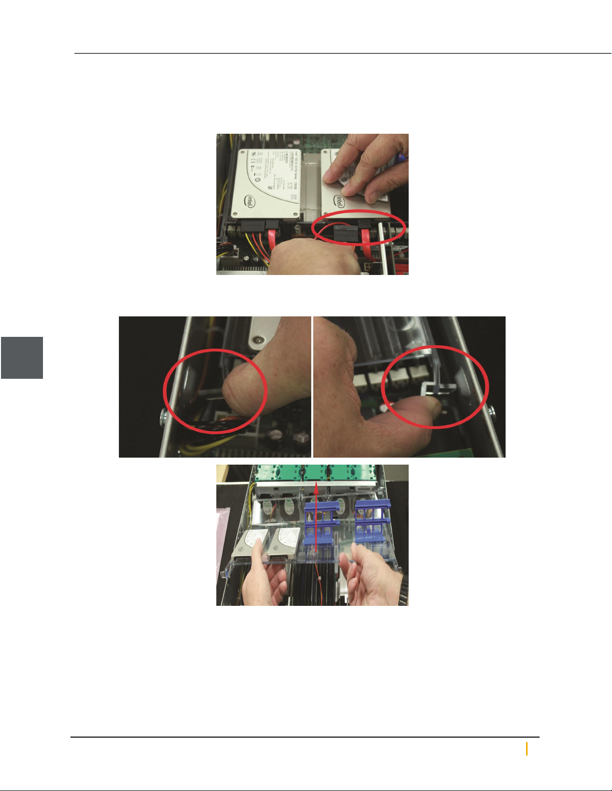
3. Remove the power and data cables from the OS SSD drive.
Note Label each power and data cable with the drive from which it was removed so that all cables can be
correctly replaced when you are finished.
Figure 5-11: Unplugging OS SSD drive
4. Unlatch the shelf on either side and remove it.
Figure 5-12: Removing the plastic shelf
5
Nexsan Unity Hardware Maintenance Guide v. 5.1 Unity 70
Page 71
Chapter 5: Support-Assisted Replacements: Class 3
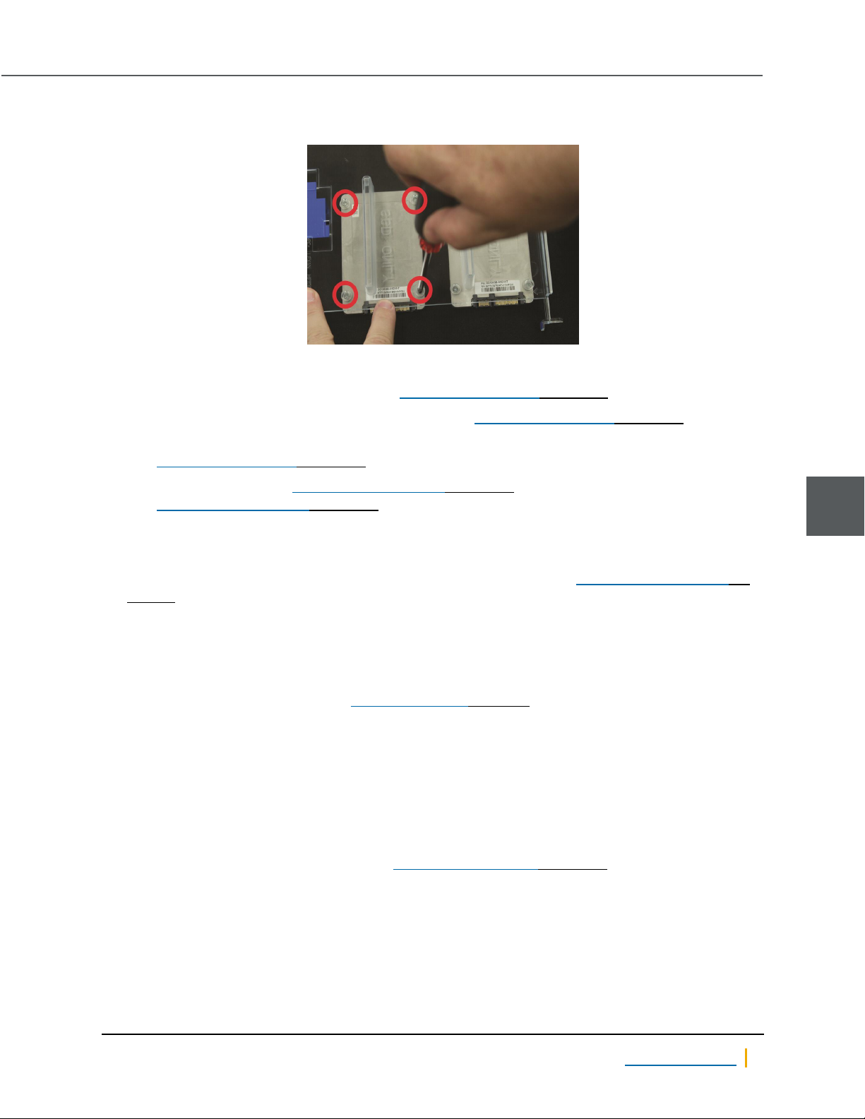
5. Turn the shelf over and unscrew the old OS SSD drive to remove it.
Figure 5-13: Removing the old OS SSD drive
6. Attach the new OS SSD drive to the shelf.
7. Place the plastic shelf back into the unit (see Replacing the OS SSD on page68).
8. Re-attach the power and data cables to the OS SSD (see Replacing the OS SSD on page68).
9. Thread the FASTier data cables back through the plastic guides and re-attach them to the motherboard
(see Replacing the OS SSD on page68).
10. Replace the top cover (see System sub-components on page41) and secure it with the cover screws
(see System sub-components on page41).
11. Return the unit to the rack.
12. Replace all communication cables on the unit.
Note Be sure to put all cables back into the proper ports. See Step 4 under System sub-components on
page41.
13. Re-attach the power cables to the power supply units (PSUs) to turn the unit back on.
Transfer data to the new OS SSD
When the passive controller comes back online, Technical Support must then transfer data to the new OS
SSD. To contact Technical Support, see Contacting Nexsan on page7.
When the OS SSD data has been restored, you may then continue to the next procedure.
Re-enter IPMI settings
► To re-enter IPMI settings for the restored controller:
1. On the Unity Dashboard, click Cluster Status.
2. Click Status >IPMI.
3. Using the settings you recorded in Step 1 of Record system settings on page68, re-enter the IPMI
settings for this unit.
5
Nexsan Unity www.nexsan.com 71
Page 72
5
SATADom
Replace and restore the OS SSD on the other unit
You must now replace the OS SSD, reconfigure IP and network settings, and restore the operating system
and system configuration on the other unit.
► To replace and restore the OS SSD on the other unit:
1. Perform the unit shutdown and cover removal steps under System sub-components on page41.
2. When the unit is shut down, perform the procedures under Install the new OS SSD on page68, Transfer
data to the new OS SSD on the previous page, and Re-enter IPMI settings on the previous page for the
unit.
SATADom
The SATADom (Serial ATA Disk on Module) replacement procedure involves both software and hardware
steps, and must be performed on both controllers in a clustered environment.
The process has been divided into the following sections:
Replacing a SATADom below
It is necessary that you perform these procedures with the assistance of Technical Support, see Contacting
Nexsan on page7.
Replacing a SATADom
Each Unity Storage System controller has one 16GB OSSATADom.
If an OS SATADom fails, the controller will become unresponsive. If you suspect a failed OSSATADom,
please contact Technical Support to make an official diagnosis, see Contacting Nexsan on page7.
► To record system settings:
In some instances, system settings must be reconfigured after the SATADom is replaced. It is therefore
important to write these settings down so that they can be properly re-entered after installation.
Ensure that IPMI is properly configured on the unit, and write down the IPMI settings:
1. On the Unity Dashboard, click Cluster Status.
2. Click Status >IPMI.
3. Make sure that the IPMI settings are configured; if they are not, you must configure them, including
assigning an IPMI address to each controller node.
4. Write down all IPMI settings.
Nexsan Unity Hardware Maintenance Guide v. 5.1 Unity 72
Page 73
Chapter 5: Support-Assisted Replacements: Class 3
5. On a clustered system, determine which controller node is the active node and which is the passive
node.
Note Although both controller nodes in the Active/Active Cluster implementation are “active”, the
controller node that is currently hosting the cluster management services is considered the active
controller by the system. If you are replacing SATADoms on both controllers, you should replace the
SATADom on the passive controller first, and then replace the SATADom on the active controller.
a. Open a separate SSH session to each controller node.
b.
On each node, log on as nxadmin.
c. When the command prompt appears, type menu, then press the Enter key.
d. When the main menu is displayed, type 2 (Shutdown and Reboot Menu), then press the Enter key.
e. Type 8 (Power Control Menu...) and press the Enter key.
f. Type 2 (Show Status) and press the Enter key to display the node’s status, either active or passive.
g. Type 1 (Show Location) and press the Enter key to display the position of the controller in the
chassis; for example, Left side of chassis from front, slot 01.
► To back up the old SATADom:
The operating system and system configuration reside on the SATADom. It is therefore necessary to copy
this information from the old SATADom to the new one. This process can only be done by Technical Support,
see Contacting Nexsan on page7.
Once Technical Support has completed backing up the SATADom, you may continue with the following
procedures.
5
► To remove and replace the SATADom:
1. Remove the controller from the system. See Unity Storage Expansion controllers on page36 for
directions.
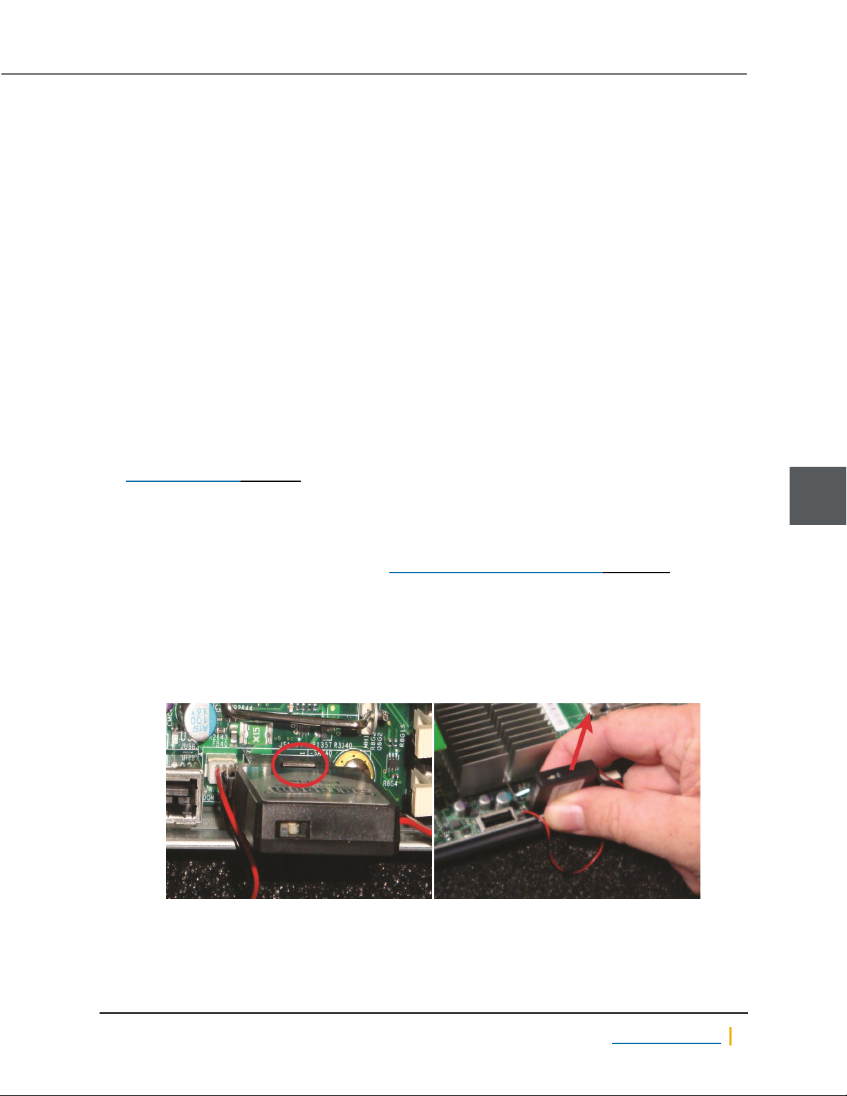
2. Press the small, metal latch near the base of the SATADom, then gently remove the SATADom from the
socket.
Note The SATADom may be hard to remove. Do NOT force it, but gently oscillate it from side to side
until it comes out.
Figure 5-14: Removing the old SATADom
Nexsan Unity www.nexsan.com 73
Page 74
SATADom
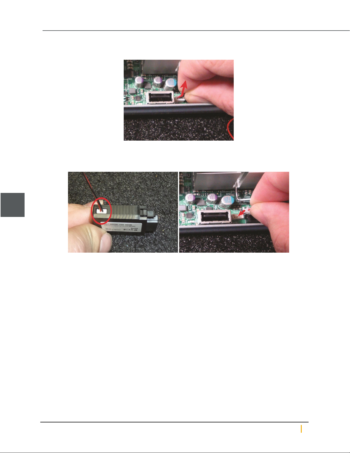
3. Remove the SATADom power cable from the board next to the SATADom socket.
Figure 5-15: Removing the SATADom’s power cable
4. Attach the new SATADom to its power cable, then plug the new SATADom power cable into the socket
on the board.
Figure 5-16: Connecting the new SATADom power cord
5
Nexsan Unity Hardware Maintenance Guide v. 5.1 Unity 74
Page 75
Chapter 5: Support-Assisted Replacements: Class 3
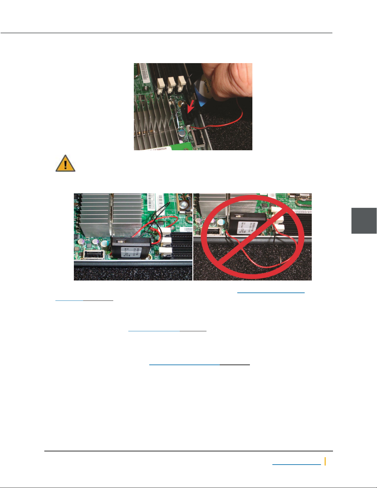
5. Gently plug the new SATADom into the socket until the latch clicks.
Figure 5-17: Inserting the new SATADom
CAUTION: Be sure that the SATADom power cable wires are clear of the edge of the
controller. Failure to do so may result in damage to the wires when the controller is replaced.
Figure 5-18: Power cable placement, good (left) and bad (right)
6. Slide the controller back into the chassis and reattach all cables. See Unity Storage Expansion
controllers on page36 for directions.
► To transfer data to the new SATADom:
When the controller comes back online, Technical Support must then transfer data to the new SATADom. To
contact Technical Support, see Contacting Nexsan on page7.
► To re-enter IPMI settings for the restored controller:
1. On the Unity Dashboard, click Cluster Status.
2. Click Status >IPMI. See Step 1 of To record system settings: on page72.
3. Using the IPMIsettings you wrote down, re-enter the IPMI settings for this controller.
5
Nexsan Unity www.nexsan.com 75
Page 76

Nexsan Head quarters
325 E. Hillcrest Drive, Suite #150
Thousand Oaks, CA 91360
United States of America
Nexsan Can ada
1405 Trans Canada Highway, Suite 300
Dorval, QC H9P 2V9
Canada
Nexsan Ship pin g
302 Enterprise Street , Suite A
Escondido, CA 92029
United States of America
Nexsan Unity Docu ments & Downlo ads pag e:
https://helper.nexsansupport.com/unt_support
Worldwide Web
www.nexsan.com
Copyright © 2010-2018 Nexsan Technologies,Inc. All Rights Reserved.
Nexsan® is a trademark or registered trademar k of Nexsan Technologies, Inc.
The Nexsan logo is a registered trademark of Nexsan Technologies,Inc.
Allother trademarks and registered trademarks are the property of their
respective owner s.
Document Reference:20190102AM113646
Nexsan UK
Units 33–35, Parker Centre, Mansfield Road
Derby, DE21 4SZ
United Kingdom
Nexsan Unity support:
https://helper.nexsansupport.com/unt_support
This pr oduct isprotected by one or more of the following patents, and other
pending patent applications worldwide:
United States patents US8,191,841, US8,120,922;
United Kingdom patents GB2466535B, GB2467622B, GB2467404B,
GB2296798B, GB2297636B
 Loading...