

Nexo NXtension-ES User Manual
NXtension Expander Board
NXtension-ES
ES Monitor Software
User Manual

IMPORTANT SAFETY INSTRUCTIONS
Declaration of conformity
This equipment has been tested and found to comply with the safety objectives and essential requirements of European
(73/23/EEC and 89/336/EEC directives) and international Standards, by fulfilling the requirements of the following
harmonized standards:
Electrical Safety (EU) : IEC 60065 (12/2001) Audio, video and similar electronic apparatus
Electrical Safety (US) : UL60065 Seventh Edition, dated June 30, 2003 category AZSQ, E241312.
Electrical Safety (CAN) : CSA-C22.2 N°60065:03 Edition, dated April 2003 category AZSQ7, E241312
10CE
A
udio Equipment
10CE
A
udio Equipment
Electrical Safety (Rest of the World) : CB test certificate DK-8371 based on IEC60065-2001 7nd ed. with all national
deviations.
Radiated Emission (EU) : EN55103-1 (1996) Electromagnetic compatibility - Product family standard for audio, video,
audio-visual and entertainment lighting control apparatus for professional use.
Radiated Emission (US) : FFC part15 class B
Radiated Emission (CAN) : This Class B digital apparatus complies with Canadian ICES-003.
RF Immunity (EU) : EN55103-2 (1996) Electromagnetic compatibility - Product family standard for audio, video, audiovisual and entertainment lighting control apparatus for professional use.
Note: EMC conformance testing is based on the use of recommended cable types. The use of other cable types may
degrade EMC performances.
IMPORT ANT SAFETY INSTRUCTIONS
1) Read these instructions.
2) Keep these instructions.
3) Heed all warnings.
4) Follow all instructions.
5) Do not use this apparatus near water.
6) Clean only with dry cloth.
7) Do not block any ventilation openings. Install in accordance
with the manufacturer’s instructions.
8) Do not install near any heat sources such as radiators, heat
registers, stoves, or other apparatus (including amplifiers) that
produce heat.
9) Do not defeat the safety purpose of the polarized or groundingtype plug. A polarized plug has two blades with one wider than
the other. A grounding type plug has two blades and a third
grounding prong. The wide blade or the third prong are provided
for your safety. If the provided plug does not fit into your outlet,
consult an electrician for replacement of the obsolete outlet. (US
market)
10) Protect the power cord from being walked on or pinched
particularly at plugs, convenience receptacles, and the point
where they exit from the apparatus.
11) Only use attachments/accessories specified by the
manufacturer.
13) Unplug this apparatus during lightning storms or when unused
for long periods of time.
14) Refer all servicing to qualified service personnel. Servicing is
required when the apparatus has been damaged in any way, such
as power-supply cord or plug is damaged, liquid has been spilled
or objects have fallen into the apparatus, the apparatus has been
exposed to rain or moisture, does not operate normally, or has
been dropped.
Information about products that generate electrical
noise :
NOTE: The United States Federal Communications
Commission (in 47 CFR 15.105) has specified that the following
notice be brought to the attention of users of this product:
This equipment has been tested and found to comply with the
limits for a Class B digital device, pursuant to Part 15 of the
FCC Rules. These limits are designed to provide reasonable
protection against harmful interference in a residential
installation. This equipment generates, uses and can radiate
radio frequency energy and, if not installed and used in
accordance with the instructions, may cause harmful
interference to radio communications. However, there is no
guarantee that interference will not occur in a particular
installation. If this equipment does cause harmful interference to
radio or television reception, which can be determined by
turning the equipment off and on, the user is encouraged to try
to correct the interference by one or more of the following
measures:
- Reorient or relocate the receiving antenna.
- Increase the separation between the equipment and receiver.
- Connect the equipment into an outlet on a circuit different from
that to which the receiver is connected.
- Consult the dealer or an experienced radio/TV technician for
help.
The user may find the following booklet, prepared by the
Federal Communications Commission, helpful: How to identify
and Resolve Radio/TV Interference Problems. This booklet is
available from the U.S. Government Printing Office,
Washington, D.C. 20402, Stock No. 004-000-00345-4. Use of a
shielded cable is required to comply within Class B limits of Part
15 of FCC Rules. Pursuant to Part 15.21 of the FCC Rules, any
changes or modifications to this equipment not expressly
approved by NEXO S.A. may cause, harmful interference and
void the FCC authorization to operate this equipment.
To avoid electrical shock, do not remove covers.
Dangerous voltages exist inside.
Refer all servicing to qualified personnel only.
WARNING: To reduce the risk of fire or electric shock,
do not expose this apparatus to rain or moisture.
RISK OF ELECTRIC SHOCK
DO NOT OPEN
CAUTION
The lightning flash with arrowhead
symbol, within an equilateral triangle
is intended to alert the user to the
presence of uninsulated “dangerous
voltage” within the product's
enclosure that may be of sufficient
magnitude to constitute a risk of
electric shock to persons.
The exclamation point within an
equilateral triangle is intended to
alert the user to the presence of
important operating and
maintenance (servicing) instructions
in the literature accompanying
the appliance.
NXTENSION USER MANUAL
DOCUMENT REVISION 150305
PAGE 2

KNOWN BUGS & SOFTWARE ISSUES (15 MAR 05)
Known bugs & software issues (15 mar 05)
The software that you are going to install is the result of two months of field
optimization. However it’s status is still a PRE-release status and it contains still some
minor bugs & features that have not been fixed yet (and which may be described as
working in the following pages).
Please check our website
www.nexo-sa.com periodically for updates.
Please report bugs and feature requests to
technical@nexo.fr
ESmonitor Software
The Input VU meters don’t indicate red when clipping. The orange zone of the vu-meter is
not at -12dB. but earlier. Amplifier clipping is not represented on output VU meter.
Changing setup: C&F key combination for accessing different cabinet families is not yet
implemented. The software will issue a warning that you are changing family instead.
Protection monitoring is not implemented.
Firmware update via the network is not implemented.
Global MUTE does not un-mute!
Restore default button does not work
Hard lock button does not work.
SAVE/RECALL function is not implemented.
We are sorry for any inconvenient the above list may cause. We are expecting to
solve those points in the very near future.
Note : THE ETHERSOUND DIGITAL OUTPUTS OF THE NX242 ARE
CURRENTLY DISABLED, AS PROPERLY CONFIGURED ETHERSOUND
AMPLIFIERS DO NOT YET EXIST.
NXTENSION USER MANUAL
DOCUMENT REVISION 150305
PAGE 3

KNOWN BUGS & SOFTWARE ISSUES (15 MAR 05)
TABLE OF CONTENT
IMPORTANT SAFETY INSTRUCTIONS.........................................................................................2
KNOWN BUGS & SOFTWARE ISSUES (15 MAR 05)....................................................................3
ESMONITOR SOFTWARE..........................................................................................................................3
FOREWORD..........................................................................................................................................5
NXTENSION-ES4 EXPANDER BOARD AT A GLANCE:..............................................................................5
UNPACKING..............................................................................................................................................5
HARDWARE INSTALLATION..........................................................................................................6
ESMONITOR SOFTAWRE .................................................................................................................9
NX242 REMOTE CONTROL PAGE..................................................................................................9
VIRTUAL NX242 TDCONTROLLER DIRECT ACCESS.............................................................................10
INPUT BOX............................................................................................................................................10
INFO BOX ..............................................................................................................................................11
OUTPUT BOX........................................................................................................................................12
MASTER BOX .......................................................................................................................................13
SECURITY BOX .......................................................................................................................................13
SAVE/RECALL BOX.................................................................................................................................14
GROUP....................................................................................................................................................14
BUILDING ETHERSOUND NETWORKS ......................................................................................16
PREFACE ................................................................................................................................................16
ETHERSOUND NETWORK TOPOLOGIES .................................................................................................17
ETHERNET ADDITIONNAL HARDWARE .................................................................................................18
ETHERNET CABLES.........................................................................................................................20
ETHERNET CONNECTORS.............................................................................................................22
NXTENSION USER MANUAL
DOCUMENT REVISION 150305
PAGE 4

FOREWORD
Foreword
This manual is intended to help you to install and operate the NXtension-ES4
Expander Board.
Please have a look the page devoted to NXtension-ES4 on NEXO website
http://www.nexosa.com/asp/catalogue/products.asp?linkid=284&prodcode=NXtension-ES4 before
installing your product to check if the release enclosed in the enclosed CDROM is the
latest.
This product is intended for use with the NX242 digital TDcontroller. Do not try to
install it in an NX241 as damage could result.
NXtension-ES4 Expander Board at a glance:
o Double DSP resources & Setup memory of the NX242 TDcontrollers.
o Remote Control potentials via WLAN and Internet, 100% Ethernet and TCP/IP
compatible.
o NX242 TDcontroller full remote control including Input/Output meters & protection
monitoring
o 4x Digital audio inputs from 64 uncompressed channels of 24bit/48kHz of audio
transmission over Ethernet. (EtherSound protocol)
o 4x NX242's processed digital audio outputs to 64x uncompressed 24bit/48kHz
channels of audio transmission over Ethernet.
Unpacking
The NXtension Expander Board package should contain:
- the NXtension-ES4 Expander Board
- 2x M3x4 screws for replacing blank panel (rear of the NX242)
- 3x M3x5 screws for fastening the NXtension Expander Board in the NX242
- 1x CD ROM containing this manual, the LOAD needed for updating the firmware
of the NX242 and the ESmonitor software to control the NX242
- this manual
NXTENSION USER MANUAL
DOCUMENT REVISION 150305
PAGE 5
HARDWARE INSTALLATION
Hardware Installation
The card contains sensitive electric components, which can be easily damaged by
static electricity, so the card should be left in its original packing until it is installed.
Before touching the card make sure that you discharge yourself of static electricity.
Ideally, you should wear a grounded anti-static wrist strap when servicing electronic
units. As a minimum, make sure your body is touching the metal frame of the NX242
before removing the NXtension-ES4 from its anti static package.
NOTE: the NXtension Expander Board with the EtherSound extension MUST only be
installed in a NX242 Digital TDcontroller.
1. Remove the top panel of the NX242 (11 screws)
2. Remove the blank panel located on the back panel (2 screws). DO NOT USE
THESE SCREWS WITH THE NXtension card, AS THEY ARE TOO LONG
AND WILL DAMAGE THE PCB.
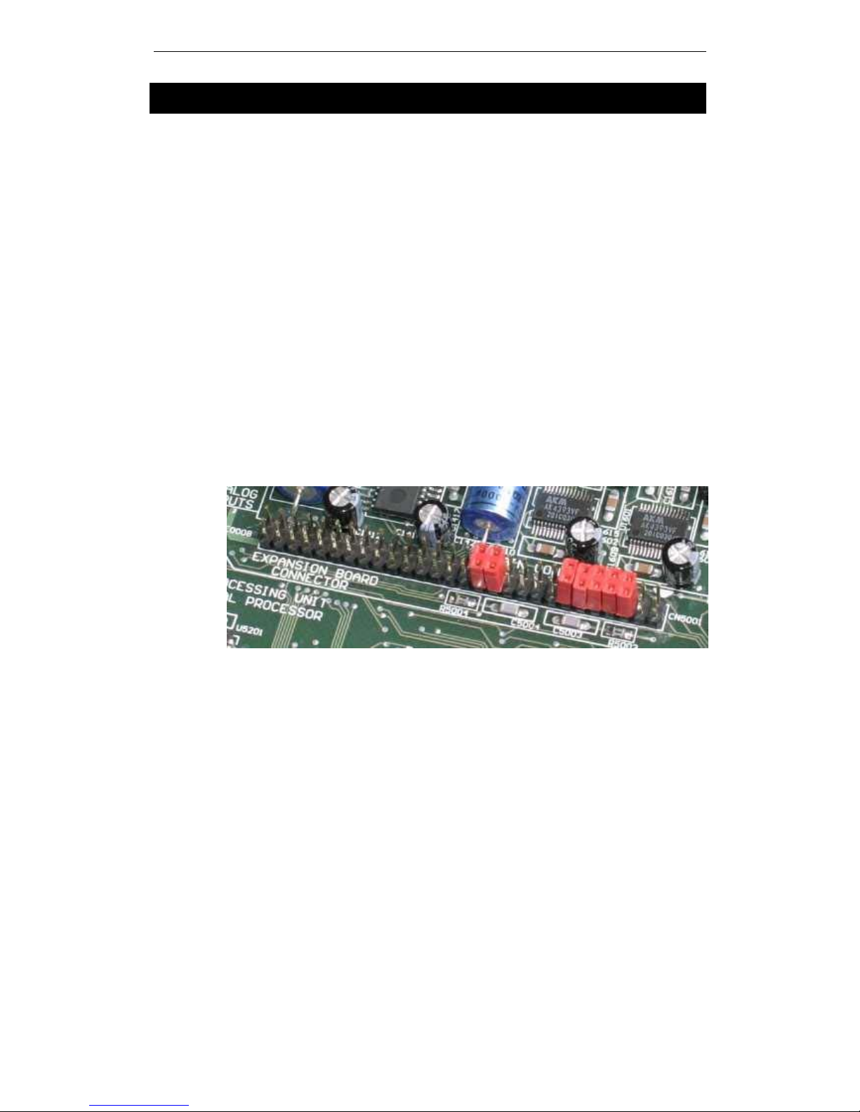
3. Remove the 7 jumpers located on the header CN5001. The positions of the
jumpers are illustrated below, in case you need to remove the board and run
the NX242 without the expander board fitted.
NXTENSION USER MANUAL
DOCUMENT REVISION 150305
PAGE 6

HARDWARE INSTALLATION
4. Insert the NXtension Expander Board in the NX242 by sliding the upper left
corner of the NXtension Expander Board under the corner of the rear panel of
the NX242 back panel until there is enough room to place the upper right
corner inside the NX242. (Supposing that you are facing the front panel of the
NX242)
NXTENSION USER MANUAL
DOCUMENT REVISION 150305
PAGE 7
HARDWARE INSTALLATION
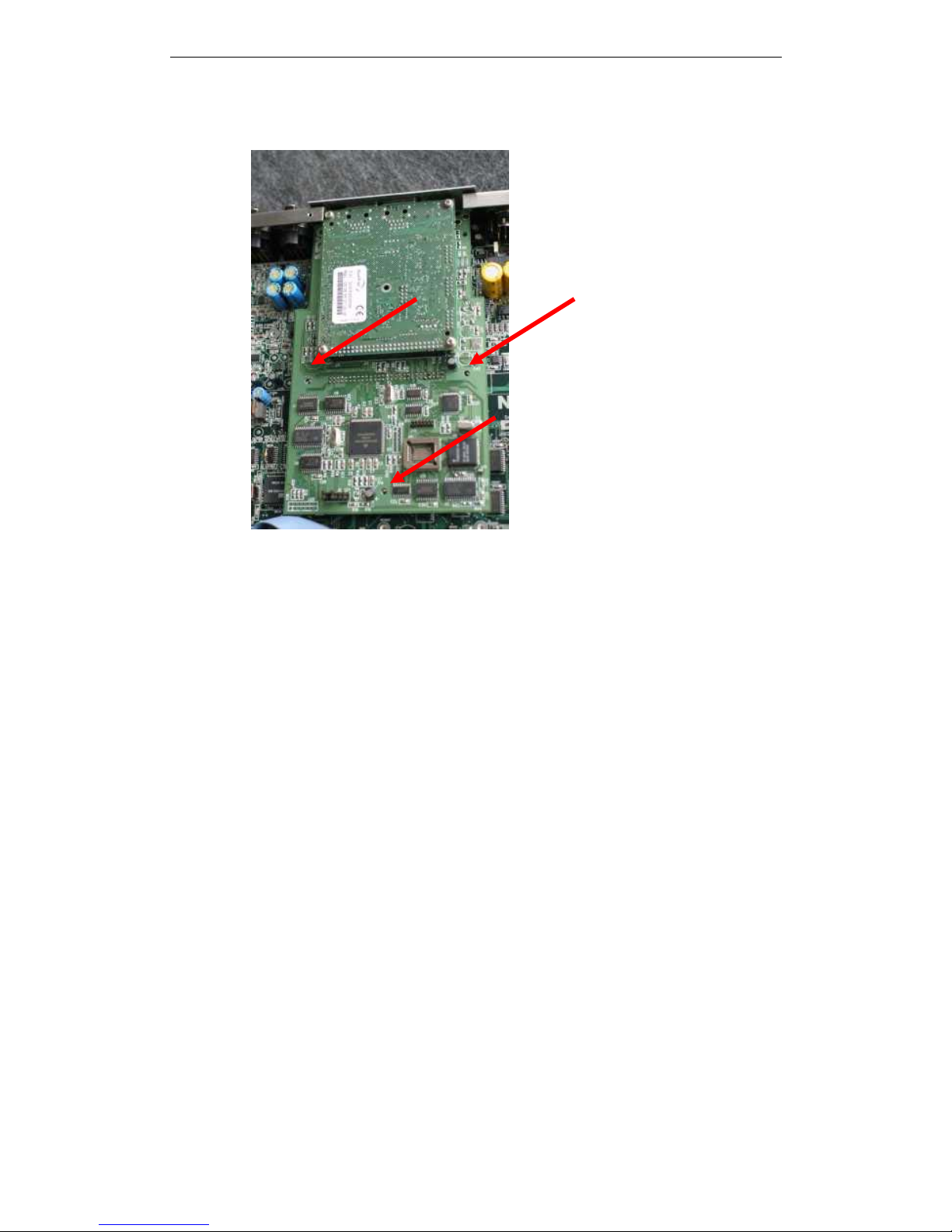
5. Align the NXtension Expander Board on the axis of the spacer ME0004,
ME0006 and ME0008, push gently to insert the board.
6. Screw the NXtension Expander Board into the spacers (3 screws M3x5). Use
the screws provided with the NXtension package.
7. Screw the rear panel of the NXtension Expander Board to the rear panel of
the NX242 (2 self taping screws M3x4). Use the screws provided with the
NXtension package.
8. Replace the top panel. Pay special attention to the screws above the
aluminum heat sink. Only apply a light torque to avoid damaging the thread in
the aluminum.
9. Update the NX242 firmware to allow the NXtension Expander Board to be
activated. Follow the standard updating instructions given in the NX242 user
manual (or documentation provided with the LOAD).
NXTENSION USER MANUAL
DOCUMENT REVISION 150305
PAGE 8
 Loading...