

Nexo NXAMP 4X4 Service Manual

SERVICE MANUAL
Copyright (c) NEXO S.A. All rights reserved. PDF ´09.10
PA
011947
■ CONTENTS
(目次)
PANEL LAYOUT
(パネルレイアウト)
...........................................................3
CIRCUIT BOARD LAYOUT
(ユニットレイアウト)
........................................4
SERVICE PRECAUTIONS
(サービス時の注意)
............................................5
OVERALL ASSEMBLY WIRING
(総組立配線図)
.......................................... 7
DISASSEMBLY PROCEDURES
(分解手順)
...............................................25
LSI PIN DESCRIPTION
(LSI 端子機能表)
...................................................37
IC BLOCK DIAGRAM
(IC ブロック図)
.......................................................38
CIRCUIT BOARDS
(シート基板図)
.............................................................44
TEST PROGRAM .......................................................................................64
テストプログラム
........................................................................................71
INSPECTIONS ...........................................................................................78
検査
.............................................................................................................83
UPDATING THE FIRMWARE .....................................................................88
ファームウェアのアップデート
....................................................................90
PARTS LIST
BLOCK DIAGRAM
IC & DIODE FIGURES
CIRCUIT DIAGRAM
■
WARNING
(注意)
Components having special characteristics are marked and must be replaced with parts having specification equal to those originally
installed.
印の商品は、安全を維持するために重要な部品です。交換する場合は、安全のために必ず指定の部品をご使用ください。
IMPORTANT NOTICE FOR THE UNITED KINGDOM
Connecting the Plug and Cord
WARNING: THIS APPARATUS MUST BE EARTHED
IMPORTANT. The wires in this mains lead are coloured in accordance with the following code:
GREEN-AND-YELLOW: EARTH
BLUE: NEUTRAL
BROWN: LIVE
As the colours of the wires in the mains lead of this apparatus may not correspond with the coloured markings identifying the terminals in your
plug, proceed as follows:
The wire which is coloured GREEN and YELLOW must be connected to the terminal in the plug which is marked by the letter E or by the safety
earth symbol
or colored GREEN or colored GREEN and YELLOW.
The wire which is coloured BLUE must be connected to the terminal which is marked with the letter N or coloured BLACK.
The wire which is coloured BROWN must be connected to the terminal which is marked with the letter L or coloured RED.
WARNING: This product contains chemicals known to the State of California to cause cancer, or birth defects or other reproductive harm.
DO NOT PLACE SOLDER, ELECTRICAL/ELECTRONIC OR PLASTIC COMPONENTS IN YOUR MOUTH FOR ANY REASON WHAT SO
EVER!
Avoid prolonged, unprotected contact between solder and your skin! When soldering, do not inhale solder fumes or expose eyes to solder/flux
vapor!
If you come in contact with solder or components located inside the enclosure of this product, wash your hands before handling food.
NXAMP4x4
2
❶❷❼❸❿ ⓫❻❾❽❺❹
• Front Panel
(フロントパネル)
• Rear Panel
(リアパネル)
■
PANEL LAYOUT
(パネルレイアウト)
❶
Power switch
❷
Amplifier indicators
❸
LCD display
❹
Encoder
❺
Navigation buttons (A & B)
❻
Volume indicators
❶
Mains connectors
❷
Balanced audio inputs with link
❸
Expansion slot
❹
Power outputs
❺
RS-232 Firmware update port
❻
GPIO port
❼
Rear end mounting holes
❶ 電源スイッチ
❷ アンプディスプレイ
❸ LCD ディスプレイ
❹ エンコーダー
❺
ナビゲーションボタン
(A&B)
❶ 電源端子
❷ バランスオーディオ入力(リンク付き)
❸ 拡張スロット
❹ パワー出力
❺ RS-232C ファームウェアアップデート用ポート
❻ GPIO ポート
❼ リアエンド取り付け穴
❼
Mute buttons
❽
Select buttons
❾
Channel indicators
❿
Air intakes
⓫
Screw holes for handles
❻ ボリュームディスプレイ
❼ ミュートボタン
❽ セレクトボタン
❾ チャンネルディスプレイ
❿ 吸気口
⓫ ハンドル用ネジ穴
❸❹ ❻❷❶❺❼
NXAMP4x4
3
■
CIRCUIT BOARD LAYOUT
(ユニットレイアウト)
INANH
RS232-GPI NX-DFLT
NX-DFLT
OPT-AN
PSANHA
PAANHPAANH
(PA unit)
(PA ユニット)
(PA unit)
(PA ユニット)
Rear Panel (リアパネル)
PSANHA
RS232-GPI
(PA unit)
(PA ユニット)
PAANH
(PA unit)
(PA ユニット)
PAANH
Front Panel (フロントパネル)
PN-AN
PSANHBOUTANH
OPT-AN
INANH
CONTROL
NXAMP4x4
4
■
SERVICE PRECAUTIONS
(サービス時の注意)
Safety measures
• Some component parts on the PSANH circuit board
maintain a high voltage even when the power is switched
off. For this reason to avoid an electrical shock, do not
touch the upper metallic part of the following capacitors
until the remaining voltage has discharged.
安全対策
・ PSANH シートの部品の一部には電源 OFF 状態でも高
電圧が残ります。感電防止のため、残った電圧を放電
するまで下記のコンデンサの上部の金属部分に触らな
いでください。
[放電方法]
修理作業を始める前に、放電抵抗(220 Ω、10W)を
下図に示す放電用の端子間に接続します。(7 箇所)
放電に必要な時間は約 10 秒です。放電完了確認のため、
端子間電圧がほぼ 0(ゼロ)V であることをテスターで
チェックします。
注意:
C205 の放電完了まで IC201 とそれを固定しているヒー
トシンクには触らないでください。
[Discharging Method]
Before starting the service work, connect discharging
resistors (220 Ω 10W) to the terminals indicated in the
figure below to discharge electricity. (7 points)
The required discharging time is about 10 seconds.
Check that the DC voltage between the terminals
measures close to 0 (zero) volts using a multi-meter to
make sure that the discharge is completed.
Note:
Do not touch the IC201 and its heat sink before
discharging the C205.
PSANH circuit board
Capacitors /
コンデンサ
Discharging point /
放電箇所
C316, C317, C322, C323
①
D305: + pin <=> D305: - pin
C318, C319, C324, C325
②
D306: + pin <=> D306: - pin
C344, C354
③
CN305 <=> CN316
C345, C355
④
CN307 <=> CN316
C347, C356
⑤
CN308 <=> CN309
C348, C357
⑥
CN310 <=> CN309
C205
⑦
R213: lead <=> C201
C323 C322
REAR
FRONT
C317 C316
C324 C318
C325
C205
C201
R213
C344 C354
C345 C355
C357
C356
C348
C347
C319
D305
220 ohms/
10W
220 ohms/
10W
220 ohms/10W
220 ohms/10W
220 ohms/10W
220 ohms/10W
220 ohms/10W
D306
1
3
4
2
CN316
CN307 CN305 CN308
CN310
CN309
6
7
5
NXAMP4x4
5
XX
To FAN
To FAN
Primary
ANH
ANH
ANH
ANH
PSANHA
PSANHB
ANH
ANH
ANH
Secondary
ANH
ANH
ANH
ANH
ANH
220 ohms/10W
220 ohms/10W
220 ohms/10W
C316
D305
C322
C354C344
C355C345
C356C347
C357C348
C317 C323
3
4
6
1
220 ohms/10W
C318
D306
C324
C319 C325
2
C305
C307
C316
220 ohms/10W
220 ohms/10W
5
PSANH circuit diagram
1
2
PSANHA only
PSANHB only
PSANHA only
PSANHA only
C205
C201
220 ohms/10W
7
NXAMP4x4
6
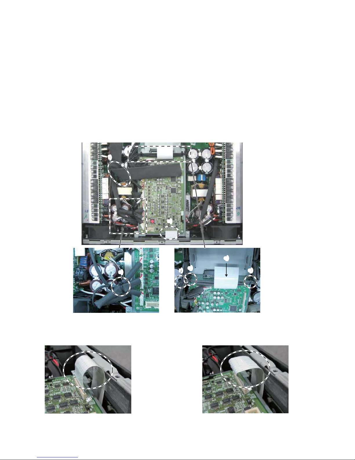
This product has various cables (wires and connector
assemblies) inside. To prevent touching component to
the cables and/or connection mistake, perform the cable
connection and fixing cables according to the following
instructions referring the wiring diagram, P3 of the circuit
diagram.
Notice: Since the following pictures are taken of the
preproduction product, they may differ from the
commodity products in detail. However, the wiring
and so on is not so differ between them. So, refer
only to wiring and so on.
1. Wiring of the PN-AN circuit board
1) Process the PN FFC assembly (WR37010). (Fig. 1, 2)
2) Connect the PN FFC assembly (WR37010) to the PNAN circuit board. (Fig. 3)
3) Install the PN-AN circuit board to the front panel.
本製品内部には色々な種類のケーブル(線材、束線)があり
ます。ケーブルの部品への接触やケーブルの接続ミスを防止
するために、回路図 3 ページのシート配線図を参照の上で下
記の指示にしたがってケーブルの接続と固定を行ってくださ
い。
注意: 掲載した写真は量産試作品を撮影したものですので
生産品とは細かい部分で異なりますが、配線周辺に
ついて違いはありません。配線作業用に限定して参
考にしてください。
1. PN-AN シートの配線
1) PNFFCAss'y(WR37010)を加工します。(図 1、2)
2) PNFFCAss'y(WR37010)を PN-AN シートへ接続し
ます。(図3)
3) PN-AN シートをフロントパネルへ取り付けます。
Fig. 1
(図 1)
Fig. 3
(図 3)
Fig. 2
(図 2)
■
OVERALL ASSEMBLY WIRING
(総組立配線図)
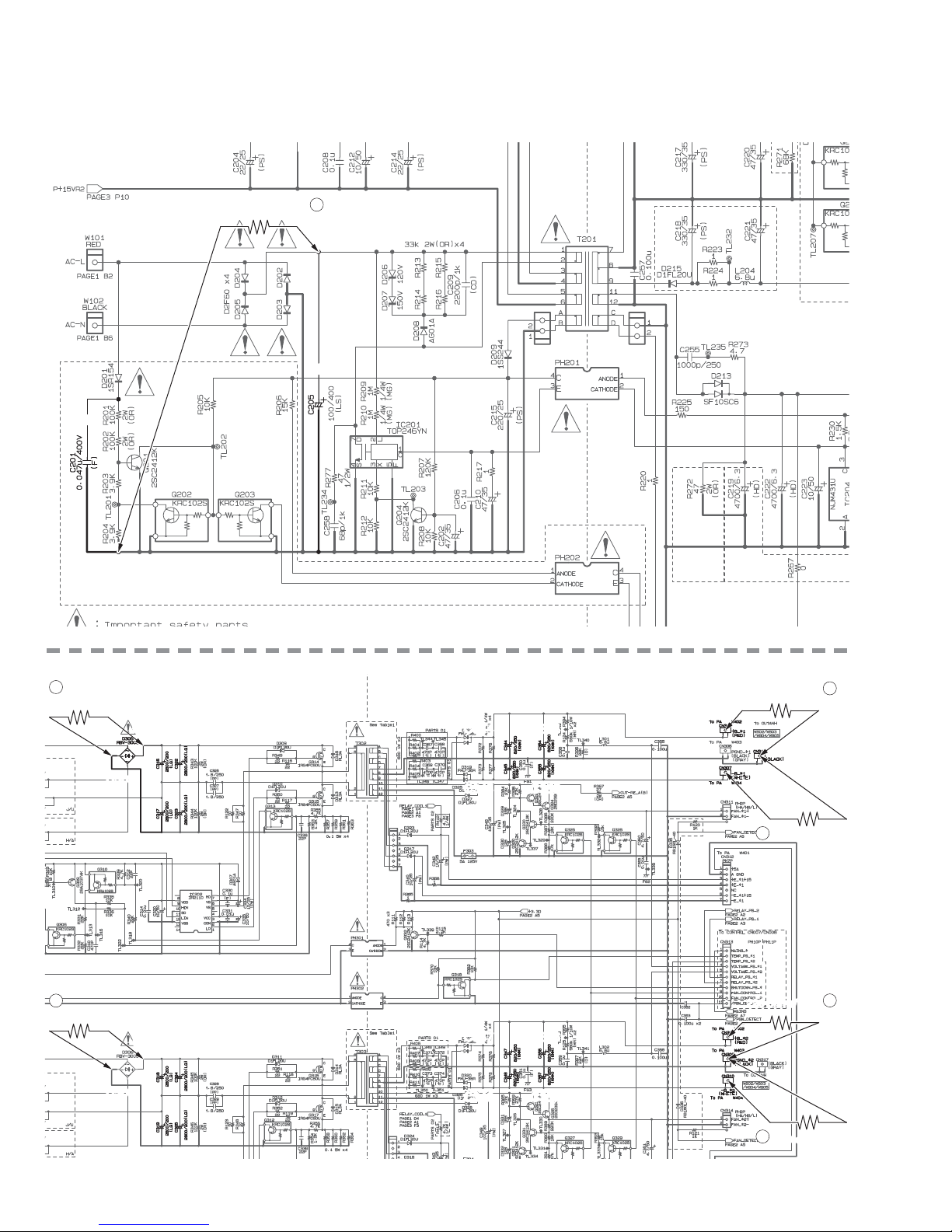
115 ±1 mm
25 ±1 mm
90˚ 90˚
[635]
Fix the bent part with adhesive tape [635].
(Attach it through the center of FFC.)
(折り曲げた部分をフィラメントテープ[635]で固定します。
(FFC の中心を通るように貼ります。))
* For details of wiring in the enclosure, refer to step “13.
Method of Fixing PN FFC Assembly”.
※ 筐体内部での配線についての詳細は「13. PN FFC
Ass'y の固定方法」を参照してください。
NXAMP4x4
7
2. Wiring of the power switch
1) Install the power switch to the front panel with its
terminals set downward. (Fig. 4, 5)
2) Confirm that the power switch is set to the off position as
shown in the figure. (Fig. 6)
3) Twist the wires of the power switch assembly more than
three times.
4) Connect the power switch connector assembly to the
connector (CN103) of the PSANHB circuit board. (Fig. 7)
2. 電源スイッチの配線
1) 端子の位置を下側にセットして、電源スイッチをフロ
ントパネルへ取り付けます。(図 4、5)
2) 電源スイッチが図のように OFF ポジションにセットさ
れていることを確認します。(図 6)
3) 電源スイッチの線材を 3 回以上捻ります。
4) 電源スイッチの線材を PSANHB シートのコネクター
(CN103)へ接続します。(図 7)
Fig. 4
(図 4)
Fig. 6
(図 6)
Fig. 5
(図 5)
Fig. 7
(図 7)
Check (確認すること)
NXAMP4x4
8
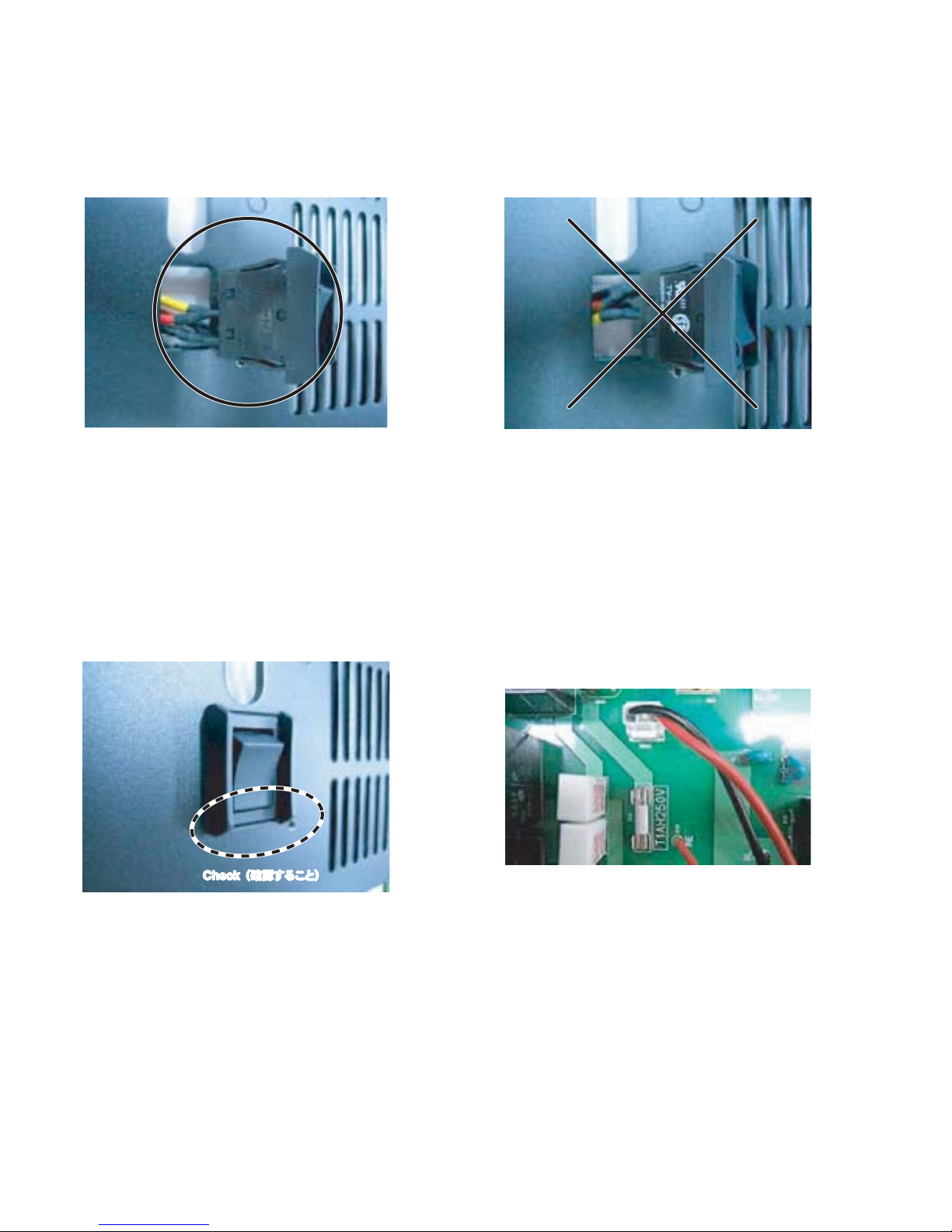
3. ファンの配線
ファンの線材を各コネクターへ接続します。(図8)
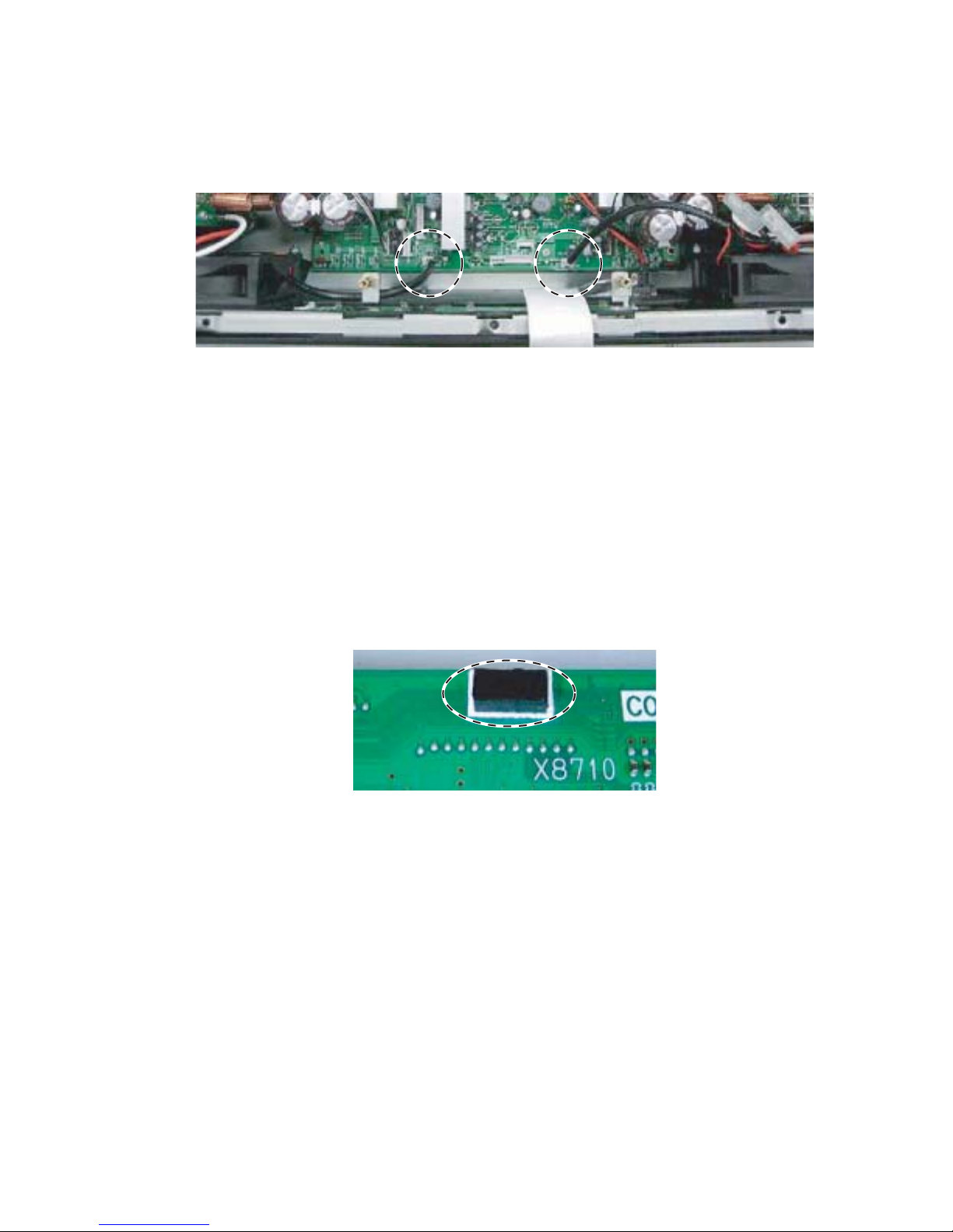
4. サポートクッションの取り付け
CONTROL シートパターン面の所定の位置にサポート
クッション(WN15950)を取り付けます。(図 9)
注意: サポートクッションを取り付ける前に、取り付
け面の油、埃などはきれいに取り除いてくださ
い。
Fig. 8
(図 8)
Fig. 9
(図 9)
3. Wiring of the FAN
Connect the wire of the FAN to each connector. (Fig. 8)
4. Attaching of the support cushion
Attach the support cushion (WN15950) at the specified
area on the pattern side of the CONTROL circuit board.
(Fig. 9)
Note: Be sure to remove the oil and the dust, etc. on
the attaching surface before attaching the support
cushion.
NXAMP4x4
9
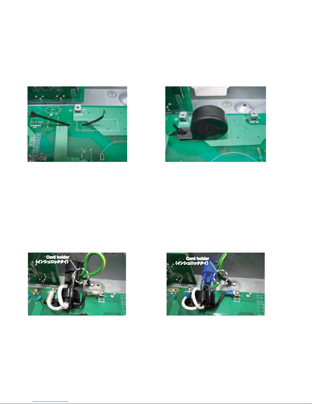
5. Wiring of the AC-INLET
a) Set a cord holder before installing the PSANHB circuit
board to the enclosure. (Fig. 10)
b) Set a ferrite-core at the specified area on the PSANHB
circuit board, and fasten the ferrite-core with a cord
holder. (Fig. 11)
c) Pass the live and neutral wires of the AC-INLET through
the ferrite core’s hole twice and wind them to the ferrite
core.
Screw each screw terminal to the specified terminal.
(Fig. 12, 13)
Fasten the GND wire with a cord holder. (Fig. 12, 13)
Screwing torque: GND LINE 1.8N • m /
L, N LINE 0.78 • m
c) AC インレットの L、N の線をフェライトコアの穴に 2
回通して、フェライトコアに巻きつけます。
各端子を図のように固定します。(図 12、13)
GND 線をインシュロックタイで図のように固定しま
す。(図 12、13)
ネジ締め付けトルク: GNDLINE1.8 N・m /
L、NLINE0.78・m
5. AC インレットの配線
a) PSANHBシートを取り付ける前に、インシュロックタ
イをセットします。(図 10)
b) PSANHBシートの所定の位置にフェライトコアをセッ
トし、インシュロックタイで固定します。(図 11)
Fig. 10
(図 10)
Fig. 12
(図 12)
Fig. 11
(図 11)
Fig. 13
(図 13)
Cord holder
(イン シュロックタイ)
Cord holder
(イン シュロックタイ)
U/J destination
(U / J 仕向)
CHN destination
(CHN 仕向)
NXAMP4x4
10
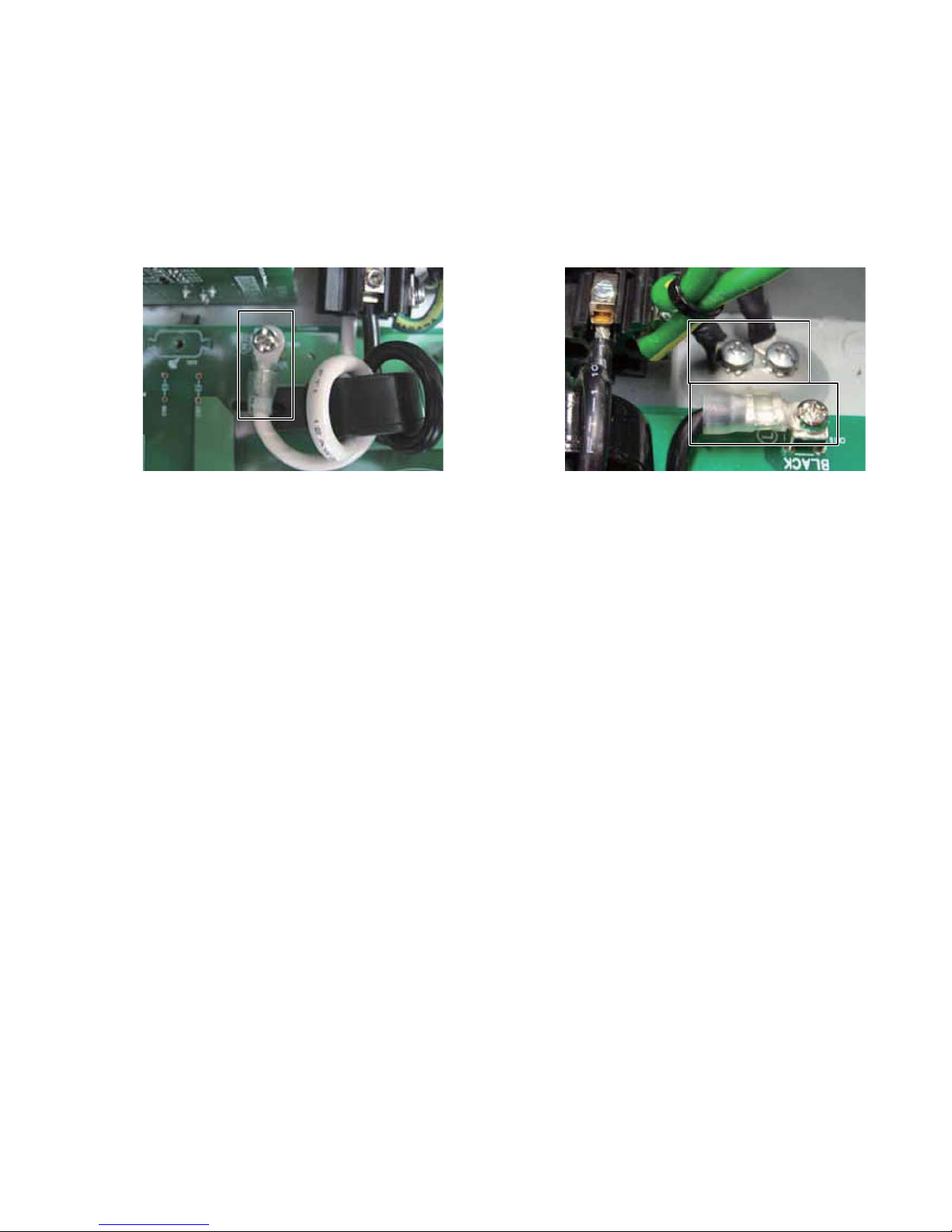
d, e) Fix the wires to the terminal with the screws, and refer to
the fig. 14 and fig. 15 for the direction of each terminal.
Screw the GND wire’s screw terminal of the upper ACINLET as shown in the figure, and don’t fasten it with a
cord holder. (Fig. 14, 15)
d
、
e)端子をネジで固定します。このとき端子の向きは図に
従ってください。
上側の AC インレットの GND 線を図のようにネジで固
定します。ただし、このときインシュロックタイで固
定しないでください。(図 14、15)
Fig. 14
(図 14)
Fig. 15
(図 15)
NXAMP4x4
11
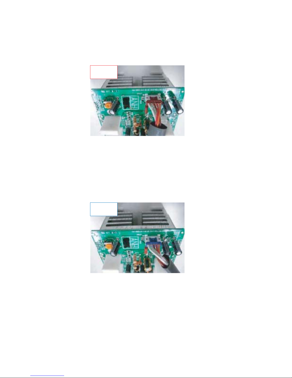
6. Wiring of the PA unit
Connect the wire to the CN401. (Fig. 18, 19, 20 and 21)
NOTE: The wire to be connected is WK02080.
Install this PA unit on the upper left side of
enclosure.
Hereafter, this unit is called PA unit of CH1.
注意: 線材(WK02080)を接続します。
この PA ユニットを筐体の上左側へ取り付け
ます。
これ以後、このユニットを CH1 の PA ユニッ
トと呼びます。
6. PA ユニットの配線
下図のように CN401 へ線材を接続します。(図 18、
19、20、21)
CN401
RED (赤)
Fig. 18
(図 18)
Fig. 19
(図 19)
NOTE: The wire to be connected is WK17090.
Install this PA unit on the upper right side of
enclosure.
Hereafter, this unit is called PA unit of CH2.
注意: 線材(WK17090)を接続します。
この PA ユニットを筐体の上右側へ取り付け
ます。
これ以後、このユニットを CH2 の PA ユニッ
トと呼びます。
CN401
BLUE (青)
NXAMP4x4
12
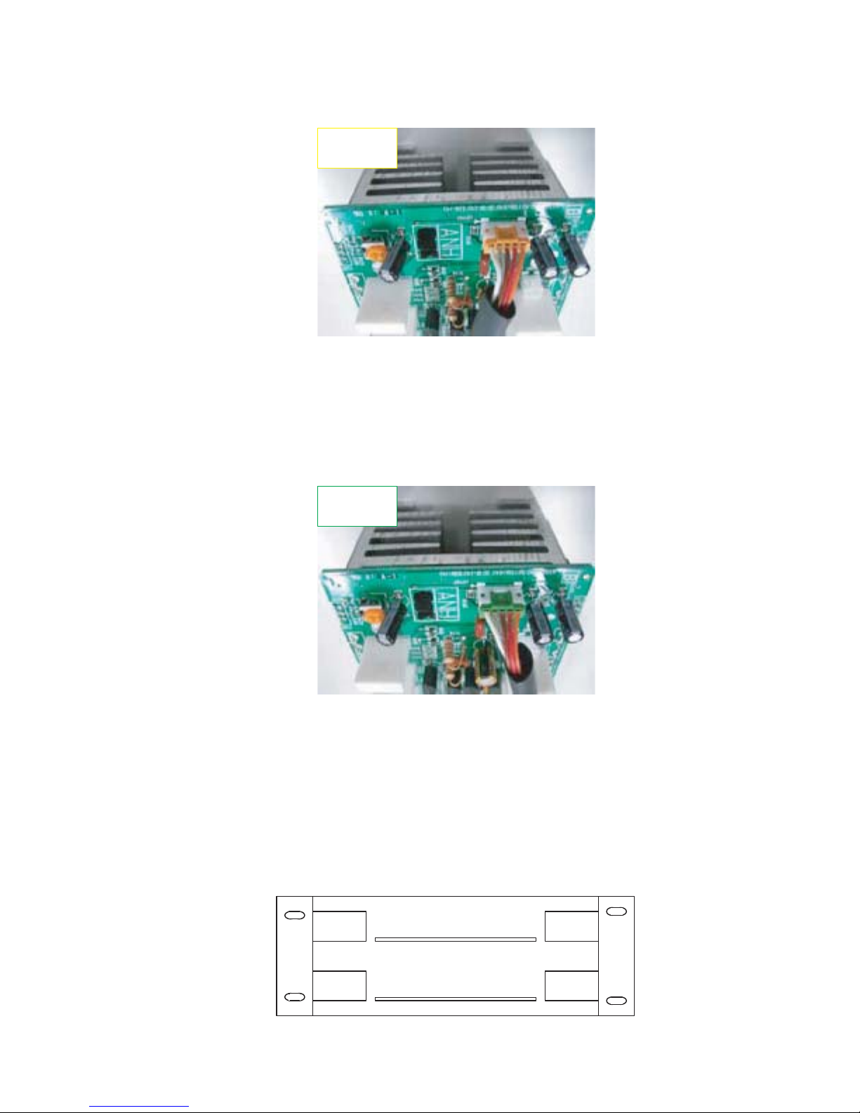
Fig. 20
(図 20)
Fig. 21
(図 21)
NOTE: The wire to be connected is WK17110.
Install this PA unit on the lower right side of
enclosure.
Hereafter, this unit is called PA-UNIT of CH4.
注意: 線材(WK17110)を接続します。
この PA ユニットを筐体の下右側へ取り付け
ます。
これ以後、このユニットを CH4 の PA ユニッ
トと呼びます。
NOTE: The wire to be connected is WK17100.
Install this PA unit on the lower left side of
enclosure.
Hereafter, this unit is called PA unit of CH3.
注意: 線材(WK17100)を接続します。
この PA ユニットを筐体の下左側へ取り付け
ます。
これ以後、このユニットを CH3 の PA ユニッ
トと呼びます。
CN401
YELLOW (黄)
CN401
GREEN (緑)
* The following figure describes a layout drawing of
the PA units seen from the front panel. (Fig. 22)
※ 次の図は、フロントパネル側から見た PA ユニッ
トのレイアウト図です。(図 22)
CH1
RED
(赤)
CH3
YELLOW
(黄)
CH2
BLUE
(青)
CH4
GREEN
(緑)
PSANHA
PSANHB
Fig. 22
(図 22)
NXAMP4x4
13

7. Wiring and fastening
Connect the following wires at first.
CN313: WK68740
CN203: WK66350
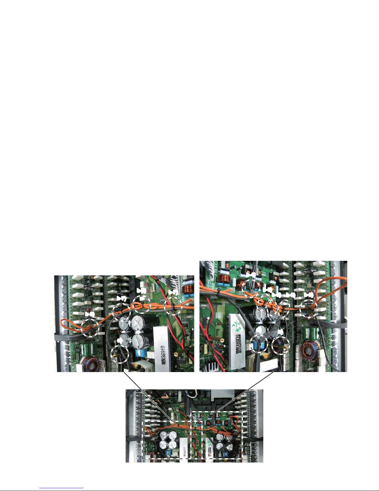
a) Fasten these wires (WK17900, WK17910 and WK94690)
with a cord holder to the hexagonal spacer. (Fig. 23)
Note: Do not fasten the wires (brown and yellow) of
WK94690 because they must be connected to
the PSANHA (upper PSANHA) circuit board
later.
b) Connect the wire (WN52520) of each PA unit (CH1–CH4)
to CH1–CH4 connectors of the OUTANH circuit board
referring the component location printed on the board.
(Fig. 23)
Way of fastening wire
b-1) Fold the wires of the lower PA unit at the center of
them.
b-2) Pull the wires of the upper PA unit toward the PA
unit. (Do not fold these wires.)
7. 配線と固定
初めに下記の線材を接続します。
CN313:WK68740
CN203:WK66350
a) 線材(WK17900、WK17910、WK94690)をインシュ
ロックタイで六角スペーサーへ固定します。(図 23)
注意: 束線(WK94690)の線材(茶色、黄色)は、
後で上側にある PSANHA シートへ接続するの
で、ここでは固定しません。
b) 各 PA ユ ニ ッ ト(CH1 〜 CH4)の線材(WN52520)
を、OUTANH シートに印刷された表示にしたがって
OUTANH シートのファストン端子へ接続します。
(図 23)
線材の固定方法
b-1)下側の PA ユニットの線材を図のように中央で折
りたたみます。
b-2)上側の PA ユニットの線材を PA ユニット側に引っ
張ります。
(この線材は折りたたまないでください。)
Fig. 23
(図 23)
a)
NXAMP4x4
14
b-8)
b-7)
b-3)
b-7)
b-4)
b-5)
b-6)
b-5)
b-3)
c)
d)
c)
b-3) Then
fasten these wires with a cord holder as
shown in the figure.
b-4) Fasten these wires (WM04880 x 2, WK16820 x 2)
with a cord holder.
b-5) Fasten these wires (WN52520 x 2, WK16820 x 2)
with a cord holder (2 places).
b-6) Fasten these wires (WN52520, WK16820) with a
cord holder (1 place).
* Bend wire (WN52520) once.
b-7) Fasten these wires (WN52520 x 2, WM04880 x 2)
with a cord holder (2 places).
b-8) Fasten these wires (WN52520, WM04880) by wire
harness Tie (1 place).
* Bend wire (WN52520) once.
c) Connect the wire (WM04880) to connector (CN306) of
the PSANHA circuit board. Connect the wire (WK16820)
to the connector (CN317) of the PSANHB circuit board.
Fasten these wires (WM04880, WK16820) with a cord
holder to the hexagonal spacer as shown in the figure.
(Pass the wires to the PA unit side of a hexagonal
spacer)
d) Connect the wire (WK14210) of the PA unit (CH4) to the
connector (CN315) of the PSANHB circuit board. (Draw
the Black tube to the PA unit side.)
Pull the wire (WK14210) from PA unit to the direction of
T301 and fasten these wires (WK14200, WK14210) with
a cord holder. Before fastening, pull the wire (WK14200)
toward the front panel side in advance.
b-3)その後、これらの線材を図のようにインシュロッ
クタイで固定します。
b-4)線材(WM04880x2、WK16820x2)をインシュ
ロックタイで固定します。
b-5)線材(WN52520x2、WK16820x2)をインシュ
ロックタイで固定します。(2 箇所)
b-6)線材(WN52520、WK16820)をインシュロック
タイで固定します。(1 箇所)
※ WN52520 は一度折り返します。
b-7)線材(WN52520x2、WM04880x2)をインシュ
ロックタイで固定します。(2 箇所)
b-8)線材(WN52520、WM04880)をインシュロック
タイで固定します。(1 箇所)
※ WN52520 は一度折り返します。
c) 線材(WM04880)を PSANHA シートのコネクター
(CN306)へ、線材(WK16820)を PSANHB シート
のコネクター(CN317)へ接続します。
線材(WM04880、WK16820)を図のようにインシュロッ
クタイで六角スペーサーへ固定します。
(線材を六角スペーサーの PA ユニット側を通します)
d) PA ユニット(CH4)の線材(WK14210)を PSANHB シー
トの CN315 へ接続します。(スミチューブを PA ユニッ
ト側に寄せます。)
線材(WK14210)を PA ユニットから T301 の方向に
引っ張り、線材(WK14200、WK14210)をインシュロッ
クタイで固定します。このとき線材(WK14200)をフ
ロント側へ引っ張っておきます。
Fig. 24
(図 24)
NXAMP4x4
15
e)
f)
f)
f)
g)
g)
g)
g)
h-1)
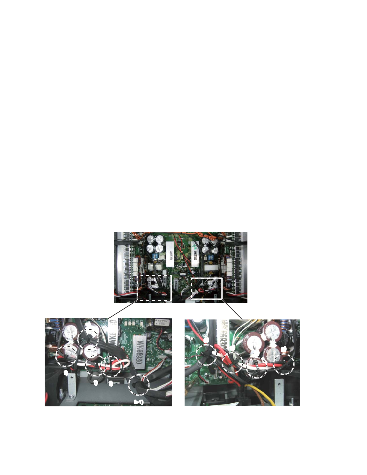
e) Connect the wire (WK14210) of the PA unit (CH3) to the
connector (CN312) of the PSANHB circuit board. (Draw
the black tube to the PA unit side.)
Fasten the wire (WK14210) and the wire of the FAN with
a cord holder. (Fig. 22)
f) Twist the wires (white, red, black) of the PA unit more
than two times, and connect them to the terminals
according to the wire color displayed on the PSAN circuit
board. Fasten these wires (white, red, black) and wire
(WM04880) with a cord holder. (2 places)
Then bend the wires (white, red, black), and fasten them
with a cord holder. (Fig. 22)
g) Connect the wires (white, red, black) of PA unit to the
terminals in the same manner as step f).
Fasten these wires (white, red, black) and wire
(WK16820) with a cord holder (2 places). And then,
bend these wires (white, red, black) and fasten them
with a cord holder.
Fasten the wires (WK14210, WK14200) and the wire of
FAN with a cord holder.
h)
h-1) Fasten the wires (WK68740, WK14200, WK66350)
with a cord holder.
e) PA ユニット(CH3)の線材(WK14210)を PSANHB シー
トの CN312 へ接続します。(スミチューブを PA ユニッ
ト側に寄せます。)
線材(WK14210)と FAN の線材を図のようにインシュ
ロックタイで固定します。
f) PA ユニットの線材(白、赤、黒)を 2 回以上捻った後、
PSAN シートに表示された線材の色にしたがって各線
材をファストン端子へ接続します。そのとき、それら
の線材(白、赤、黒)と線材(WM04880)をインシュ
ロックタイで固定します。(2 箇所)
またそれら(白、赤、黒)の線材を折り曲げた後インシュ
ロックタイで固定します。
g) f)と同じ方法で、PA ユニットの線材(白、赤、黒)を
端子へ接続します。
それら(白、赤、黒)の線材を、線材(WK16820)と
一緒にインシュロックタイで固定します。(2 箇所)
またそれら(白、赤、黒)の線材を折り曲げた後、インシュ
ロックタイで固定します。
線材(WK14210、WK14200)と FAN の線材をまとめ
てインシュロックタイで固定します。
h)
h-1)線材(WK68740、WK14200、WK66350)をイン
シュロックタイで固定します。
Fig. 25
(図 25)
NXAMP4x4
16
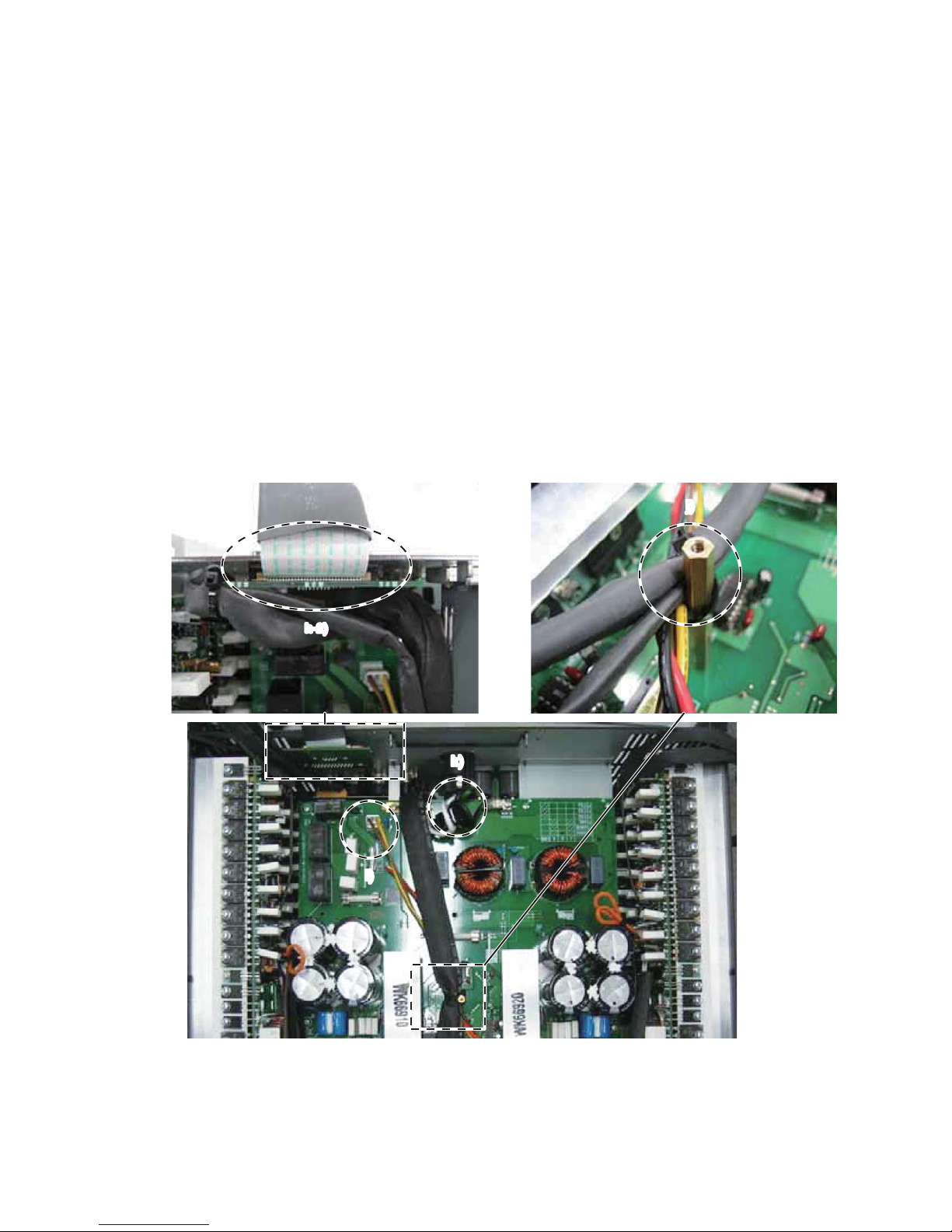
At the stage as shown in Fig. 26, connect the
following wires.
CN313: WK68760
CN201: WK68770
CN202: WK14200 from OUTANH board
CN203: WK66350 from PSANHB board
h-2) After connecting the wire (WM15830) to it, install
the RS232-GPI circuit board to the enclosure.
i) Twist the wires (yellow, brown) of the power switch
assembly more than three times, and connect it to the
connector (CN103) of the PSANHA circuit board.
j) Fasten these wires (WK17900, WK17910, WK94690 and
WK02090) with a cord holder to the hexagonal spacer.
k) Connect the wire of the AC-INLET according to the step
“5. Wiring of the AC-INLET”.
Note: Do not fasten the GND wire with a cord holder.
図 26 の段階で下記の線材を接続しておきます。
CN313:WK68760
CN201:WK68770
CN202:WK14200OUTANHシートから
CN203:WK66350PSANHBシートから
h-2)RS232-GPI シートに線材(WM15830)を接続し
た後、RS232-GPI シートを筐体へ取り付けます。
i) 電源 SW の線材(黄色、茶色)を 3 回以上捻った後、
PSANHA シートのコネクター(CN103)へ接続します。
j) 線材(WK17900、WK17910、WK94690、WK02090)
をインシュロックタイで六角スペーサーへ固定します。
k) 「5. AC インレットの配線」にしたがって AC インレッ
トの線材を接続します。
注意: GND 線材はインシュロックタイで固定しない
でください。
Fig. 26
(図 26)
h-2)
j)
k)
i)
NXAMP4x4
17

l)
m-1)
m-2)
m-3)
m-1)
m-2)
m-3)
l)
n)
l) Connect the wire (WK14210) of PA unit (CH1) to the
connect
or (CN312) of the PSANHA circuit board.
(Draw a black tube to the PA unit side.)
Connect the wire (WK14210) of PA unit (CH2) to the
connector (CN315) of the PSANHA circuit board.
(Draw a black tube to the PA unit side.)
Fasten the wire (WK14210) and the wire of FAN with a
cord holder as shown in the figure. (Fig. 24)
m) Twist the wires (white, red, black) of the PA unit more
than two times, and connect them to the FASTON
terminals according to the wire color displayed on the
PSANHA circuit board.
m-1, 2) Fasten these wires (white, red, black) together
with wires (WM04880, WK16820) with a cord
holder as shown in the figure.
m-3) Bend these wires (white, red, black) and fasten
them with a cord holder as shown in the figure.
n) Fasten the wire (WN52520) with a cord holder.
(Fig. 25, 26)
Note: When connecting the connector assembly to
the CONTROL circuit board、 confirm that the
connector housing pin number of the connector
assembly is the same as the connector pin
number of the circuit board.
l) PA ユニット(CH1)の線材(WK14210)を PSANHA シー
トのコネクター(CN312)へ接続します。(スミチュー
ブを PA-UNIT 側に寄せます。)
PA ユニット(CH2)の線材(WK14210)を PSANHA シー
トのコネクター(CN315)へ接続します。(スミチュー
ブを PA-UNIT 側に寄せます。)
線材(WK14210)と FAN の線材をインシュロックタ
イで図のように固定します。
m) PA ユニットの線材(白、赤、黒)を 2 回以上捻った
後、PSANHA シートに表示された線材の色にしたがっ
てファストン端子に接続します。
m-1、2)これらの線材(白、赤、黒)を線材(WM04880)、
(WK16820)と一緒にインシュロックタイで
固定します。
m-3) それら(白、赤、黒)の線材を折り曲げた後、
インシュロックタイで固定します。
n) 線材(WN52520)を図のようにインシュロックタイで
固定します。
注意: CONTROL シートに束線を接続するとき、
線材側のコネクターハウジングのピン数が
CONTROL シート側のコネクターのピン数と
同じであることを確認してください。
Fig. 27
(図 27)
NXAMP4x4
18
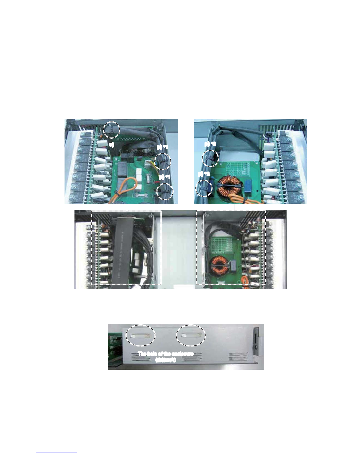
o) Fasten the wires (WK02080, WK17100) with a cord
holder to the hole of the RS232-GPI circuit board.
(Fig. 28)
p) 1) Fasten the wires (WK02080, WK17100 and
WK02070) with a cord holder to the hole of the
enclosure. (Fig. 28 *1, 29)
2) Fasten the wires (WK17090, WK17110) with a cord
holder to the hole of the enclosure. (Fig. 28 *2, 29)
o) 線材(WK02080、WK17100)をインシュロックタイ
で RS232-GPI シートの穴へ固定します。(図 28)
p)1) 線材(WK02080、WK17100、WK02070)をイン
シュロックタイで筐体の穴へ固定します。
(図 28*1、29)
2) 線材(WK17090、WK17110)をインシュロック
タイで筐体の穴へ固定します。(図 28*2、29)
Fig. 28
(図 28)
Fig. 29
(図 29)
o)
p)
*1
p)
*2
p)
*2
p)
*1
The hole of the enclosure
(筐体の穴)
NXAMP4x4
19
q) Fasten the wires (WK17090 and WK17110) with a cord
holder at the hole of the OPT-AN board. Then connect
the flat cable (WK02120). (Fig. 30)
r) Fasten the wires (WK02080, WK17090, WK17100,
WK17110 and WK02070) with a cord holder at the close
area to the OPT-AN circuit board. (Fig. 30)
s) Fasten the wires (WK68740, WK68760 and WK68770)
with a cord holder. (Fig. 30)
t) Bend the flat cable as shown in the figure. (Fig. 30)
u) Bend the flat cable to prevent it from touching the top
cover. (Fig. 31, 32)
q) 線材(WK17090、WK17110)をインシュロックタイ
で OPT-AN シートの穴へ固定します。その後、フラッ
トケーブル(WK02120)を接続します。(図 30)
r) OPT-AN シートの横で線材(WK02080、WK17090、
WK17100、WK17110、WK02070)をインシュロック
タイで固定します。(図 30)
s) 線材(WK68740、WK68760、WK68770)を図のよう
にインシュロックタイで固定します。(図 30)
t) フラットケーブルを図のように折り曲げます。(図 30)
u) トップカバーとの接触を避けるためにフラットケーブ
ルを折り曲げます。(図 31、32)
Fig. 30
(図 30)
Fig. 31
(図 31)
Fig. 32
(図 32)
t)
u)
s)
r)
q)
q)
q)
NXAMP4x4
20

CN012
RED
(赤)
CN013
BLUE
(青)
CN014
YELLOW
(黄)
CN015
GREEN
(緑)
8. Color of the connectors connected to the
connector CN012–CN015
Connect the connector assembly from the PA unit to the
CONTROL circuit board as shown in the figure below.
(Fig. 33)
9. Change of the destination
Set the knob position of the switch SW001 on the
CONTROL circuit board as shown in the figure below.
(Fig. 34, 35)
8. CN012 − CN015 へ接続するコネクターの色
PAユニットからの束線を下図のようにCONTROLシー
トへ接続します。(図 33)
9. 仕向け先の切り替え
CONTROL シートのスイッチ(SW001)を下図のよう
に切り替えます。(図 34、35)
Fig. 33
(図 33)
Fig. 34
(図 34)
Fig. 35
(図 35)
Switch knob
(切替ノブ)
Switch knob
(切替ノブ)
U/J destination
(U / J 仕向)
CHN destination
(CHN 仕向)
NXAMP4x4
21
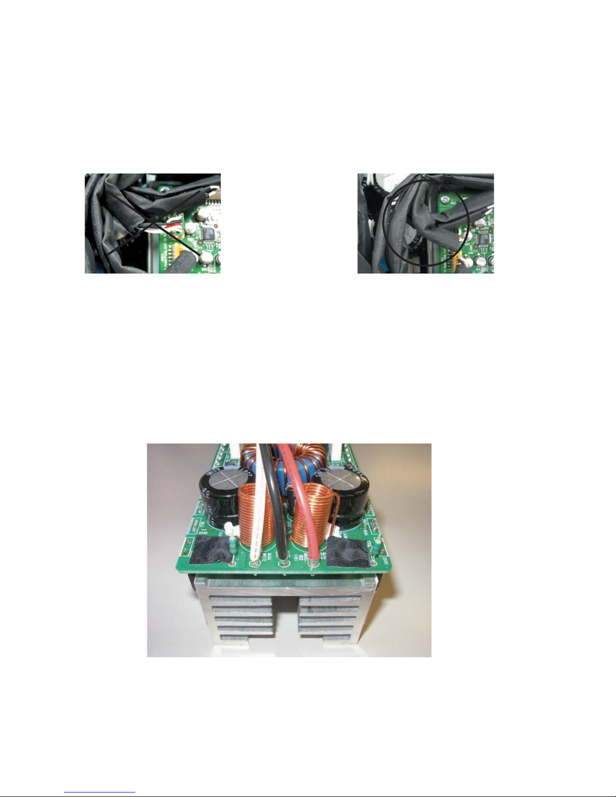
10. Insulation distance between wire (WK17110)
and primary side capacitor
Perform wiring of the connector assembly (WK17110)
with care so that its uncovered portion with the SUMI
tube does not touch the capacitor (C316) on primary
side of the PSANHA circuit board. (Fig. 36, 37)
11. Adhesive cloth tape
Cover the two screws near R587 and R588 in each PA
unit [190, 220, 250 and 280] with adhesive cloth tape
[185, 215, 245 and 275] as shown in the figure below.
(Fig. 38)
10.束線 WK17110 と 1 次側ケミコンの絶縁距離
束線(WK17110)を配線するとき、スミチューブに覆
われていない部分が PSANHA シートの 1 次側にあるコ
ンデンサ(C316)に接触しないように注意してくださ
い。(図 36、37)
11.アセテートクロス粘着テープ
各 PA ユ ニ ッ ト[190、220、250、280] の R587、
R588 の直近にある 2 つのネジを下図のようにアセテー
トクロステープ[185、215、245、275]で覆います。
(図 38)
Fig. 36
(図 36)
Fig. 38
(図 38)
Fig. 37
(図 37)
NXAMP4x4
22
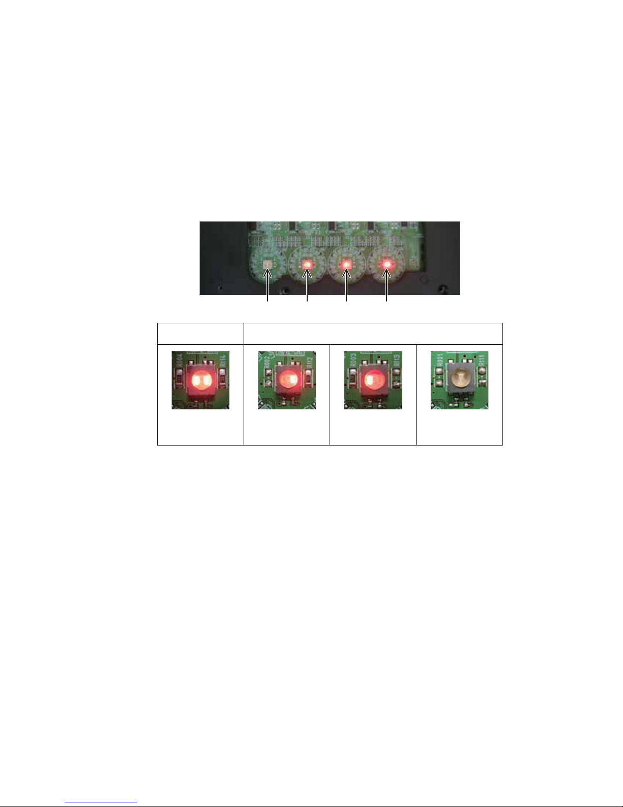
12. Confirmation of Switch LED lighting
With the front panel 2 uninstalled, confirm that the LEDs
of switches (SW003–SW006) light. (Fig. 39)
Procedure
1. Press the power switch of this unit to turn on the
power.
2. Press the switches (SW003–SW006) on the PN-AN
circuit board, and confirm that both LEDs of each
switch light.
12.スイッチ LED 点灯確認
フロントパネル2を取り外した状態で、スイッチ
(SW003 〜 SW006)の LED が点灯することを確認し
ます。(図 39)
手順
1. 本機の電源スイッチを ON にします。
2. PN-AN シートのスイッチ(SW003 〜 SW006)
を押し、各スイッチの両方の LED が点灯すること
を確認します。
Fig. 39
(図 39)
OK NG
Lighting of both
(両方とも点灯)
Left is turned off
(左が消灯)
Turning off of both
(両方とも消灯)
Right is turned off
(右が消灯)
SW003 SW004 SW005 SW006
NXAMP4x4
23

It is based on this position.
(この位置を基準とする。)
Ferrite support [636]
(フェライトサポート[636])
43 mm
Match the edge of FFC as shown in the figure.
(FFC の端を図のように合わせる。)
Adhesive tape [635]
(粘着テープ[635])
13. Method of Fixing PN FFC Assembly
Fix the PN FFC assembly with the adhesive tape [635]
as shown in the figure (2 places). (Fig. 40)
Attach the ferrite support 1 [636] to the position as
shown in the figure below left. (Fig. 41)
(The figure below right shows the attached state.)
13.PNFFCAss'y の固定方法
PNFFCAss'y を図のように粘着テープ[635]で固定
します(2 箇所)。(図 40)
下左図に示す位置にフェライトサポート 1[636]を貼
り付けます。(図 41)
(下右図は貼り付けた状態を示します。)
Fig. 40
(図 40)
Fig. 41
(図 41)
NXAMP4x4
24
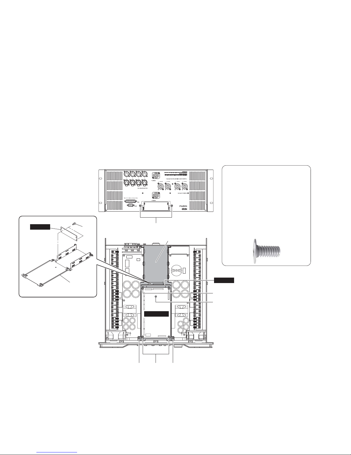
■
DISASSEMBLY PROCEDURES
(分解手順)
[770]: BIND HEAD TAPPING SCREW-S 3x6 MFZN2B3 (--)
S タイト+ BIND
[800]: BIND HEAD TAPPING SCREW-B 4x8 MFZN2B3 (--)
B タイト+ BIND
Fig. 1
(図 1)
1. Top Cover and NX-DFLT Card
(Time required: about 3 minutes)
1-1. Remove the thirteen (13) screws marked [800]. The
top cover can then be removed. (Fig.1)
1-2. Remove the two (2) screws marked [770]. The NX-
DFLT card can then be removed. (Fig. 1)
1. トップカバー、NX-DFLT カード
(所要時間:約 3 分)
1-1. [800]のネジ 13 本を外し、トップカバーを外します。
(図 1)
1-2. [770]のネジ 2 本を外し、NX-DFLT カードを外しま
す。(図 1)
[800]
Top cover
(トップカバ ー )
Top cover
(トップカバ ー )
Top cover
(トップカバ ー )
[800] [800]
[800] [800][770]
NX-DFLT card
(NX-DFLT カード)
NXAMP4x4
25
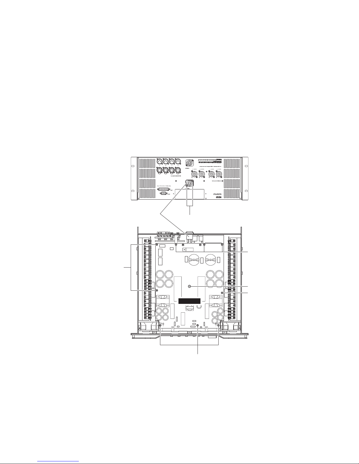
OPT angle
(OPT アングル)
OPT angle
(OPT アングル)
[580][550] [550]
[560]
[555]
[530]
[580]
CONTROL
OPT-AN
OPT-AN
CAUTION
The figure below shows the screw
marked [555] head shape.
To avoid the unit malfunction, make sure
the screw marked [555] head shape is
same as shown below before
assembling the OPT angle.
[555]のネジ頭形状を下図に示します。
動作不良防止のため、OPT アングルを取り
付ける前に、[555]のネジ頭形状が下図のと
おりであることを確認してください。
2. CONTROL Circuit Board, OPT angle and OPTAN Circuit Board
(Time required: about 10 minutes)
2-1. Remove the top cover and the NX-DFLT card.
(See procedure 1.)
2-2. Disconnect the connector assemblies from the
CONTROL circuit board. (Fig. 2)
2-3. Re move the fo ur (4) sc rews ma rked [580]. The
CONTROL circuit board can then be removed. (Fig. 2)
2-4. Remove the two (2) screws marked [550], one (1)
screw marked [555] and the two (2) screws marked
[560]. The OPT angle can then be removed together
with the OPT-AN circuit board. (Fig. 2)
2-5. Remove the two (2) screws marked [530]. The OPT-
AN circuit board and the OPT angle can then be
separated. (Fig. 2)
2. CONTROL シート、OPT アングル、OPT-AN シー
ト(所要時間:約 10 分)
2-1. トップカバー、NX-DFLT カードを外します。
(1 項参照)
2-2. CONTROL シートから束線を外します。(図 2)
2-3. [580]のネジ 4 本を外し、CONTROL シートを外し
ます。(図 2)
2-4. [550]のネジ 2 本、[555]のネジ 1 本、[560]のネ
ジ 2 本を外し、OPT アングルを OPT-AN シートと共
に外します。(図 2)
2-5. [530]のネジ 2 本を外し、OPT-AN シートと OPT
アングルを別けます。(図 2)
[530]: BIND HEAD TAPPING SCREW-S 3x6 MFZN2W3 (--)
S タイト+ BIND
[550]: BIND HEAD TAPPING SCREW-S 3x6 MFZN2W3 (--)
S タイト+ BIND
[555]: BIND HEAD TAPPING SCREW-S 3x6 MFZN2B3 (--)
S タイト+ BIND
[560]: BIND HEAD TAPPING SCREW-S 3x6 MFZN2B3 (--)
S タイト+ BIND
[580]: BIND HEAD TAPPING SCREW-S 3x6 MFZN2W3 (--)
S タイト+ BIND
Fig. 2
(図 2)
NXAMP4x4
26
3. PSANHA シート(所要時間:約 15 分)
3-1. トップカバー、NX-DFLT カードを外します。
(1 項参照)
3-2. CONTROL シート、OPT アングルを外します。
(2 項参照)
3-3. [150A]のネジ 2 本を外し、上側の ACPS 束線を外
します。(図 3)
3-4. PSANHA シートから束線を外します。(図 3)
3-5. [450]のネジ 9 本、[440]の六角スペーサー 1 個を
外し、PSANHA シートを外します。(図 3)
3. PSANHA Circuit Board
(Time required: about 15 minutes)
3-1. Remove the top cover and the NX-DFLT card.
(See procedure 1.)
3-2. Remove the CONTROL circuit board and the OPT
angle. (See procedure 2.)
3-3. Remove the two (2) screws marked [150A], and remove
the upper ACPS connector assembly. (Fig. 3)
3-4. Disconnect the connector assemblies from the
PSANHA circuit board. (Fig. 3)
3-5. Remove the nine (9) screws marked [450] and the
one (1) hexagonal spacer marked [440]. The PSANHA
circuit board can then be removed. (Fig. 3)
[150A]: FLAT HEAD TAPPING SCREW-B 3x8 MFZN2B3 (--)
B タイト+ FLAT
[440]: HEXAGONAL SPACER H=50 B=5.5 (--)
六角スペーサー
[450]: BIND HEAD TAPPING SCREW-S 3x6 MFZN2W3 (--)
S タイト+ BIND
Fig. 3
(図 3)
Upper ACPS connector assembly
(上側の ACPS 束線)
[450]
[150A]
[440]
[450]
[450]
PSANHA
[450]
NXAMP4x4
27
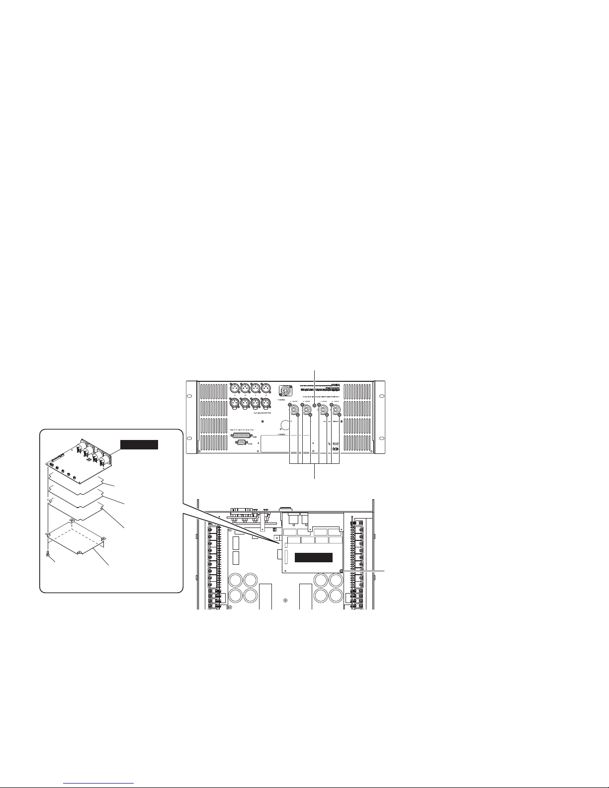
4. OUTANH シート(所要時間:約 20 分)
4-1. トップカバー、NX-DFLT カードを外します。
(1 項参照)
4-2. CONTROL シート、OPT アングルを外します。
(2 項参照)
4-3. PSANHA シートを外します。(3 項参照)
4-4. OUTANH シートから束線を外します。(図 4)
4-5. [320]のネジ 8 本、[330]のネジ 1 本、[325]のネ
ジ 1 本を外し、OUTANH シートを絶縁シート 2 枚、
シールド 2 枚と共に外します。(図 4)
4-6. [317]のプラスチックリベット3個を外し、
OUTANH シートを絶縁シート 2 枚とこれらのシート
に貼付されたシールド 2 枚から別けます。(図 4)
注: 絶縁シート 2 枚とシールド 2 枚は、両面テー
プで互いに貼り付けられているために分離す
ることはできません。
4. OUTANH Circuit Board
(Time required: about 20 minutes)
4-1. Remove the top cover and the NX-DFLT card.
(See procedure 1.)
4-2. Remove the CONTROL circuit board and the OPT
angle. (See procedure 2.)
4-3. Remove the PSANHA circuit board. (See procedure 3.)
4-4. Disconnect the connector assemblies from the
OUTANH circuit board. (Fig. 4)
4-5. Remove the eight (8) screws marked [320], the one
(1) screw marked [330] and the one (1) screw marked
[325]. The OUTANH circuit board can then be removed
together with the two (2) insulation sheets and the two
(2) shields. (Fig. 4)
4-6. Remove the three (3) plastic rivets marked [317]. The
OUTANH circuit board can be separated from the two
(2) insulation sheets and the two (2) shields attached
to them. (Fig. 4)
Note: The two (2) insulation sheets and the two (2)
shields can not be separated because they are
attached each other with both side adhesive
tapes.
[317]: PLASTIC RIVET NRP-345 (--)
プラスチックリベット
[320]: FLAT HEAD TAPPING SCREW-B 3x8 MFZN2B3 (--)
B タイト+ FLAT
[325]: BIND HEAD TAPPING SCREW-S 3x6 MFZN2W3 (--)
S タイト+ BIND
[330]: BIND HEAD TAPPING SCREW-B 3x8 MFZN2B3 (--)
B タイト+ BIND
Fig. 4
(図 4)
[320]
[325]
[317]
OUTANH
OUTANH
Insulation sheet 1
(絶縁シート 1)
Insulation sheet 2
(絶縁シート 2)
Shield 1
(シールド 1)
Shield 2
(シールド 2)
[330]
NXAMP4x4
28

Lower ACPS connector assembly
(下側の ACPS 束線)
[150B]
PSANHB
[90] [100][100]
[95]
[90]
[90]
[100]
[90]
PS angle 1
(PS アングル 1)
PS angle 2
(PS アングル 2)
GND angle
(GND アングル)
[390]
[396]
[410]
5. PSANHB シート(所要時間:約 25 分)
5-1. トップカバー、NX-DFLT カードを外します。
(1 項参照)
5-2. CONTROL シート、OPT アングルを外します。
(2 項参照)
5-3. PSANHA シートを外します。(3 項参照)
5-4. OUTANH シートを外します。(4 項参照)
5-5. [150B]のネジ 2 本を外し、下側の ACPS 束線を外
します。(図 5)
5-6. [390]のネジ 2 本を外し、PS アングル 1 を外します。
(図 5)
5-7. [396]のネジ 1 本を外し、GND アングルを外します。
(図 5)
5-8. [410]のネジ 2 本を外し、2 つの PS アングル 2 を
外します。(図 5)
5-9. PSANHB シートから束線を外します。(図 5)
5-10.[100]のネジ 5 本、[90]の六角スペーサー 5 個、[95]
の六角スペーサー 1 個を外し、PSANHB シートを外
します。(図 5)
5. PSANHB Circuit Board
(Time required: about 25 minutes)
5-1. Remove the top cover and the NX-DFLT card.
(See procedure 1.)
5-2. Remove the CONTROL circuit Board and the OPT
angle. (See procedure 2.)
5-3. Remove the PSANHA circuit Board. (See procedure 3.)
5-4. Remove the OUTANH circuit Board. (See procedure 4.)
5-5. Remove the two (2) screws marked [150B], and remove
the lower ACPS connector assembly. (Fig. 5)
5-6. Remove the two (2) screws marked [390], and remove
the PS Angle 1. (Fig. 5)
5-7. Remove the one (1) screw marked [396], and remove
the GND Angle. (Fig. 5)
5-8. Remove the two (2) screws marked [410], and remove
the two (2) pieces of PS Angle 2. (Fig. 5)
5-9. Disconnect the connector assemblies from the
PSANHB circuit board. (Fig. 5)
5-10. Remove the five (5) screws marked [100], the five
(5) hexagonal spacers marked [90] and the one (1)
hexagonal spacer marked [95]. The PSANHB circuit
board can then be removed. (Fig. 5)
Fig. 5
(図 5)
[90]: HEXAGONAL SPACER H=81.4 B=5.5 (--)
六角スペーサー
[95]: HEXAGONAL SPACER H=41 B=5.5 (--)
六角スペーサー
[100]: BIND HEAD TAPPING SCREW-S 3x6 MFZN2W3 (--)
S タイト+ BIND
[150]: FLAT HEAD TAPPING SCREW-B 3x8 MFZN2B3 (--)
B タイト+ FLAT
[390]: BIND HEAD TAPPING SCREW-S 3x6 MFZN2B3 (--)
S タイト+ BIND
[396]: BIND HEAD TAPPING SCREW-S 3x6 MFZN2B3 (--)
S タイト+ BIND
[410]: BIND HEAD TAPPING SCREW-S 3x6 MFZN2W3 (--)
S タイト+ BIND
NXAMP4x4
29
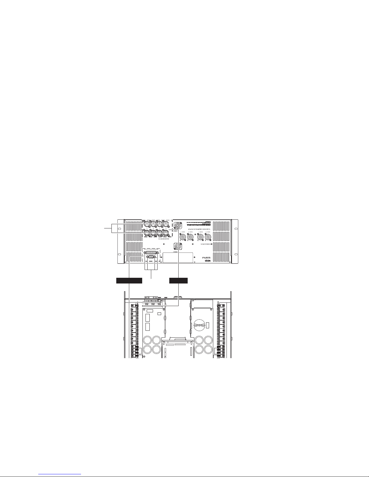
[370]
RS232-GPI
[70]
INANH
6. INANH Circuit Board
(Time required: about 7minutes)
6-1. Remove the top cover and the NX-DFLT card.
(See procedure 1.)
6-2. Disconnect the connector assembly from the INANH
circuit board. (Fig. 6)
6-3. Remove the sixteen (16) screws marked [70]. The
INANH circuit board can then be removed. (Fig. 6)
7. RS232-GPI Circuit Board
(Time required: about 7 minutes)
7-1. Remove the top cover and the NX-DFLT card.
(See procedure 1.)
7-2. Disconnect the flat cable from the RS232-GPI circuit
board. (Fig. 6)
7-3. Remove the four (4) hexagonal lock screws marked
[370]. The RS232-GPI circuit board can then be
removed. (Fig. 6)
6. INANH シート(所要時間:約 7 分)
6-1. トップカバー、NX-DFLT カードを外します。
(1 項参照)
6-2. INANH シートから束線を外します。(図 6)
6-3. [70]のネジ 16 本を外し、INANH シートを外します。
(図 6)
7. RS232-GPI シート(所要時間:約 7 分)
7-1. トップカバー、NX-DFLT カードを外します。
(1 項参照)
7-2. RS232-GPI シートからフラットケーブルを外します。
(図 6)
7-3. [370]の六角ロックネジ 4 本を外し、RS232-GPI シー
トを外します。(図 6)
[70]: BIND HEAD TAPPING SCREW-B 2.6x8 MFZN2B3 (--)
B タイト+ BIND
[370]: HEXAGONAL LOCK SCREW (--)
6 角ロックネジ
Fig. 6
(図 6)
NXAMP4x4
30
 Loading...