


NX242 Digital TDcontroller
Service Manual
___________________________________________________________________________________________________
NEXO NX242 DIGITAL TDcontr oller S ervice manual r ev10060 6
P.
2
Declaration of conformity
This equipment has been tested and found to comply with the safety objectives and essential requirements of European (73/23/EEC and
89/336/EEC directives) and international Standards, by fulfilling the requirements of the following harmonized standards:
Electrical Safety (EU) : IEC 60065 (12/2001) Audio, video and similar electronic apparatus
Electrical Safety (US) : UL60065 Seventh Edition, dated June 30, 2003 category AZSQ, E241312.
Electrical Safety (CAN) : CSA-C22.2 N°60065:03 Edition, dated April 2003 category AZSQ7, E241312
10CE
A
udio Equipment
10CE
A
udio Equipment
Electrical Safety (Rest of the World) : CB test certificate DK-8371 based on IEC60065-2001 7nd ed. with all national deviation s.
Radiated Emission (EU) : EN55103-1 (1996) Electromagnetic compatibility - Product family standard for audio, video, audiovisual and entertainment lighting control apparatus for professional use.
Radiated Emission (US) : FFC part15 class B
Radiated Emission (CAN) : This Class B digital apparatus complies with Canadian ICES-003.
RF Immunity (EU) : EN55103-2 (1996) Electromagnetic compatibility - Product family standard for audio, video, audio-visual and
entertainment lighting control apparatus for professional use.
Note: EMC conformance testing is based on the use of recommended cable types. The use of other cable types may degrade EMC
performances.
IMPORTANT SAFETY INSTRUCTIONS
1) Read these instructions.
2) Keep these instructions.
3) Heed all warnings.
4) Follow all instructions.
5) Do not use this apparatus near water.
6) Clean only with dry cloth.
7) Do not block any ventilation openings. Install in accordance with the
manufacturer’s instructions.
8) Do not install near any heat sources such as radiators, heat registers, stoves, or
other apparatus (including amplifiers) that produce heat.
9) Do not defeat the safety purpose of the polarized or grounding-type plug. A
polarized plug has two blades with one wider than the other. A grou nding type plug
has two blades and a third grounding prong. The wide blade or the third prong are
provided for your safety. If the provided plug does not fit into your outlet, consult an
electrician for replacement of the obsolete outlet. (US market)
10) Protect the power cord from being walked on or pinched particularly at plugs,
convenience receptacles, and the point where they exit from the apparatus.
11) Only use attachments/accessories specified by the manufacturer.
13) Unplug this apparatus during lightning storms or when unused for long periods of
time.
14) Refer all servicing to qualified service personnel. Servicing is required when the
apparatus has been damaged in any way, such as power-supply cord or plug is
damaged, liquid has been spilled or objects have fallen into the ap paratus, the
apparatus has been exposed to rain or moisture, does not operate normally, or has
been dropped.
Information about products that generate electrical noise :
NOTE: The United States Federal Communications Commission (in 47 CFR 15.105)
has specified that the following notice be brought to the attention of users of this
product:
This equipment has been tested a nd found to comply with the limits for a Class B
digital device, pursuant to Part 15 of the FCC Rules. These limits are de sign ed to
provide reasonable protection against harmful interference in a residential installation.
This equipment generates, uses and can radiate radio frequency energy and, if not
installed and used in accordance with the instructions, may cause harmful interference
to radio communications. However, there is no guarantee that interference will not
occur in a particular installation. If this equipment does cause harmful interference to
radio or television reception, which can be determined by turning the equipment off
and on, the user is encouraged to try to correct the inte rfe rence by one or more of the
following measures:
- Reorient or relocate the receiving antenna.
- Increase the separation between the equipment and receiver.
- Connect the equipment into an outlet on a circuit different from that to which the
receiver is connected.
- Consult the dealer or an experienced radio/TV technician for help.
The user may find the following booklet, prepared by the Federal Communications
Commission, helpful: How to identify and Resolve Radio/TV Interference Problems.
This booklet is available from the U.S. Government Printing Office, Washington,
D.C. 20402, Stock No. 004-000-00345-4. Use of a shielded cable is required to
comply within Class B limits of Part 15 of FCC Rules. Pursuant to Part 15.2 1 of the
FCC Rules, any changes or modifications to this equipment not expre ssly approved by
NEXO S.A. may cause, harmful interference and void the FCC authorization to
operate this equipment.
To avoid electrical shock, do not remove covers.
Dangerous voltages exist inside.
Refer all servicing to qualified personnel only.
WARNING: To reduce the risk of fire or electric shock,
do not expose this apparatus to rain or moisture.
RISK OF ELECTRIC SHOCK
DO NOT OPEN
CAUTION
The lightning flash with arrowhead
symbol, within an equilateral triangle
is intended to alert the user to the
presence of uninsulated “dangerous
voltage” within the product's
enclosure that may be of sufficient
magnitude to constitute a risk of
electric shock to persons.
The exclamation point within an
equilateral triangle is intended to
alert the user to the presence of
important operating and
maintenance (servicing) instructions
in the literature accompanying
the appliance.
WARNING ! This appliance is a CLASS 1 apparatus and must be earthed.
The green and yellow wire of the mains cord must always be connected to an installation safety earth or ground. The earth is essential for
personal safety as well as the correct operation of the system, and is internally connected to all exposed metal surfaces. Additional
recommendation for interconnection to other equipment can be found in the FOREWORD at the beginning of this manual

P.
3
___________________________________________________________________________________________________
NEXO NX242 DIGITAL TDcontr oller S ervice manual r ev10060 6
Table of content
IMPORTANT SAFETY INSTRUCTIONS.........................................................................................................................2
FOREWORD..........................................................................................................................................................................4
SAFETY INSTRUCTION.....................................................................................................................................................4
HISTORY................................................................................................................................................................................5
MECHANICAL ISSUES ....................................................................................................................................................... 6
REMOVING THE TOP PANEL.....................................................................................................................................................6
REMOVING THE PCB...............................................................................................................................................................6
HARDWARE PROBLEM ON NX242 S.N. 3880 TO 4049.................................................................................................7
ABSTRACT ................................................................................................................................................................................7
HARDWARE CORRECTION .......................................................................................................................................................7
HARDWARE FIX FOR THE NXTENSION-CAI AND THE NXTENSION-ES4.........................................................11
ABSTRACT ..............................................................................................................................................................................11
HARDWARE CORRECTION .....................................................................................................................................................11
PART LIST...........................................................................................................................................................................14
CRITICAL COMPONENTS........................................................................................................................................................14
SCHEMATICS.....................................................................................................................................................................26
___________________________________________________________________________________________________
NEXO NX242 DIGITAL TDcontr oller S ervice manual r ev10060 6
P.
4
Foreword
CAUTION !
This servicing instruction is for use by qual ified servi ce personnel only. To reduce the risk of electric shock
do not perform any servicing other than that contained in the operating instructions unless you are
qualified to do so.
Safety instruction
Mains Power
WARNING ! THIS APPLIANCE MUST BE EARTHED.
The green and yellow wire of the mains cord must always be connected to an installation safety earth or
ground. The earth is essential for personal safety as well as the correct installation of the system, and is
internally connected to all exposed metal surfaces. Any rack framework into which this unit may be
mounted is assumed to be connected to the same grounding ci rcuit. (see also p.4)
NEXO TDcontrollers don’t provide a mean to switch off the unit from the front pa nel. A s they are inte nde d
to be rack mounted the back panel is not accessible during use. There fore it is left to the us er to pro vide a
disconnection mean readily operable.
Voltage setting
NEXO TDcontrollers use a switch mode power supply (SMPS). This SMPS acc ep ts u n i versal AC power
input voltages in the range 90V to 264V, and requires no manual adjustment for voltages in this range.
Mounting the TDcontroller in a rack (G rounding, shielding & safety issues)
The TDcontroller is intended for rack mounting. The only accessible part during use shall be the front
panel of the TDcontroller. Any space above or under the TDcontroller shall be obstructed with a blank
panel.
The rack is a free grounding and shielding structure and it provides extra shielding. Therefore, it is
desirable that the screws used to fix the TDcontroller in the frame or rack provide an electrical contact
between the chassis of the TDcontroller an d the rack.
The primary reason for grounding is safety. Co nforman ce to t he appli cable req uirem ent s of the authoritie s
having jurisdiction is, of course, mandatory. However, grounding also has an impact on electromagnetic
compatibility. From the EMC point of view, it is desirable to have a low impedance ground network, as a
current flowing in the ground network will then produce low voltage in the network. A low impedance
network can be obtained using a multipoint ground scheme, with as many closed ground loops as is
economically possible.
Fuse
The fuse provided in the unit will not blow during normal operation. If the fuse blows the TDcontroller
has malfunctioned. This fuse must only be ch anged by NEXO ce rtified service personnel. In a ny case do
not replace the fuse with a non-certified NEXO fuse, as this will invalidate the NEXO warranty.

___________________________________________________________________________________________________
NEXO NX242 DIGITAL TDcont roller S ervic e manual rev100 606
P.
5
History
Partlist PCB ref note S/N Date
V1.0 NX242 V1.8 initial
NX242 V2.0 Minor points fixed for
UL approval
___________________________________________________________________________________________________
NEXO NX242 DIGITAL TDcontr oller S ervice manual rev 10060 6
P.
6
Mechanical issues
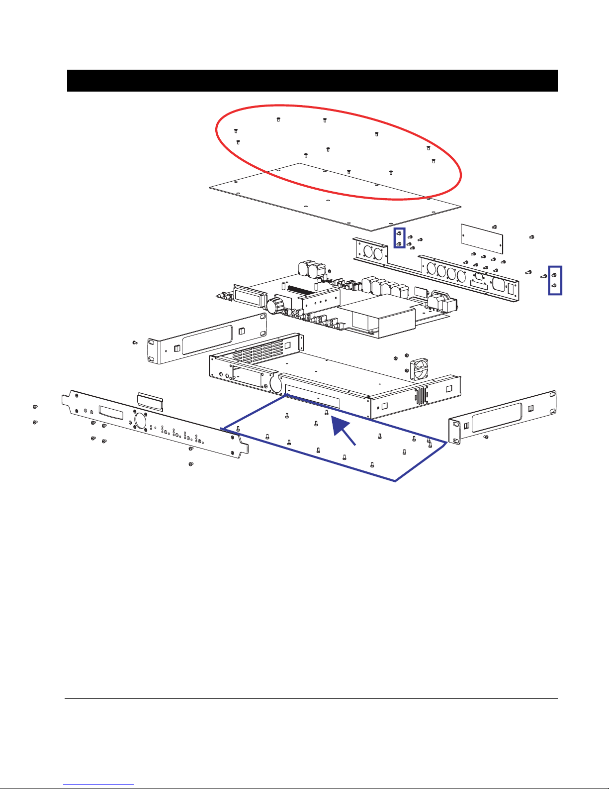
Removing the top panel
First be sure that the NX242 is disconnected from the m ains. Wait 5 minute s to discharge the capa citors
To remove the top panel; unscrew the 11 screws circled in red in the above drawing (POZIDRIVE screwdriver).
When replacing the top panel pay attention to the 2 screws which are above the aluminum heatsink. They
should be screwed with a lesser torque than the other to avoid damagi ng the aluminum th reading.
WARNING: Some of the NX components are sensitive to electros tatic discharges. Be sure to firmly hold the
chassis of the NX242 before touching any component inside. Always keep contact with the chassis to prevent
electrostatic discharge. If possible, use non-magnetic tools.
Removing the PCB
The remove the PCB; unscrew the 14 screws in blue square (POZIDRIVE screwdriver). Warning : the screw
pointed by the arrow is smaller than the other. It must be replace at the very same place to avoid so short circuit
problem (affecting slightly the overall dynamic range) on PCB v1.8
___________________________________________________________________________________________________
NEXO NX242 DIGITAL TDcontr oller S ervice manual rev 10060 6
P.
7
Hardware problem on NX242 s.n. 3880 to 4049
Abstract
This document deals with a hardware problem that can be found on any NX242 from serial number 3880 to
4049.
The symptoms of this failure is the following:
- Crackles on the outputs patched on the A Input of the NX242 that ca n be very audibl e.
- Blinking of the Sense green LED even without amplifier connected.
Please note that in case of emergency it is always possible to use the B input of the NX242 that does not
present noise.
Also note that in most of the cases, the noise di sappears after a few mi nutes (after the NX warmed up ).
The solution to solve this problem is to remove faulty capacitors on the NX 242 PCB.
Hardware correction
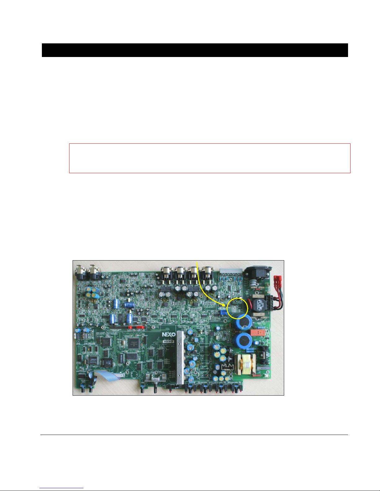
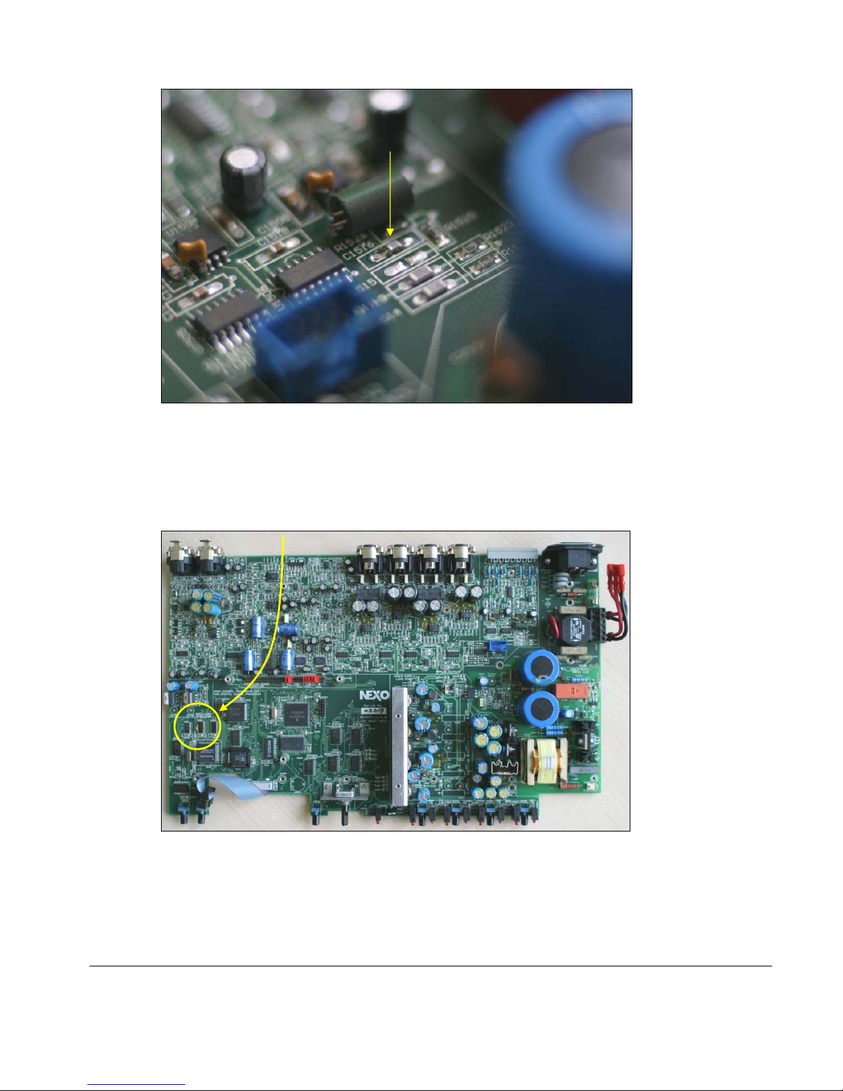
Finding and removing the C1516 co mponent
The C1516 component has been soldered on a few NX242 from serial number 3880 to 4049. In most of the
cases, this component is not present on the motherboard. If not, ple ase go on to the next chapter.
Locate the C1516 component inside the NX242.
The C1516 is a SMD capacitor.
Here is a closer look on the C1516 compo nent, near the connector for t he RS-232 Interfa ce.
___________________________________________________________________________________________________
NEXO NX242 DIGITAL TDcontr oller S ervice manual rev 10060 6
P.
8
Remove this component with a soldering iron. Be sure to let a clear path between the two pad s of the PCB. The
footprint should look like the footprint of the component C1515 just b ellow.
Finding and removing the “Flying” capacitor
First of all locate the Flying capacitor, on the picture bell ow:
Now have a closer look on the component U5401. This component has a traditional capacitor, that can be blue
or orange soldered between the pin 2 and t he pin 8, as you can see on the pict ure bellow.

___________________________________________________________________________________________________
NEXO NX242 DIGITAL TDcontr oller S ervice manual rev 10060 6
P.
9
Please note that the color of the capacitor has no importance.
Now, please check the manufacturer of the U5401 component. From NX242 serial number 3200 to 3879, the
component should be a Texas Instrument, and from serial number 3880 to 4049, the component should be a
Philips. Here are two pictures of the possible manufacturer:
The Texas Instrument component:
The Philips component:

___________________________________________________________________________________________________
NEXO NX242 DIGITAL TDcont roller S ervic e manual rev100 606
P.1
0
Only if you have a Philips component, you have to remov e the added cap acitor
You can unsolder the capacitor, or simply cut the legs as near as possible to t he legs of the Philips component.
If you have a Texas
component, you must have the capacitor betwee n the pin 2 and the pin 8 of U5401.
Once this operation is finished, replace the cover of the NX242, with all of the screws, as they are important for
the shielding of the digital section of the controller. When you power up the unit again, it should boot normally,
and none of your settings should be lost. Check that the noise has disappeared on all the outputs (be sure to
check the input A of the controller).
___________________________________________________________________________________________________
NEXO NX242 DIGITAL TDcontr oller S ervice manual rev 10060 6
P.11
Hardware fix for the Nxtension-CAI and the Nxtension-ES4
Abstract
This document deals with a hardware problem that can be fou nd on Nxtension card with:
- Serial number up to 695 for Nxtension-ES4
- Serial number up to 299 for Nxtension-CAI
The symptoms of this failure are the following:
- Crackles or noise on all the outputs that can be permanent or punctual.
- When using an Nxtension-ES4, the noise disappea rs when switching from Analog to Digital input.
Also note that this problem mostly occurs with Nxtension-CAI cards.
The solution is to connect to a fixed potential a pin on the Nxtension board whi ch was left floating.
Hardware correction
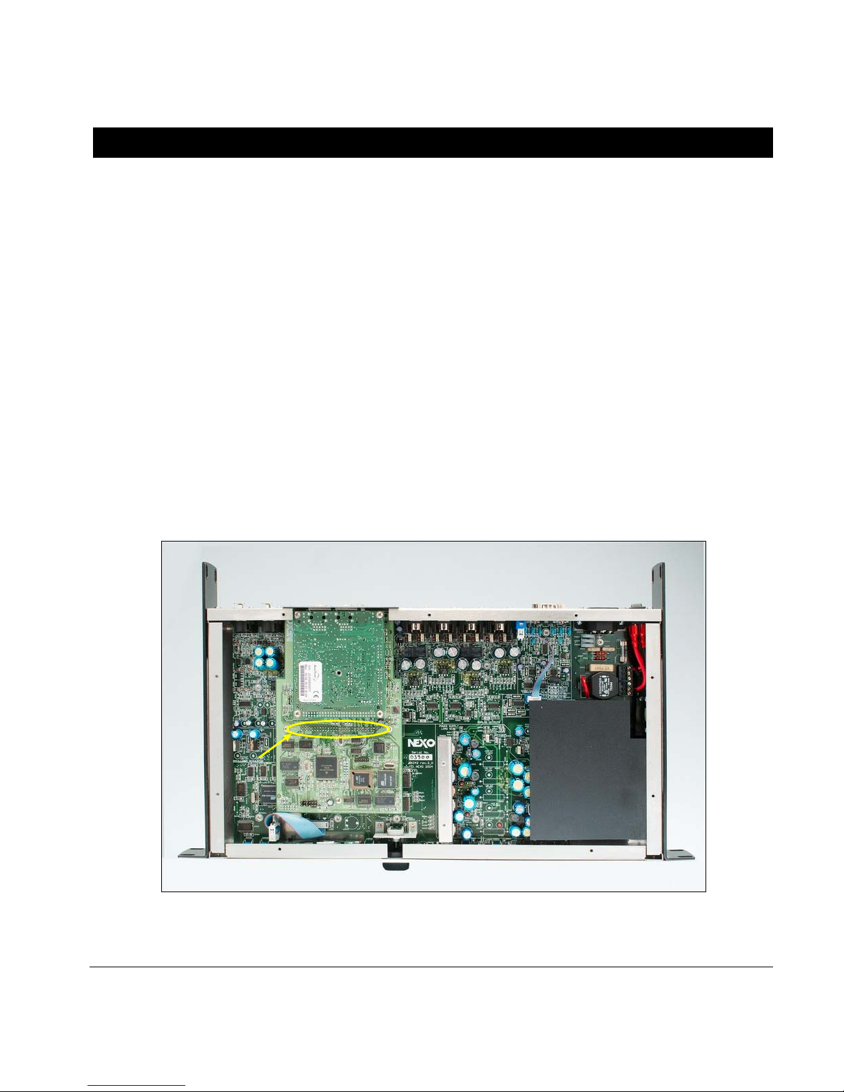
First and foremost, be sure to disconnect the NX242 from the mains before opening the top cover. Once the top
cover of the NX242 is open, you can directly do the hardware correction on t he Nxtension -board itself.
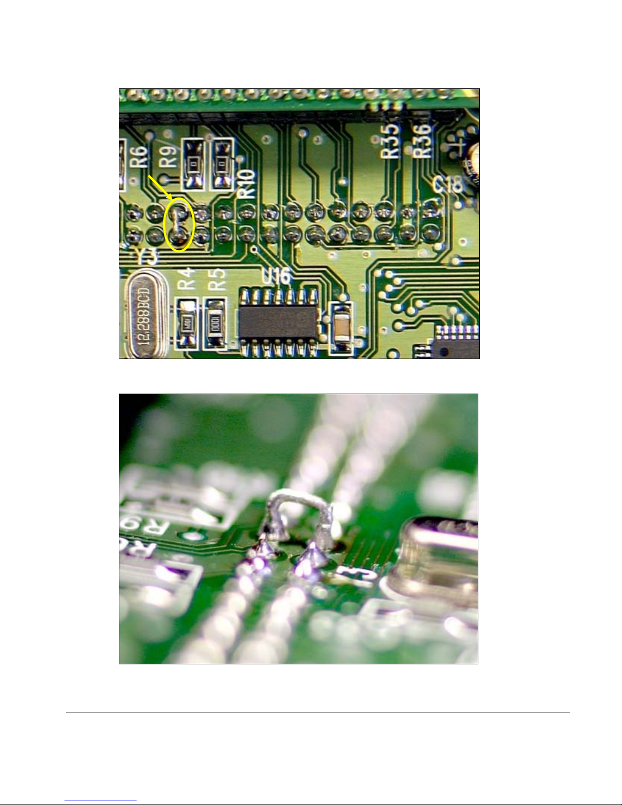
Then locate the large header on the Nxtension card like on the picture above. On this header, you will have to
solder a jumper between two pins (one next to the other). These two pins are located 17 pins from the left or 12
pins from the right (see the picture bellow).
___________________________________________________________________________________________________
NEXO NX242 DIGITAL TDcontr oller S ervice manual rev 10060 6
P.1
2
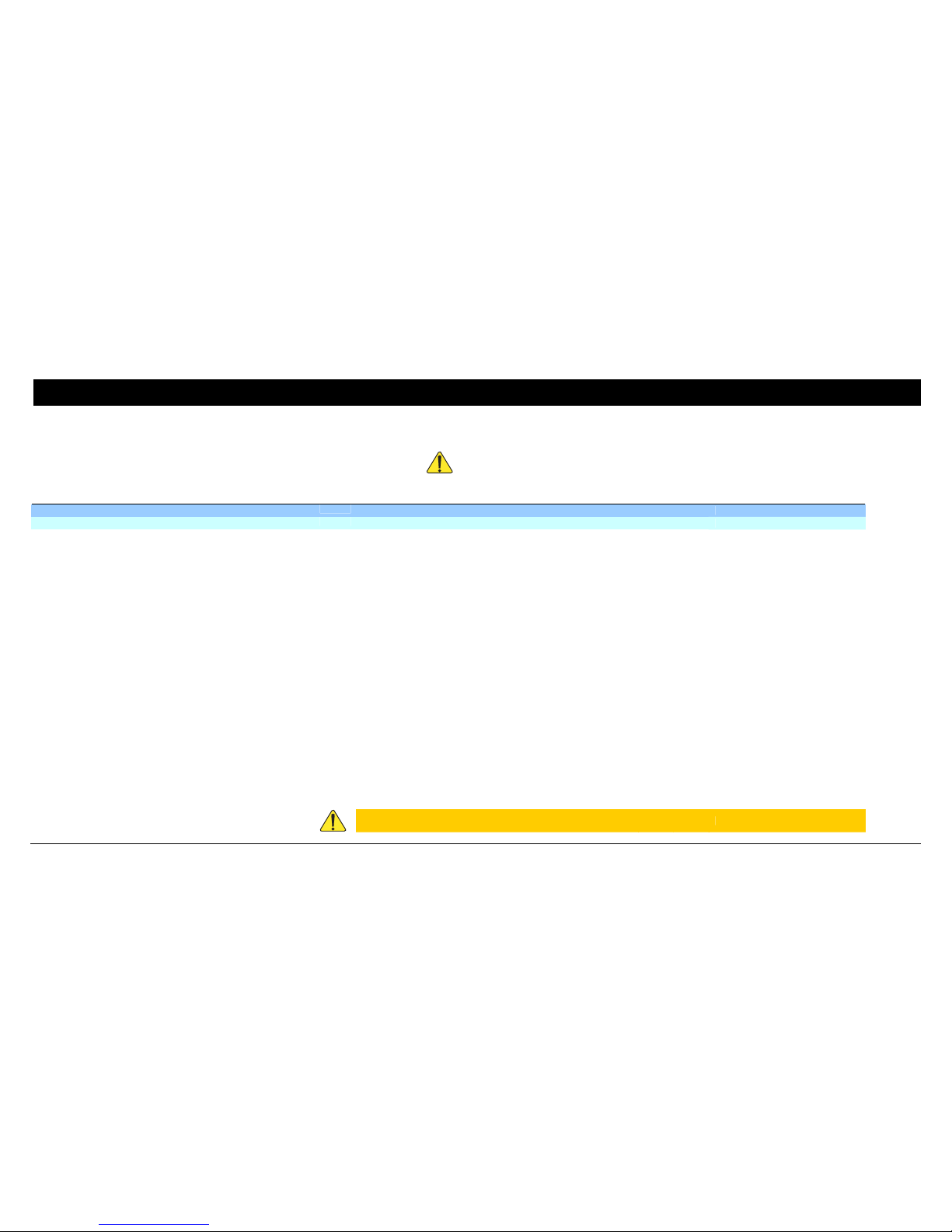
Bellow is a side view of the soldering: a hard wire is the best solution has it will be less sensible to vibration.
Once it is done, screw the cover back, and check that the NX is booting normally. Check that the audio is
passing through without any problem.

___________________________________________________________________________________________________
NEXO NX242 DIGITAL TDcont roller S ervic e manual rev100 606
P.1
3
___________________________________________________________________________________________________
NEXO NX242 DIGITAL TDcontroller S ervice manual r ev10060 6
P.1
4
Part list
Critical components
Due to the UL and CB scheme certifications the components marked
shall never be changed with an equivalent part (unless stated in the list below). In case of failure,
the exact same type and reference shall be used. Failing to do so will void th e warranty and the UL re sponsibility and certification.
PCB reference Qty
Reference
Power Supply
L2504
1 Choke, high power, Inductance, radial
10 uH
Panasonic - ELC08D100E
Q2502 1 Hexfet Power MOSF ET
International Rectifier - IRFBE30
Q2501 1 Transistor power TO-220, TIP50
On Semiconductor - TIP50
D2501 D2506 2
Diode, Ultra fast Power rectifier Motorola - MURS160T3
D2504 D2505 2
Diode, schottky power rectifier ST - STPS340U
D2509 1 Diode, Schottky Rectifier, TO220
International Rectifier - 43CTQ100
L2501 1 Choke, EMI suppression, ferrirte core, AXIAL, 800mA, 10%
47 uH Epcos - B82144A2473J000
L2502 L2503 2
Choke, high power, 1.3A, RADIAL 47 uH Panasonic - ELC08D47U
D2507 D2508 2
Diode, Rectifier, Utrafast, rugged, SOT78 case Philips - BYQ28E200
C2604 C2605 C2606 C2607 C2501 C2503 6
Capacitor, Thru Hole, Electrolytic, Radial, 105°C, Low Z, p=3.5mm rating
35V
100 u
BC components - 2222 135 30101
C2521 C2522 C2523 C2524 C2525 C2526 6
Capacitor, electrolytic, Radial, 105°C, Very Low Impedance 470uF 50V (136
RVI) d=12.5mm p=5mm
470 u
BC components - 2222 136 31471
C2514 C2515 C2516 C2517 C2518 C2601 C2602
C2603
8
Capacitor, electrolytic, Radial, 105°C, Very Low Impedance 470UF 16V
(136 RVI) d=10mm p=5mm
470 u
BC components - 2222 136 35471
C2505 C2506 2
Capacitor, Non Solid AI-electrolytic, Power long life, Snap in, 100uF, 400V
(PLL-SI 059 CASE3030)
100 u
BC components - 2222 059 56101
C2508 1 Capacitor, Thru Hole, ceramic class 2 rating=1000V, p=5,08mm tol 20% 2.2 n BC components - 2252 601 ..226
C2502 1
Capacitor, Thru Hole, Polyester MKT Film Capacitor p=22.5mm tol 10%,
rating=630V
100 n Vishay MKT1822-410-63

___________________________________________________________________________________________________
NEXO NX242 DIGITAL TDcontroller S ervice manual r ev10060 6
P.1
5
C0033 C0034 2
Capacitor, EMI suppressor, class X2, metallized paper, 0.1uF, p=20.3mm 0.1 u Evox Rifa PME271M610M
C0029 C0030 C0031 C0032 4
Capacitor, EMI suppressor, class Y2, metallized paper, 2.2nF, p=10.2mm 2.2 n Evox Rifa PME271Y422M
C2511 C2512 2
Capacitor, Thru Hole, ceramic low loss class 1 rating 1000V p=5.08mm 47 p BC component - 2252 561 ..406
R0017 R0026 2
Resistor, Power, 2W, rating 500V, IEC 60115-1 IEC 60115-4 1 M BC components - 2206 198 03015
TR2501 1
Flyback Transformer SIM NX242/01
FUS0001
2 Fuse Holder for diam. 5mm fuse, pitch 5mm
shurter 231683
ME2509 1 Heat sink for TO220 14°C/W of PSTDmk3
ME2506 1
Heat sink for TO220 20°C/W FROM THERMALLOY REF FARNELL 178700
ME2507 ME2508 2
Heat sink for TO220 30°C/W OF PSTDMK3
ME0015 1 Heat sink with 5 places, without solder mask
Nexo Custom
CN0008 1
AC Inlet O.HEIL 1001-X-4460
U2604
1 Negative voltage regulator 79XX TO220
ST - L7918CV
U2605 1 Positive voltage regulator LMXX TO220
ST - LM337SP
BR2501 1 Rectifier Bridge, 1A Singl e P hase D.I.L.
International Rectifier - DF06S
U2602 U2603 2
Regulator, 1A Low Dropout Regulator National semiconductor - LM2940CT-5.0
U2606 1 Positive regulator 78XX TO220
ST - L7818CV
U2601 U2607 2
Positive regulator type LM317 TO220 National semiconductor - LM317T
1
Primary switch, double pole,250Vac 10A, 1E4, V-0,category D (GW 805°C) Arcolectric Switch H8550VB
U2501
1 PWM Controller, Current Mode
Texas instrument - UC3844AD8
D1001 D2601 D2602 D2603 D2604 D2605 6
Rectifier, General purpose Philips - BYD17G/T1
RL2501 1
Relay DPDT Schrack RT Schrack - RT424012
U2503 1
Phototransistor optocoupler Fairchild - CNY17-2.3S
TH0001 TH0002 TH0003 3
Thermistor PTC for overload protection 320mA Vmax=265V BC Component - 2322 662 53213
VDR0001
1 Varistor, Radial, line voltage operation
Harris/Littelfuse - V320LA40B
CN0009 1
Socket connector Plug-in 130 series 6 poles, p=5mm Imo - Plugin 20.130/6
1
Pin Strip for socket connector Imo - Plugin 20.130/PS
2
AWG16 (1.5mm²),600V, 105°C, Orange wire L=70mm, UL AVLV2
[connecting CN0009 to mains switch]
CAEDATA FDC-UL1007.16
 Loading...