

Page 1
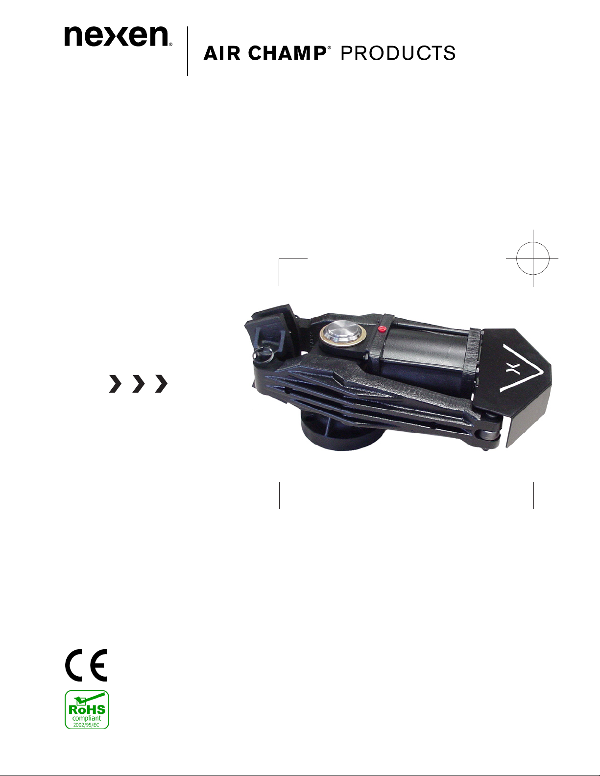
Single Post Caliper Brake
VC500
1
FORM NO. L-21156-F-0209
Page 2
In accordance with Nexen’s established policy of constant product improvement, the specifications contained in this
Read this manual carefully before installation and operation.
Follow Nexen’s instructions and integrate this unit into your
system with care. This unit should be installed, operated and
maintained by qualified personnel ONLY. Improper installation
can damage your system, cause injury or death. Comply with
all applicable codes.
DANGER
manual are subject to change without notice. Technical data listed in this manual are based on the latest information
available at the time of printing and are also subject to change without notice.
Technical Support: 800-843-7445
(651) 484-5900
www.nexengroup.com
This document is the original, non-translated, version.
Conformity Declaration: In accordance with Appendix II B of CE Machinery Directive (2006/42/EC):
A Declaration of Incorporation of Partly Completed Machinery evaluation for the applicable EU directives
was carried out for this product in accordance with the Machinery Directive. The declaration of incorporation
is set out in writing in a separate document and can be requested if required.
This machinery is incomplete and must not be put into service until the machinery into which it is to be
incorporated has been declared in conformity with the applicable provisions of the Directive.
Copyright 2009 Nexen Group, Inc.
FORM NO. L-21156-F-0209
Nexen Group, Inc.
560 Oak Grove Parkway
Vadnais Heights, Minnesota 55127
ISO 9001 Certified
2
Page 3

Table of Contents
General Specifications -----------------------------------------------------------------------------------------------------------------------4
General Safety Precautions -----------------------------------------------------------------------------------------------------------------4
Installation -----------------------------------------------------------------------------------------------------------------------------------------5
Friction Facing Adjustment -----------------------------------------------------------------------------------------------------------------7
Air Connections -------------------------------------------------------------------------------------------------------------------------------8
Lubrication ----------------------------------------------------------------------------------------------------------------------------------------8
Operational Modes -----------------------------------------------------------------------------------------------------------------------------9
Maintenance ------------------------------------------------------------------------------------------------------------------------------------10
Parts Replacement --------------------------------------------------------------------------------------------------------------------------11
Replacement Parts ---------------------------------------------------------------------------------------------------------------------------13
Parts List ----------------------------------------------------------------------------------------------------------------------------------------13
Warranty -----------------------------------------------------------------------------------------------------------------------------------------14
3
FORM NO. L-21156-F-0209
Page 4
GENERAL SPECIFICATIONS
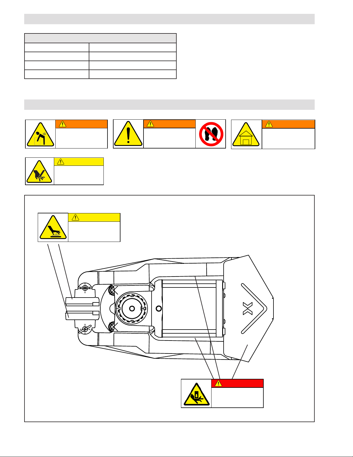
WARNING
Keep indoors. This product is
intended for indoor environments
only. Use of the brake outdoors
will damage components.
WARNING
Heavy object. To avoid injury,
use lifting aids and proper lifting
techniques when installing,
removing or replacing.
DANGER
WARNING
Do not stand on the brake guard
(or any other part) of the unit.
The components may fail and
cause severe injury or death.
CAUTION
Hot surface.
Do not touch.
CAUTION
Watch for sharp features when
installing and servicing the brake.
The brake has complex and
machined edges.
Specifications
Torque: Up to 4785.9 Nm (42,350 in-lb)
Min. Release Pressure: 4.1 bar (60 psi)
Service Temperature: 4.5 - 50 C (40 - 120 F)
Approximate Weight: 50.8 kg (112 lbs)
GENERAL SAFETY PRECAUTIONS
FORM NO. L-21156-F-0209
Due to high spring forces and
possible pinch points, always
keep hands and fingers out of
the linkage assembly area,
4
Page 5
INSTALLATION
DIAMETER
mm [inches]
PRODUCT
NO.
QD
BUSHING
TORQUE
Nm [ft-lb]
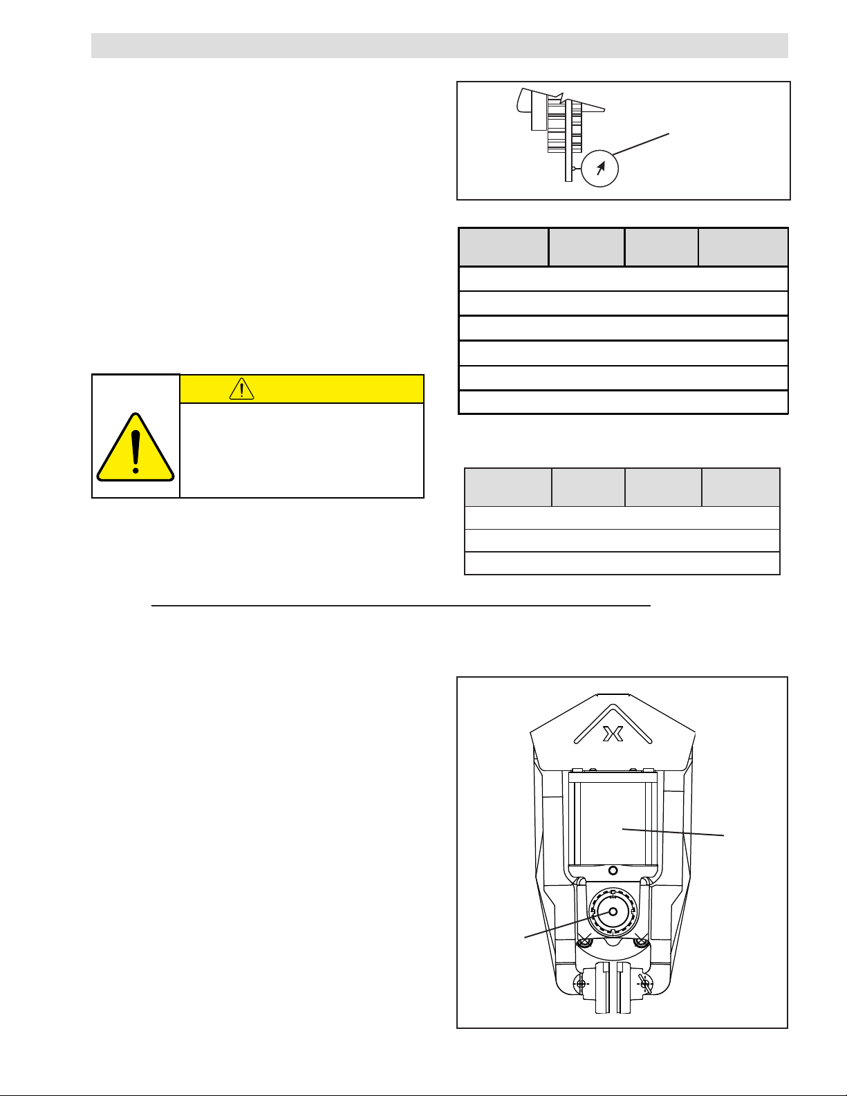
356 [14] 934202 E 81 [60]
406 [16] 934203 E 81 [60]
457 [18] 934204 J 182.5 [135]
508 [20] 934205 J 182.5 [135]
559 [22] 934206 J 182.5 [135]
610 [24] 934207 J 182.5 [135]
RETEMAID
]sehcni[mm
TCUDORP
.ON
DQ
GNIHSUB
EUQROT
]bl-tf[mN
]52.81[464002439J ]531[5.281
]12[335003439J ]531[5.281
]42[016004439J ]531[5.281
CAUTION
DISC
1. Thoroughly inspect the tapered bore of the disc hub
and tapered surface of the Q.D. bushing. Remove
any dirt, grease, or foreign material. Do not use
lubricants for this installation.
2. Insert the Q.D. bushing into the disc hub, aligning
the untapped holes in the bushing flange with the
tapped holes in the disc hub.
3. Insert the pull-up bolts and tighten to the
recommended torque (See Tables 1 and 2).
NOTE: Runout is minimized if a dial indicator is used
as the pull-up bolts are tightened. Place contact tip of
the Dial Indicator on the machined surface of the Rotor
to measure runout. Runout should be less than 0.254-
0.381 mm [0.010-0.015 inches] (See Figure 1).
Exceeding the specified tightening torque
creates excessive pressures in the hub.
Leave a gap between the flange of the
Q.D. bushing and the disc hub to ensure
a proper fit of the Q.D. bushing onto the
shaft or breakage can occur.
Dial
Indicator
Figure 1
Table 1 (Non-Ventilated Discs)
Table 2 (Ventilated Discs)
4. To remove the Q.D. bushing, remove the pull-up
bolts and reinsert into the threaded holes. Tighten
the pull-up bolts to push the disc off the Q.D.
bushing.
ACTUATOR
NOTE: The Spring Actuator Assembly is designed for
extended service life. Due to this long product life, the
assembly is permanently sealed to protect users from
potentially dangerous spring forces. Do not attempt
to service the actuator or remove the welds on the
actuator bolts.
ALL SERVICE MUST BE PERFORMED BY TRAINED
NEXEN PERSONNEL.
LIFTING GEAR
A tapped hole has been added to the pivot pin of
the VC500 to ease installation and transport. (See
Figure 2).
Spring
Actuator
Assembly
Tapped Hole
1/2"-13
.88 Deep
5
Figure 2
FORM NO. L-21156-F-0209
Page 6
CAUTION
FRAME
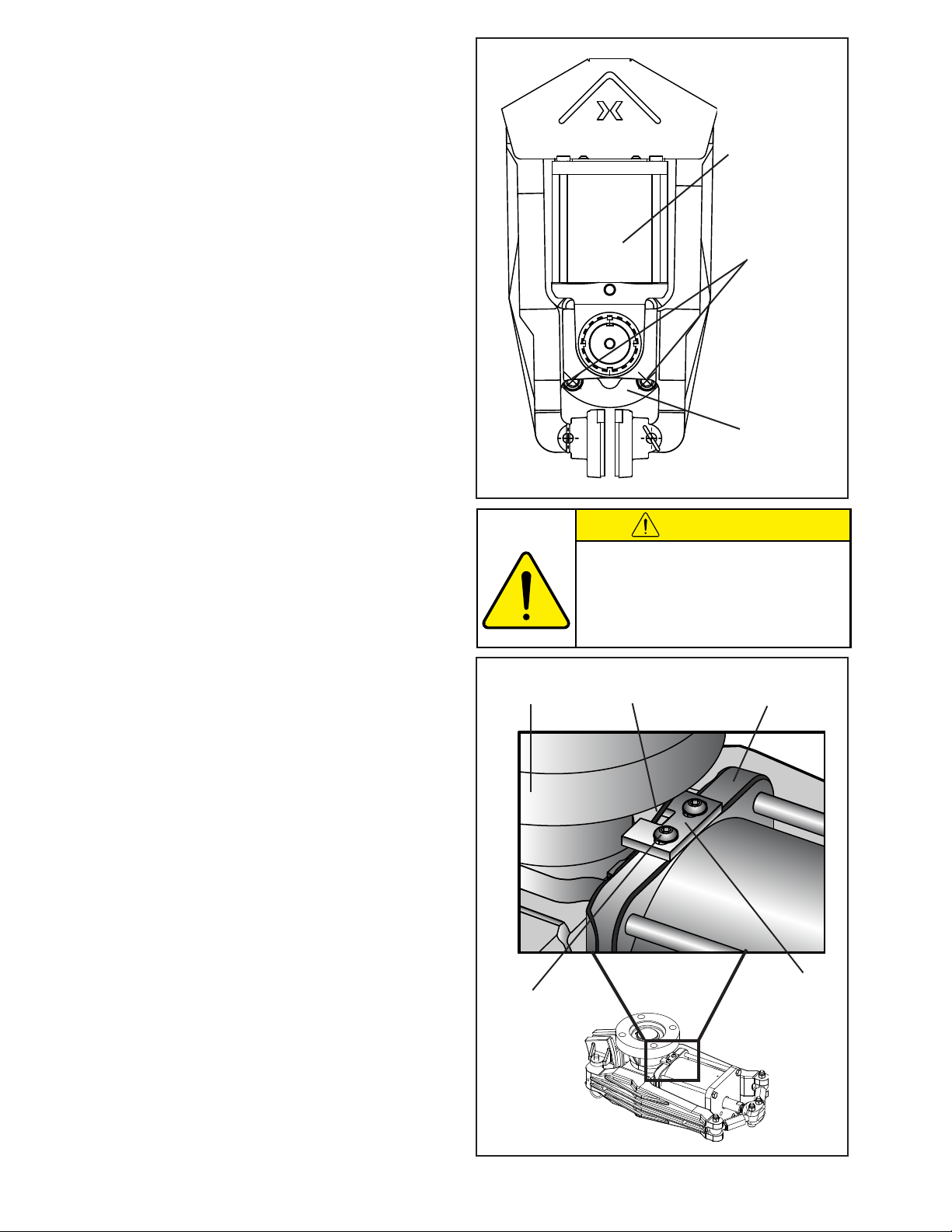
NOTE: The VC500 Spring Actuator Assembly is factory
calibrated to a 12.7 mm [0.500 in] wide brake disc. No
adjustment is necessary when mating a disc of this
size.
If using a thicker or thinner disc, offset shoes will be
required. Contact Nexen for available sizes. When
replacing with offset shoes, see the FRICTION FACING
ADJUSTMENT section to readjust for a wider or thinner
disc.
1. Release the brake with at least 4.1-4.8 bar [60-70
psi] air pressure.
2. Position the brake shoes on the disc and release the
air pressure to lock the brake in place.
NOTE: Brake shoes must be mounted with approximately
1.6 mm [1/16 inch] space between the outside edge of
the shoe and the outer diameter of the disc.
2. Align the frame on a support (customer supplied)
so the brake arms are parallel with the brake disc
and the brake shoes are positioned at least 1.6 mm
[1/16 inches] in from the disc edge.
NOTE: The support must be capable of sustaining loads
produced during braking.
Spring Actuator
Assembly
Cap Screws &
Lock Washers
(customer
supplied)
Frame
(Item 1)
Figure 3
If using shims under the Frame (Item 1): Do not to warp
the Frame when tightening the Cap Screws (customer
supplied).
Ve r t i c a l Mo u n t i n g on l y
NOTE: A special Bracket and Screw kit (Items 43 & 42)
is supplied with each VC500 unit to be used in vertical
mounting applications.
If mounting vertically, attach the Bracket before
proceeding with step three:
Secure the Bracket to the bottom of the Actuator
Mount (Item 4) with the supplied Screws. Position the
Bracket with the notch straddling the arm of the frame
to provide support (See Figure 4). Hold the Bracket
tightly to the frame, and tighten the Screws to create
a hard stop.
3. Release the VC500 from the disc.
4. Tighten the Cap Screws (customer supplied) and
the Lock Washers (Item 20) to 67.8 Nm [50 ft-lb]
torque (See Figure 3).
Frame
(Item 1)
Cap Screw
(Item 42)
The Cap Screws (Item 17) must sustain the
loads produced by the mounting torque.
The torque rating specified in Tables 1 & 2
allows a significant load safety factor. DO
NOT EXCEED TORQUE LIMITS SPECIFIED
FOR THE CAP SCREWS.
Frame Arm
Actuator Mount
(Item 4)
Bracket
(Item 43)
FORM NO. L-21156-F-0209
Figure 4
6
Page 7
DANGER
WARNING
FRICTION FACING ADJUSTMENT
Spacing as
described in
Step 8
WARNING
NOTE: The VC500 Spring Actuator Assembly is factory
calibrated to a 12.7 mm [0.500 in] wide brake disc. No
adjustment is necessary when mating to a disc of this
size. If using a thicker or thinner disc, offset shoes will
be required. Contact Nexen for available sizes.
Do not wear facings down within
0.762 mm [0.030 in] of the iron
facing shoe. Loss of clamping
force and machine damage will
result. Monitor facing wear closely
and replace before worn to this
dimension.
Adjustment of linkage is required for
any disc above or below 12.4 mm [0.500
in] thick. Loss of torque or failure of the
manual release function may result.
1. If the brake is mounted and clamping on the disc,
apply >4.1 bar (>60 psi) to release the spring
actuator force from the linkage. The brake must be
disengaged and unloaded for linkage adjustment
(See Warning note to the right).
NOTE: Brake shoes and detent pins must be installed
in order to perform the following procedure.
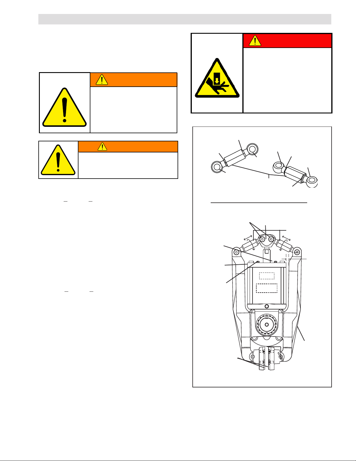
2. Remove the brake guard by removing cap screws
(Item 34) (See Figure 5).
3. Remove only the center rod ends (Item 17 & 16)
from the clevis (Item 14) by removing the locking
nuts (Item 18) and screws (Item 28).
4. Apply >4.1 bar (>60 psi) to the spring actuator.
Jam Nut (RH)
(Item 19)
Rod End (RH)
Linkage Assembly
Screw (Item 28) and
Lock Nut (Item 18)
Actuator
Face
Actuator Cap
(Item 10)
Cap Screws
(Item 34)
Do not allow air pressure to
drop during brake linkage
adjustment. High spring forces
and possible pinch points require
constant air pressure to prevent
operator injury. Always keep
hands and fingers out of the
linkage assembly area when
adjusting and actuating the brake.
Jam Nut (LH)
(Item 36)
Rod End (RH)
(Item 16)
Jam Nut (RH)
Rod End (LH)
(Item 17)
(Item 16)
Turnbuckle
(Item 23)
Clevis
(Item 14)
Jam Nut (LH)
(Item 36)
See Linkage
Assembly Above
(Item 19)
Rod End (LH)
(Item 17)
5. With the air pressure applied rotate the clevis (Item
14) until the rear end is 100.9 mm (3.97 in) away
from the face of the actuator.
6. Insert the center rod ends (Items 16 & 17) back
into the clevis (Item 14) and tighten the locking nuts
(Item 18) to 45.2 Nm (435 in-lb).
Once the rod ends are installed, retighten the clevis
jam nut (Item 19), apply servicable thread locker to
jam nut and torque to 4.5 Nm (40 in-lb).
7. Clevis adjustment is now complete.
8. It is critical that the linkage assemblies are both
equal length. To ensure this, adjust both linkages
by rotating the turnbuckle until the spacing between
the arm (Item 3) and the actuator cap (Item 10) is
equal -- see drawing for clarification. This will create
a starting point for the final facing adjustment.
7
Item 3
Friction Facings
(Item 6)
Figure 5
FORM NO. L-21156-F-0209
Page 8
WARNING
CAUTION
NOTE: DO NOT assume the thread lengths are equal
on the rod ends. Use the actuator cap as a reference
to equalize linkage length (as described in step 11).
9. With >4.1 bar (>60 psi) still applied, rotate the
turnbuckles (Item 23) equally until contact is made
between the facings (Item 6) and the brake disc.
Then, back off 1/4 turn on each turnbuckle.
NOTE: The gap between the brake arm (Item 3) and
the actuator cap (Item 10) should be equal on both
sides. If not, continue to adjust turnbuckles until both
arms are equally spaced and the facings (Item 6) are
in contact with the brake disc.
AIR CONNECTIONS
Pneumatically actuated devices require clean, pressure
regulated, and lubricated air for maximum performance
and long life. Your Nexen distributor carries filters,
regulators, and lubricators specifically designed to
operate with Nexen clutches, brakes, and valves.
Piping diagrams are included in this manual for a variety
of braking functions. Refer to OPERATIONAL MODES
for details.
10. Carefully re-tighten the jam nuts (Item 19 and 26)
to ensure that no turnbuckle movement is detected.
Apply serviceable thread lock and torque jam nuts
to 4.5 Nm (40 in-lb).
NOTE: LH jam nuts(Item 36) will have a paint mark to
identify them from the RH thread nuts.
11. Apply a serviceable thread lock to the cap screws
(Items 34) and reinstall the brake guard (Item 24).
Actuat o r is sp r i n g loaded
under extreme pressure. Do
not disassemble. If Actuator
malfunctions, replace or contact
Nexen. The turnbuckle assembly
can be used to physically release
the spring.
NOTE: The VC500 Caliper Brake has a .250–18 NPT
Do not use rigid pipe or tubing when
connecting directly to the Brake. Prevent
unshielded air hoses from rubbing on
metal surfaces or edges, as this will
cause rapid deterioration of the hose.
air inlet port. A .250–18 NPT (male) and .250 ISO
7/1 (female) adapter is provided for metric plumbing
applications.
LUBRICATION
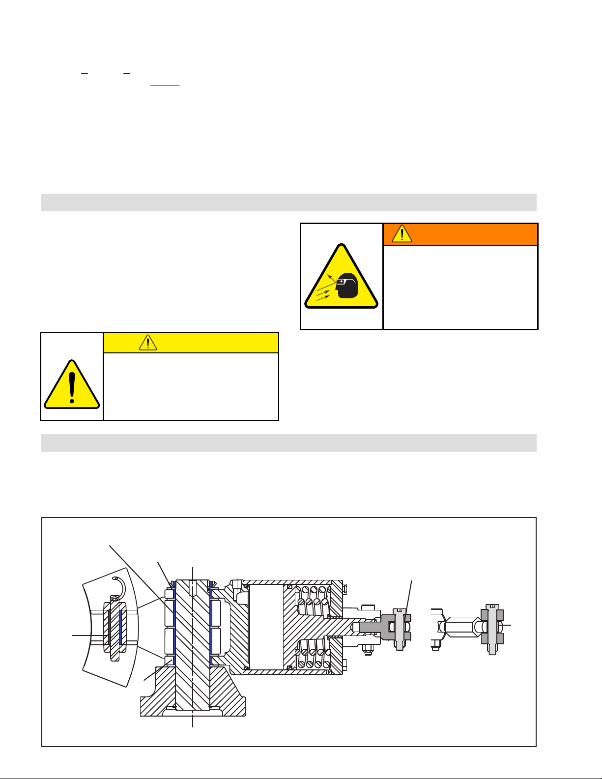
All pivot points on the VC500 Caliper Brake use self-lubricated high PV bearings.
For tension control applications where the disc is held at elevated temperatures for extended periods, use a light
machine oil on Bearings (Items 11, 12, 13, 22, 28, and 37) (See Figure 6).
11
13
28
37
22
FIGURE 6
FORM NO. L-21156-F-0209
12
8
Page 9
OPERATIONAL MODES
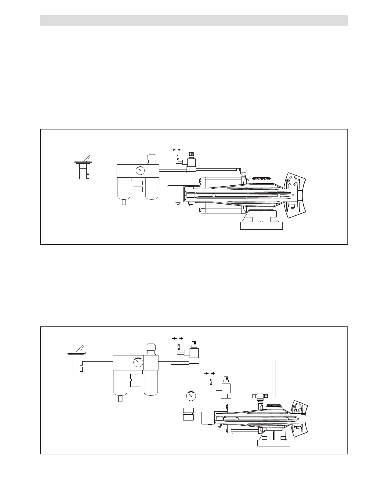
NORMAL SERVICE MODE
Below is a standard air brake control circuit. On-off air control is achieved by the 3-way valve. Torque is accomplished
by the regulation of air pressure.
NOTE: Maximum operating pressure is 8.3 bar [120 psi] (See Figure 6).
NORMAL SPRING ENGAGED MODE
This mode is for occasional duty, non-cyclic applications only. A hold-off pressure of 4.1-4.8 bar [60-70 psi] is used
to compress the spring inside the Actuator canister. A control signal is used to release the hold-off pressure, thus
applying full spring-engaged torque to the brake (See Figure 7).
Power
Source
Regulator
Air Supply
3-Way Manual
Control
Lubricator
Filter
3-Way Control N.C.
Figure 7
SPRING ENGAGED-DUAL AIR MODE
This mode allows the selection of any value of spring engaged torque (from zero to full scale) available with a particular
disc size by relieving a percentage of the minimum Hold-Off pressure 4.1 bar [60 psi]. The remaining pressure,
balanced against the spring force, reduces the output of the Actuator (See Figure 8).
EXAMPLE: A standard spring set brake with a 18 inch disc has a full rated spring engaged torque of 3,480 Nm
[30,800 in-lb] when using the minimum hold-off pressure of 4.1 bar [60 psi]. If it is desired to have 60% of this torque
or 2,016 Nm [18,000 in-lb], relieve the hold-off pressure 60 percent or 1.9 bar [36 psi], leaving 2.2 bar [24 psi] holdoff pressure.
Figure 8
Air Supply
3-Way Manual
Control
Regulator
Filter
Lubricator
Power Source
Regulator
3-Way Control N.C.
Power Source
9
3-Way Control
N.C.
FORM NO. L-21156-F-0209
Page 10
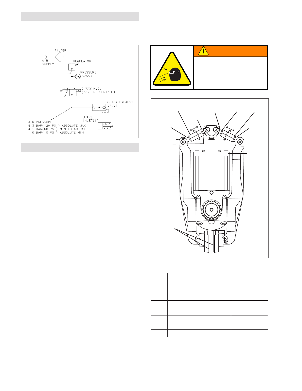
WARNING
AIR CONNECTIONS
All Nexen pneumatically actuated devices require clean
and dry air, which meet or exceeds ISO 8573.1: 2001
Class 4.4.3 quality.
Actuator is spring loaded
under extreme pressure. Do
not disassemble Actuator. If
Actuator malfunctions, replace
the Actuator or contact Nexen.
MAINTENANCE
MANUAL RELEASE
To m a n u a l l y r e l e a s e T h e b r a k e :
1. Remove brake guard (Item 24).
2. Using a thin 3/4" wrench, loosen the four jam nuts
(Item 19) on the rod ends (Items 16 & 17).
3. Using a 1" wrench, rotate the turnbuckles (Item 23)
equally until a noticeable gap is visible between the
facings (Item 6) and the brake disc.
NOTE: Nexen recommends rotating the turnbuckles 1/2
turn at a time on each side until the brake is completely
disengaged.
Turnbuckle
(Item 23)
Rod End
(Item 16)
Jam Nut
(Item 36, LH)
(Item 19)
Brake Arm
(Item 3)
Friction Facing
(Item 6)
Rod End
(Item 17)
Rod End
(Item 16)
Jam Nut
(Item 19)
(Item 36, LH)
Rod End
(Item 17)
Actuator
Cap
(Item 10)
Brake Arm
(Item 3)
To r e e n g a g e T h e b r a k e :
Follow instruction in friction facing adjustment
section.
GENERAL
1. Adhere to the following bolt tightening torques (See
Table 3).
2. Inspect Actuator exterior.
3. Check tightness of air line connections, and
condition of all air lines. Replace worn or damaged
air lines.
4. Inspect Friction Facings for wear. Replace before
contact is made between shoes and brake disc.
5. Lubricate items requiring lubrication (See
LUBRICATION).
FORM NO. L-21156-F-0209
Figure 9
TABLE 3
ITEM
DESCRIPTION TORQUE
No.
15 Machine Screw
(friction facing)
19 Jam Nuts (linkage) 20-27 [15-20]
18 Lock Nuts (linkage) 44-57 [33-42]
33 Lock Nut (post) finger tighten,
36 Jam Nuts-LH (linkage) 20-27 [15-20]
10
Nm [ft-lb]
12-16 [8-11]
then bend tab
Page 11
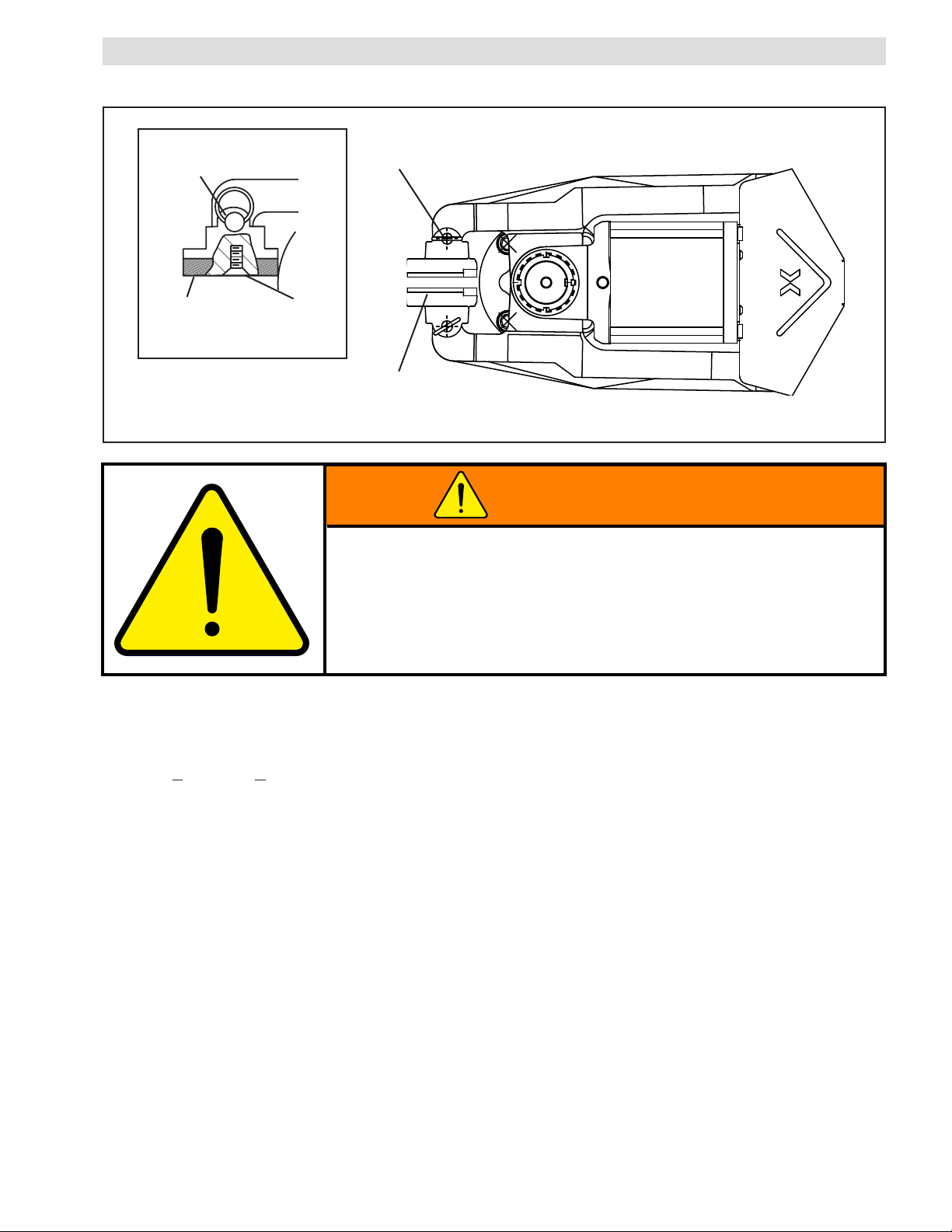
WARNING
PARTS REPLACEMENT
FRICTION FACINGS
Shoe
Pins
(Item 8)
Shoe
Pins
(Item 8)
Friction
Facing
(Item 6)
Figure 9
Machine
Screw
(Item 15)
Friction Facing
Shoe Assembly
(Items 5, 6, and 15)
Do not wear facings within 0.762 mm [0.030 in] of the iron facing shoe.
Loss of clamping torque and machine damage will result. Monitor facing
wear closely and replace before worn to this dimension.
Adjustment of linkage is required for any disc above or below 12.4 mm
[0.500 in] thick. Loss of torque or failure of the manual release function
may result.
NOTE: When replacing Friction Facings, inspect the Friction Disc for scoring or grooves. If necessary, the Friction
Disc may be machined. A maximum of 0.76 mm [0.030 in] may be removed from each side of the Friction Disc
before it is necessary to replace the Friction Disc.
1. Apply >4.1 bar [m >60 psi] to open shoes
or manually release the brake (See MANUAL
RELEASE section for details).
2. Remove the shoe pins (Item 8).
3. Remove the friction facing shoe assembly (Items 5,
6, and 15).
NOTE: The Machine Screws are assembled with an
anaerobic locking compound. To loosen the compound,
insert a properly fitting screwdriver into the head of
the Machine Screw and strike the screwdriver with a
hammer. Never use an impact wrench to remove the
Machine Screws.
4. Remove the old Machine Screws (Item 15) and old
Friction Facings (Item 6).
5. Using new Machine Screws (Item 15), install new
Friction Facings (Item 6) (See Figure 12).
6. Tighten the new Machine Screws (Item 15) to 1216 Nm [8-11 ft-lb] torque.
7. Reinstall the Friction Facing Shoe Assembly (Items
5, 6, and 15) and Shoe Pins (Item 8).
8. Perform Friction Facing clearance adjustment (See
FRICTION FACING ADJUSTMENT section for
details).
11
FORM NO. L-21156-F-0209
Page 12
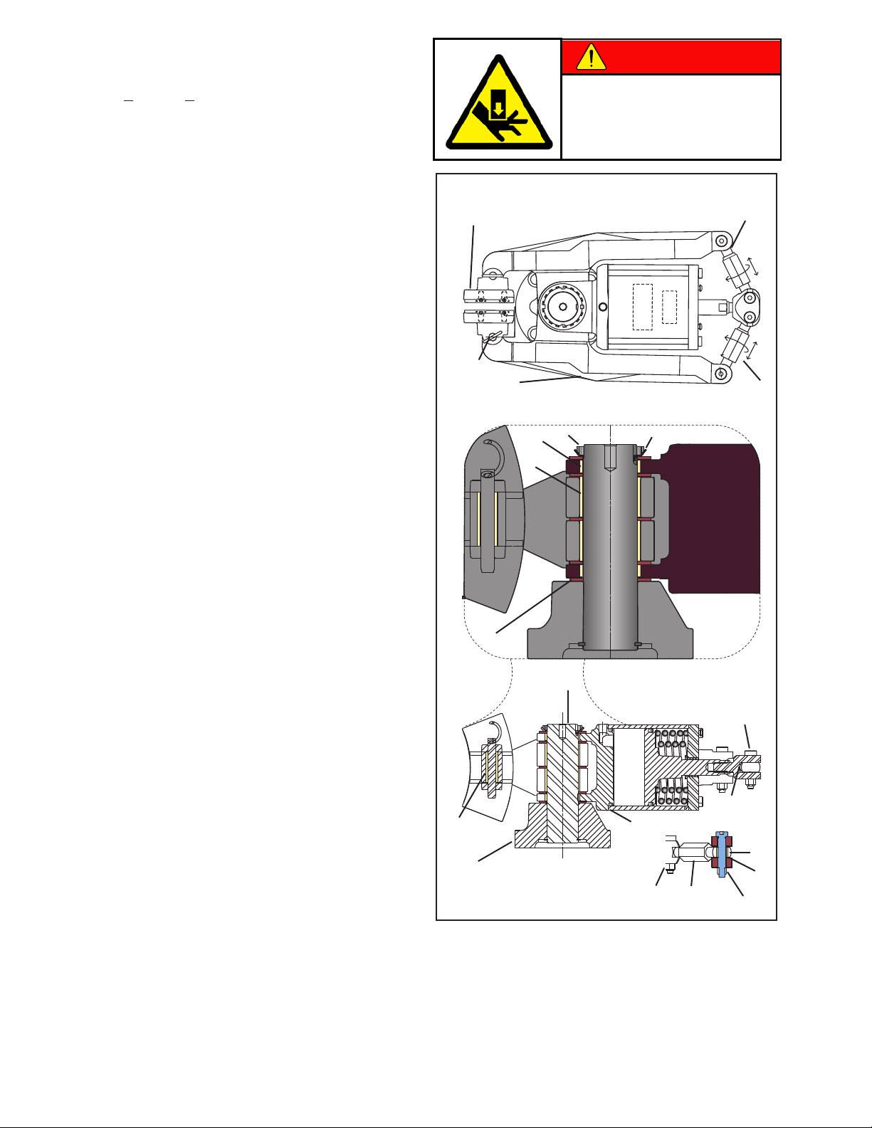
DANGER
BEARINGS
1. Remove Brake Guard (Item 24).
2. Apply >4.1 bar (>60 psi) to open shoes or manually
release the brake (See MANUAL RELEASE
section).
3. Remove shoe pins (Item 8).
Due to high spring forces and
possible pinch points, always keep
hands and fingers out of the linkage
assembly area when adjusting and
actuating the brake.
4. Remove the friction facing shoe assembly (Item 5, 6,
and 15).
5. Remove air pressure from the brake.
NOTE: Nexen recommends removing the entire caliper
brake assembly from the machine at this time.
6. Open the tab (Item 35) and remove the lock nut
(Item 33).
NOTE: Mark the rod ends (Item 16 & 17) and turnbuckle
assemblies (Item 23) to designate right and left side
assemblies of the brake. Mark each assembly to
designate arm (Item 3) and clevis side (Item 14).
7. Remove the rod ends (Item 16 & 17) from the clevis
(Item 14) and the arm (Item 3) by removing the
locking nuts (Item 18).
NOTE: Do not adjust the rod and turnbuckle assemblies
while removed from the clevis.
8. Roll the caliper assembly on its side (or up-sidedown) and pull the pin/base (Items 1 & 2) assembly
out of the arms and actuator mount (Item 4).
9. Apply hand force to the arms (Item 3) to pry them
out of the actuator mount.
Friction Facing
Shoe Assembly
(Items 5, 6, and 15)
8
3
13
11
16
17
33 35
10. Collect and inspect thrust bearings (Item 12 & 20).
Replace if necessary.
11. Press the old bearings (11, 13, 22, & 37) out of the
arms (Item 3) and rod ends (Items 16 & 17).
12. Press new bearings (Items 11, 13, 22, & 37) into
the arms (Item 3) and rod ends (Items 16 & 17).
13. Still in the inverted position, reassemble the arm,
bearing, and actuator mount assembly, carefully
aligning the thrust bearings.
14. Slip the bottom thrust bearing on the pin/base
assembly and insert the pin into the arm/actuator
mount assembly.
15. Install final the thrust bearing, locking washer (Item
35), and lock nut (Item 33).
16. Finger tighten (Item 33) and bend the tab up on the
lock washer to hold the lock nut in place.
17. Reinstall marked rod ends (Items 16 & 17) and
turnbuckle assemblies (Item 23) to the proper sides
of the brake.
18. Reinstall the caliper brake onto the machine and
follow instructions in the FRICTION FACING
ADJUSTMENT section to ensure proper operation.
12
37
1
Figure 10
2
28
14
4
22
18
23
20
18
FORM NO. L-21156-F-0209
12
Page 13
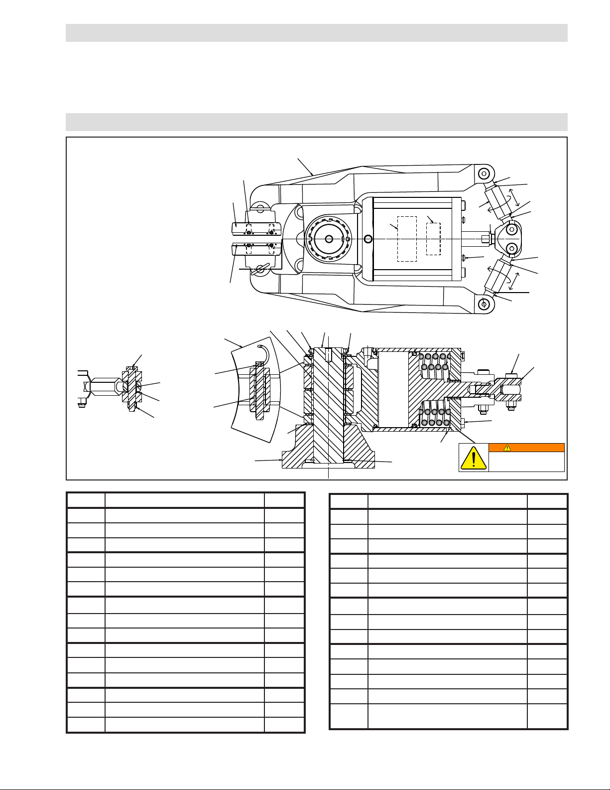
30
22
20
18
37
8
5
1
12
25
Point drain
hole down
26
14
28
35
2
33
13
11
17
34
19
16
17
23
16
39
38
3
15
5
6
19
36
36
19
WARNING
REPLACEMENT PARTS
The Item or balloon number for all Nexen products is used for part identification on all product parts lists, product price
lists, unit assembly drawings, bills of materials, and instruction manuals.
When ordering replacement parts, specify model designation, item number, part description, and quantity. Purchase
replacement parts through your local Nexen Distributor.
PARTS LIST
Actuator is spring loaded
under extreme pressure. Do
not disassemble.
FORM NO. L-21156-F-0209
ITEM DESCRIPTION QTY
20 Thrust Washer 4
22 Sleeve Bearing 4
23 Turnbuckle 2
24 Guard 1
25 Retaining Ring 1
26 Hex Head Screw 4
28 Shoulder Screw 2
30 Shoulder Screw 2
33 Bearing Lock Nut 1
34 Cap Screw 2
35 Keyed Washer 1
36 Jam Nut (Left-Hand) 2
37 Sleeve Bearing 4
Air Inlet Adapter, ¼ NPT,
metric (not shown)
13
41
Figure 11
ITEM DESCRIPTION QTY
1 Pivot Pin Frame 1
2 Arm Pivot Pin 1
3 Brake Arm 2
5 Brake Shoe 2
6 Friction Facing 2
8 Detent Pin 2
11 Sleeve Bearing 2
12 Thrust Bearing 5
13 Sleeve Bearing (Actuator) 2
14 Clevis 1
15 Cap Screw 8
16 Solid Rod End (Right-Hand) 2
17 Solid Rod End (Left-Hand) 2
18 Hex Nut 18
19 Jam Nut 3
NOTE: The VC500 Caliper Brake has a .250–18 NPT air inlet port. A .250–18 NPT (male) and .250 ISO 7/1 (female) adapter is provided for
metric plumbing applications.
1
Page 14

WARRANTY
Nexen Group, Inc.
560 Oak Grove Parkway
Vadnais Heights, MN 55127
800.843.7445
Fax: 651.286.1099
www.nexengroup.com
ISO 9001 Certified
Warranties
Nexen warrants that the Products will be free from any defects in material or workmanship for a period of 12 months
from the date of shipment. NEXEN MAKES NO OTHER WARRANTY, EXPRESS OR IMPLIED, AND ALL IMPLIED
WARRANTIES, INCLUDING WITHOUT LIMITATION, IMPLIED WARRANTIES OF MERCHANTABILITY AND
FITNESS FOR A PARTICULAR PURPOSE ARE HEREBY DISCLAIMED. This warranty applies only if (a) the
Product has been installed, used and maintained in accordance with any applicable Nexen installation or maintenance
manual for the Product; (b) the alleged defect is not attributable to normal wear and tear; (c) the Product has not been
altered, misused or used for purposes other than those for which it was intended; and (d) Buyer has given written
notice of the alleged defect to Nexen, and delivered the allegedly defective Product to Nexen, within one year of the
date of shipment.
Exclusive Remedy
The exclusive remedy of the Buyer for any breach of the warranties set out above will be, at the sole discretion of
Nexen, a repair or replacement with new, serviceably used or reconditioned Product, or issuance of credit in the
amount of the purchase price paid to Nexen by the Buyer for the Products.
Limitation of Nexen’s Liability
TO THE EXTENT PERMITTED BY LAW NEXEN SHALL HAVE NO LIABILITY TO BUYER OR ANY OTHER
PERSON FOR INCIDENTAL DAMAGES, SPECIAL DAMAGES, CONSEQUENTIAL DAMAGES OR OTHER
DAMAGES OF ANY KIND OR NATURE WHATSOEVER, WHETHER ARISING OUT OF BREACH OF WARRANTY
OR OTHER BREACH OF CONTRACT, NEGLIGENCE OR OTHER TORT, OR OTHERWISE, EVEN IF NEXEN
SHALL HAVE BEEN ADVISED OF THE POSSIBILITY OR LIKELIHOOD OF SUCH POTENTIAL LOSS OR
DAMAGE. For all of the purposes hereof, the term “consequential damages” shall include lost profits, penalties, delay
images, liquidated damages or other damages and liabilities which Buyer shall be obligated to pay or which Buyer may
incur based upon, related to or arising out of its contracts with its customers or other third parties. In no event shall
Nexen be liable for any amount of damages in excess of amounts paid by Buyer for Products or services as to which
a breach of contract has been determined to exist. The parties expressly agree that the price for the Products and the
services was determined in consideration of the limitation on damages set forth herein and such limitation has been
specifically bargained for and constitutes an agreed allocation of risk which shall survive the determination of any court
of competent jurisdiction that any remedy herein fails of its essential purpose.
Limitation of Damages
In no event shall Nexen be liable for any consequential, indirect, incidental, or special damages of any nature
whatsoever, including without limitation, lost profits arising from the sale or use of the Products.
Warranty Claim Procedures
To make a claim under this warranty, the claimant must give written notice of the alleged defect to whom the Product
was purchased from and deliver the Product to same within one year of the date on which the alleged defect first
became apparent.
FORM NO. L-21156-F-0209
14
 Loading...