

Page 1
WEB CONTROL PRODUCTS
User Manual
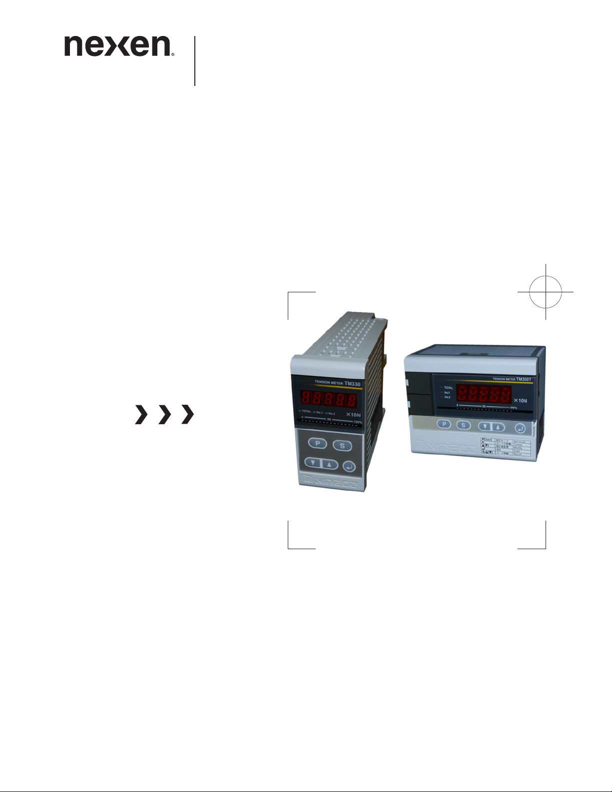
Tension Meter
TM310T & TM340
FORM NO. L-21279-B-0513
i
FORM NO. L21279-B-0513
Page 2
In accordance with Nexen’s established policy of constant product improvement, the specifications contained in this manual
are subject to change without notice. Technical data listed in this manual are based on the latest information available at
the time of printing and are also subject to change without notice.
Technical Support: 800-843-7445
(651) 484-5900
www.nexengroup.com
DANGER
Read this manual carefully before installation and operation.
Follow Nexen’s instructions and integrate this unit into your
system with care. This unit should be installed, operated and
maintained by qualified personnel ONLY. Improper installation
can damage your system, cause injury or death. Comply with
all applicable codes.
This document is the original, non-translated, version.
Copyright 2013 Nexen Group, Inc.
FORM NO. L21279-B-0513
Nexen Group, Inc.
560 Oak Grove Parkway
Vadnais Heights, Minnesota 55127
ISO 9001 Certified
ii
Page 3

TABLE OF CONTENTS
1. INTRODUCTION ............................................................................................................................................................................................. 1
2. UNIT LAYOUT ............................................................................................................................................................................................. 2
3. INSTALLATION
3.1 Physical Mounting ...................................................................................................................................................................... 3
3.1.1 TM310T Mounting ............................................................................................................................................. 3
3.1.2 TM340 Mounting ......................................................................................................................................... 3
3.2 Dimensions .......................................................................................................................................................................... 4
3.3 Wiring Installation Guidelines .......................................................................................................................................................................... 5
3.4 Electrical Connections ...................................................................................................................................................................... 6
3.5 Input / Output Descriptions.......................................................................................................................................................................... 7
4. FRONT PANEL OPERATION .................................................................................................................................................. 7
5. PARAMETER SETUP
5.1 Navigating Setup Mode ..................................................................................................................................................................................... 8
5.2 Initial Setup ..................................................................................................................................................................................... 8
5.3 Calibration ........................................................................................................................................................... 8
5.4 Parameter List ......................................................................................................................................................... 10
5.5 Parameter Descriptions ......................................................................................................................................................... 10
6. TROUBLESHOOTING
6.1 Tension Display Errors .................................................................................................................................................... 12
6.2 Tare / Span Adjustment Error Codes .............................................................................................................................................................. 12
6.3 Output Testing Function ..................................................................................................................................................................... 12
6.4 Sensor Measurement Diagnostics ............................................................................................................................................................... 13
7. MAINTENANCE ................................................................................................................................................................................................. 14
8. SPECIFICATIONS ................................................................................................................................................................................................ 14
9. WARRANTY ............................................................................................................................................................................................................ 15
iii
FORM NO. L21279-B-0513
Page 4
1. INTRODUCTION
S
0
50
100%
10N
TOTAL
NO.1
NO.2
TENSIO N M
ETER
TM310T
P(3sec)
Setup mo de
Set mode
S
Cu
rsor mo
vem
ent
Cursor
(
)
Par
ameter a mendment
Modify
Set
Enter
S+
(
)
Mode m
o
vement
Recall
P
The Nexen TM310T/TM340 Tension Meters are designed
for web tension systems that utilize load cell based tension
sensors to measure tension and provide amplified signals
for control with auxiliary equipment and recording.
The TM310T/TM340 Tension Meter series provides
measurement display and amplification for low output
voltage tension sensors used in web processing equipment
for materials such as paper, film, textile, and rubber. The
Tension Meter features an internal calibration system to
simplify the calibration procedure and does not require the
adjustment of potentiometers or use of a multimeter in the
calibration procedure.
The TM310T/TM340 Tension Meters display the measured
tension on a five digit display. In addition to the front panel
reading, the Tension Meter provides a selectable voltage
or current control output for use with external equipment,
independent and summed tension signals for monitoring,
DC relay contacts for tension alarms, and RS-485 serial
output for monitoring.
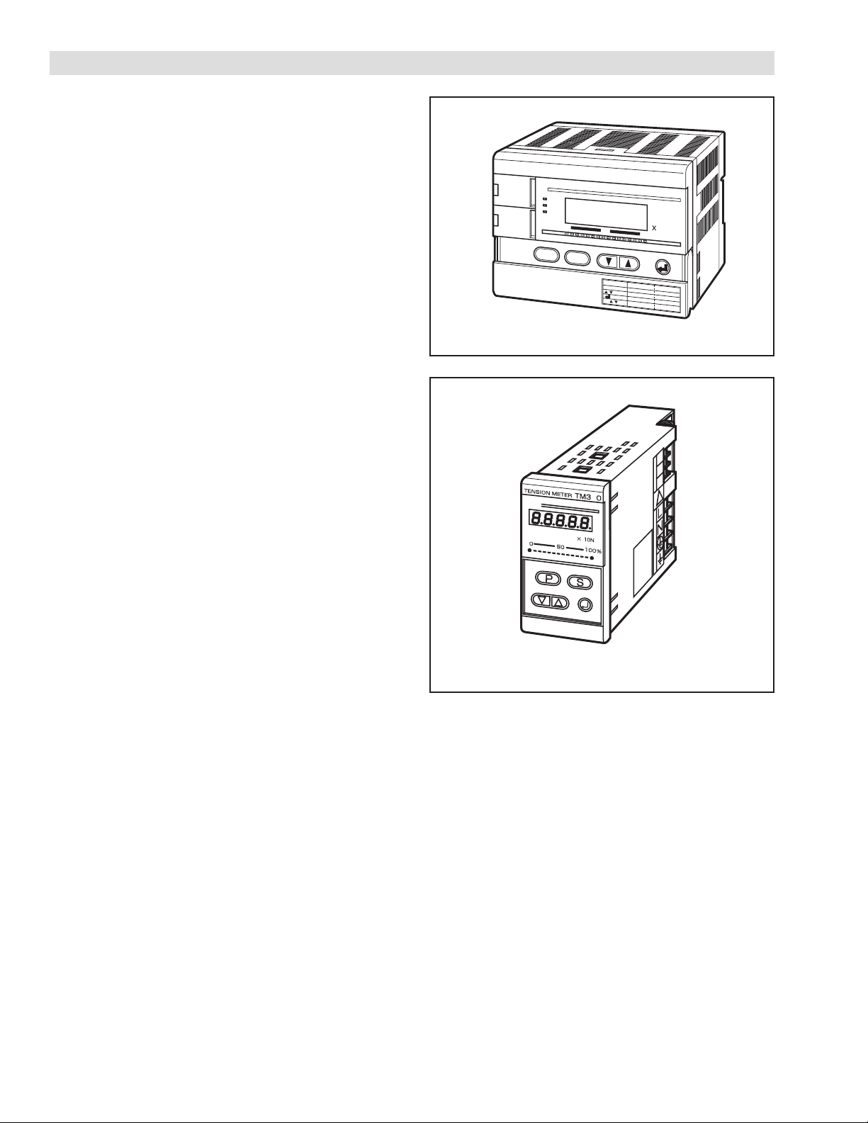
TM310T
The TM310T Tension Meter is the DIN Rail mount version
of the Tension Meter family.
TM340
The TM340 Tension Meter is the Panel Mount version of
the Tension Meter family.
TOTAL
NO.1
NO.2
P
FIGURE 1.1 TM310T
TENSIO N M
ETER
TM310T
0
50
100%
10N
S
P(3sec)
Setup mo de
S
(
S+
4
Set mode
Cu
rsor mo
vem
ent
)
Cursor
Par
ameter am endment
Modify
Set
(
Enter
)
Mode m
o
vement
Recall
FORM NO. L21279-B-0513
FIGURE 1.2 TM340
1
Page 5
2. UNIT LAYOUT
5
6
FRONT PANEL
2
TENSION MET ER
TOTAL
NO.1
NO.2
P
1
0 100%50
S
5
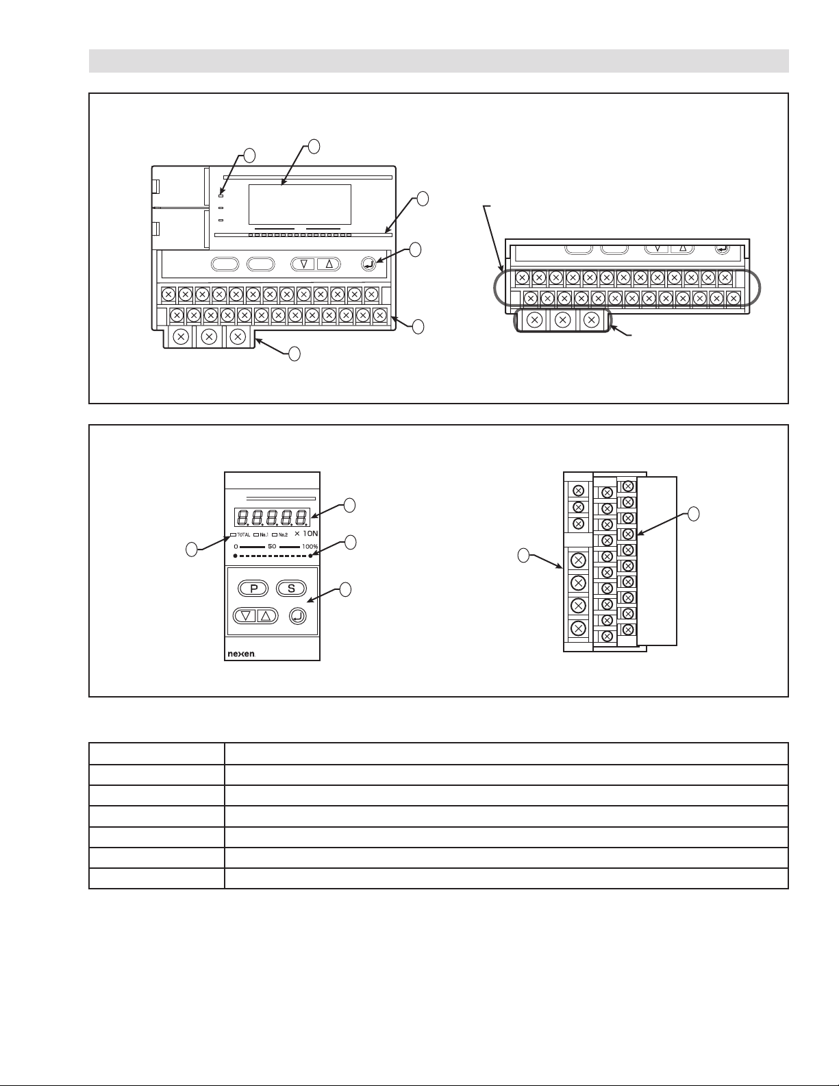
FIGURE 2.1 TM310T Unit Description
FRONT PANEL
TENSION M ETER
TM340
TM310T
×10N
2
TERMINAL BLOCK DESCRIPTION
3
4
6
Signal Terminals
(M3.5 screws)
S
P
Power Terminals
(M4 screws)
BACK
6
1
FIGURE 2.2 TM340 Unit Description
Function
1
2
3
4
5
6
No. 1 / No. 2 / TOTAL Display LEDs
5-digit Tension Value Display Screen
Tension Indicator Graph
Control Keys
Power Terminal Block
Signal Terminal Block
3
5
4
2
FORM NO. L21279-B-0513
Page 6
3. INSTALLATION
3.1 PHYSICAL MOUNTING
Never install the tension meter in the following locations:
• Locations subject to direct sunlight
• Locations subject to being splashed with water
• Locations with high humidity
• Locations subject to violent vibrations
• Locations containing corrosive atmospheres
• Locations with excessive dust
DIN Rail
3.1.1 TM310T Mou nTing
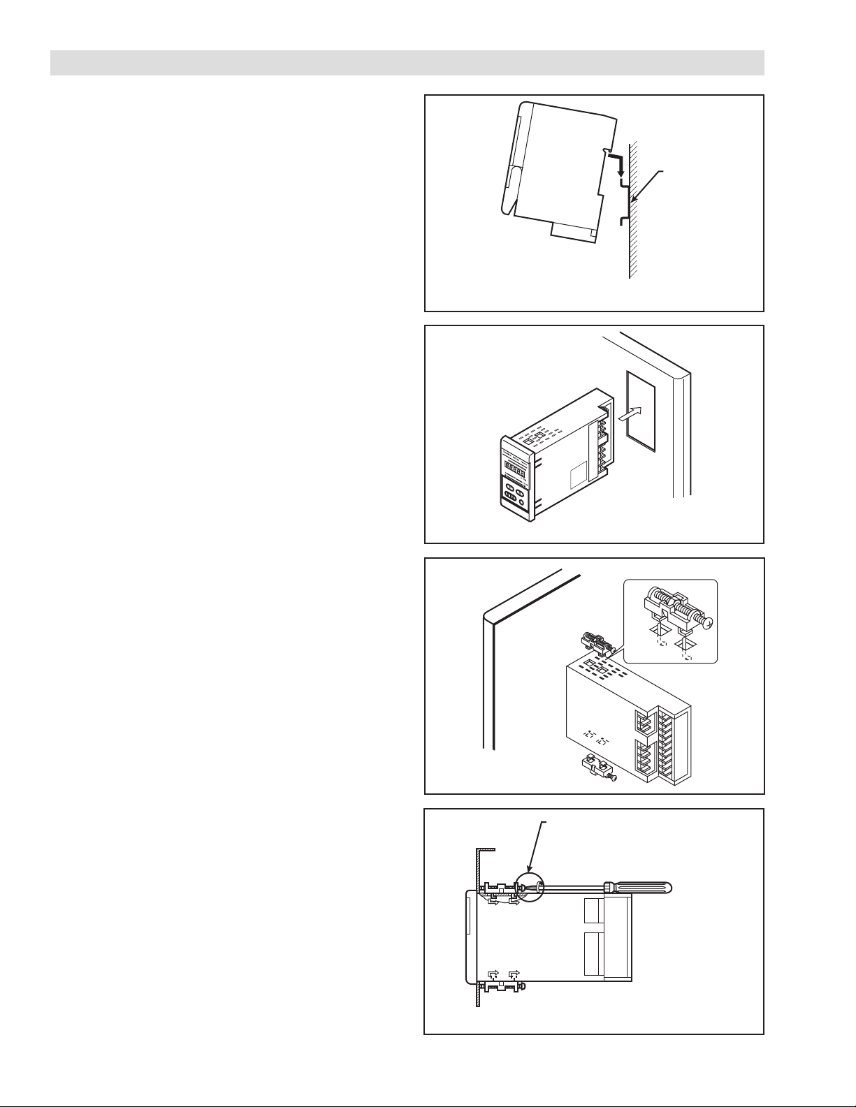
The TM310T Tension Meter is mounted on a DIN rail.
To attach the TM340 to the DIN rail:
Place the back clip of the unit above the rail as shown in
Figure 3.1, and slide the unit onto the rail with moderate
pressure so that the unit snaps into place.
To remove the unit from the din rail:
Pull the bottom tab locking the unit onto the Rail while lifting
the unit up and lightly pulling to remove from the rail.
3.1.2 TM340 MounTing
The TM340 is mounted in a panel and held in place by
included mounting screws.
1. Place the TM340 into the opening on the panel prepared
for the TM340 using the cutaway dimensions as
specified in the dimensional drawings in Section 3.2.
(See Figure 3.2)
2. Place the screw inside the screw mounting brackets
and slide the screw mounting brackets securely into
the TM340. (See Figure 3.3)
FIGURE 3.1
ATTACHING THE TM310T TO DIN RAIL
FIGURE 3.2
3. Using a screw driver, tighten the mounting screws on
the top and bottom of the unit. (See Figure 3.4.)
FORM NO. L21279-B-0513
FIGURE 3.3
Turn the screw until the end
makes contact with the panel
and then tighten the screw a
half-turn farther. (Reference
Torque: Approx. 0.4 Nm or less.)
FIGURE 3.4
3
Page 7
3. INSTALLATION (continued...)
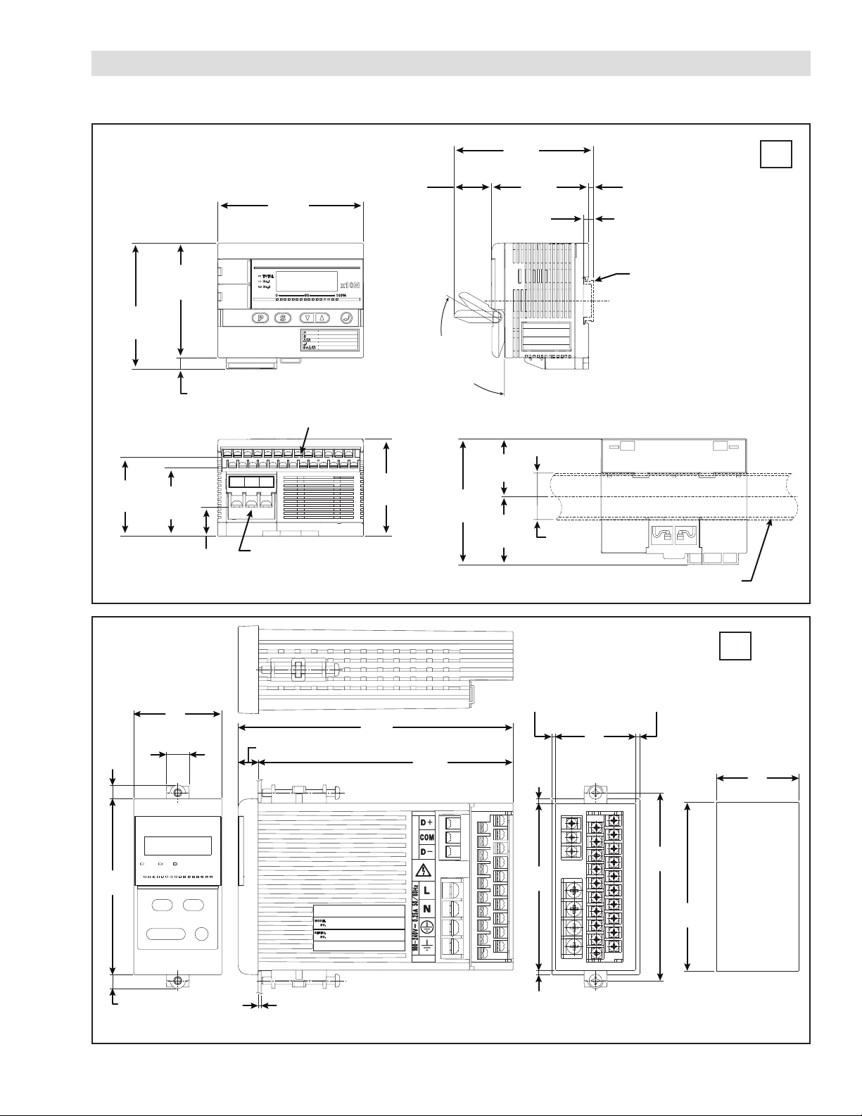
3.2 DIMENSIONS
NOTE: The illustration shows attachment to a
DIN rail with a width of 35 mm [1.38 in] and
depth of 7.5 mm [0.30 in] for reference purposes.
110
[4.33]
TENSION METER
TM310T
86.5
[3.41]
95
Parameter setting mode
[3.74]
(2sec)
Figure movement
Set point change
Enter
Setting cord movement
8.5
[0.33]
Signal Terminal M3
22
L N FG
Signal Terminal M4
60
[2.36]
52
[2.05]
[0.87]
FIGURE 3.7 TM310T DIMENSIONS
73.5
[2.89]
29
[1.14]
120
[3.74]
°
max
95
106
[4.17]
73.5
[2.89]
3.5
[0.14]
7. 5
[0.30]
DIN Rail (35mm in width)
BACK VIEW
43.5
[1.71]
51.5
[2.03]
35
[1.38]
DIN Rail: 35mm in width [1.38 inches]
mm
in
48
[1.89]
11
8
[0.31]
96
[3.78]
13
[0.51]
8
[0.31]
[0.43]
Thickness of the panel = Max. 5mm [0.02 in]
FIGURE 3.8 TM340 DIMENSIONS
150
[5.91]
139
[5.47]
RS485
2
[0.08]
2.5
[0.10]
91
[3.58]
2.5
[0.10]
44
[1.73]
2
[0.08]
102.4
[4.03]
+0.5
0
92
[3.62]
Panel cutting dimensions
mm
in
45
[1.77]
+0.5
0
4
FORM NO. L21279-B-0513
Page 8
3. INSTALLATION (continued...)
3.3 WIRING INSTALLATION GUIDELINES
This product is designed to minimize the effects of ElectroMagnetic Interference (EMI) on its operation, but as
with any electronic device, proper installation and wiring methods are necessary to ensure proper operation. By
doing so, the interference from external effects such as electrical line spikes, electrical noise, static electricity, etc.
will be minimized. The following methods outline wiring installation guidelines to protect your system:
• All input and output signal and sensor cables must be
shielded with the shields tied to earth ground at one end.
In case of very high frequency (MHz range) electrical
noise, both ends of the shield need to be tied to earth
ground.
Relay
• Keep cable length and unshielded leads as short as
possible. Think of them as antennae for noise.
R
• Use power line lters to suppress interference on the
AC voltage lines that power the unit.
Snubber
C
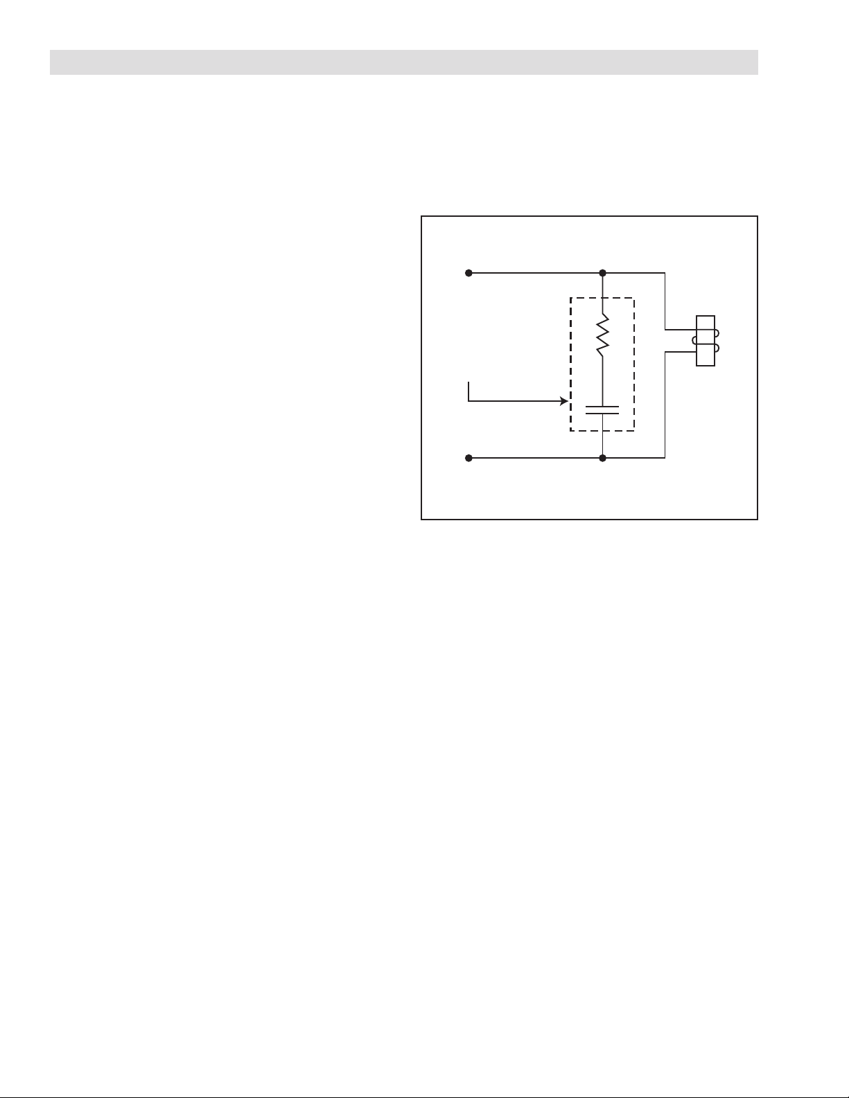
• Place a resistor-capacitor network (snubber) across
inductive coils such as relays and solenoids in order to
stop electrical interference at the source (See Figure
2).
• Isolate signal and sensor cables from cables carrying
AC voltages, power for high current loads or relays
and solenoids. Either relocate the signal and sensor
cables away from other cables or use grounded metal
conduits to shield them. This will reduce the potential
for noise interference between the signal and sensor
cables and the other noisy cables.
For environments that experience high levels of static electricity follow these additional guidelines:
• Remove the static charge from material carrying it. In
the case of webs that carry static charges, there are
static charge removal products available such as static
bars and ionized blowers.
Figure 3.9
Snubber applied across relay coil
• Ensure that sensors and machine frames are grounded
to earth through a low impedance path.
• Wrap grounding tinsel around sensors and cables that
are close to the source of the static electricity and
ground the tinsel to earth.
• Tie all signal and sensor cable shields directly to earth
ground without passing through the electronic device.
This will help prevent high voltage interference from
coupling into other circuits within the device.
FORM NO. L21279-B-0513
5
Page 9
3. INSTALLATION (continued...)
3.4 ELECTRICAL CONNECTIONS
Two TSA Sensors Two MB Sensors
Green
1
Black
2
Red
TSA
TSA
sensor
sensor
3
White
4
9
Green
5
Black
6
Red
7
White
8
9
10
11 11
One TSA Sensor
Green
1
Black
2
Red
TSA
sensor
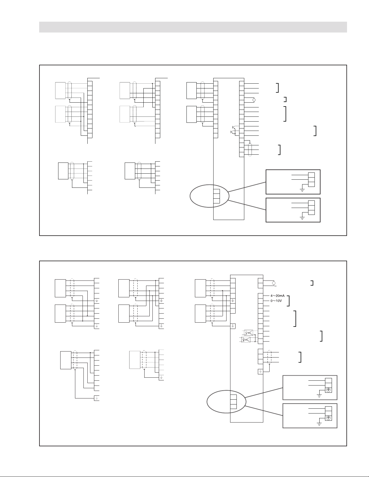
Terminals marked with an asterisk (*) cannot be
*
used in combination. Do not connect anything
White
10
11
5
9
Two SW Sensors
White
Red
SW
sensor
Black
White
Black
SW
sensor
Red
One MB Sensor
Green
†
White
Red
MB
sensor
Black
1
2
3
4
9
5
6
7
8
9
10
1
2
3
4
5
9
to the terminals that are not being used.
†
Wire color may be white or yellow.
FIGURE 3.10 TM310T Wiring Diagram
MB
sensor
MB
sensor
Connection
Power
Green
White
Red
Black
Green
White
Red
Black
1
†
2
3
4
9
5
†
6
7
8
9
10
11
12
13
14
15
16
17
18
19
20
21
22
23
9
24
25
26
4~20mA*
0~10V*
COM
+
0~1mA
A
(user supplied)
No.1 0~5V
No.2 0~5V
TOTAL 0~10V
COM
Minimum alarm
Maximum or unbalanced load alarm
Alarm Common
RS485 (+D)
COM
RS485(-D)
TM310T-DC
Control
Output
RS485
Communication
24VDC
GND
Indicator
Output
Meter
Output
+24V
0V
FG
Alarm
Output
D-type earth
TM310T-AC
100~240VAC
50/60Hz
L
N
FG
D-type earth
(Components supplied by the user)
Two TSA Sensors Two MB Sensors
Green
Black
Red
TSA
sensor
White
Green
Black
Red
TSA
sensor
White
One TSA Sensor
Green
Black
Red
TSA
sensor
White
Terminals marked with an asterisk (*) cannot be
*
used in combination. Do not connect anything
1
2
3 3
4
5
6
7
8
1
2
3
4
5
6
7
8
Two SW Sensors
White
SW
Red
sensor
Black
White
Black
SW
sensor
Red
One MB Sensor
Green
†
White
Red
MB
sensor
Black
1
2
4
5
6
1
2
3
4
5
to the terminals that are not being used.
†
Wire color may be white or yellow.
FIGURE 3.11 TM340 Wiring Diagram
MB
MB
sensor
sensor
Green
†
White
Red
Black
Green
†
White
Red
Black
Power
Connection
+
1
2
3
4
5
6
9
10
11
12
13
14
15
16
17
18
19
20
D+
COM
D—
0〜1mA
A
(supplied by the user)
*
Control
*
COM
Output
No.1 0〜5V
No.2 0〜5V
TOTAL 0〜10V
COM
Minimum alarm
Maximum or unbalanced load alarm
Alarm Common
RS485(D+)
COM
RS485(D-)
TM340-DC
Meter
Output
RS485
Communication
24VDC
GND
Indicator
Output
Alarm
Output
+24V
0V
earth
TM340-AC
100~240VAC
50/60Hz
L
N
earth
(Components supplied by the user)
6
FORM NO. L21279-B-0513
Page 10
3. INSTALLATION (continued...)
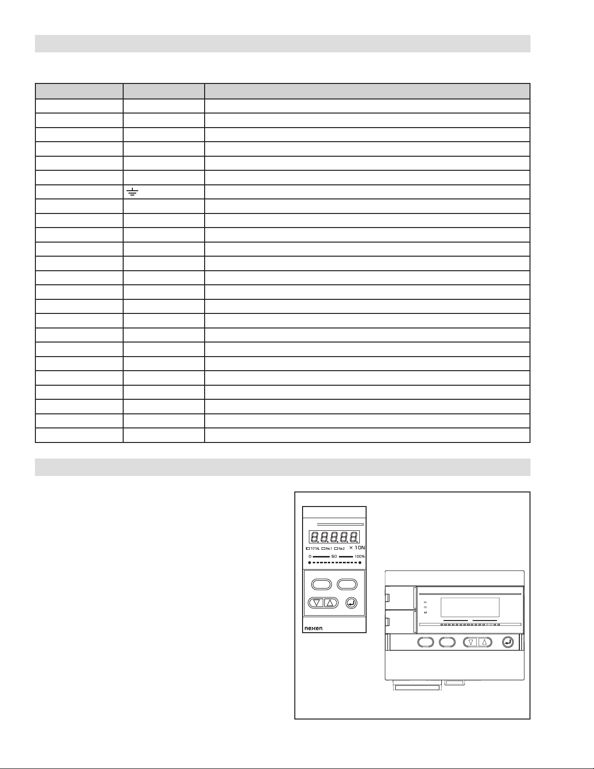
3.5 INPUT / OUTPUT DESCRIPTIONS
TM310T Terminal TM340 Terminal Function
1 1 No. 1 (+) Sensor Signal Input
2 2 No. 1 (–) Sensor Signal Input
5 5 No. 2 (+) Sensor Signal Input
6 6 No. 2 (–) Sensor Signal Input
3, 7 3 Sensor Excitation +6V
4, 8 4 Sensor Excitation COM
9 Shield
10 7 Sensor Excitation +15V
11 8 Sensor Excitation –15V
12 11 4 to 20mA Control Output
13 12 0 to 5V or 0 to 10V Control Output
14 13 Control Output COM
15 9 0 to 1mA Indicator Output
16 10 Indicator Output COM
17 14 0 to 5V No. 1 Sensor Tension Meter Output
18 15 0 to 5V No. 2 Sensor Tension Meter Output
19 16 0 to 10V Total Tension Meter Output
20 17 Meter Output COM
21 18 Minimum Tension Alarm Output
22 19 Maximum Tension or Unbalanced Load Alarm Output
23 20 Alarm Common
24 D+ RS485 (D+)
25 COM RS485 COM
26 D- RS485 (D–)
4. FRONT PANEL OPERATION
Tension Display
During normal operation, the tension meter displays the
tension measurement. The current measurement displayed
is indicated by the Total / No. 1 / No. 2 indicator light.
Pressing the S button cycles between displaying the total
tension measurement and the tension measurement on the
No. 1 or the No. 2 sensor.
Alarm Display
When the tension measurement exceeds the threshold of
an alarm trigger, the display will alternate between tension
measurement and one of the following alarm messages:
"HI":
“LO”:
“Un.b”:
FORM NO. L21279-B-0513
The alarm signal is output when the tension value exceeds
the limit set for maximum tension.
The alarm signal is output when the tension value is
below the limit set for minimum tension.
The alarm signal is output when the tension difference
between the No. 1 and No. 2 tension values exceed
the set limit.
TENSION M ETER
TM340
TM310T FRONT PANEL
S
TM340
FRONT
PANEL
Figure 4.1 View of Front Panels
7
TOTAL
No.1
No.2
0
PPS
TENSION METE R
50
100%
TM310T
x10N
Page 11
5. PARAMETER SETUP
5.1 NAVIGATING SETUP MODE
The tension meter is setup using parameters described in Section 5.4. To enter setup mode, press and hold the P button
until the display changes to read 0 in the first column.
Once in setup mode, use the keys to navigate:
Press P: Exit setup mode
Press S: Cycle digits to edit when entering a number. The selected digit will blink.
Press r/s: Increase/Decrease the select digit, or cycle through parameter options.
Hold S and Press r/s: Change parameter to Next/Previous without applying change.
Press 8 : Apply parameter change. Display will blink showing setting has been accepted, then automatically shifts
to the next parameter.
NOTE
On initial power up, when “SEtUP” is displayed, setup mode must be entered to proceed. The initial setup
will advance through a preset series of parameters to set up an initial calibration.
Continue reading to Section 5.2 Initial Setup for details on initial setup.
5.2 INITIAL SETUP
After applying power to the unit the first time, “SEtUP” will be displayed. The most basic parameters will be setup in a
fixed order to calibrate the unit initially. This initial setup must be completed before the unit will allow for the selection of
additional setup parameters. To begin the setup, hold the P button (3 seconds) until the unit enters setup mode showing
parameter 0 as the first parameter.
• The screen will display “SEtUP” again if the setup mode is exited prematurely by pressing the P button, or if the power
is switched off.
• It is not possible to select between parameters using the S + r/s button combination while performing the initial
setup. Parameters not set during the initial setup can be set after the initial setup has been completed.
5.3 CALIBRATION
During the initial setup, the following parameters will be configured in the preset order as presented in this section. To
repeat calibration after the initial setup, repeat the steps below. Ensure that parameters No. 0, 1, and 2, are adjusted if the
model of sensor has changed.
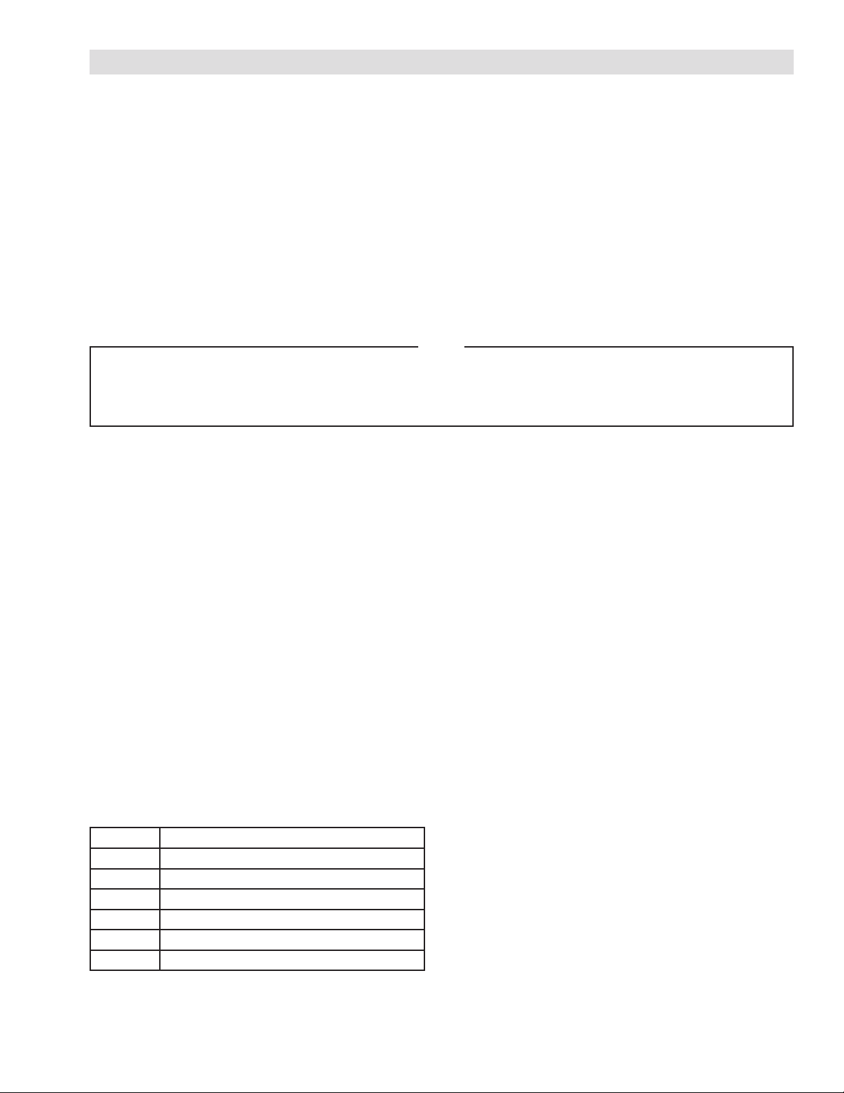
Full Scale
Parameter No. 0:
Set to the sensor type used per the table below.
SETTING SENSOR
0 TSA010K
1 TSA200, TSA1000
2 N/A
3 MB or SW Series
4, 5, 6 N/A
10-17 Reserved for Diagnostics. Refer to Section 6.
Parameter No. 1:
Set the placement of the decimal point in the
tension meter display, which will also limit the
maximum tension value that can be displayed.
0: 100 ~ 2000 Full Scale
0.0: 10.0 ~ 199.0 Full Scale
0.00: 1.00 ~ 19.90 Full Scale
Parameter No. 2:
Set the full scale tension. This will be the maximum
tension that the tension meter will be calibrated for
and is the full scale value used for setting output
levels and alarm triggers.
8
FORM NO. L21279-B-0513
Page 12
5. PARAMETER SETUP (continued...)
Tare Adjustment
1. Set the parameter to No. B.
2. With the sensing roller mounted on the sensor(s), ensure
that the web or any additional loading is not resting on
the roller or sensors.
3. Check and confirm that the display is not blinking. If
the display is blinking, the range of tare adjustment has
been exceeded, indicating either that the sensing roller
is not mounted correctly, or that the sensing roller is
too heavy. Verify the correct sensor type is selected
in Parameter No. 0 and verify sensor mounting.
4. Press the 8 button to begin the automatic tare
adjustment.
5. The tension display will fluctuate for several seconds
while the tare adjustment is performed, and when
complete, the indicated parameter code will change
to No C.
NOTE
If after exiting setup mode, the fifth digit begins
to blink the code digit “B”, the difference between
the left and right sensor voltages exceeds the
limit for the selected sensor type. It is advisable
to inspect the sensor mounting if this sensor
imbalance is unexpected. Refer to section 6.4
to disable the warning if desired.
1. Set the parameter to No. C.
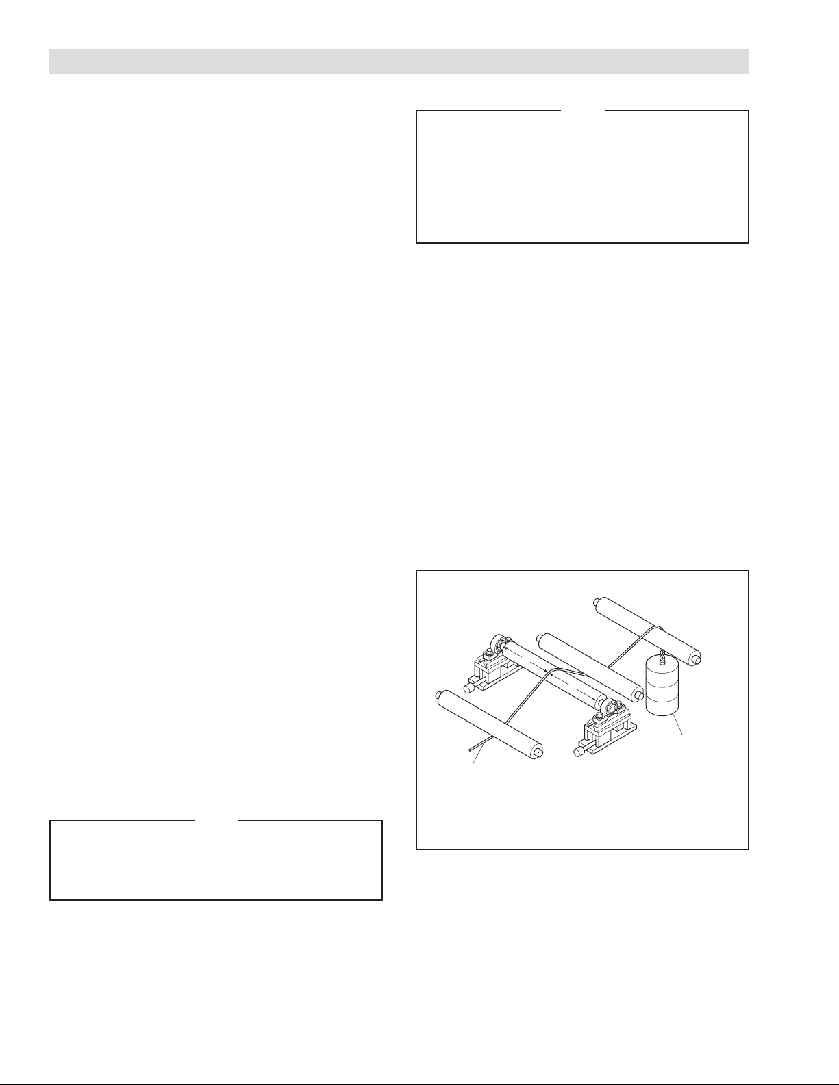
2. Thread a cord through the center of the sensing roller
using the same path as the web to be measured, and hang
a known weight as shown in Figure 5.1.
3. Enter the known weight with the use of the r/s buttons,
and then press 8 .
4. The tension indicator will fluctuate for several seconds
while the automatic span adjustment is made. The
indicated parameter code will change to No D. once
the adjustment is complete.
NOTE
If an error occurred during the span adjustment,
error code E1-X will be displayed. Refer to
Troubleshooting in Section 6 for steps to take
to correct the error.
A
A'
Thread a cord through
the center of the rolls
A = A'
FIGURE 5.1 Span Adjustment
Suspend a known
weight (W) from it
FORM NO. L21279-B-0513
9
Page 13
5. PARAMETER SETUP (continued...)
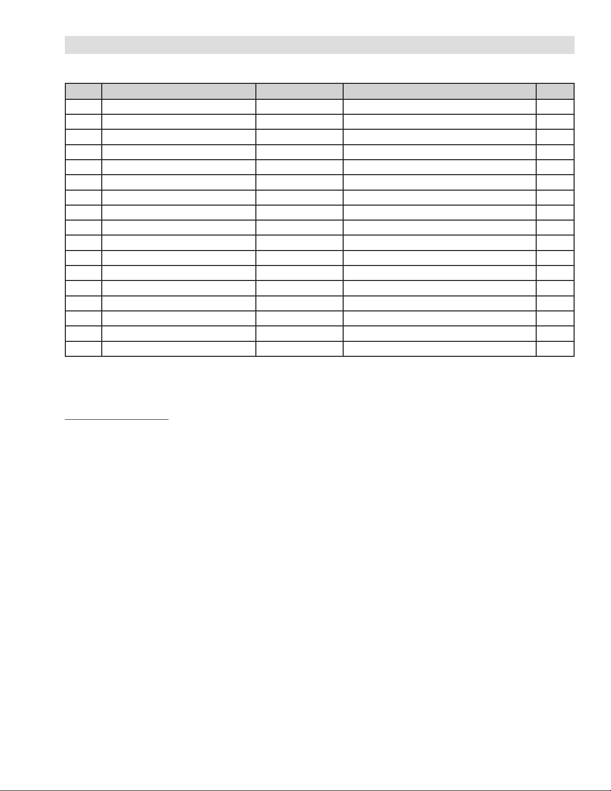
5.4 PARAMETER LIST
Code Function Description Default Value Set Range Unit
Tension sensor selection 0 0–6, 10–17* 0
0
Tension display decimal point selection 0 0, 0.0, 0.00 0
1
Tension full scale setting * 1.00g19.90, 10.0g199.0, 100g2000 x 10N
2
Display filter selection 1500 300, 600, 1000, 1500, 2000 msec
3
Control output filter selection 10 10, 20, 40, 60, 80, 100, 200, 500 msec
4
Control output type selection 0~10 0–5V, 0–10V, 4–20mA V or mA
5
Meter output filter selection 500 50, 100, 200, 500, 1000, 1500, 2000 msec
6
Indicator output filter selection 1000 800, 1000, 1500, 2000 msec
7
Minimum tension alarm setting 0 0 g Full Scale x 10N
8
Maximum/Unbalanced alarm selection 0 0, 1
9
Maximum tension alarm setting Full Scale 0 g Full Scale x 10N
A
Unbalanced alarm setting 10 0 g Full Scalle x10N
Automatic tare adjustment
B
Automatic span adjustment * 10% g Full Scale x 10N
C
Output Scaling 100 50 g150 %
D
Display/Hide alarm setting 0 0, 1
E
Equipment number 1 1 ~ 99
F
* Not all selections are valid for setup. See Section 5.3 for details.
5.5 PARAMETER DESCRIPTIONS
Calibration Parameters
The following parameters are used to adjust the tension display, full scale tension, and calibration of the unit. It is
recommended to refer to Section 5.3 for instructions on the calibration procedure.
0: Tension Sensor Selection
Sets the type of sensor used. See Section 5.3 for
details.
1: Decimal Placement
Set the location of decimal place. Select between 0,
0.0, 0.00. Must be set before calibration. Limits the full
scale range that can be set in Parameter 2. Changing
setting will require calibration to be performed.
2: Full Scale Tension
Sets the full scale value for tension. Can be set in the
range of 1 – 2,000. The range and number of digits is
limited by selection in Parameter 1.
5: Control Output Selection
Select the control output type.
Selectable values: 0—5V, 0—10V, 4—20mA.
NOTE: Only one output terminal, corresponding
to the selected output type should be wired to
equipment.
B: Tare Adjustment
Performs tare adjustment of load cell calibration. See
Section 5.3 for procedural details.
C: Span Adjustment
Performs span adjustment of load cell calibration. See
Section 5.3 for procedural details.
D: Output Scaling
Sets the scaling of the control output signal, normally
set to 100%. This setting will not affect the upper limit
(voltage or current) of the output.
Selectable range: 50–150%
10
FORM NO. L21279-B-0513
Page 14

5. PARAMETER SETUP (continued...)
Filtering Parameters
The following parameters are available to filter the display output, control outputs, and recording outputs.
3: Tension Display Filter
Sets the filter time for the display screen in
milliseconds.
Selectable values: 300, 600, 1000, 1500, 2000.
The larger the value, the more filtered the display
output will be. This does not affect meter or control
outputs.
4: Control Output Filter
Sets the filter time for the control output in
milliseconds.
Selectable values: 10, 20, 40, 60, 80, 100, 200,
500. The larger the value, the more filtered the
control output will be.
Alarm Parameters
Two alarm outputs are available, a Minimum Tension Alarm, and a selectable alarm for Maximum Tension or Unbalanced Load.
The alarms can also be set to display on the front panel. Refer to the following parameters for configuration of alarm outputs.
8: Minimum Tension Alarm Setting
Sets the minimum tension at which the output signal
of the Minimum Tension Alarm is turned on. Value is
set between 0 and Full Scale.
9: Maximum Tension / Unbalanced Alarm Selection
Selects between Maximum Tension Alarm or
Unbalanced Sensor Alarm.
Setting:
0 - Maximum Tension Alarm
1 - Unbalanced Sensor Alarm
6: Meter Output Filter
Sets the filter time for the meter output in
milliseconds.
Selectable values: 50, 100, 200, 500, 1000, 1500,
2000. The larger the value, the more filtered the
meter output will be.
7: Indicator Output Filter
Sets the filter time for the indicator output in
milliseconds.
Selectable values: 800, 1000, 1500, 2000. The
larger the value, the more filtered the indicator output
will be.
A: Maximum/Unbalanced Alarm Setting
Sets the condition of the alarm function set in
parameter 9.
Maximum Tension Alarm
Sets the maximum tension at which the output
signal of the alarm is turned on. Value is set
between 0 and Full Scale.
Unbalanced Sensor Alarm
Sets the maximum imbalance between the left &
right sensor input before the output signal of the
alarm is turned on. Value is set between 0 and
Full Scale.
E: Alarm Display
Sets whether to Display or Hide the maximum or
minimum tension alarms on the display.
When set to 0, the measured tension is always
displayed. When set to 1, HI or LO will display on
the screen during an alarm output.
Communication Parameters
The unit is equipped with a RS-485 communications system. The following Parameter is for configuring the RS-485
communications.
F: RS-485 Equipment Number
Sets the equipment number of the unit when using
RS-485 communications. Values between 1 and 99
may be set.
FORM NO. L21279-B-0513
11
Page 15
6. TROUBLESHOOTING
6.1 TENSION DISPLAY ERRORS
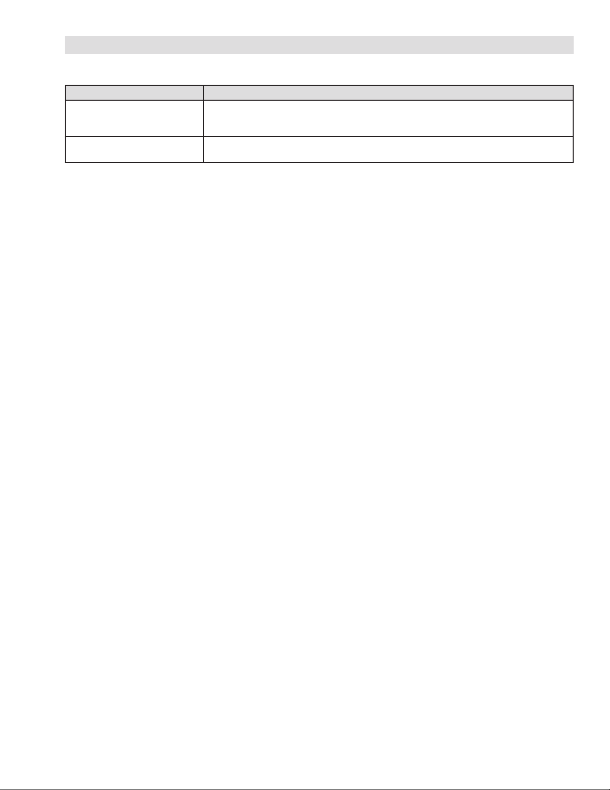
Display Error Explanation
The left-most digit blinks “B”:
The display stays at SEtUP and
does not change:
6.2 ZERO/SPAN ADJUSTMENT ERROR CODES
E0-0:
The tare adjustment load has been exceeded for a TSA200/1000 sensor. Verify the sensor roller loading and sensor
mounting. Press 8 to return to Parameter 0, and change sensor selection if not using a TSA200/1000 sensor.
E0-1:
The tare adjustment load has been exceeded for a TSA010K sensor. Verify the sensor roller loading and sensor
mounting. Press 8 to return to Parameter 0, and change sensor selection if not using a TSA010K sensor.
E0-2:
The tare adjustment load has been exceeded for a MB/SW sensor. Verify the sensor roller loading and sensor
mounting. Press 8 to return to Parameter 0, and change sensor selection if not using a MB/SW sensor.
The tare measurement between the sensors is imbalanced and is greater than the limit for the
selected sensor type. If this is not expected, verify the sensor mounting, otherwise refer to section
6.4 to disable the warning.
The unit has not yet been setup after initial power up. Refer to Section 5.2 - Initial Setup for
instructions.
E1-0:
The span load on the sensor is too small, and is below the span adjustment range of the amplifier. Repeat the span
adjustment with a heavier weight or lower the Full Scale Tension value and repeat the span adjustment with the
same weight. Press 8 to return to Parameter C to repeat the span adjustment.
E1-1:
The span adjustment range has been exceeded for a TSA sensor. Verify the sensor type selected in Parameter
No. 0, and if correct, repeat the adjustment procedure using a lighter load. Press 8 to return to Parameter C to
repeat the span adjustment.
E1-2:
The span adjustment range has been exceeded for an MB/SW sensor. Verify the sensor type selected in Parameter
No. 0, and if correct, repeat the adjustment procedure using a lighter load. Press 8 to return to Parameter C to
repeat the span adjustment.
6.3 OUTPUT TESTING FUNCTION
During testing, the Tension Meter can output a designated voltage and current from the control and meter output terminals.
The output signals will be at three levels (0%, 50%, and 100%) with respect to the full scale output of each output. Outputs
used for control are designated by Parameter 5 (control output type selection).
1. Press and hold the P button to enter the setup mode.
2. Select Parameter No. 5.
3. Press and hold the S + 8 button until the unit enters
output test and “5 OP” will be displayed. The output
will be at 0%.
4. Press the 8 button and the display will change to “5
50P”. The output will be at 50%.
5. Press the 8 button and the display will change to “5
100P”. The output will be at 100%.
6. Press the 8 button and the system returns to Parameter
5.
7. If the P button is pressed during step 3 to 5, the system
exits setup and returns to normal mode.
12
FORM NO. L21279-B-0513
Page 16
6. TROUBLESHOOTING (continued...)
6.4 SENSOR MEASUREMENT DIAGNOSTICS
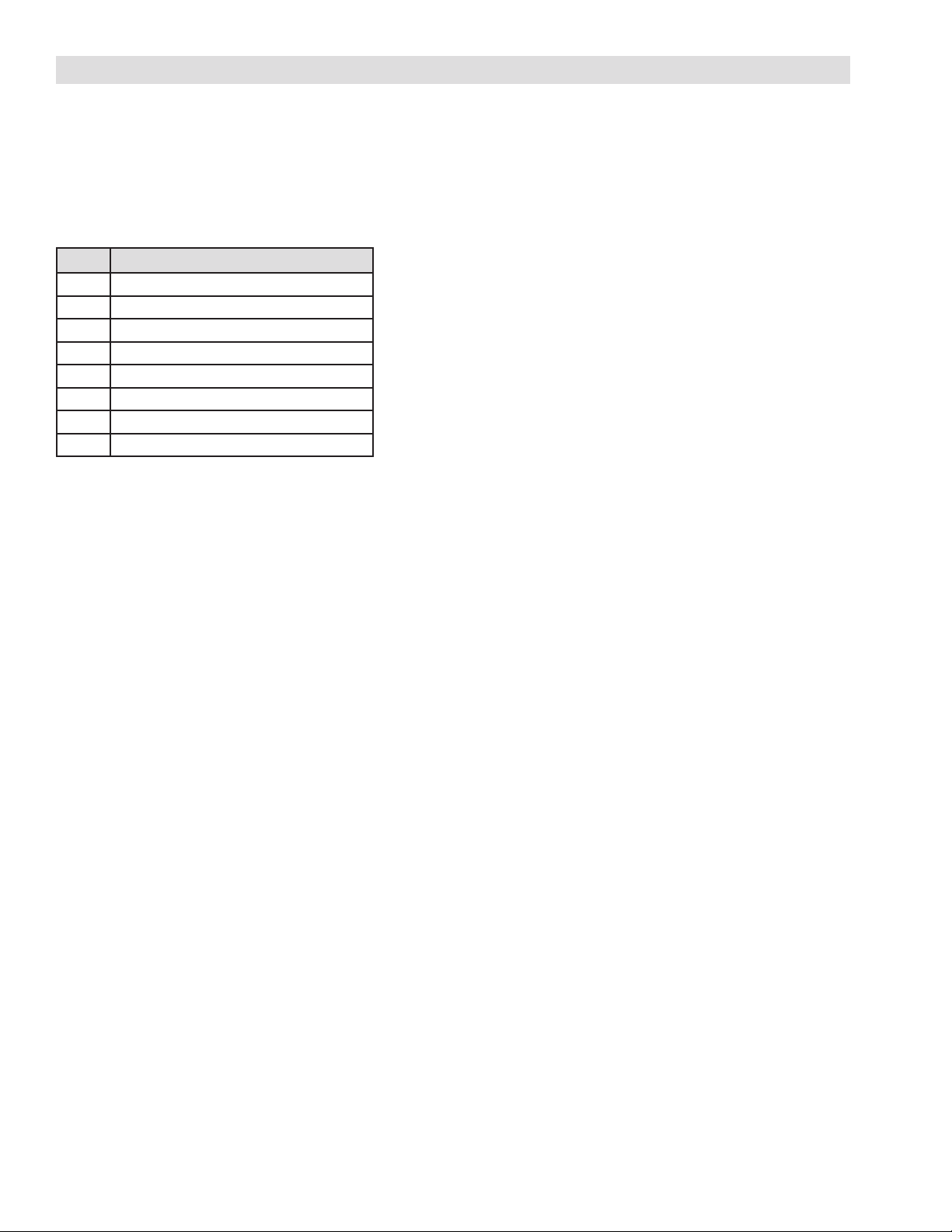
For use with troubleshooting, diagnostic parameters are available to measure sensor voltage and to review the results of the
automatic tare and span adjustments. The diagnostic parameters are a special function accessed via the Sensor Selection
(Parameter No. 0), and are read only and will not make settings changes. To operate the diagnostic options listed below,
hold P to enter setup mode, and enter the code value into parameter No. 0. The available diagnostics are listed in the table
below, followed by a detailed description of the operation of each available diagnostic.
Code Function
No. 1 Tare Voltage (mV)
10
11 No. 2 Tare Voltage (mV)
12 No. 1 Span Voltage (mV)
13 No. 2 Span Voltage (mV)
14* No. 1 Current Sensor Voltage (mV)
15* No. 2 Current Sensor Voltage (mV)
16 Reserved for Service Technician Use
17 Sensor Imbalance Warning Disable
*Do not operate selections 14 or 15 while measuring tension, as the control output will be incorrect.
Sensor Tare Calibration Voltage:
The following procedure is used for diagnostic purposes to display the calibrated tare voltage offset of a sensor. This
value cannot be set.
Select option 10 (No. 1 Sensor) or 11 (No. 2 Sensor) and press the 8 button to display value. The calibrated sensor
tare voltage offset will be displayed in millivolts.
Sensor Span Calibration Voltage:
The following procedure is used for diagnostic purposes to display the sensor’s measured voltage at full scale tension
based on the previous span adjustment calibration. This value cannot be set.
Select option 12 (No. 1 Sensor) or 13 (No. 2 Sensor) and press the 8 button to display value. The calibrated sensor
voltage corresponding to a full scale tension measurement will be displayed.
Measuring Sensor Input Voltage:
The following procedure is used for diagnostic purposes to display the currently measured sensor voltage. Do not use
this function during active tension measurement as the control output will be incorrect. Note that this is a coarse voltage
measurement for convenient diagnostic purposes, and will not replace a multimeter when accurate readings are required.
Select option 14 (No. 1 Sensor) or 15 (No. 2 Sensor) and press the 8 button to begin voltage measurement. The display
will show the measured voltage in millivolts. If the display blinks “-----", the sensor voltage exceeds the permissible range.
Disable Sensor Tare Imbalance Warning:
The sensor tare imbalance warning can be disabled by selecting option 17 of Parameter No. 0 and pressing the
8 button to display the current setting. Set the value to “1” and again press the 8 button to disable the warning
indicator. The warning is by default enabled with a setting of 0.
FORM NO. L21279-B-0513
13
Page 17
6. TROUBLESHOOTING (continued...)
Measuring Sensor Voltage with tare compensation during sensor operation:
The following procedure is used for diagnostic purposes to display the measured sensor voltage while the unit is
operating, and is not operated via setup mode. This voltage measurement is tare compensated, meaning OV will be
displayed when the tare weight is applied to the sensors. This function will only measure sensor voltage within the
calibrated measurement range. This voltage measurement function is for convenience, and is not suitable when an
accurate voltage measurement is required.
1. Press the S button to select the sensor to measure, indicated by the respective No. 1 or No. 2 indicator light.
2. Press the 8 button to display the sensor span voltage in millivolts. The selected sensor LED light will blink during
this time.
3. Press any key to return to tension measurement display.
7. MAINTENANCE
Regular scheduled maintenance is not required for either of the TM310T/TM340 Tension Meters. If precise accuracy is
required, periodic recalibration of the tare and span tension is recommended.
8. SPECIFICATIONS
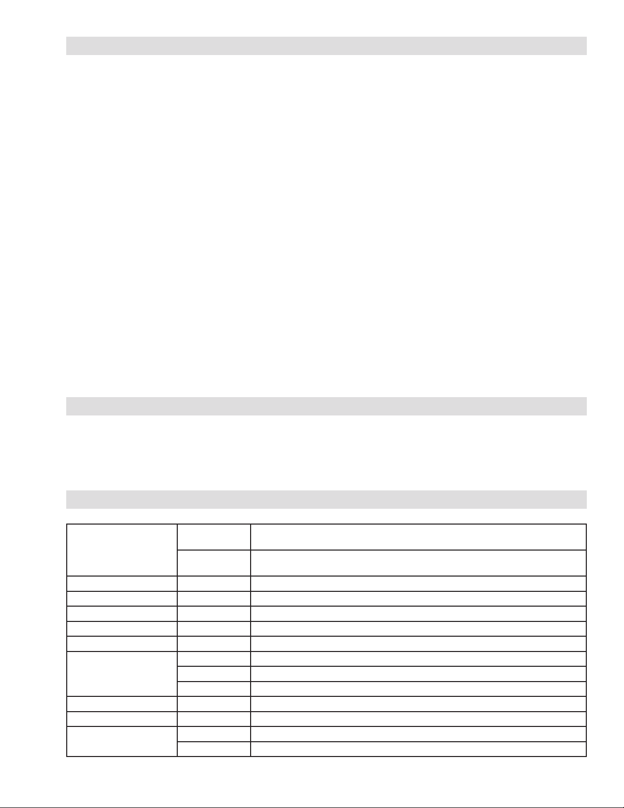
TM310T-AC
Power Voltage
Power Consumption 25 VA
Ambient Temperature 0°C to +50°C [32°F to 122°F]
Ambient Humidity 80% or less (no condensation)
Sensor Excitation Voltage +6V, ±15V
Sensor Inputs (2) Nexen MB, SW, and TSA Tension Sensors (Input range determined by sensor selection.)
Tension Outputs
Alarm Outputs 30V DC, 0.1A
Communication Function RS485 (Twin-wire half duplex system, 9600bps protocol)
Mounting Method
TM340-AC
TM310T-DC
TM340-DC
Control Output Selectable 0—5 V, 0—10 V, or 4—20 mA
Meter Output 0—1 mA
Monitor Output 0—5 V Individual Sensor Tension, 0—10 V Total Tension
TM310T DIN Rail Mount
TM340 Panel Mount
100V~240VAC 50/60Hz
24 VDC
14
FORM NO. L21279-B-0513
Page 18

Nexen Group, Inc.
560 Oak Grove Parkway
Vadnais Heights, MN 55127
800.843.7445
Fax: 651.286.1099
www.nexengroup.com
ISO 9001 Certified
9. WARRANTY
Warranties
Nexen warrants that the Products will (a) be free from any defects in material or workmanship for a period of 12 months
from the date of shipment, and (b) will meet and perform in accordance with the specifications in any engineering drawing
specifically for the Product that is in Nexen’s current product catalogue, or that is accessible at the Nexen website, or that is
attached to this Quotation and that specifically refers to this Quotation by its number, subject in all cases to any limitations
and exclusions set out in the drawing. NEXEN MAKES NO OTHER WARRANTY, EXPRESS OR IMPLIED, AND ALL
IMPLIED WARRANTIES, INCLUDING WITHOUT LIMITATION, IMPLIED WARRANTIES OF MERCHANTABILITY AND
FITNESS FOR A PARTICULAR PURPOSE ARE HEREBY DISCLAIMED. This warranty applies only if: (a) the Product has
been installed, used and maintained in accordance with any applicable Nexen installation or maintenance manual for the
Product; (b) the alleged defect is not attributable to normal wear and tear; (c) the Product has not been altered, misused or
used for purposes other than those for which it was intended; and (d) Buyer has given written notice of the alleged defect
to Nexen, and delivered the allegedly defective Product to Nexen, within one year of the date of shipment.
Exclusive Remedy
The exclusive remedy for the Buyer for any breach of any warranties provided in connection with this agreement will be,
at the election of Nexen: (a) repair or replacement with new, serviceably used, or reconditioned parts or products; or (b)
issuance of credit in the amount of the purchase price paid to Nexen by the Buyer for the Products.
Agent's Authority
Buyer agrees that no agent, employee or representative of Nexen has authority to bind Nexen to any affirmation, representation,
or warranty concerning the Products other than those warranties expressly set forth herein.
Limitation on Nexen’s Liability
TO THE EXTENT PERMITTED BY LAW NEXEN SHALL HAVE NO LIABILITY TO BUYER OR ANY OTHER PERSON
FOR INCIDENTAL DAMAGES, SPECIAL DAMAGES, CONSEQUENTIAL DAMAGES OR OTHER DAMAGES OF ANY
KIND OR NATURE WHATSOEVER, WHETHER ARISING OUT OF BREACH OF WARRANTY OR OTHER BREACH
OF CONTRACT, NEGLIGENCE OR OTHER TORT, OR OTHERWISE, EVEN IF NEXEN SHALL HAVE BEEN ADVISED
OF THE POSSIBILITY OR LIKELIHOOD OF SUCH POTENTIAL LOSS OR DAMAGE. For all of the purposes hereof, the
term "consequential damages" shall include lost profits, penalties, delay damages, liquidated damages or other damages
and liabilities which Buyer shall be obligated to pay or which Buyer may incur based upon, related to or arising out of its
contracts with its customers or other third parties. In no event shall Nexen be liable for any amount of damages in excess of
amounts paid by Buyer for Products or services as to which a breach of contract has been determined to exist. The parties
expressly agree that the price for the Products and the services was determined in consideration of the limitation on damages
set forth herein and such limitation has been specifically bargained for and constitutes an agreed allocation of risk which
shall survive the determination of any court of competent jurisdiction that any remedy herein fails of its essential purpose.
Inspection
Buyer shall inspect all shipments of Products upon arrival and shall notify Nexen in writing, of any shortages or other failures
to conform to these terms and conditions which are reasonably discoverable upon arrival without opening any carton or
box in which the Products are contained. Such notice shall be sent within 14 days following arrival. All notifications shall be
accompanied by packing slips, inspection reports and other documents necessary to support Buyer's claims. In addition
to the foregoing obligations, in the event that Buyer receives Products that Buyer did not order, Buyer shall return the
erroneously shipped Products to Nexen within thirty (30) days of the date of the invoice for such Products; Nexen will pay
reasonable freight charges for the timely return of the erroneously shipped Products, and issue a credit to Buyer for the
returned Products at the price Buyer paid for them, including any shipping expenses that Nexen charged Buyer. All shortages,
overages and nonconformities not reported to Nexen as required by this section will be deemed waived.
Limitation on Actions
No action, regardless of form, arising out of any transaction to which these terms and conditions are applicable may be
brought by the Buyer more than one year after the cause of action has accrued.
FORM NO. L21279-B-0513
15
 Loading...