

Page 1
AI R CHAM P PRODUCTS
User Manual
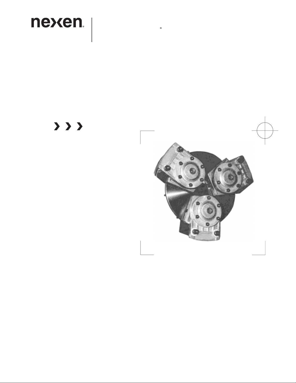
Tension Control Brake
Model TCB-7
(i)
FORM NO. L-20169-D-0501
Page 2
In accordance with Nexen’s established policy of constant product improvement, the specifications contained in this
manual are subject to change without notice. Technical data listed in this manual are based on the latest information
available at the time of printing and are also subject to change without notice.
Technical Support:
800-843-7445
(651) 484-5900
www.nexengroup.com
WARNING
Read this manual carefully before installation and operation.
Follow Nexen's instructions and integrate this unit into your system with care.
This unit should be installed, operated and maintained by qualified personnel ONLY.
Improper installation can damage your system or cause injury or death.
Comply with all applicable codes.
Copyright 2000 Nexen Group, Inc.
Nexen Group, Inc.
560 Oak Grove Parkway
Vadnais Heights, Minnesota 55127
ISO 9001 Certified
(ii)
Page 3

TABLE OF CONTENTS
Introduction----------------------------------------------------------------------------------------------------------------------------------------1
Installation ---------------------------------------------------------------------------------------------------------------------------------------- 2
Air Connections ---------------------------------------------------------------------------------------------------------------------------------3
Operation ------------------------------------------------------------------------------------------------------------------------------------------ 3
Maintenance -------------------------------------------------------------------------------------------------------------------------------------- 3
Troubleshooting----------------------------------------------------------------------------------------------------------------------------------4
Parts Replacement -----------------------------------------------------------------------------------------------------------------------------4
Replacement Parts -----------------------------------------------------------------------------------------------------------------------------6
Parts List ------------------------------------------------------------------------------------------------------------------------------------------- 7
Accessories --------------------------------------------------------------------------------------------------------------------------------------- 7
Warranties -----------------------------------------------------------------------------------------------------------------------------------------8
(iii)
Page 4
INTRODUCTION
Read this manual carefully, making full use of its explanations and instructions. The “Know How” of safe, continuous,
trouble-free operation depends on the degree of your understanding of the system and your willingness to keep all
components in proper operating condition. Pay particular attention to all NOTES, CAUTIONS, and WARNINGS to avoid
the risk of personal injury or property damage. It is important to understand that these NOTES, CAUTIONS, and
WARNINGS are not exhaustive. Nexen cannot possibly know or evaluate all conceivable methods in which service may
be performed, or the possible hazardous consequences of each method. Accordingly, anyone who uses a procedure
that is not recommended by Nexen must first satisfy themselves that neither their safety or the safety of the product will
be jeopardized by the service method selected.
Per OSHA regulations, Nexen recommends using a guard that will not restrict the flow of cooling
air around the unit if the unit has rotating parts. Contact your local Nexen Distributor for
information about guards designed for the Nexen TCB-7.
1
FORM NO. L-20169-D-0501
Page 5
INSTALLATION
Do not flange mount the TCB-7. Flange
mounting will result in damage to the TCB-7
Housing.
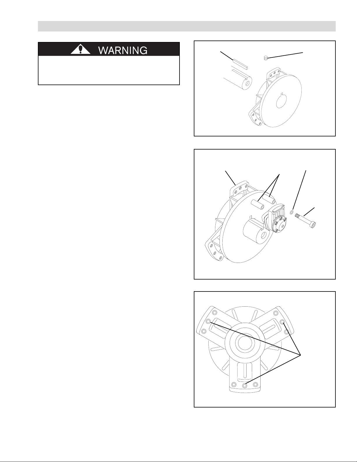
1. Insert the Nexen supplied Key (Item 6) into the
machine shaft (See Figure 1).
2. Slide the TCB-7 onto the machine shaft (See Figure 1).
Key
(Item 6)
Set Screw
(Item 3)
3. Tighten Set Screws (Item 3) to 7 Ft. Lbs. [9.5 N•m]
torque (See Figure 1).
NOTE: Runout of the Friction Disc Hub (Item 2)
must be less than 0.015'' [0.381 mm] TIR.
Runout is minimized if a dial indicator is used
as Set Screws (Item 3) are tightened. Place
contact tip of dial indicator on machined
surface of Friction Disc Hub to measure
runout.
4. Using the Flat Head Screw (Item 10) provided with
the Friction Facing (Item 9), secure a Friction Facing
to each Caliper Assembly.
5. Using the Spacers (Item 5), Lock Washers (Item 18),
and Socket Head Cap Screws (Item 19), secure
Caliper Assemblies to Housing (Item 1) (See Figure 2).
6. Tighten Socket Head Cap Screws (Item 19) to 27 Ft.
Lbs. [36.4 N•m] torque.
NOTE: The TCB-7 is designed to be held from
rotation by an arm or a linkage sufficient to
prevent rotation, but loose enough to avoid
thrust loads on the bearing or brake housing.
FIGURE 1
Housing
(Item 1)
FIGURE 2
Spacer
(Item 5)
Lock Washer
(Item 18)
Socket Head
Cap Screw
(Item 19)
7. Using a customer supplied 5/16 UNC Cap Screw,
secure a Torque Arm to the TCB-7 to prevent
rotation of the TCB-7 (See Figure 3).
Torque Arm
Anchoring
Points
FIGURE 3
2FORM NO. L-20169-D-0501
Page 6
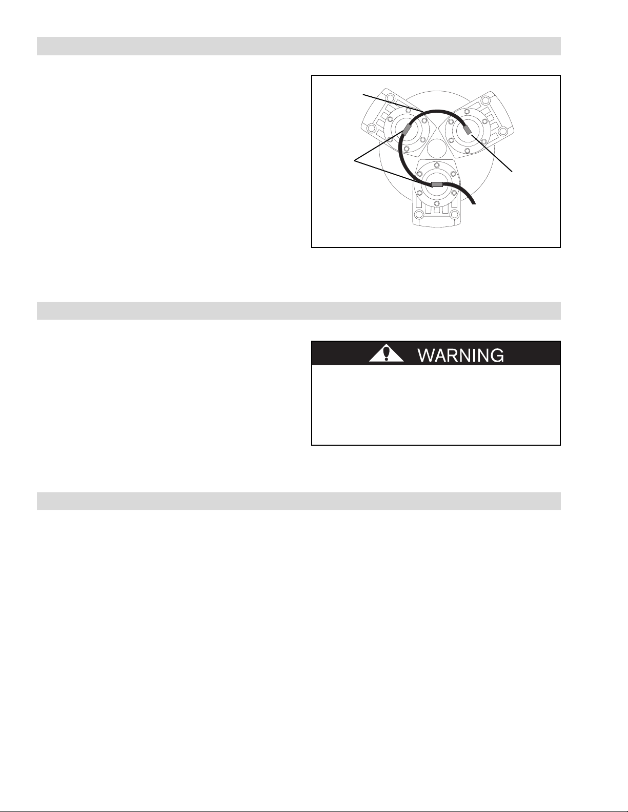
AIR CONNECTIONS
1. Install a Elbow Fitting (Item 15) into one Caliper
Assembly (See Figure 4).
2. Install the Tee Fittings (Item 16) into the remaining
Caliper Assemblies (See Figure 4).
3. Cut the Air Line (Item 17) to length and push it into
the Elbow and Tee Fittings (Items 15 and 16) (See
Figure 4).
4. Connect the remaining length of Air Line to the
control output port or connection (See Figure 4).
Air Line
(Item 17)
Tee
Fitting
(Item 16)
Elbow
Fitting
(Item 15)
To Control
5. Connect the air supply to the control input port or
connection (See Figure 4).
OPERATION
For optimum brake operation, connect the controls as
close to the TCB-7 as possible. Nexen Manufacturing
recommends the installation of a filter in the Air Line
ahead of the control.
For automatic tension control, use Nexen’s Electronic
Tension Control System. Contact your local Horton Web
Handling distributor or representative for information
concerning this product.
MAINTENANCE
Inspect all cap screws and set screws on a routine basis
to make sure they are tightened to the recommended
torque.
FIGURE 4
Never exceed the maximum operating speed
of 4000 RPM. Before placing TCB-7 into
service, check that the Socket Head Cap
Screws (Item 19) are tightened to 27 Ft. Lbs.
[36.4 N•m] torque (See Table 1).
Inspect Friction Facings and replace them when worn to
approximately 5/32" [4 mm] thick.
3
FORM NO. L-20169-D-0501
Page 7
TROUBLESHOOTING
MOTPMYS ESUACELBABORP NOITULOS
egagneoteruliaF.7-BCTehtotgnittegtonriA wolronoitcnuflamevlavlortnocrofkcehC
egagnesidoteruliaF.riadetsuahxenU .noitcnuflamevlavlortnocrofkcehC
rettahcrolaeuqsgnicaFnoitcirF.hgihooterusserpriA.erusserpriaecudeR
noitarbivroelbboW.gnitnuom7-BCTreporpmI fi7-BCTehtllatsnierdnagnitnuomkcehC
PARTS REPLACEMENT
.erusserpria
.noitacilppaehtrofgnicaFnoitcirFgnorW.gnicaFnoitcirFehtkcehC
.taergootsibuHcsiDnoitcirFehtfotuonuR ebtsumbuHcsiDnoitcirFehtfotuonuR
ehtfI.RIT]mm183.0[''510.0nahtssel
nahtretaergsituonurbuHcsiDnoitcirF
ebtsumcsideht]mm183.0[''510.0
.dellatsnier
.yrassecen
.tfahsytluaF fitiecalperdnatfahsehttcepsnI
.yrassecen
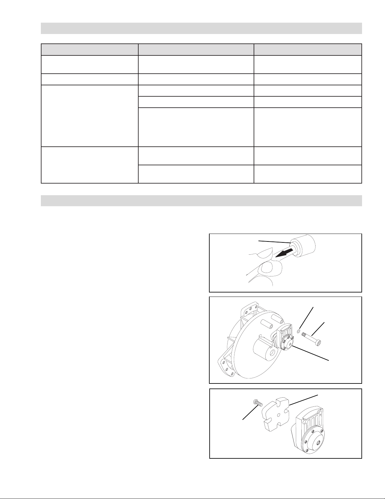
FRICTION FACINGS
1. Stop the machine and shut off the air supply to
the TCB-7.
2. Disconnect the Air Lines.
a. To disconnect the Air Line, push in on the
collar of the fitting and pull the Air Line out
(See Figure 5).
b. To reconnect the Air Line, push it into the
fitting until it stops.
3. Remove the Socket Head Cap Screws (Item 19) and
Lock Washers (Item 18) (See Figure 6).
4. Remove the Caliper Assembly from the Housing.
5. Remove the Flat Head Screw (Item 10) from the back
of the Caliper Assembly and remove the old Friction
Facing (Item 9) (See Figure 7).
6. Install a new Friction Facing (Item 9) and secure it to
the Caliper Assembly with a new Flat Head Screw
(Item 10). Tighten the Flat Head Screw to 18-19 In.
Lbs. [2.0-2.1 N•m].
Push collar in
to release.
FIGURE 5
Lock Washer
(Item 18)
Socket Head
Cap Screw
(Item 19)
Caliper
Assembly
FIGURE 6
Friction Facing
(Item 9)
7. Place the Caliper Assembly in position and secure it
to the Housing with the Socket Head Cap Screws
(Item 19) and Lock Washers (Item 18) (See Figure 6).
8. Tighten the Socket Head Cap Screws (Item 19) to
27 Ft. Lbs. [36.4 N•m] torque.
9. Reconnect the Air Lines.
Flat Head
Screw
(Item 10)
FIGURE 7
4FORM NO. L-20169-D-0501
Page 8
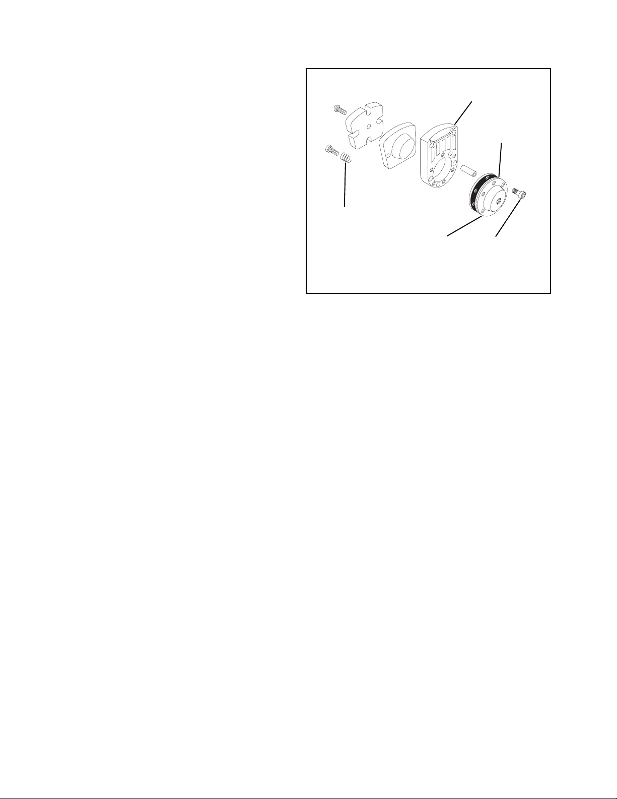
DIAPH RAG M
1. Proceed with Steps 1 - 4 of PARTS REPLACEMENT—FRICTION FACINGS.
2. Remove the six Socket Head Cap Screws (Item 20)
and Cover (Item 13) from the Cylinder (Item 11)
(See Figure 8).
3. Remove Diaphragm (Item 14) (See Figure 8).
NOTE: Internal Compression Springs (Item 41)
may also be removed at this time. These
springs are optional; the low air pressure
setting is more sensitive without the springs
(See Figure 8).
4. Install a new Diaphragm with the rubber (not fabric)
on the air side and reassemble the Caliper
Assembly.
5. Tighten the Socket Head Cap Screws (Item 20) to
5.5 Ft. Lbs. [7.45 N•m] torque (See Figure 8).
6. Proceed with Steps 7 - 9 of PARTS REPLACE-
MENT—FRICTION FACINGS.
Compression
Spring
(Item 41)
FIGURE 8
Cover
(Item 13)
Cylinder
(Item 11)
Diaphragm
(Item 14)
Socket Head
Cap Screws
(Item 20)
5
FORM NO. L-20169-D-0501
Page 9
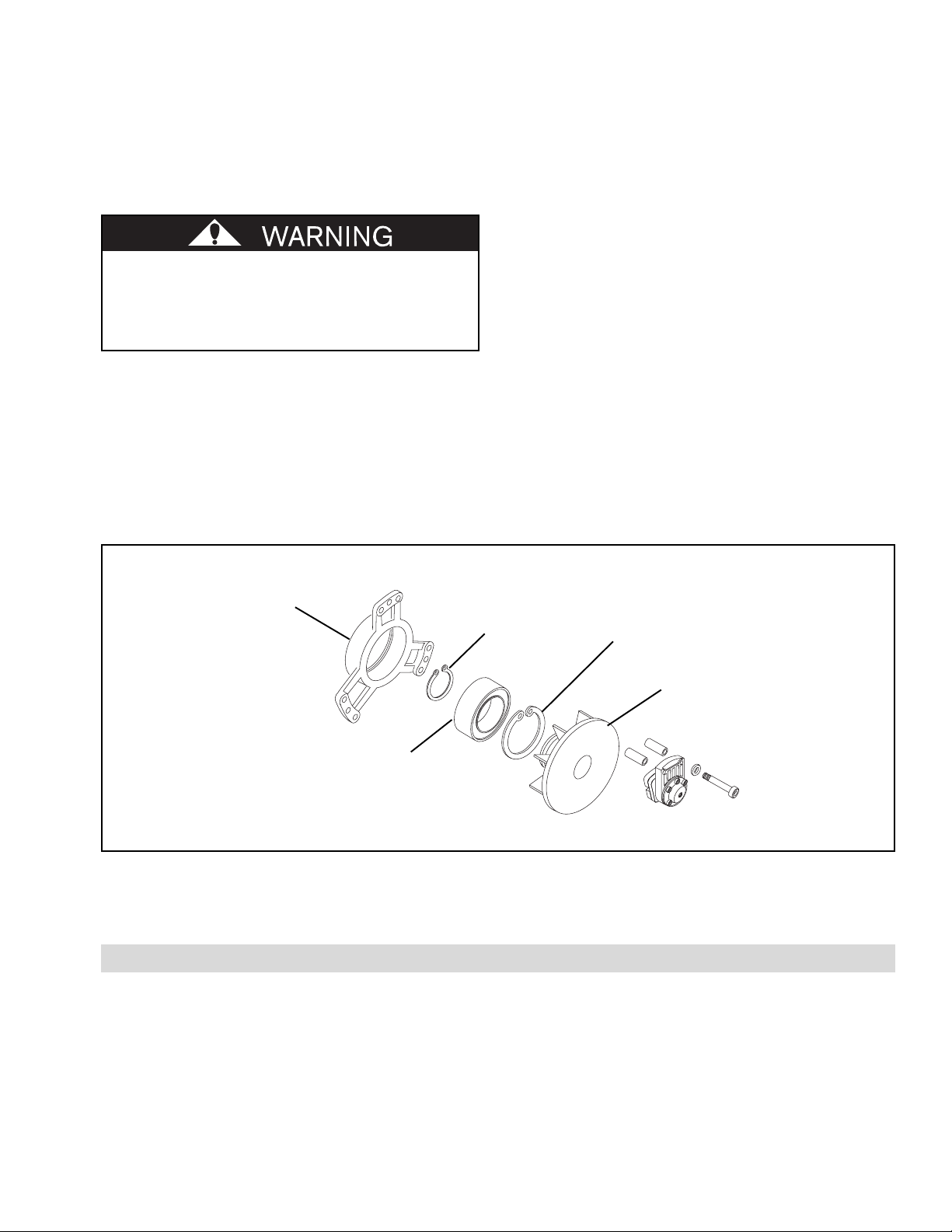
BEARING REPLACEMENT
1. Proceed with Steps 1 - 4 of PARTS REPLACEMENT—FRICTION FACINGS.
2. Loosen Set Screws (Item 3) and remove TCB-7
Housing and Rotor from machine shaft (See
INSTALLATION).
Special attention should be exercised when
working with retaining rings. Always wear
safety goggles when working with spring or
tension loaded fasteners or devices.
3. Remove Retaining Ring (Item 7) (See Figure 9).
4. Fully supporting Housing (Item 1), press the Friction
Disc Hub (Item 2) out of the Bearing (Item 4) and
Housing (Item 1) (See Figure 9).
5. Remove the Retaining Ring (Item 8) (See Figure 9).
6. Fully supporting Housing (Item 1), press the old
Bearing (Item 4) out of the Housing (Item 1) (See
Figure 9).
7. Clean the bearing bore of the Housing with safety
solvent making sure all Loctite® residue is removed.
8. Apply an adequate amount of Loctite® 680 to evenly
coat the outer race of the new Bearing (Item 4); then,
align the new Bearing with the bore of Housing and
press the new Bearing into place.
9. Install Retaining Ring (Item 8) (See Figure 9).
10. Slide Friction Disc Hub (Item 2) into Bearing (Item 4)
and Housing (Item 1) (See Figure 9).
11. Install Retaining Ring (Item 7) (See Figure 9).
12. Proceed with Steps 7 - 9 of PARTS REPLACE-
MENT—FRICTION FACINGS.
13. Install TCB-7 (See INSTALLATION).
Housing
(Item 1)
Bearing
(Item 4)
Retaining Ring
FIGURE 9
REPLACEMENT PARTS
The item or balloon number for all Nexen products is used
for part identification on all product parts lists, product
price lists, unit assembly drawings, bills of materials, and
instruction manuals.
(Item 7)
Retaining Ring
(Item 8)
Friction
Disc Hub
(Item 2)
When ordering replacement parts, specify model
designation, item number, part description, and quantity.
Purchase replacement parts through your local Nexen
Distributor.
6FORM NO. L-20169-D-0501
Page 10
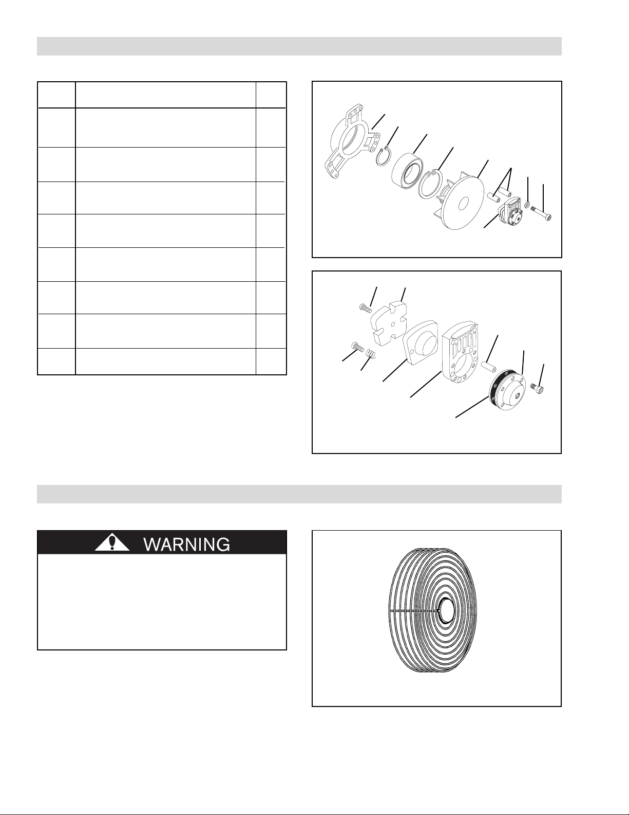
PARTS LIST
ITEM DESCRIPTION QTY
1 Housing 1
2 Friction Disc Hub 1
3 Set Screw (Not Shown) 3
4 Bearing 1
5 Spacer 2
6 Key (Not Shown) 1
7 Retaining Ring (Ext.) 1
8 Retaining Ring (Int.) 1
9 Friction Facing 3
10 Flat Head Screw 3
11 Cylinder 1
12 Piston 1
13 Cover 1
14 Diaphragm 1
15 Elbow Fitting (Not Shown) 1
16 Tee Fitting (Not Shown) 1
17 Air Line (Not Shown) -18 Lock Washer (Ext. Tooth) 6
19 Socket Head Cap Screw 6
20 Socket Head Cap Screw 6
21 Spring Pin 2
40 Socket Head Cap Screw 2
41 Compression Spring 2
1
Quantity shown is for one (1) Caliper Assembly only.
1
7
4
8
2
5
18
19
1
1
1
1
FIGURE 10
10
9
See
Figure 11
21
1
1
1
40
13
20
41
12
11
ACCESSORIES
Per OSHA regulations, Nexen recommends
using a guard that will not restrict the flow of
cooling air around the unit if the unit has
rotating parts. Contact your local Nexen
Distributor for information about guards
designed for the Nexen TCB-7.
FIGURE 11
14
CALIPER ASSEMBLY
FIGURE 12
TCB-7 HOUSING GUARD P/N 835186
7
FORM NO. L-20169-D-0501
Page 11

WARRANTIES
Warranties
Nexen warrants that the Products will be free from any defects in material or workmanship for a period of 12 months
from the date of shipment. NEXEN MAKES NO OTHER WARRANTY, EXPRESS OR IMPLIED, AND ALL IMPLIED
WARRANTIES, INCLUDING WITHOUT LIMITATION, IMPLIED WARRANTIES OF MERCHANTABILITY AND
FITNESS FOR A P ARTICULAR PURPOSE ARE HEREBY DISCLAIMED. This warranty applies only if (a) the Product
has been installed, used and maintained in accordance with any applicable Nexen installation or maintenance manual
for the Product; (b) the alleged defect is not attributable to normal wear and tear; (c) the Product has not been altered,
misused or used for purposes other than those for which it was intended; and (d) Buyer has given written notice of the
alleged defect to Nexen, and delivered the allegedly defective Product to Nexen, within one year of the date of
shipment.
Exclusive Remedy
The exclusive remedy of the Buyer for any breach of the warranties set out above will be, at the sole discretion of Nexen,
a repair or replacement with new, serviceably used or reconditioned Product, or issuance of credit in the amount of the
purchase price paid to Nexen by the Buyer for the Products.
Limitation of Nexen’s Liability
T O THE EXTENT PERMITTED BY LAW NEXEN SHALL HAVE NO LIABILITY T O BUYER OR ANY OTHER PERSON
FOR INCIDENTAL DAMAGES, SPECIAL DAMAGES, CONSEQUENTIAL DAMAGES OR OTHER DAMAGES OF
ANY KIND OR NATURE WHA T SOEVER, WHETHER ARISING OUT OF BREACH OF WARRANTY OR OTHER
BREACH OF CONTRACT, NEGLIGENCE OR OTHER TORT, OR OTHERWISE, EVEN IF NEXEN SHALL HAVE
BEEN ADVISED OF THE P O S S IBILITY OR LIKELIHOOD OF SUCH POTENTIAL LOSS OR DAMAGE. For all of
the purposes hereof, the term “consequential damages” shall include lost profits, penalties, delay images, liquidated
damages or other damages and liabilities which Buyer shall be obligated to pay or which Buyer may incur based upon,
related to or arising out of its contracts with its customers or other third parties. In no event shall Nexen be liable for
any amount of damages in excess of amounts paid by Buyer for Products or services as to which a breach of contract
has been determined to exist. The parties expressly agree that the price for the Products and the services was
determined in consideration of the limitation on damages set forth herein and such limitation has been specifically
bargained for and constitutes an agreed allocation of risk which shall survive the determination of any court of
competent jurisdiction that any remedy herein fails of its essential purpose.
Limitation of Damages
In no event shall Nexen be liable for any consequential, indirect, incidental, or special damages of any nature whatsoever, including without limitation, lost profits arising from the sale or use of the Products.
Warranty Claim Procedures
To make a claim under this warranty, the claimant must give written notice of the alleged defect to whom the Product
was purchased from and deliver the Product to same within one year of the date on which the alleged defect first
became apparent.
Nexen Group, Inc.
560 Oak Grove Parkway
Vadnais Heights, MN 55127
800.843.7445
Fax: 651.286.1099
www.nexengroup.com
ISO 9001 Certified
8FORM NO. L-20169-D-0501
 Loading...