

Page 1
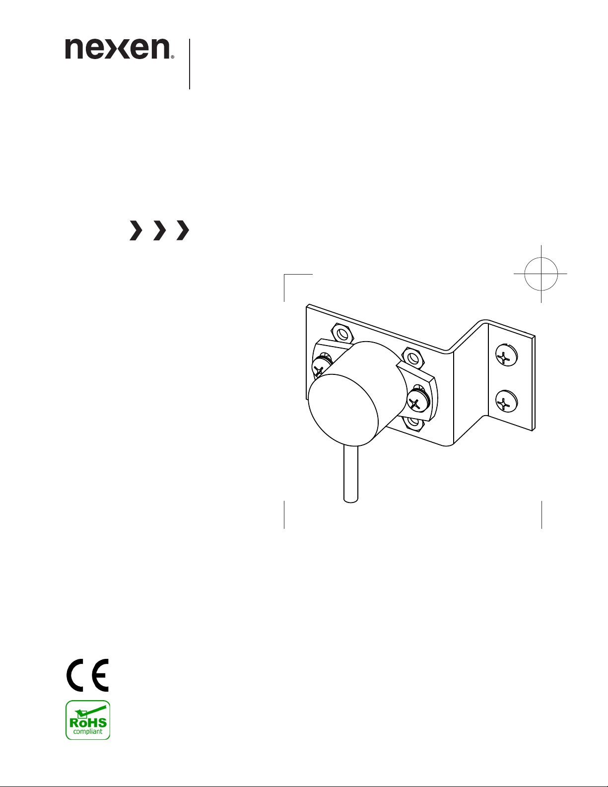
Dancer Position Sensor
WEB CONTROL PRODUCTS
User Manual
DPS60A Dual
1
FORM NO. L-21261-B-0214
Page 2
In accordance with Nexen’s established policy of constant product improvement, the specifications contained in this
manual are subject to change without notice. Technical data listed in this manual are based on the latest information
available at the time of printing and are also subject to change without notice.
Technical Support: 800-843-7445
(651) 484-5900
www.nexengroup.com
DANGER
Read this manual carefully before installation and operation.
Follow Nexen’s instructions and integrate this unit into your
system with care. This unit should be installed, operated and
maintained by qualified personnel ONLY. Improper installation
can damage your system, cause injury or death. Comply with
all applicable codes.
This document is the original, non-translated, version.
Conformity Declaration: In accordance with Appendix II B of CE Machinery Directive (2006/42/EC):
A Declaration of Incorporation of Partly Completed Machinery evaluation for the applicable EU directives
was carried out for this product in accordance with the Machinery Directive. The declaration of incorporation
is set out in writing in a separate document and can be requested if required.
This machinery is incomplete and must not be put into service until the machinery into which it is to be
incorporated has been declared in conformity with the applicable provisions of the Directive.
Copyright 2014 Nexen Group, Inc.
FORM NO. L-21261-B-0214
Nexen Group, Inc.
560 Oak Grove Parkway
Vadnais Heights, Minnesota 55127
ISO 9001 Certified
2
Page 3

TABLE OF CONTENTS
Introduction ---------------------------------------------------------------------------------------------------------------------------4
Installation -----------------------------------------------------------------------------------------------------------------------------4
Direct Connection ------------------------------------------------------------------------------------------------------------------ 4
Coupling Connection -------------------------------------------------------------------------------------------------------------5
Electrical Connections ------------------------------------------------------------------------------------------------------------ 6
Adjustment ----------------------------------------------------------------------------------------------------------------------------6
Troubleshooting ---------------------------------------------------------------------------------------------------------------------7
Mounting Dimensions -------------------------------------------------------------------------------------------------------------8
Parts List ------------------------------------------------------------------------------------------------------------------------------- 9
Replacement Parts ----------------------------------------------------------------------------------------------------------------- 9
Specifications ------------------------------------------------------------------------------------------------------------------------ 9
Warranty -----------------------------------------------------------------------------------------------------------------------------10
3
FORM NO. L-21261-B-0214
Page 4
INTRODUCTION
+.10
-.00
6.00
+.004
-.000
.236
min.
Nexen Dancer Position Sensors have been designed to accurately measure the rotational movement of a dancer arm.
This family of sensors use Hall Effect technology which provide for benefits such as infinite resolution, low drag, and
no mechanical wear. They are ideally suited to work with Nexen’s Dancer Position Controllers.
INSTALLATION
NOTE: Mounting of the Dancer Position Sensor can
be accomplished two ways. The first is the Direct
Connection method and the second is the Coupling
Connection method. Review the instructions for both
methods and select the method best suited for your
application.
NOTE: For serial number prior to 2269020, refer to
Literature 21260.
DIRECT CONNECTION
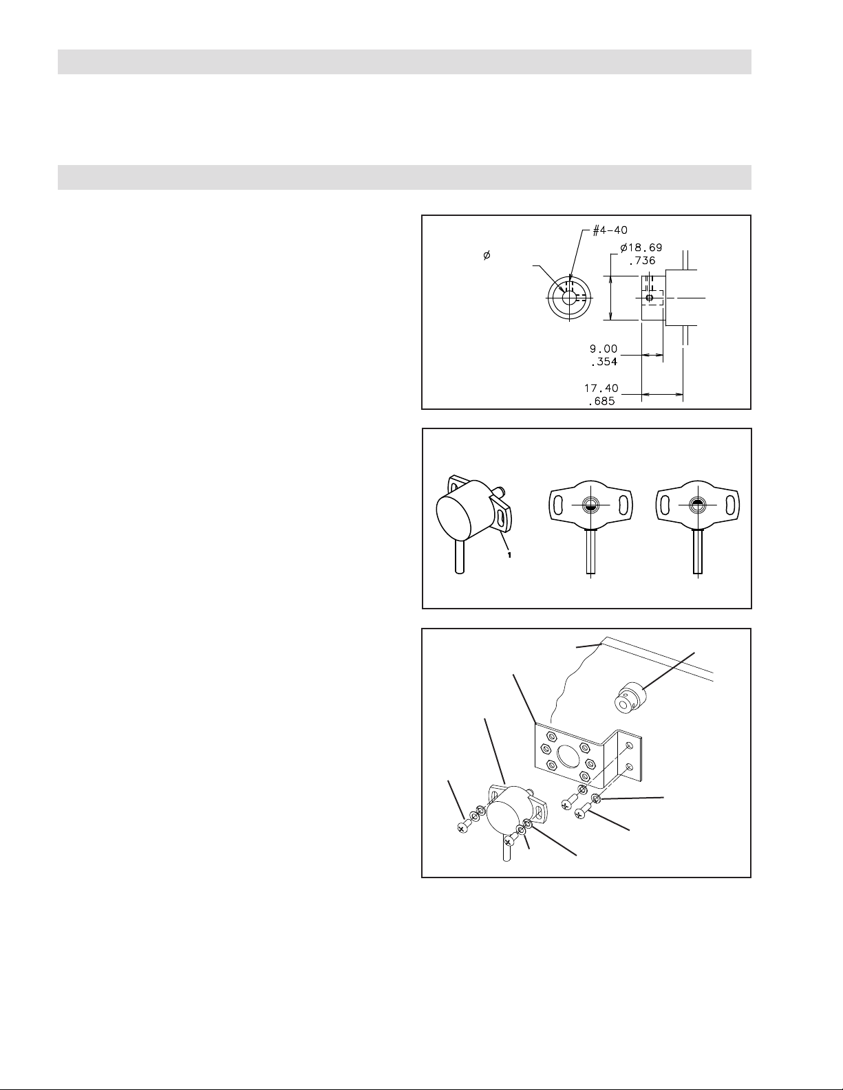
1. Verify that the dancer arm pivot shaft’s end complies
with the dimensions given (See Figure 1).
2. Drill and tap two 4-40 threaded holes 90° apart for
two, .25” set screws.
3. The orientation of the Dancer Position Sensor (Item1)
must be as shown in order to match the mid output of
the Dancer Position Sensor to the mid travel position
of the dancer arm (See Figure 2). The DPS60A Dual
sensor has two measurement ranges allowing for
flexibility in the mounting position (See Figure 7).
4. Attach Dancer Position Sensor (Item 1) to one of the
three hole configurations on the Bracket (Item 3) with
two shorter Pan Head Screws (Item 4), Flat Washers
(Item 6), and Lock Washers (Item 5). (See Figure 3).
5. Hand tighten the screws just enough to prevent it from
moving during installation (See Figure 3).
6. Slide the Dancer Position Sensor (Item 1) into the shaft
until the Bracket (Item 3) contacts the machine’s side
frame (See Figure 3).
Figure 1
Back
Figure 2
4
Front
1
3
Midpoint of
output when
viewed from front.
Machine
Frame
Alternative
midpoint of
output.
Dancer
Arm
Pivot
Shaft
5
7. Mark the location of the Bracket’s two mounting
holes.
8. Remove the Dancer Position Sensor (Item 1) and
Bracket (Item 3); then, drill and tap two 8-32 threaded
holes centered within the marks drawn in Step 7.
9. With the dancer arm held firmly in its mid travel
position, slide the Dancer Position Sensor (Item 1) into
the shaft while making sure the sensor shaft marking
is pointing toward the cable (See Figure 3).
FORM NO. L-21261-B-0214
7
Figure 3
6
5
10. Using the two set screws, secure the dancer pivot
shaft to the sensor shaft by tightening the screws
evenly.
11. Using the two longer Pan Head Screws (Item 7) and
Lock Washers (Item 5), secure the Bracket (Item 3)
to the machine’s side frame (See Figure 3).
4
Page 5
COUPLING CONNECTION
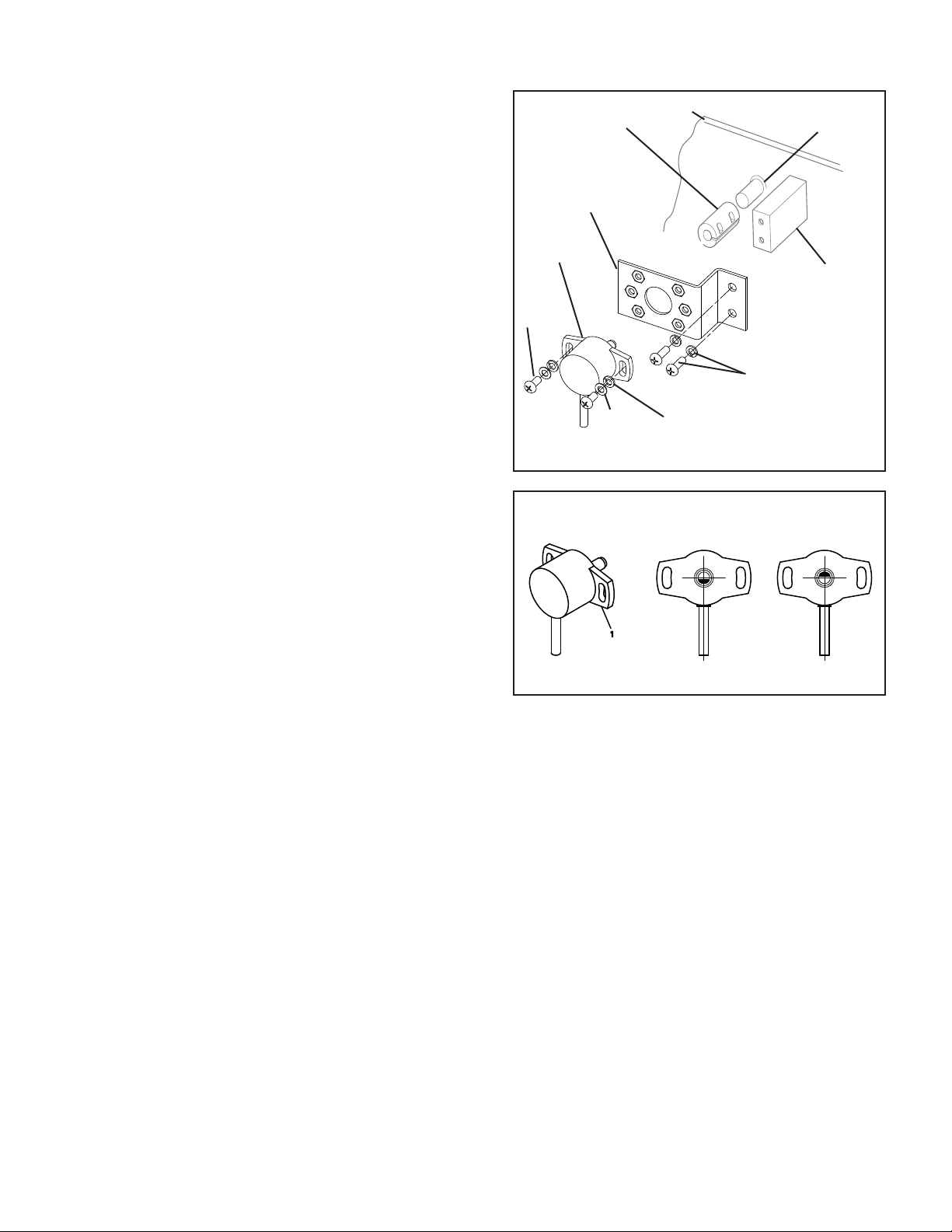
1. Purchase a zero backlash flexible shaft coupler that
accommodates the diameter of the sensor shaft (Item
1) on one end and the dancer arm pivot shaft on the
other end (See Figures 4 and 7).
2. Slide the shaft coupler onto the dancer arm pivot shaft,
inserting the shaft no further than half the thickness
of the coupler clamp; then, tighten the clamp around
the shaft (See Figure 4).
3. The orientation of the Dancer Position Sensor (Item1)
must be as shown in order to match the mid output of
the Dancer Position Sensor to the mid travel position
of the dancer arm (See Figure 5). The DPS60A Dual
sensor has two measurement ranges allowing for
flexibility the in mounting position (See Figure 7).
4. Attach Dancer Position Sensor (Item 1) to one of
the three hole configurations on the Bracket (Item 3)
with the two shorter Pan Head Screws (Item 4), Flat
Washers (Item 6), and Lock Washers (Item 5) (See
Figure 4).
5. Hand tighten the screws just enough to prevent sensor
from moving during installation (See Figure 4).
Coupling
1
4
Figure 4
Front
Machine
Frame
3
Customer supplied
6
viewed from front.
5
Midpoint of
output when
Lock Washers.
Dancer
Arm
Pivot
Shaft
Spacer
Block
Screws and
Alternative
midpoint of
output.
6. Slide the Dancer Position Sensor (Item 1) into the
coupling (See figure 4).
7. Measure the distance from the bottom of the Bracket
(Item 3) to the machine’s side frame. Fabricate a
spacer block to make up the distance between the
Bracket and the machine’s side frame (See Figure
4).
8. Slide the Dancer Position Sensor (Item 1) into the
coupling again with the spacer block in place on the
machine’s side frame and mark the location for the
bracket’s two mounting holes.
9. Remove the Dancer Position Sensor (Item 1) and
Bracket (Item 3); then, drill and tap two 8-32 threaded
holes centered within the marks drawn in Step 8.
10. With the dancer arm held firmly in its mid travel
position, slide the Dancer Position Sensor (Item 1)
into the coupling again making sure the sensor shaft
marking is pointing toward the cable.
Insert the shaft no further than half the thickness of
the coupling clamp.
Back
Figure 5
11. Tighten the clamp around the sensor shaft (See Figure
4).
12. Using customer supplied 8-32 screws and lock
washers, secure the Bracket (Item 3) to the customer
supplied spacer block and the machine’s side frame
(See Figure 4).
5
FORM NO. L-21261-B-0214
Page 6
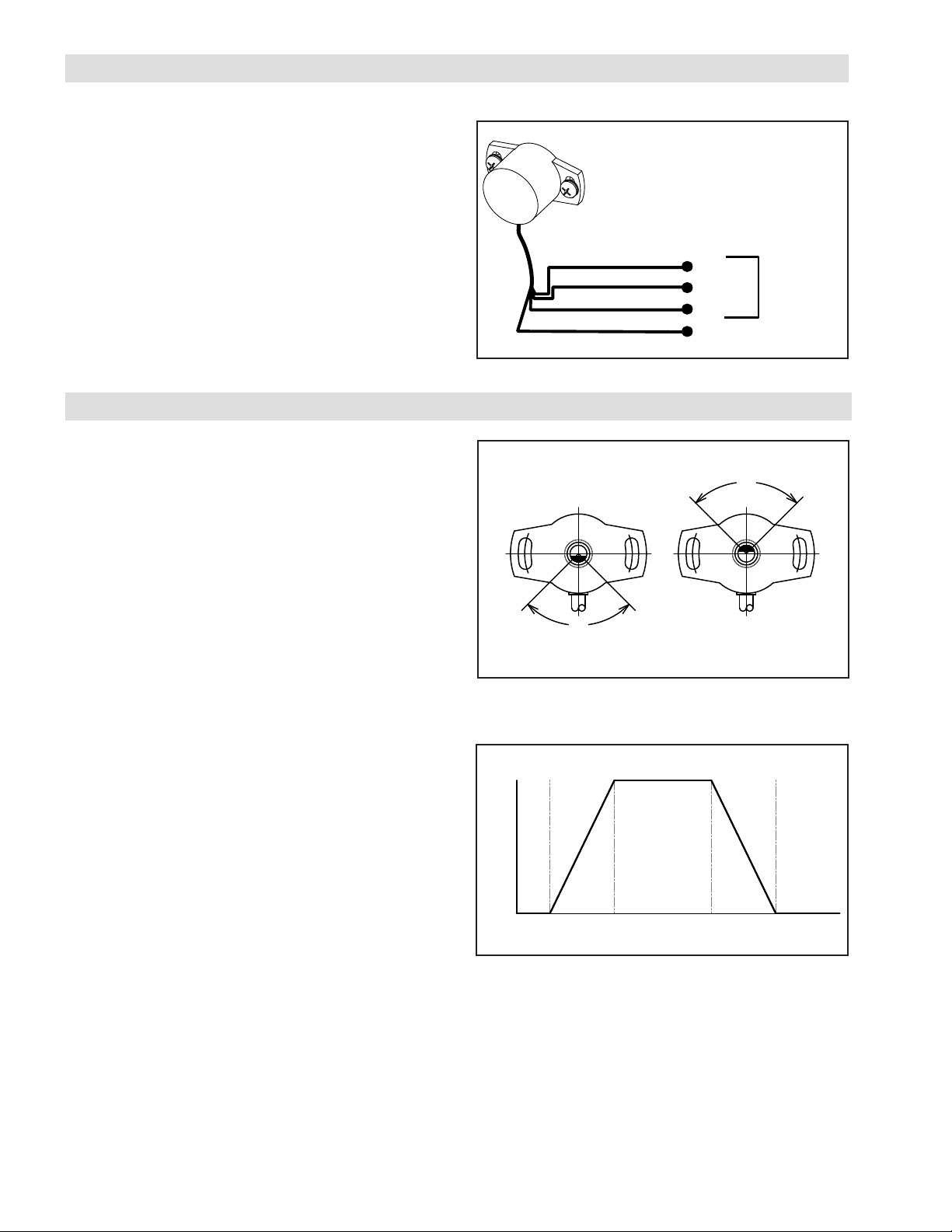
+24 VDC
SHIELD WIRE
BROWN
WHITE
GREEN
SIGNAL
DANCER
POSITION
CONTROLLER
COM
EARTH GROUND
ELECTRICAL CONNECTIONS
1. Route the Dancer Position Sensor signal cable through
the machine.
2. Connect the signal cable to a controller (See Figure
6).
NOTE: The shield wire from the signal cable should
be earth grounded at the controller.
If noise is still present on the position signal, ensure
the sensor shaft has a low impedance connection to
earth ground through the machine frame.
ADJUSTMENT
1. Apply power to the Dancer Position Sensor.
2. Refer to Installation for the proper alignment of the
sensor.
Figure 6
150°
10V
180°
60°
210°
0V
3. Using a voltmeter, measure the voltage across the
green (+) and brown (-) wires (See figure 6). The
voltage reading must match the supply voltage for
proper operation (See Specifications).
4. Measure the sensor output voltage across the white
(+) and brown (-) wires. With the dancer arm held in
its mid travel position, the sensor output should be
approximately +5 VDC. If it is not, then slightly loosen
the sensor’s fasteners and rotate the sensor until the
voltage reading is +5 VDC. Refer to Figure 7 and 8
for mid travel position and sensor voltage output.
5. Tighten the fasteners securely to prevent the sensor
from moving.
6. Move the dancer arm through its full range of motion
and check that the voltage changes between 0 and
10 VDC. If the output voltage stops changing as the
dancer arm is moving, slightly loosen the sensor’s
fasteners and rotate the sensor. If this persists,
the angular movement of the dancer arm might
exceed the measurement range for the sensor (See
Specifications).
10V
30°
60°
0°
0V
330°
Note: Sensor viewed from front.
Figure 7 Dual Output Range
10V
5V
0V
330° 0° 30° 150° 180° 210° 330°
Figure 8 Sensor Output
7. Trim back any unused wires to prevent electrical
shorting problems.
8. At this time the installation and adjustment of the
dancer position sensor is complete. Refer to the
controller manual for any further setup and calibration
procedures.
FORM NO. L-21261-B-0214
6
Page 7

TROUBLESHOOTING
SYMPTOM PROBABLE CAUSE SOLUTION
No voltage from Dancer Position Sensor.
Dancer Position Sensor output does not
change.
Position Sensor Signal is erratic with no
dancer arm movement.
Dancer Position Sensor output voltage is
not changing through the full 30 degree
or 60 degree range.
No power to the Dancer Position sensor Turn on the power to the Dancer Position
Controller. Connect the Dancer Position
Sensor according to Figure 6.
Input power polarity is backwards Check polarity of the power supply. Con-
nect the Dancer Position Sensor according to Figure 6.
No power to the Dancer Position Sensor Turn on the power to the Dancer Position
Controller. Connect the Dancer Position
Sensor according to Figure 6.
Dancer Position Sensor misaligned Align the Dancer Position Sensor accord-
ing to Figure 2 for Mid Point of Output
and according to the instructions in the
INSTALLATION and ADJUSTMENT sections.
Dancer arm exceeds the capacity of the
sensor.
Electrical noise interfering with sensor. Connect the shield directly to earth
Dancer Position Sensor misaligned Refer to Figure 2 for proper alignment
Switch to a DPS60A or restrict the swing
for the Dancer arm. Refer to SPECIFICATIONS
ground. If noise persists, ensure the
sensor shaft has a low impedance path to
earth ground. See WIRING INSTALLATION GUIDE
of the sensor. The shaft marking should
point toward the cable for mid-travel position of the dancer arm.
7
FORM NO. L-21261-B-0214
Page 8
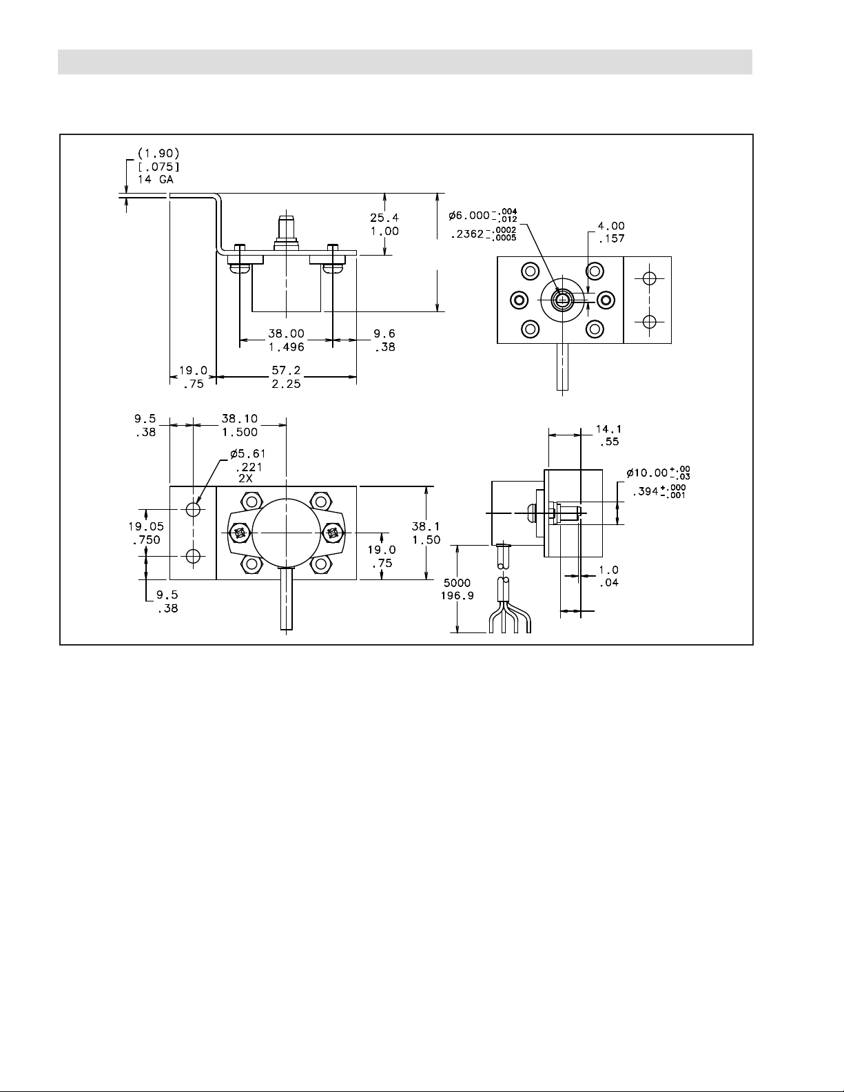
MOUNTING DIMENSIONS
9.9
.390
48.6
1.91
DANCER POSITION SENSOR
Figure 9
FORM NO. L-21261-B-0214
8
Page 9
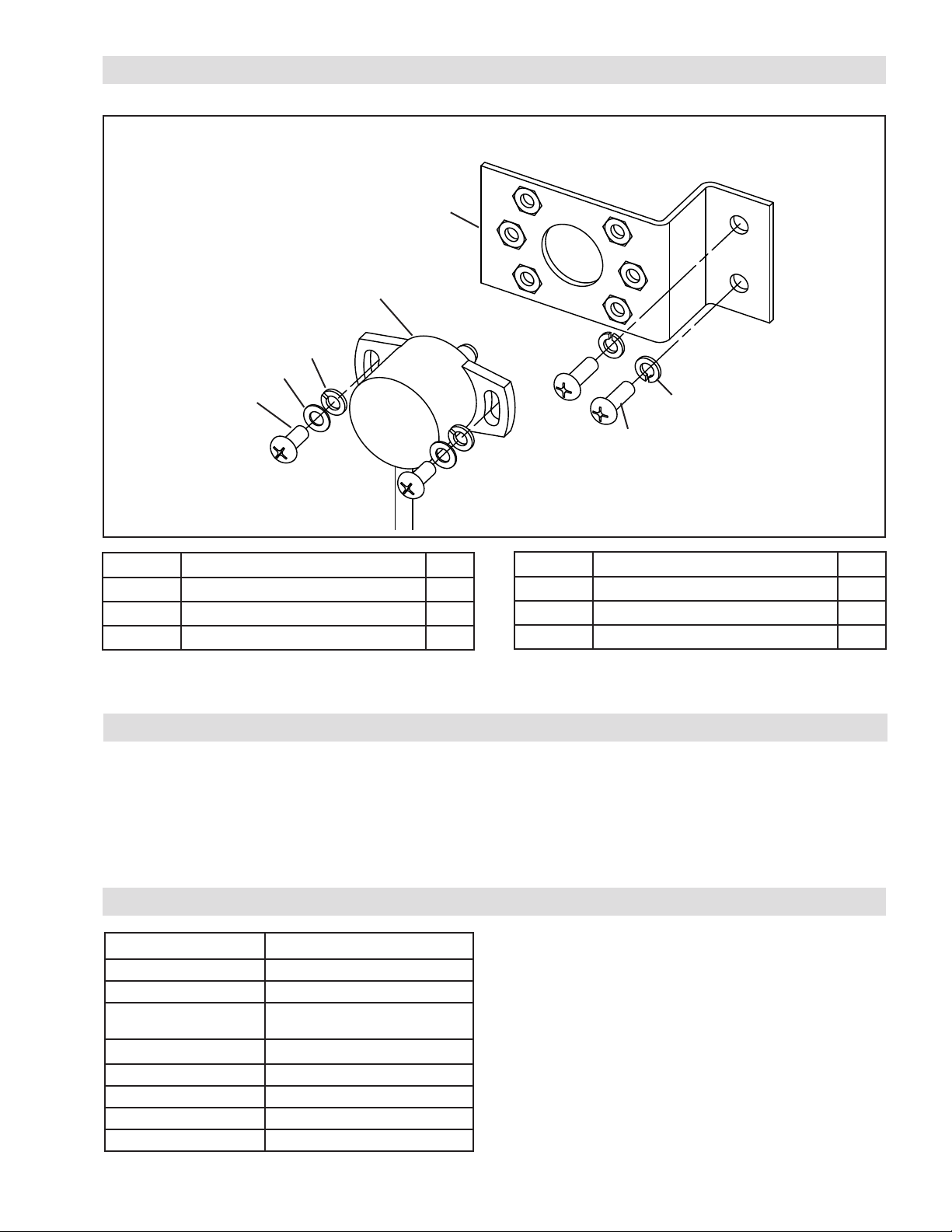
PARTS LIST
3
1
5
6
4
7
5
Figure 10
ITEM DESCRIPTION QTY
1
3
4
Dancer Position Sensor
Bracket
Pan Head Phillips Screw
1
1
2
REPLACEMENT PARTS
The item or balloon number for all Nexen products is used
for part identification on all product parts lists, product
price lists, unit assembly drawings, bills of materials, and
instruction manuals.
SPECIFICATIONS
DPS60A DUAL
Product Number 964518
Supply Voltage 24 ± 6 VDC
Output Voltage 0~10VDC
Reverse Polarity Protection -30VDC maximum
Temperature -40oF [-40oC] to 185oF [85oC]
Enclosure IP65
Accuracy ± 1º
Angular Rotation ± 30o maximum
@ max. angular rotation
ITEM DESCRIPTION QTY
5
6
7
Lock Washer
Flat Washer
Pan Head Phillips Screw
4
2
2
When ordering replacement parts, specify model
designation, item number, part description, and quantity.
Purchase replacement parts through your local Nexen
Distributor.
Note: DPS60A sensors prior to S/N 2269020 have only
one measurement range. Refer to Literature 21260 for
instructions and specifications.
9
FORM NO. L-21261-B-0214
Page 10

WARRANTY
Nexen Group, Inc.
560 Oak Grove Parkway
Vadnais Heights, MN 55127
800.843.7445
Fax: 651.286.1099
www.nexengroup.com
ISO 9001 Certified
Warranties
Nexen warrants that the Products will be free from any defects in material or workmanship for a period of 12 months
from the date of shipment. NEXEN MAKES NO OTHER WARRANTY, EXPRESS OR IMPLIED, AND ALL IMPLIED
WARRANTIES, INCLUDING WITHOUT LIMITATION, IMPLIED WARRANTIES OF MERCHANTABILITY AND FITNESS
FOR A PARTICULAR PURPOSE ARE HEREBY DISCLAIMED. This warranty applies only if (a) the
Product has been installed, used and maintained in accordance with any applicable Nexen installation or maintenance
manual for the Product; (b) the alleged defect is not attributable to normal wear and tear; (c) the Product has not been
altered, misused or used for purposes other than those for which it was intended; and (d) Buyer has given written notice
of the alleged defect to Nexen, and delivered the allegedly defective Product to Nexen, within one year of the date of
shipment.
Exclusive Remedy
The exclusive remedy of the Buyer for any breach of the warranties set out above will be, at the sole discretion of Nexen,
a repair or replacement with new, serviceably used or reconditioned Product, or issuance of credit in the amount of the
purchase price paid to Nexen by the Buyer for the Products.
Limitation of Nexen’s Liability
TO THE EXTENT PERMITTED BY LAW NEXEN SHALL HAVE NO LIABILITY TO BUYER OR ANY OTHER PERSON
FOR INCIDENTAL DAMAGES, SPECIAL DAMAGES, CONSEQUENTIAL DAMAGES OR OTHER DAMAGES OF
ANY KIND OR NATURE WHATSOEVER, WHETHER ARISING OUT OF BREACH OF WARRANTY OR OTHER
BREACH OF CONTRACT, NEGLIGENCE OR OTHER TORT, OR OTHERWISE, EVEN IF NEXEN SHALL HAVE
BEEN ADVISED OF THE POSSIBILITY OR LIKELIHOOD OF SUCH POTENTIAL LOSS OR DAMAGE. For all of
the purposes hereof, the term “consequential damages” shall include lost profits, penalties, delay images, liquidated
damages or other damages and liabilities which Buyer shall be obligated to pay or which Buyer may incur based upon,
related to or arising out of its contracts with its customers or other third parties. In no event shall Nexen be liable for any
amount of damages in excess of amounts paid by Buyer for Products or services as to which a breach of contract has
been determined to exist. The parties expressly agree that the price for the Products and the services was determined
in consideration of the limitation on damages set forth herein and such limitation has been specifically bargained for and
constitutes an agreed allocation of risk which shall survive the determination of any court of competent jurisdiction that
any remedy herein fails of its essential purpose.
Limitation of Damages
In no event shall Nexen be liable for any consequential, indirect, incidental, or special damages of any nature whatsoever,
including without limitation, lost profits arising from the sale or use of the Products.
Warranty Claim Procedures
To make a claim under this warranty, the claimant must give written notice of the alleged defect to whom the Product was
purchased from and deliver the Product to same within one year of the date on which the alleged defect first became
apparent.
FORM NO. L-21261-B-0214
10
 Loading...