

Page 1
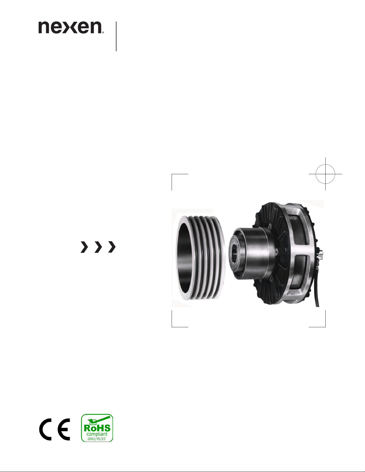
AIR CHAMP® PRODUCTS
User Manual
Models DPC-9T and DPC-11T
FORM NO. L-20070-F-1209
i
FORM NO. L-20070-F-1209
Page 2

In accordance with Nexen’s established policy of constant product improvement, the specifications contained in this manual
are subject to change without notice. Technical data listed in this manual are based on the latest information available at
the time of printing and are also subject to change without notice.
Technical Support: 800-843-7445
(651) 484-5900
www.nexengroup.com
DANGER
Read this manual carefully before installation and operation.
Follow Nexen’s instructions and integrate this unit into your
system with care. This unit should be installed, operated and
maintained by qualified personnel ONLY. Improper installation
can damage your system, cause injury or death. Comply with
all applicable codes.
This document is the original, non-translated, version.
Conformity Declaration: In accordance with Appendix II B of CE Machinery Directive (2006/42/EC):
A Declaration of Incorporation of Partly Completed Machinery evaluation for the applicable EU directives was
carried out for this product in accordance with the Machinery Directive. The declaration of incorporation is set
out in writing in a separate document and can be requested if required.
This machinery is incomplete and must not be put into service until the machinery into which it is to be incorporated
has been declared in conformity with the applicable provisions of the Directive.
Copyright 2009 Nexen Group, Inc.
FORM NO. L-20070-F-1209
Nexen Group, Inc.
560 Oak Grove Parkway
Vadnais Heights, Minnesota 55127
ISO 9001 Certified
ii
Page 3

TABLE OF CONTENTS
Table of Contents
General Specifications ----------------------------------------------------------------------------------------------------------------------- 1
General Safety Precautions -----------------------------------------------------------------------------------------------------------------1
Introduction ---------------------------------------------------------------------------------------------------------------------------------------2
Installation -----------------------------------------------------------------------------------------------------------------------------------------2
Support Bushing -------------------------------------------------------------------------------------------------------------------------2
Pilot Mount Clutch -----------------------------------------------------------------------------------------------------------------------3
Sheave Mount -----------------------------------------------------------------------------------------------------------------------------4
Lubrication -----------------------------------------------------------------------------------------------------------------------------------------4
Air Connections ---------------------------------------------------------------------------------------------------------------------------------5
Shaft End Mounting ---------------------------------------------------------------------------------------------------------------------5
Through Shaft Mounting ---------------------------------------------------------------------------------------------------------------6
Operation ------------------------------------------------------------------------------------------------------------------------------------------7
Parts Replacement ----------------------------------------------------------------------------------------------------------------------------8
Friction Facing -----------------------------------------------------------------------------------------------------------------------------8
O-rings ---------------------------------------------------------------------------------------------------------------------------------------9
Bearings -------------------------------------------------------------------------------------------------------------------------------------9
Replacement Parts ---------------------------------------------------------------------------------------------------------------------------11
Warranty -----------------------------------------------------------------------------------------------------------------------------------------12
iii
FORM NO. L-20070-F-1209
Page 4
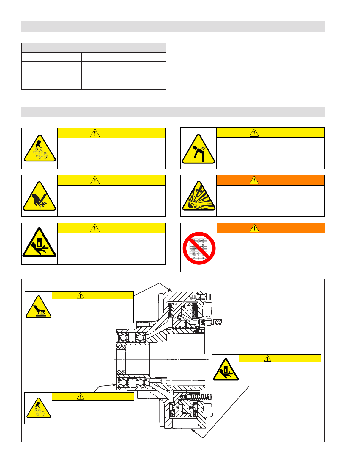
GENERAL SPECIFICATIONS
Specifications
Torque Up to 1243 Nm (11000 in-lbs)
Actuation Pressure 1 - 5.5 bar (14.5 - 80 psi)
Service Temperature 4.5º - 104º C (40º - 220º F)
Approximate Weight Up to 45.5 kg (100 lbs)
GENERAL SAFETY PRECAUTIONS
CAUTION
Use appropriate guarding for moving
components. Failure to guard could
result in serious bodily injury.
CAUTION
Watch for sharp features when
interacting with this product. The parts
have complex shapes and machined
edges.
CAUTION
This product has possible pinch points.
Care should be taken when interacting
with this product.
CAUTION
Surface temperature may exceed safe
handling limits during operation. Do not
touch.
CAUTION
Use lifting aids and proper lifting
techniques when installing, removing or
placing this product in service.
WARNING
This product is capable of emitting a
spark if misused, therefore is not
recommended for use in any explosive
environment.
WARNING
Ensure proper guarding of the product is
used. Nexen recommends the machine
builder design guarding in compliance
with OSHA 29 CFR 1910 “Occupational Safety and Health Hazards.”
Use appropriate guarding for moving
components. Failure to guard could
result in serious bodily injury.
FORM NO. L-20070-F-1209
CAUTION
This product has possible pinch points.
Care should be taken when interacting
with this product.
CAUTION
1
Page 5
INTRODUCTION
Nexen’s DPC (Dual Friction Plate) Clutches are designed
to mount on shaft ends, or through shafts using a customer
supplied Q.D. (Quick Detachable) Bushing. The dual
friction plate design eliminates thrust loading of bearings
when the DPC Clutch is connected to a bearing supported
Flywheel, Sprocket, or Sheave.
Five components are combined to install Nexen’s DPC
Clutch, and a Pilot Mount Clutch, or as a Sheave Clutch.
The five basic components (each sold separately) are:
Pilot Clutch Assembly, Sheave, Rotary Air Union Cap, Q.
D. Bushing, and Rotary Air Union.
The inner and outer assembles of the DPC Clutch rotate
independently.
INSTALLATION
NOTE
All DPC Clutch installations require a Q.D. (Quick
Detachable) Bushing. Refer to Table 1 for Q. D.
Bushing Specifications.
When mounted on a through shaft, the outer clutch assembly rotates, and upon engagement, the inner clutch
assembly becomes the driven unit.
When mounted on a continually running shaft, the inner
clutch assembly rotates, and upon engagement, the outer
clutch assembly becomes the driven member.
Nexen recommends mounting the DPC Clutch with the
outer clutch assembly rotating continuously; taking advantage of the cooling effect of the fins to dissipate heat
generated when the clutch is engaged.
TABLE 1 Q.D. Bushing Specifications
Model
Bushing
Type
Bore
Pull-up Bolt
Tightening Torque
DPC-9T SK 2.375 15 ft-lbs [20 Nm]
DPT-11T SF 2.875 10 ft-lbs [41 Nm]
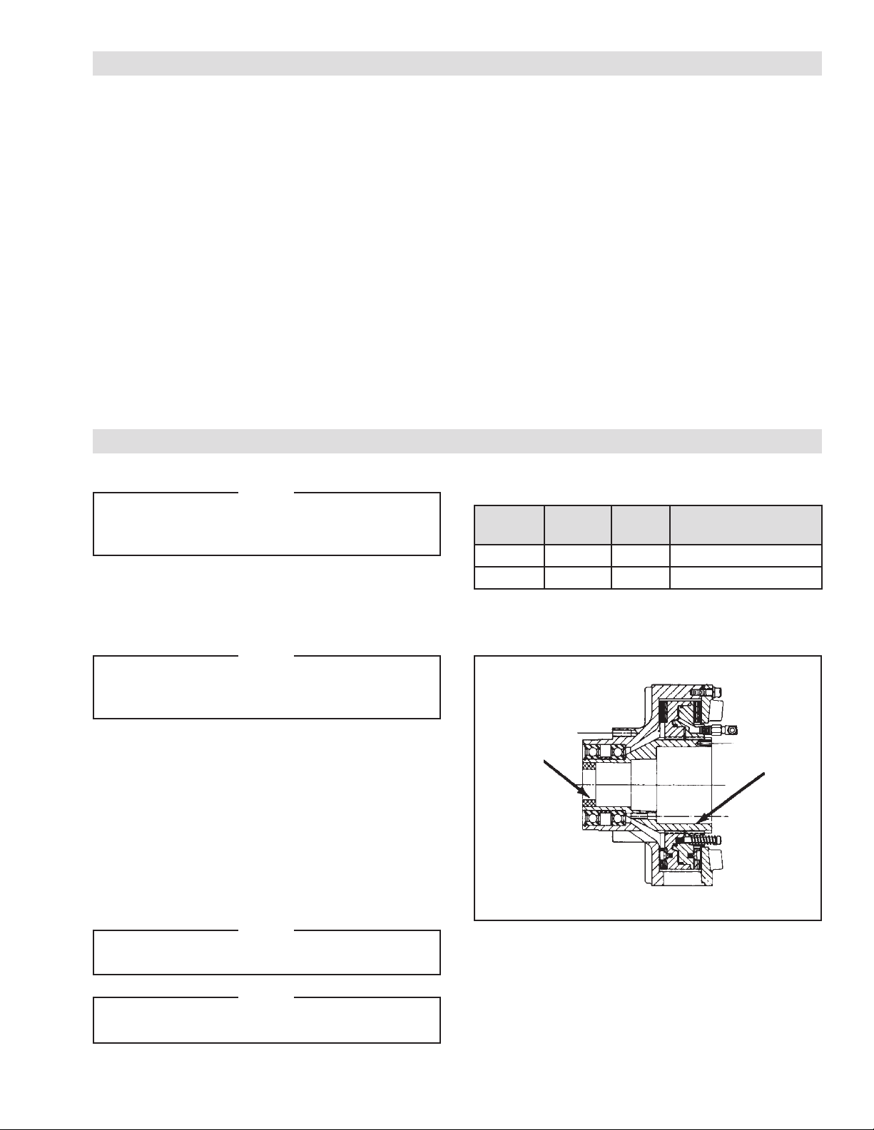
SUPPORT BUSHING
NOTE
The Support Bushing provides radial load
support at the shaft, and is used when bore
sizes smaller than standard are required.
REFER TO FIGURE 1.
1. Place “DPC” Clutch, Friction Disc side down, and
support large end of Splined Hub (Item 1).
2. Insert Support Bushing into bore of Splined Hub
(Item 1).
3. Apply even pressure around the entire diameter
of the Support Bushing, and press the Support
Bushing into the Splined Hub (Item 1).
NOTE
Do not use a hammer to install Support Bushing.
Nexen recommends a small arbor press.
NOTE
On “DPC-9T” the Support Bushing fits flush
with the end of the Splined Hub.
Support
Bushing
1
FIGURE 1
2
FORM NO. L-20070-F-1209
Page 6
INSTALLATION (continued)
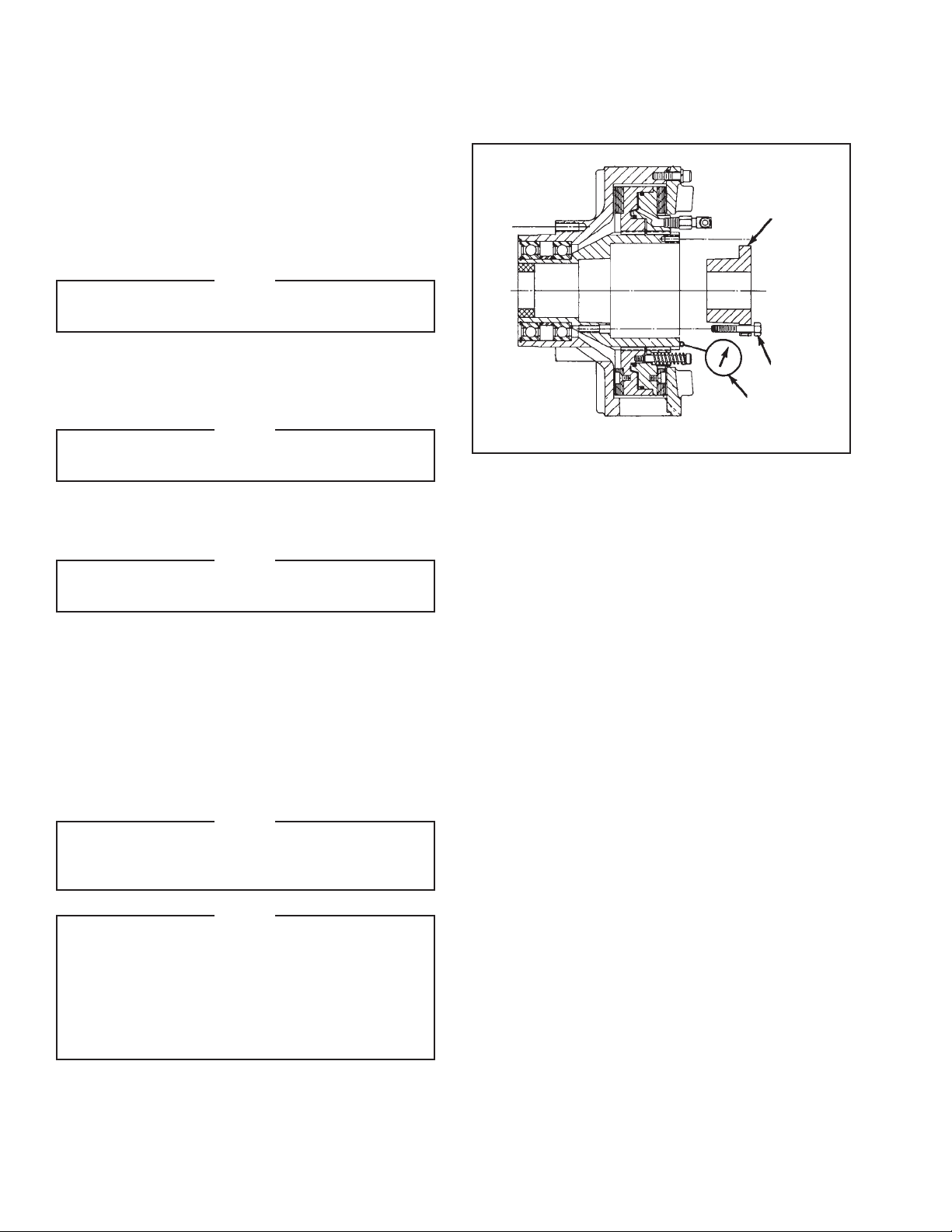
PILOT MOUNT CLUTCH
REFER TO FIGURE 2.
1. Install Support Bushing if required.
2. Thoroughly inspect tapered bore of the Splined Hub
and tapered surface of the Q. D. Bushing. Remove
any dirt, grease, or foreign material.
NOTE
Do not use lubricants when installing the Q.D.
Bushing.
3. Install Q. D. Bushing into Splined Hub, aligning
untapped holes on Q. D. Bushing Flange with
tapped holes in Splined Hub.
NOTE
Do not strike Q. D. Bushing to “SET” it in the
tapered bore.
4. Loosely insert Pull-Up Bolts and Lockwashers into
Q. D. Bushing, and tapped holes of Splined Hub.
NOTE
Do not use lubricants or thread locking
compounds on Pull-Up Bolts.
5. Measure runout of Motor Shaft. Runout must not
exceed 0.002 T.I.R. (Total Indicator Reading)
Q.D. Bushing
Pull-Up
Bolts
Dial
Indicator
FIGURE 2
6. Insert Key into Motor Shaft Keyway.
7. Slide “DPC” Clutch onto Motor Shaft.
8. Alternately, and evenly tighten Pull-Up Bolts to
recommended torque (See Table 1).
NOTE
Do not over tighten Pull-Up Bolts. If excessive
tightening torque is applied, bursting pressure
is created in the Splined Hub.
NOTE
Runout is minimized if a Dial Indicator is
used as the Q. D. Bushing Pull-Up Bolts are
tightened. Place contact tip of Dial Indicator
on the machined surface of the Splined Hub to
measure runout. Runout on this surface must
be within 0.003 T.I.R. when the Pull-Up Bolts
are tightened.
FORM NO. L-20070-F-1209
3
Page 7
INSTALLATION (continued)
SHEAVE MOUNT
NOTE
The Sheave Clutch is a combination of the Pilot
Clutch and Sheave Assembly (both shipped in
a separate container).
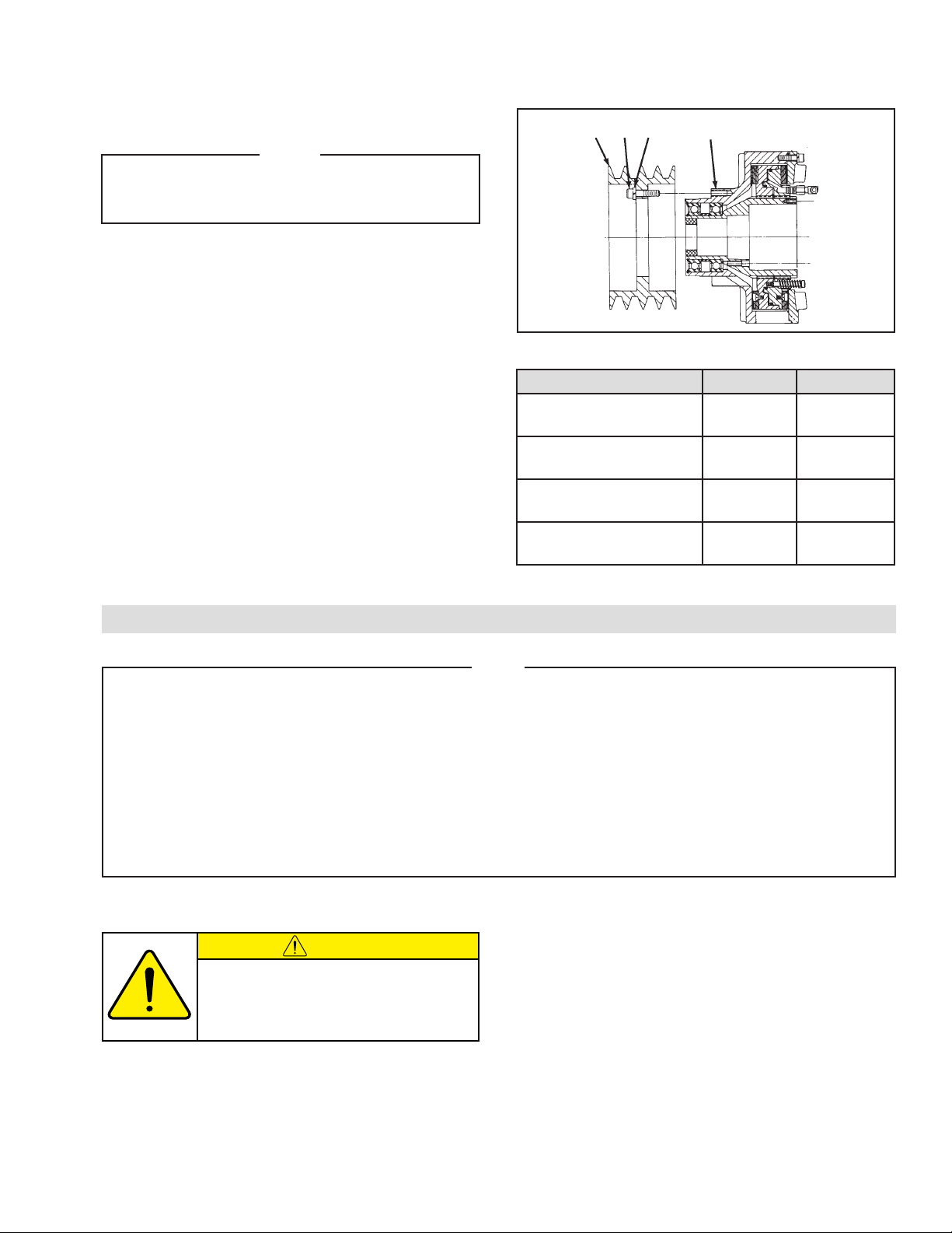
REFER TO FIGURE 3.
1. Slide the Sheave (Item 26) onto the pilot diameter of
the Pilot Clutch Assembly.
2. Align the mounting holes in the Sheave (Item 26)
with the tapped holes in the Housing (Item 5).
3. Install the Cap Screws (Item 28), and Lockwashers
(Item 27).
4. Tighten the Cap Screws (Item 28) to the
recommended torque (See Table 2).
5. Proceed with Steps 1 through 8 from Pilot Mount
Clutch Installation section on the previous page.
26
28
27
5
FIGURE 3
TABLE 2 Recommended Tightening Torques
Description DPC-9T DPC-11T
Shoulder Screw (Item 12)
Cap Screw (Item 15)
Cap Screw (Item 24)
Cap Screw (Item 28)
9 ft-lbs
[12 Nm]
48 ft-lbs
[65 Nm]
13 ft-lbs
[18 Nm]
48 ft-lbs
[65 Nm]
9 ft-lbs
[12 Nm]
48 ft-lbs
[65 Nm]
13 ft-lbs
[18 Nm]
48 ft-lbs
[65 Nm]
LUBRICATION
Nexen pneumatically actuated devices require clean, pressure regulated air for maximum performance and
life. All seals in Nexen pneumatically operated devices are lubricated for life, and do not require additional
lubrication.
However, some customers prefer to use an air line lubricator, which injects oil into the pressurized air,
forcing an oil mist into the air chamber. This is acceptable, but care must be taken to ensure once an air
mist lubrication system is used, it is continually used over the life of the product as the oil mist may wash
free the factory installed lubrication.
Locate the lubricator above and within ten feet of the product, and use low viscosity oil such as SAE-10.
Synthetic lubricants are not recommended.
Nexen product's bearings are shielded and pre-lubricated, and require no further lubrication.
LUBRICATOR DRIP RATE SETTINGS
CAUTION
These settings are for Nexen supplied
lubricators. If you are not using a Nexen
lubricator, calibration must follow the
manufacturer's suggested procedure.
1. Close and disconnect the air line from the unit.
NOTE
4. Close the air line to the unit when a drop of oil forms
in the Lubricator Sight Gage.
5. Connect the air line to the unit.
6. Turn the Lubricator Adjustment Knob clockwise until
closed.
2. Turn the Lubricator Adjustment Knob
counterclockwise three complete turns.
3. Open the air line.
7. Turn the Lubricator Adjustment Knob
counterclockwise one-third turn.
8. Open the air line to the unit.
4
FORM NO. L-20070-F-1209
Page 8
AIR CONNECTIONS
All Nexen pneumatically actuated devices require clean and
dry air, which meets or exceeds ISO 8573.1:2001 Class
4.4.3 quality.
NOTE
For quick response, Nexen recommends a quick
exhaust valve and short air lines between the
Control Valves and the unit. Align the air inlet
ports to a down position to allow condensation
to drain out of the air chambers of the product.
CAUTION
Low air pressure will cause slippage and
overheating. Excessive air pressure will
cause abrupt starts and stops, reducing
product life.
SHAFT END MOUNTING
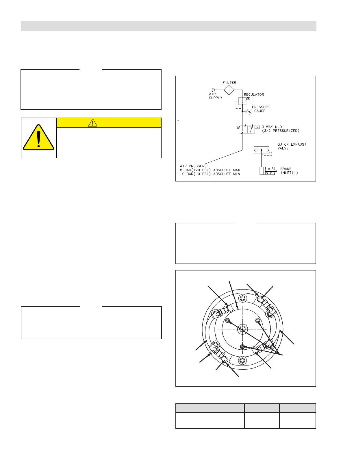
The following are common air supply schemes used with
this product. These are examples and not an all-inclusive
list. All air circuits to be used with this product must be
designed following EN983 guidelines.
REFER TO FIGURE 4.
1. Install two Elbow Fittings (Item 20) into the Rotary
Air Union Cap (Item 25).
2. Install an Adaptor Fitting (Item 19) and Elbow Fitting
(Item 20) into each air inlet of the Piston/Drive Disc
(Item 2).
3. Using Cap Screws (Item 24), attach the Rotary
Air Union Cap (Item 25) to the tapped holes of the
Splined Hub (Item 1).
NOTE
The Rotary Air Union Cap air outlets must be
aligned at approximately 60O to the Piston/
Drive Disc air inlets for proper Hose (Item 22)
connection.
4. Tighten the Cap Screws (Item 24) to the
recommended torque (See Table 3).
5. Install Hoses (Item 22).
6. Install the Rotary Air Union (Item 21).
NOTE
Do not use rigid pipe or tubing for this connection.
For fast engagement and disengagement,
connect air controls as close to the DPC Clutch
as possible. Where long air lines are required,
use a quick exhaust valve.
20
25
22
2
20
FIGURE 4
19
19
20
24
20
22
7. Connect air supply to the Rotary Air Union.
FORM NO. L-20070-F-1209
TABLE 3 Recommended Tightening Torques
Description DPC-9T DPC-11T
Cap Screw (Item 24)
13 ft-lbs
[18 Nm]
5
13 ft-lbs
[18 Nm]
Page 9
AIR CONNECTIONS (continued)
THROUGH SHAFT MOUNTING
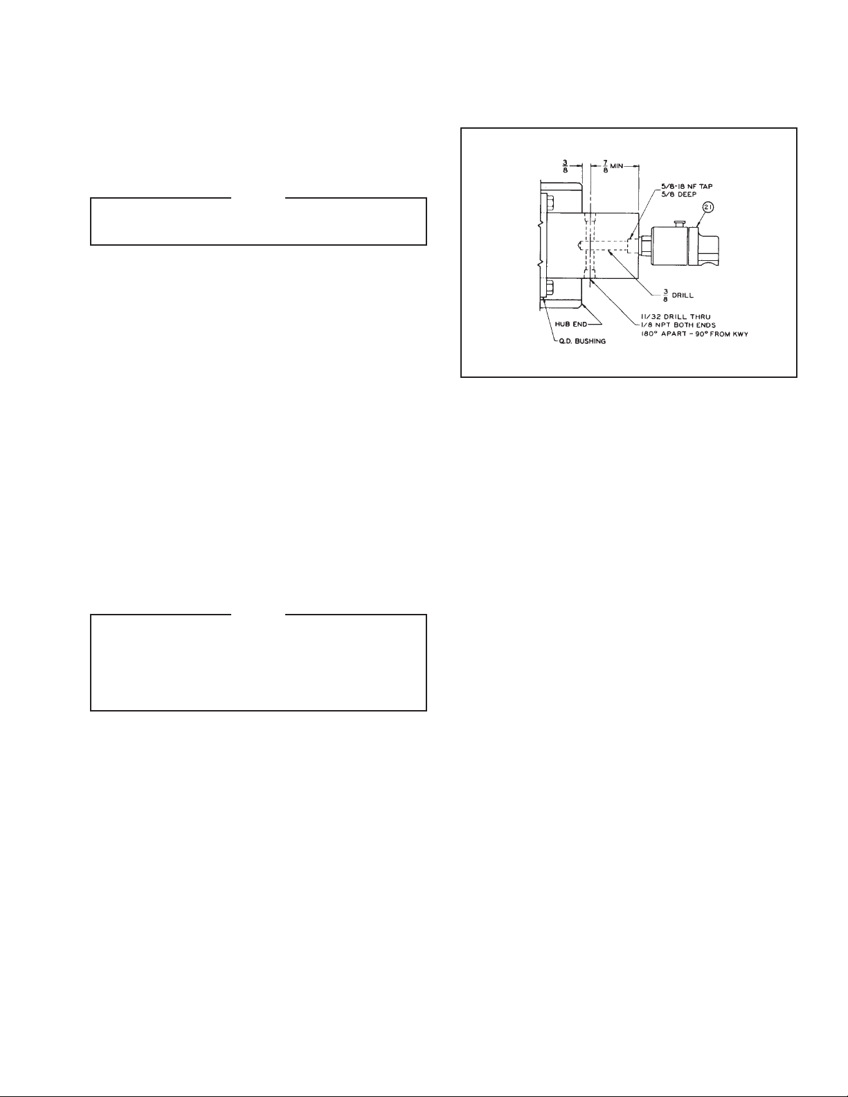
REFER TO FIGURE 5.
1. Drill a 3/8" diameter hole into the center of the shaft;
deep enough to reach the desired air outlets.
NOTE
Air outlets should be approximately 3/8" from
the end of the Hub.
2. Tap the end of the Shaft 5/8–18 by 5/8" deep.
3. Drill a 11/32" diameter air outlet hole through the
shaft; intersecting the air inlet hole approximately
3/8" from the end of the Hub.
4. Tap both air outlet holes 1/8–27 NPT by 5/8" deep.
5. Install two Elbow Fittings (Item 20) into each air
outlet hole.
6. Install an Adaptor Fitting (Item 19) and Elbow Fitting
(Item 20) into each air inlet of the Piston/Drive Disc
(Item 2).
7. Install Hoses (Item 22).
8. Install the Rotary Air Union (Item 21).
9. Connect air supply to the Rotary Air Union.
NOTE
Do not use rigid pipe or tubing for this connection.
For fast engagement and disengagement,
connect air controls as close to the “DPC” Clutch
as possible. Where long air lines are required,
use a quick exhaust valve.
FIGURE 5
6
FORM NO. L-20070-F-1209
Page 10
OPERATION
CAUTION
WARNING
The temperature limits for this product line
are 4.5º - 104º C (40º-220º F).
CAUTION
Never exceed life of facing material. Facing
life depends on the volume of material and
the total energy over the life of the unit.
Expected life (in hrs) can be found by:
Volume
Time=
/
(Power • Wear Rate)
CAUTION
Before placing the DPC Clutch into
service; verify that all screws are secured
to the proper torque (See Table 4).
The “DPC” Clutch engages when air pressure is introduced
into the Cylinder/Drive Disc. Air pressure pushes the
Cylinder/Drive Disc against the Flange Mount Disc, and
forces the Cylinder/Drive Disc in the opposite direction.
This engages the Friction Facings with the friction surfaces
of the Flange Mount Disc and the Friction Disc.
Torque is transmitted through the Cylinder/Drive Disc, and
Piston/Drive Disc Splines to the Splined Hub attached to
the Shaft with a Q.D. Bushing.
Heat generated at the friction surfaces is dissipated by
windage created by the fins on the Flange Mount Disc,
and the Friction Disc.
Never exceed maximum operating speeds
listed for your product (See Table 5).
WARNING
Ensure proper guarding of the product is
used. Nexen recommends the machine
builder design guarding in compliance
with OSHA 29 CFR 1910 “Occupational Safety and Health Hazards.”
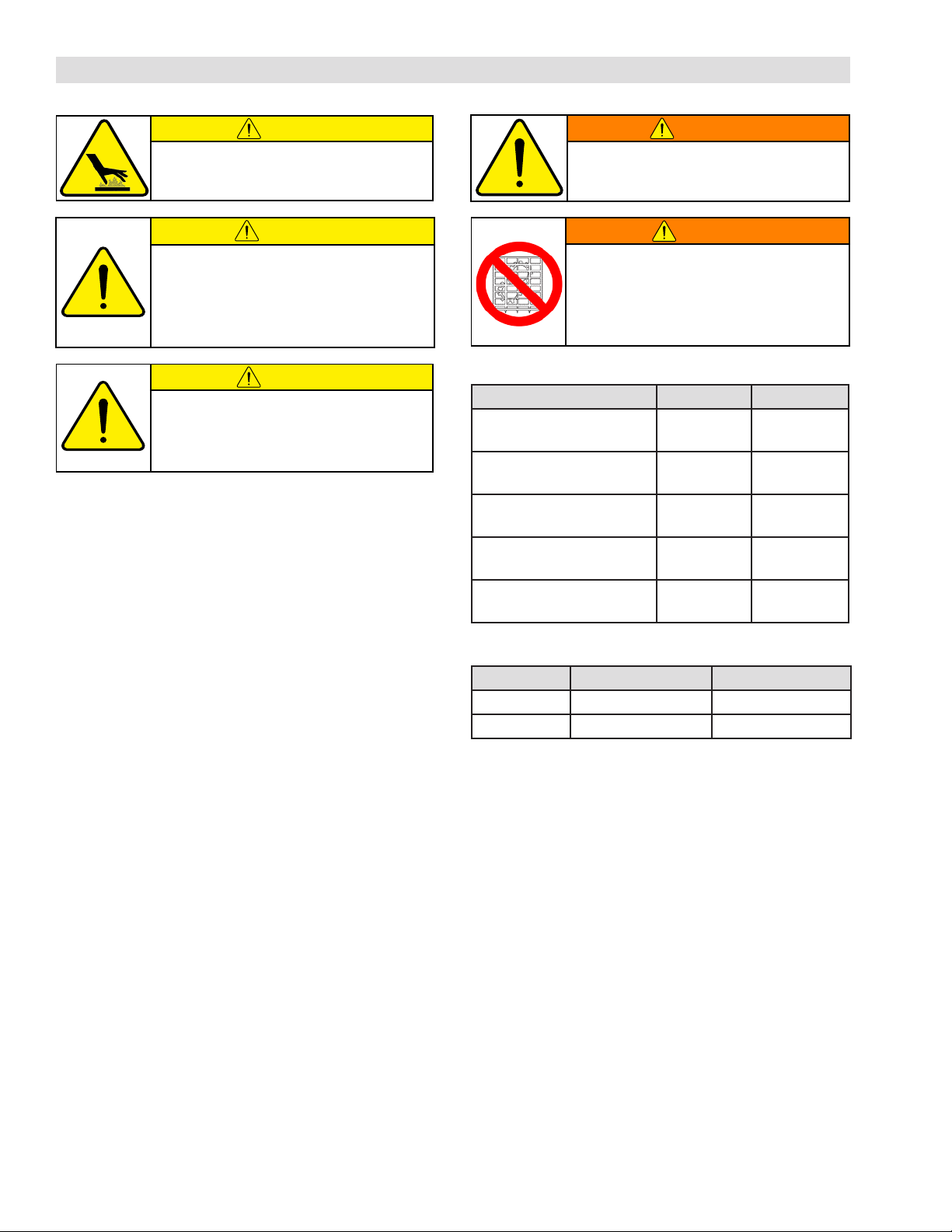
TABLE 4 Recommended Tightening Torques
Description DPC-9T DPC-11T
Shoulder Screw (Item 12)
Cap Screw (Item 15)
Cap Screw (Item 24)
Cap Screw (Item 28)
Pull-up Bolts
TABLE 5 Maximum Allowable Speed
Model Outer Assembly Inner Assembly
DPC-9T 2200 RPM 3000 RPM
DPC-11T 1800 RPM 2500 RPM
9 ft-lbs
[12 Nm]
48 ft-lbs
[65 Nm]
13 ft-lbs
[18 Nm]
48 ft-lbs
[65 Nm]
15 ft-lbs
[20 Nm]
9 ft-lbs
[12 Nm]
48 ft-lbs
[65 Nm]
13 ft-lbs
[18 Nm]
48 ft-lbs
[65 Nm]
30 ft-lbs
[41 Nm]
When air is exhausted from the Cylinder, Return Springs
pull the Piston to disengaged position.
FORM NO. L-20070-F-1209
7
Page 11
PARTS REPLACEMENT
CAUTION
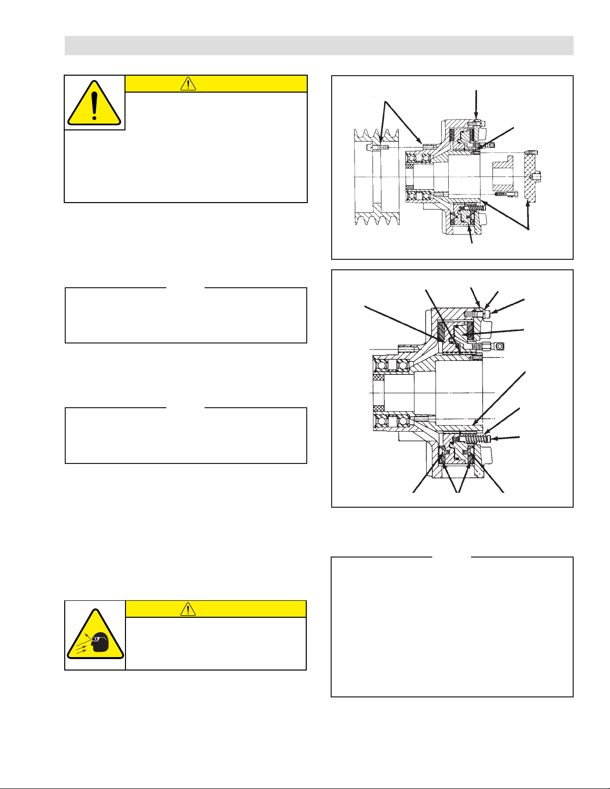
The Nexen DPC Clutch has been balanced
at the factory. During disassembly, mark
components with chalk alignment marks to
insure correct alignment and balance as the DPC Clutch
is reassembled (See Figure 6).
When reassembling the Nexen DPC Clutch, make sure all
screws are tightened to the recommended torque (See
Table 4 in OPERATIONS SECTION).
FRICTION FACING (ITEM 4)
NOTE
Inspect Friction Facings for wear, and replace
when they are appropriately 9/32" thick. Friction
Facings can be replaced without removing the
DPC Clutch from the motor shaft.
REFER TO FIGURE 7.
1. Disconnect the air supply and Hose Assemblies at
the Piston/Drive Disc Elbow Fittings.
Alignment
FIGURE 6
3
Mark
10
Alignment Mark
Alignment Mark
6
14
Alignment
Mark
Alignment
Mark
15
2
1
NOTE
If the “DPC” Clutch is shaft end mounted; remove
the Rotary Air Union Cap (Item 25). On through
shaft installation; remove the Elbow Fittings
(Item 20) from the shaft.
2. Remove Cap Screws (Item 15) and Lockwashers
(Item 14).
3. Remove the Friction Disc (Item 6).
4. Remove Shoulder Screws (Item 12) and Springs
(Item 13).
5. Slide the Piston/Drive Disc (Item 2) off of the Splined
Hub (Item 1).
CAUTION
Working with spring loaded or tension
loaded fasteners and devices can cause
injury. Wear safety glasses and take the
appropriate safety precautions.
6. Remove the Retaining Ring (Item 10).
13
12
FIGURE 7
11
4
11
8. Remove the Machine Screws (Item 11), and replace
worn Friction Facings (Item 4).
NOTE
On some models of the DPC-9T and DPC-11T,
the Machine Screws (Item 11) are assembled
wit h a g reen anaero bic thread lock ing
compound. If remove is difficult, strike the end
of the screwdriver with a hammer to break the
crystalline structure of this locking compound
before attempting to remove the screws. The
Machine Screws (Item 11) that are furnished
with new Friction Facings have a locking patch,
and do not require the use of a thread locking
compound.
7. Slide the Cylinder/Drive Disc (Item 3) off of the
Splined Hub (Item 1).
9. Reverse Steps 1 through 7 to reassemble the DPC
Clutch, noting chalk alignment marks and tighten all
screws to the recommended torque (See Table 4).
8
FORM NO. L-20070-F-1209
Page 12
PARTS REPLACEMENT (continued)
O-RINGS (ITEMS 8 & 9)
NOTE
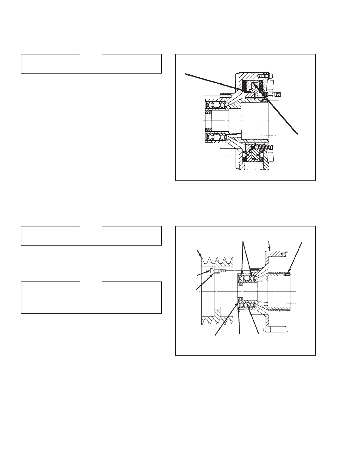
Replace O-rings (Items 8 & 9) if there are
noticeable air leaks, or a loss of torque.
REFER TO FIGURE 8.
1. Proceed with Steps 1 through 7 for the Friction
Facing Replacement.
2. Remove O-rings (Items 8 & 9), and clean o-ring
contact surfaces with fresh safety solvent.
3. Lubricate new O-rings, and o-ring contact surfaces
with fresh o-ring lubricant.
4. Install new O-rings (Items 8 & 9).
5. Reverse Step 1 to reassemble the DPC Clutchnoting chalk alignment marks- and tighten all screws
to the recommended torque (See Table 4).
9
8
FIGURE 8
BEARINGS (ITEM 16)
NOTE
DPC Clutch Bearings are pre-lubricated, sealed,
and do not require further lubrication.
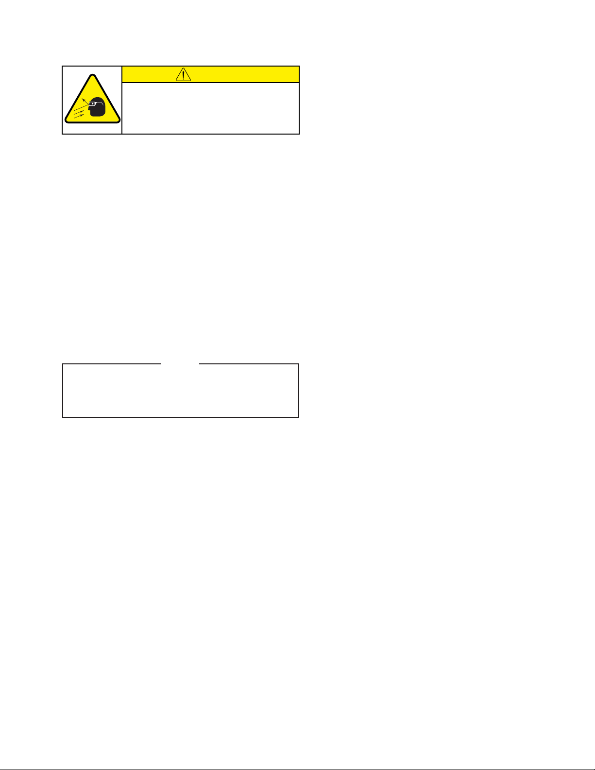
REFER TO FIGURE 9.
1. Disconnect the air supply line, and Hose Assemblies
at the Piston/Drive Disc Elbow Fittings.
NOTE
If the DPC Clutch is shaft mounted, remove
the Rotary Air Union Cap (Item 25). On through
shaft installation, remove the Elbow Fittings
(Item 20) from the shaft.
2. Loosen the Q.D. Bushing by first removing the Q.D.
Bushing Pull-Up Bolts and Lockwashers. Then insert
Pull-Up Bolts into tapped Q.D. Bushing removal
holes and alternately and evenly tighten each until the
Splined Hub (Item 1) is loose on the Q.D. Bushing.
3. Wedge a screwdriver into the saw-cut in the Q.D.
Bushing to loosen the Q.D. Bushing from the Shaft;
then remove the “DPC” Clutch.
26
28
27
FIGURE 9
17 18
16
5
7
1
4. Remove Cap Screws (Item 28), and Lockwashers
(Item 27), and Sheave (Item 26) in mounted on the
DPC Clutch.
5. Proceed with steps 1 through 7 for the Friction
Facing replacement.
FORM NO. L-20070-F-1209
9
Page 13
BEARING PARTS REPLACEMENT (continued)
CAUTION
Working with spring loaded or tension
loaded fasteners and devices can cause
injury. Wear safety glasses and take the
appropriate safety precautions.
REFER TO FIGURE 9.
6. Remove Retaining Ring (Item 17).
7. Fully supporting the Housing (Item 5); press the Hub
(Item 1), out of the Housing and Bearings.
8. Remove Retaining Ring (Item 18).
9. Fully supporting the Housing (Item 5); push the
Bearing (Item 16), and Spacer (Item 17), out of the
Housing.
10. Clean bearing contact surfaces of both Housing
(Item 5), and Hub (Item 1) with fresh safety solvent.
11. Press new Bearings (Item 16), and Spacer (Item 7
into the Housing (Item 5).
NOTE
When installing new Bearings; carefully align
the Bearing O.D. with the Housing bore. Apply
Loctite
®
RC 601 or equivalent to the outer race
of the new Bearings.
12. Install Retaining Ring (Item 18).
13. Fully supporting the inner race of the new Bearings;
press the Hub (Item 1) into the Bearings, and
Housing.
14. Install Retaining Ring (Item 17).
15. Reverse Steps 1 through 5 to reassemble the DPC
Clutch. Be sure to note the chalk alignment marks
and tighten all screws to the recommended torque
(See Table 4).
10
FORM NO. L-20070-F-1209
Page 14
REPLACEMENT PARTS LIST
17
18
16
16
7
5
1
11
4
3
8
9
10
2
4
11
6
13
20
22
24
25
21
14
19
12
15
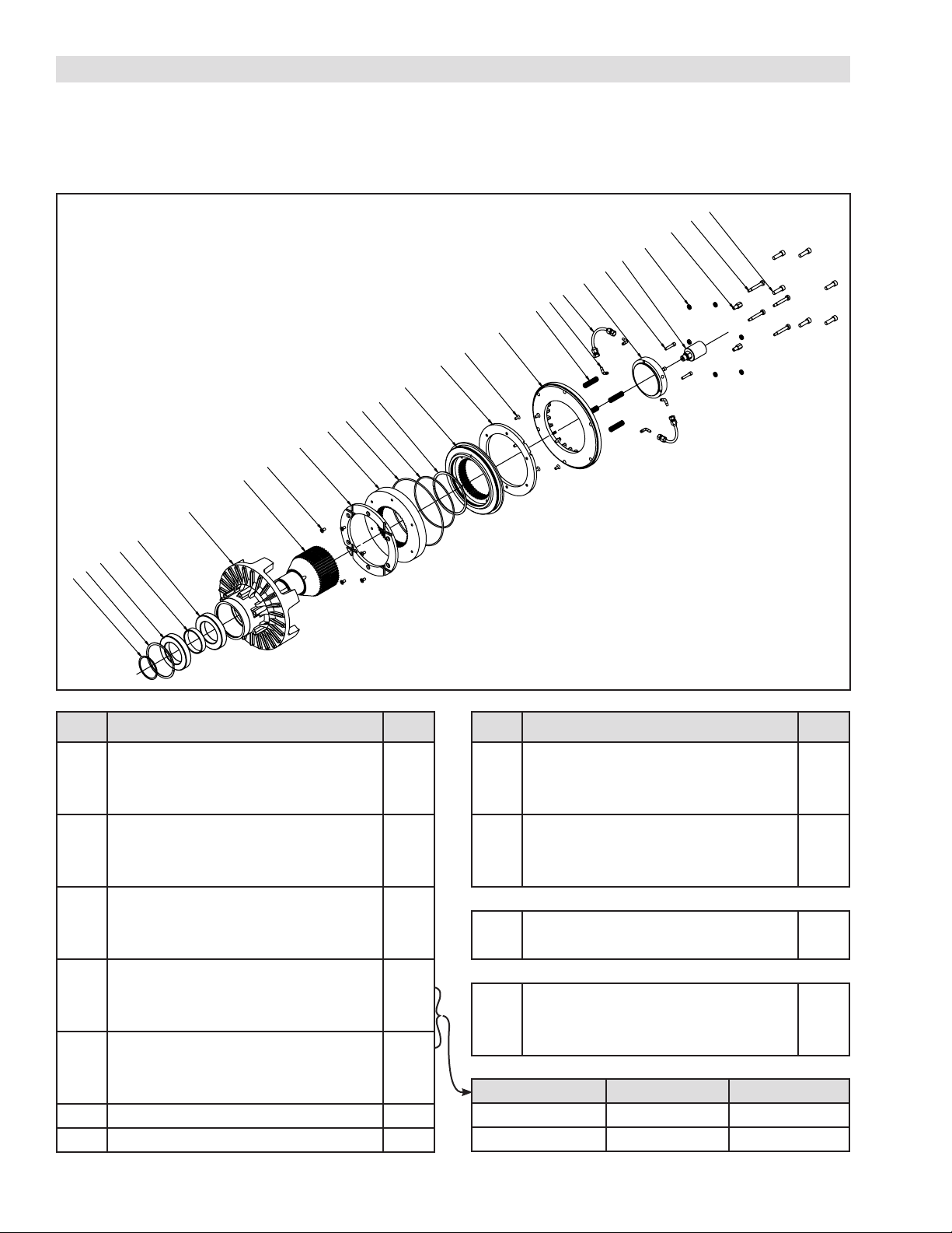
The item or balloon number for all Nexen products is used
for part identification on all product parts lists, product
price lists, unit assembly drawings, bills of materials, and
instruction manuals.
When ordering replacement parts, specify model designation, item number, part description, and quantity. Purchase
replacement parts through your local Nexen Distributor.
ITEM DESCRIPTION QTY
1 Hub 1
2 Piston/Drive Disc 1
3 Cylinder/Drive Disc 1
4 Friction Facing 2
5 Housing 1
6
Friction Disc 1
7 Spacer 1
8 O-ring Seal (large) 1
9 O-ring Seal (small) 1
10 Retaining Ring 1
11 Machine Screw *
12 Shoulder Screw **
13 Spring **
14 Lockwasher 6
15 Cap Screw 6
16 Bearing 2
17 Retaining Ring 1
ITEM DESCRIPTION QTY
18 Retaining Ring 1
19 Adapter Fitting 2
20 Elbow Fitting 4
21 Rotary Air Union 1
22 Hose Assembly (not shown) 2
23 Hose Assembly (not shown) 1
Rotary Air Union Cap
24 Rotary Air Union Cap 1
25 Cap Screw 3
Sheave
26 Sheave 1
27 Lock Washer 6
28 Cap Screw 6
MODEL * QTY ** QTY
DPC-9T 12 1
DPC-11T 16 4
FORM NO. L-20070-F-1209
11
Page 15

Nexen Group, Inc.
560 Oak Grove Parkway
Vadnais Heights, MN 55127
800.843.7445
Fax: 651.286.1099
www.nexengroup.com
ISO 9001 Certified
WARRANTY
Warranties
Nexen warrants that the Products will (a) be free from any defects in material or workmanship for a period of 12 months
from the date of shipment, and (b) will meet and perform in accordance with the specifications in any engineering drawing
specifically for the Product that is in Nexen’s current product catalogue, or that is accessible at the Nexen website, or that is
attached to this Quotation and that specifically refers to this Quotation by its number, subject in all cases to any limitations
and exclusions set out in the drawing. NEXEN MAKES NO OTHER WARRANTY, EXPRESS OR IMPLIED, AND ALL
IMPLIED WARRANTIES, INCLUDING WITHOUT LIMITATION, IMPLIED WARRANTIES OF MERCHANTABILITY AND
FITNESS FOR A PARTICULAR PURPOSE ARE HEREBY DISCLAIMED. This warranty applies only if: (a) the Product has
been installed, used and maintained in accordance with any applicable Nexen installation or maintenance manual for the
Product; (b) the alleged defect is not attributable to normal wear and tear; (c) the Product has not been altered, misused or
used for purposes other than those for which it was intended; and (d) Buyer has given written notice of the alleged defect
to Nexen, and delivered the allegedly defective Product to Nexen, within one year of the date of shipment.
Exclusive Remedy
The exclusive remedy for the Buyer for any breach of any warranties provided in connection with this agreement will be,
at the election of Nexen: (a) repair or replacement with new, serviceably used, or reconditioned parts or products; or (b)
issuance of credit in the amount of the purchase price paid to Nexen by the Buyer for the Products.
Agent's Authority
Buyer agrees that no agent, employee or representative of Nexen has authority to bind Nexen to any affirmation, representation,
or warranty concerning the Products other than those warranties expressly set forth herein.
Limitation on Nexen’s Liability
TO THE EXTENT PERMITTED BY LAW NEXEN SHALL HAVE NO LIABILITY TO BUYER OR ANY OTHER PERSON
FOR INCIDENTAL DAMAGES, SPECIAL DAMAGES, CONSEQUENTIAL DAMAGES OR OTHER DAMAGES OF ANY
KIND OR NATURE WHATSOEVER, WHETHER ARISING OUT OF BREACH OF WARRANTY OR OTHER BREACH
OF CONTRACT, NEGLIGENCE OR OTHER TORT, OR OTHERWISE, EVEN IF NEXEN SHALL HAVE BEEN ADVISED
OF THE POSSIBILITY OR LIKELIHOOD OF SUCH POTENTIAL LOSS OR DAMAGE. For all of the purposes hereof, the
term "consequential damages" shall include lost profits, penalties, delay damages, liquidated damages or other damages
and liabilities which Buyer shall be obligated to pay or which Buyer may incur based upon, related to or arising out of its
contracts with its customers or other third parties. In no event shall Nexen be liable for any amount of damages in excess of
amounts paid by Buyer for Products or services as to which a breach of contract has been determined to exist. The parties
expressly agree that the price for the Products and the services was determined in consideration of the limitation on damages
set forth herein and such limitation has been specifically bargained for and constitutes an agreed allocation of risk which
shall survive the determination of any court of competent jurisdiction that any remedy herein fails of its essential purpose.
Inspection
Buyer shall inspect all shipments of Products upon arrival and shall notify Nexen in writing, of any shortages or other failures
to conform to these terms and conditions which are reasonably discoverable upon arrival without opening any carton or
box in which the Products are contained. Such notice shall be sent within 14 days following arrival. All notifications shall be
accompanied by packing slips, inspection reports and other documents necessary to support Buyer's claims. In addition
to the foregoing obligations, in the event that Buyer receives Products that Buyer did not order, Buyer shall return the
erroneously shipped Products to Nexen within thirty (30) days of the date of the invoice for such Products; Nexen will pay
reasonable freight charges for the timely return of the erroneously shipped Products, and issue a credit to Buyer for the
returned Products at the price Buyer paid for them, including any shipping expenses that Nexen charged Buyer. All shortages,
overages and nonconformities not reported to Nexen as required by this section will be deemed waived.
Limitation on Actions
No action, regardless of form, arising out of any transaction to which these terms and conditions are applicable may be
brought by the Buyer more than one year after the cause of action has accrued.
12
FORM NO. L-20070-F-1209
 Loading...