

Page 1

NEXCOM International Co., Ltd.
Network and Communication Solutions
Network Security Appliance
NSA 5170C
User Manual
NEXCOM International Co., Ltd.
Published May 2019
www.nexcom.com
Page 2

Content
Contents
Preface
Copyright ............................................................................................. iv
Disclaimer .............................................................................................. iv
Acknowledgements ............................................................................... iv
Regulatory Compliance Statements ........................................................ iv
Declaration of Conformity ...................................................................... iv
RoHS Compliance ................................................................................... v
Warranty and RMA ................................................................................ vi
Safety Information ................................................................................viii
Installation Recommendations ...............................................................viii
Safety Precautions .................................................................................. ix
Technical Support and Assistance ............................................................ x
Conventions Used in this Manual ............................................................ x
Global Service Contact Information ........................................................ xi
Package Contents ................................................................................. xiii
Ordering Information ............................................................................xiv
Chapter 1: Product Introduction
Overview ................................................................................................1
Key Features ...........................................................................................1
Hardware Specifications ..........................................................................2
Knowing Your NSA 5170C ...................................................................... 3
Front Panel ..........................................................................................3
Rear Panel ...........................................................................................4
Chapter 2: Jumpers and Connectors
Before You Begin ....................................................................................5
Precautions ............................................................................................5
Jumper Settings ......................................................................................6
Locations of the Jumpers and Connectors ............................................... 7
Jumpers .................................................................................................. 8
CMOS Clear Jumper ............................................................................ 8
Connector Pin Definitions .......................................................................9
Internal Connectors ............................................................................. 9
System Reset Header ........................................................................ 9
COM1 Header ..................................................................................9
Fan Connectors .............................................................................. 10
VGA Connector .............................................................................10
8-pin Internal Power Connector .....................................................11
24-pin Internal Power Connector ...................................................11
Rear USB 2.0 Connector .................................................................12
Power Button ................................................................................. 12
GPIO Pin Header ............................................................................13
TPM Header ................................................................................... 13
LCM ...............................................................................................14
Block Diagram ......................................................................................15
Chapter 3: System Setup
Installing a CompactFlash (CF) Card ......................................................16
Copyright © 2018 NEXCOM International Co., Ltd. All Rights Reserved.
ii
NSA 5170C User Manual
Page 3

Content
Installing a CPU .....................................................................................17
Installing DIMM Memory Modules ........................................................20
Installing a 2.5” SATA Hard Drive ..........................................................21
Installing a LAN Module ........................................................................ 22
Connecting the Power Switch (Optional) ............................................... 24
Chapter 4: BIOS Setup
About BIOS Setup ................................................................................. 25
When to Configure the BIOS .................................................................25
Default Configuration ........................................................................... 26
Entering Setup ...................................................................................... 26
Legends ................................................................................................ 26
BIOS Setup Utility .................................................................................. 28
Main .................................................................................................28
Advanced ......................................................................................... 29
Chipset ..............................................................................................40
Boot .................................................................................................. 45
Save & Exit ........................................................................................46
Copyright © 2018 NEXCOM International Co., Ltd. All Rights Reserved.
iii
NSA 5170C User Manual
Page 4

Preface
PrefaCe
Copyright
This publication, including all photographs, illustrations and software, is
protected under international copyright laws, with all rights reserved. No
part of this manual may be reproduced, copied, translated or transmitted in
any form or by any means without the prior written consent from NEXCOM
International Co., Ltd.
Disclaimer
The information in this document is subject to change without prior notice and
does not represent commitment from NEXCOM International Co., Ltd. However,
users may update their knowledge of any product in use by constantly checking
its manual posted on our website: http://www.nexcom.com. NEXCOM shall
not be liable for direct, indirect, special, incidental, or consequential damages
arising out of the use of any product, nor for any infringements upon the rights
of third parties, which may result from such use. Any implied warranties of
merchantability or fitness for any particular purpose is also disclaimed.
Acknowledgements
NSA 5170C is a trademark of NEXCOM International Co., Ltd. All other product
names mentioned herein are registered trademarks of their respective owners.
Regulatory Compliance Statements
This section provides the FCC compliance statement for Class A devices and
describes how to keep the system CE compliant.
Declaration of Conformity
FCC
This equipment has been tested and verified to comply with the limits for
a Class A digital device, pursuant to Part 15 of FCC Rules. These limits are
designed to provide reasonable protection against harmful interference when
the equipment is operated in a commercial environment. This equipment
generates, uses, and can radiate radio frequency energy and, if not installed
and used in accordance with the instructions, may cause harmful interference
to radio communications. Operation of this equipment in a residential area
(domestic environment) is likely to cause harmful interference, in which
case the user will be required to correct the interference (take adequate
measures) at their own expense.
CE
The product(s) described in this manual complies with all applicable
European Union (CE) directives if it has a CE marking. For computer systems
to remain CE compliant, only CE-compliant parts may be used. Maintaining
CE compliance also requires proper cable and cabling techniques.
Copyright © 2018 NEXCOM International Co., Ltd. All Rights Reserved.
iv
NSA 5170C User Manual
Page 5

Preface
RoHS Compliance
NEXCOM RoHS Environmental Policy and Status
Update
NEXCOM is a global citizen for building the digital
infrastructure. We are committed to providing green
products and services, which are compliant with
European Union RoHS (Restriction on Use of Hazardous Substance in
Electronic Equipment) directive 2011/65/EU, to be your trusted green
partner and to protect our environment.
RoHS restricts the use of Lead (Pb) < 0.1% or 1,000ppm, Mercury (Hg)
< 0.1% or 1,000ppm, Cadmium (Cd) < 0.01% or 100ppm, Hexavalent
Chromium (Cr6+) < 0.1% or 1,000ppm, Polybrominated biphenyls (PBB) <
0.1% or 1,000ppm, and Polybrominated diphenyl Ethers (PBDE) < 0.1% or
1,000ppm.
In order to meet the RoHS compliant directives, NEXCOM has established an
engineering and manufacturing task force in to implement the introduction
of green products. The task force will ensure that we follow the standard
NEXCOM development procedure and that all the new RoHS components
and new manufacturing processes maintain the highest industry quality
levels for which NEXCOM are renowned.
The model selection criteria will be based on market demand. Vendors and
suppliers will ensure that all designed components will be RoHS compliant.
How to recognize NEXCOM RoHS Products?
For existing products where there are non-RoHS and RoHS versions, the
suffix “(LF)” will be added to the compliant product name.
All new product models launched after January 2013 will be RoHS compliant.
They will use the usual NEXCOM naming convention.
Copyright © 2018 NEXCOM International Co., Ltd. All Rights Reserved.
v
NSA 5170C User Manual
Page 6

Preface
Warranty and RMA
NEXCOM Warranty Period
NEXCOM manufactures products that are new or equivalent to new in
accordance with industry standard. NEXCOM warrants that products will
be free from defect in material and workmanship for 2 years, beginning on
the date of invoice by NEXCOM. HCP series products (Blade Server) which
are manufactured by NEXCOM are covered by a three year warranty period.
NEXCOM Return Merchandise Authorization (RMA)
▪ Customers shall enclose the “NEXCOM RMA Service Form” with the
returned packages.
▪ Customers must collect all the information about the problems
encountered and note anything abnormal or, print out any on-screen
messages, and describe the problems on the “NEXCOM RMA Service
Form” for the RMA number apply process.
▪ Customers can send back the faulty products with or without accessories
(manuals, cable, etc.) and any components from the card, such as CPU
and RAM. If the components were suspected as part of the problems,
please note clearly which components are included. Otherwise, NEXCOM
is not responsible for the devices/parts.
▪ Customers are responsible for the safe packaging of defective products,
making sure it is durable enough to be resistant against further damage
and deterioration during transportation. In case of damages occurred
during transportation, the repair is treated as “Out of Warranty.”
▪ Any products returned by NEXCOM to other locations besides the
customers’ site will bear an extra charge and will be billed to the customer.
Repair Service Charges for Out-of-Warranty Products
NEXCOM will charge for out-of-warranty products in two categories, one is
basic diagnostic fee and another is component (product) fee.
Repair Service Charges for Out-of-Warranty Products
NEXCOM will charge for out-of-warranty products in two categories, one is
basic diagnostic fee and another is component (product) fee.
System Level
▪ Component fee: NEXCOM will only charge for main components such as
SMD chip, BGA chip, etc. Passive components will be repaired for free,
ex: resistor, capacitor.
▪ Items will be replaced with NEXCOM products if the original one cannot
be repaired. Ex: motherboard, power supply, etc.
▪ Replace with 3rd party products if needed.
▪ If RMA goods can not be repaired, NEXCOM will return it to the customer
without any charge.
Board Level
▪ Component fee: NEXCOM will only charge for main components, such
as SMD chip, BGA chip, etc. Passive components will be repaired for free,
ex: resistors, capacitors.
▪ If RMA goods can not be repaired, NEXCOM will return it to the customer
without any charge.
Copyright © 2018 NEXCOM International Co., Ltd. All Rights Reserved.
vi
NSA 5170C User Manual
Page 7

Preface
Warnings
Read and adhere to all warnings, cautions, and notices in this guide and
the documentation supplied with the chassis, power supply, and accessory
modules. If the instructions for the chassis and power supply are inconsistent
with these instructions or the instructions for accessory modules, contact
the supplier to find out how you can ensure that your computer meets
safety and regulatory requirements.
Cautions
Electrostatic discharge (ESD) can damage system components. Do the
described procedures only at an ESD workstation. If no such station is
available, you can provide some ESD protection by wearing an antistatic
wrist strap and attaching it to a metal part of the computer chassis.
Copyright © 2018 NEXCOM International Co., Ltd. All Rights Reserved.
vii
NSA 5170C User Manual
Page 8

Preface
Safety Information
Before installing and using the device, note the following precautions:
▪ Read all instructions carefully.
▪ Do not place the unit on an unstable surface, cart, or stand.
▪ Follow all warnings and cautions in this manual.
▪ When replacing parts, ensure that your service technician uses parts
specified by the manufacturer.
▪ Avoid using the system near water, in direct sunlight, or near a heating
device.
▪ The load of the system unit does not solely rely for support from the
rackmounts located on the sides. Firm support from the bottom is highly
necessary in order to provide balance stability.
▪ The computer is provided with a battery-powered real-time clock circuit.
There is a danger of explosion if battery is incorrectly replaced. Replace
only with the same or equivalent type recommended by the manufacturer.
Discard used batteries according to the manufacturer’s instructions.
Installation Recommendations
Ensure you have a stable, clean working environment. Dust and dirt can get
into components and cause a malfunction. Use containers to keep small
components separated.
Adequate lighting and proper tools can prevent you from accidentally
damaging the internal components. Most of the procedures that follow
require only a few simple tools, including the following:
▪ A Philips screwdriver
▪ A flat-tipped screwdriver
▪ A grounding strap
▪ An anti-static pad
Using your fingers can disconnect most of the connections. It is recommended
that you do not use needle-nose pliers to disconnect connections as these
can damage the soft metal or plastic parts of the connectors.
Copyright © 2018 NEXCOM International Co., Ltd. All Rights Reserved.
viii
NSA 5170C User Manual
Page 9

Preface
Safety Precautions
1. Read these safety instructions carefully.
2. Keep this User Manual for later reference.
3. Disconnect this equipment from any AC outlet before cleaning. Use a
damp cloth. Do not use liquid or spray detergents for cleaning.
4. For plug-in equipment, the power outlet socket must be located near the
equipment and must be easily accessible.
5. Keep this equipment away from humidity.
6. Put this equipment on a stable surface during installation. Dropping it or
letting it fall may cause damage.
7. The openings on the enclosure are for air convection to protect the
equipment from overheating. DO NOT COVER THE OPENINGS.
8. Make sure the voltage of the power source is correct before connecting
the equipment to the power outlet.
9. Place the power cord in a way so that people will not step on it. Do not
place anything on top of the power cord. Use a power cord that has been
approved for use with the product and that it matches the voltage and
current marked on the product’s electrical range label. The voltage and
current rating of the cord must be greater than the voltage and current
rating marked on the product.
10. All cautions and warnings on the equipment should be noted.
11. If the equipment is not used for a long time, disconnect it from the
power source to avoid damage by transient overvoltage.
12. Never pour any liquid into an opening. This may cause fire or electrical
shock.
13. Never open the equipment. For safety reasons, the equipment should be
opened only by skilled person.
14. If one of the following situations arises, get the equipment checked by
service personnel:
a. The power cord or plug is damaged.
b. Liquid has penetrated into the equipment.
c. The equipment has been exposed to moisture.
d. The equipment does not work well, or you cannot get it to work
according to the user’s manual.
e. The equipment has been dropped and damaged.
f. The equipment has obvious signs of breakage.
15. Do not place heavy objects on the equipment.
16. The unit uses a three-wire ground cable which is equipped with a third
pin to ground the unit and prevent electric shock. Do not defeat the
purpose of this pin. If your outlet does not support this kind of plug,
contact your electrician to replace your obsolete outlet.
17. CAUTION: DANGER OF EXPLOSION IF BATTERY IS INCORRECTLY
REPLACED. REPLACE ONLY WITH THE SAME OR EQUIVALENT TYPE
RECOMMENDED BY THE MANUFACTURER. DISCARD USED BATTERIES
ACCORDING TO THE MANUFACTURER’S INSTRUCTIONS.
“ATTENTION: Risque d’explosion si la batterie est remplacée par un type
incorrect. Mettre au rebus les batteries usagées selon les instructions.“
18. This equipment is not suitable for use in locations where children are
likely to be present.
Cet équipement ne convient pas à une utilisation dans des lieux pouvant
accueillir des enfants.
19. Suitable for installation in Information Technology Rooms in accordance
with Article 645 of the National Electrical Code and NFPA 75.
Peut être installé dans des salles de matériel de traitement de l’information
conformément à l’article 645 du National Electrical Code et à la NFPA
75.
20. Use certified and rated Laser Class I for Optical Transceiver product.
Copyright © 2018 NEXCOM International Co., Ltd. All Rights Reserved.
ix
NSA 5170C User Manual
Page 10
Preface
CAUTION!
Technical Support and Assistance
1. For the most updated information of NEXCOM products, visit NEXCOM’s
website at www.nexcom.com.
2. For technical issues that require contacting our technical support team or
sales representative, please have the following information ready before
calling:
– Product name and serial number
– Detailed information of the peripheral devices
– Detailed information of the installed software (operating system,
version, application software, etc.)
– A complete description of the problem
– The exact wordings of the error messages
Warning!
1. Handling the unit: carry the unit with both hands and handle it with care.
2. Maintenance: to keep the unit clean, use only approved cleaning products
or clean with a dry cloth.
3. CompactFlash: Turn off the unit’s power before inserting or removing a
CompactFlash storage card.
Conventions Used in this Manual
Warning:
Information about certain situations, which if not observed,
can cause personal injury. This will prevent injury to yourself
when performing a task.
CAUTION!CAUTION!
Caution:
Information to avoid damaging components or losing data.
Note:
Provides additional information to complete a task easily.
Copyright © 2018 NEXCOM International Co., Ltd. All Rights Reserved.
x
NSA 5170C User Manual
Page 11

Preface
Global Service Contact Information
Headquarters
NEXCOM International Co., Ltd.
9F, No. 920, Chung-Cheng Rd.,
ZhongHe District, New Taipei City, 23586,
Taiwan, R.O.C.
Tel: +886-2-8226-7786
Fax: +886-2-8226-7782
www.nexcom.com
Asia
Taiwan
NexAIoT Co., Ltd.
Taipei Office
13F, No.920, Chung-Cheng Rd.,
ZhongHe District,
New Taipei City, 23586, Taiwan, R.O.C.
Tel: +886-2-8226-7796
Fax: +886-2-8226-7792
Email: [email protected]
www.nexcom.com.tw
NexAIoT Co., Ltd.
Taichung Office
16F, No.250, Sec. 2, Chongde Rd.,
Beitun Dist.,
Taichung City 406, R.O.C.
Tel: +886-4-2249-1179
Fax: +886-4-2249-1172
Email: [email protected]
www.nexcom.com.tw
NexCOBOT Taiwan Co., Ltd.
13F, No.916, Chung-Cheng Rd.,
ZhongHe District,
New Taipei City, 23586, Taiwan, R.O.C.
Tel: +886-2-8226-7796
Fax: +886-2-8226-7792
Email: [email protected]
www.nexcom.com.tw
GreenBase Technology Corp.
13F, No.922,Chung-Cheng Rd.,
Zhonghe Dist.,
New Taipei City, 23586, Taiwan, R.O.C.
Tel: +886-2-8226-7786
Fax: +886-2-8226-7900
Email:[email protected]
www.nexcom.com.tw
China
NEXSEC Incorporated
Floor 5, No.4, No.7 fengxian middle Rd.,
(Beike Industrial Park), Haidian District,
Beijing, 100094, China
Tel: +86-10-5704-2680
Fax: +86-10-5704-2681
Email: [email protected]
www.nexcom.cn
Copyright © 2018 NEXCOM International Co., Ltd. All Rights Reserved.
xi
NSA 5170C User Manual
Page 12

Preface
NEXCOM Shanghai
Room 603/604, Huiyinmingzun Plaza Bldg., 1,
No. 609, Yunlin East Rd.,
Shanghai, 200062, China
Tel: +86-21-5278-5868
Fax: +86-21-3251-6358
Email: [email protected]
www.nexcom.cn
NEXCOM Surveillance Technology Corp.
Floor 5, Building C, ZhenHan Industrial Zone,
GanKeng Community, Buji Street,
LongGang District,
ShenZhen, 518112, China
Tel: +86-755-8364-7768
Fax: +86-755-8364-7738
Email: [email protected]
www.nexcom.cn
NEXCOM United System Service
Room 603/604, Huiyinmingzun Plaza Bldg. 1,
No. 609, Yunlin East Rd.,
Shanghai, 200062, China
Tel: +86-21-5278-5868
Fax: +86-21-3251-6358
Email: [email protected]
www.nexcom.cn
NEXGOL
1st Floor, Building B4, Electronic 2nd Area,
(Phoenix Lake Industrial Park), Yongchuan Dist.,
Chongqing City, 402160, China
Tel: +86-23-4960-9080
Fax: +86-23-4966-5855
Email: [email protected]
www.nexgol.com/NexGoL
Beijing NexGemo Technology Co.,Ltd.
5th Floor, Gemotech Building, No.1, Development Rd.,
Changping International Information Industry Base,
Changping District,
Beijing,102206, China
Tel: +86-10-8190-9399
Fax:+86-10-8190-9456
Japan
NEXCOM Japan
9F, Tamachi Hara Bldg.,
4-11-5, Shiba Minato-ku,
Tokyo, 108-0014, Japan
Tel: +81-3-5419-7830
Fax: +81-3-5419-7832
Email: [email protected]
www.nexcom-jp.com
Europe
United Kingdom
NEXCOM EUROPE
10 Vincent Avenue,
Crownhill Business Centre,
Milton Keynes, Buckinghamshire
MK8 0AB, United Kingdom
Tel: +44-1908-267121
Fax: +44-1908-262042
Email: [email protected]
www.nexcom.eu
America
USA
NEXCOM USA
2883 Bayview Drive,
Fremont CA 94538, USA
Tel: +1-510-656-2248
Fax: +1-510-656-2158
Email: [email protected]
www.nexcom.com
Copyright © 2018 NEXCOM International Co., Ltd. All Rights Reserved.
xii
NSA 5170C User Manual
Page 13
Preface
Package Contents
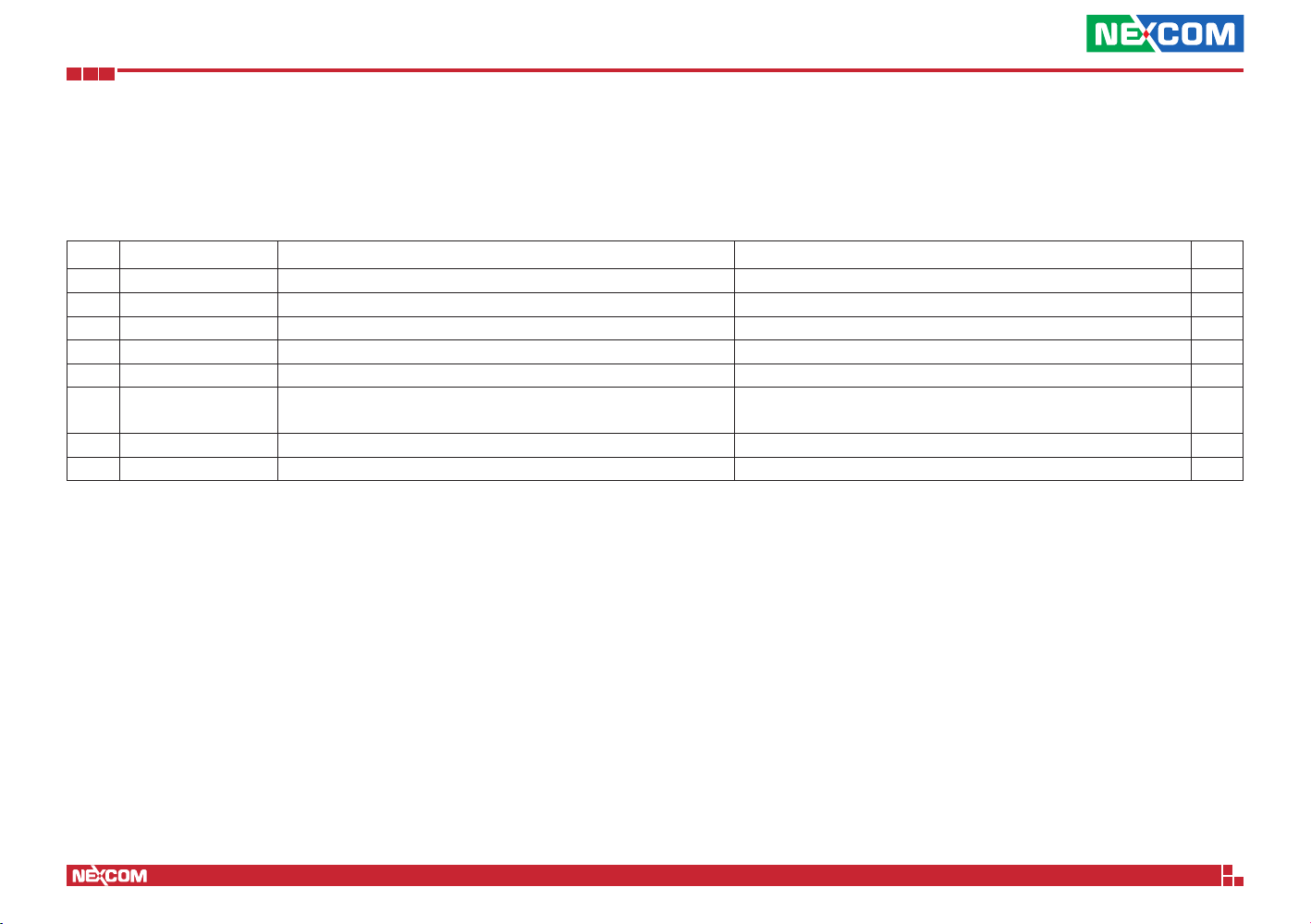
Before continuing, verify that the NSA 5170C package that you received is
complete. Your package should have all the items listed in the following table.
Item Part Number Name Description Qty
1 19S00517002X0 NSA 5170C ASSY 1
2 5044440031X00 Rubber Foot Kang Yang:RF20-5-4P 19.8x18x5.0mm 4
3 6012200052X00 PE Zipper Bag #8 170x240mm, w/China RoHS Symbol 1
4 6012200053X00 PE Zipper Bag #3 100x70mm, w/China RoHS Symbol 1
5 6023309081X00 Cable EDI:232091081804-RS COM Port. DB9 Female to RJ45 8P8C L:1800mm 1
6 5040210027X00 Ear Set for NSA 5180 VER:A PANADVANCE
7 5040150001X00 NSA 7135 AL Handle VER:A PANADVANCE 78x58x8mm 1
8 6014605586X00 Outside Carton Label for NSA 5170C VER:A Label Jet 60x60mm ART Paper 1
78x43x22mm SECC T=2.0mm
Painting Color:Pantone 295U Powder and Liquid
1
Copyright © 2018 NEXCOM International Co., Ltd. All Rights Reserved.
xiii
NSA 5170C User Manual
Page 14
Preface
Ordering Information
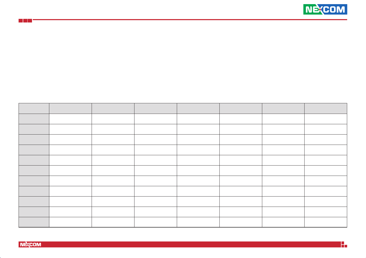
The following below provides ordering information for NSA 5170C.
Barebone
NSA 5170C (P/N: 10S00517002X0)
Supports Intel® 6th Gen. Xeon®/Core™/Pentium® processors, 4 x DDR4
memory slots, 2 x PCIe GbE LAN ports, CF card socket, USB ports, VGA port,
2 x PCIe x8 LAN and 2 x PCIe x4 LAN expansion slots (front), w/o LCM
Model P/N Controller Interface Type Port Number Bypass/Segment Expansion Slot Location Slot
NX 140F 10S20140F01X0 XL710-BM1 PCIe x8 4 SFP+ None None 1,2
NX 142F 10S20142F01X0 XL710-BM1 PCIe x8 4 SFP+ 2 bypass None 1,2
NX 120F 10S20120F00X0 X710-BM2 PCIe x8 2 SFP+ None One 1,2
NI 140F 10SK000NI02X0 i350AM4x1 PCIe x8 4 SFP None None All Slot
NI 180F 10S10180F01X0 i350AM4x2 PCIe x8 8 SFP None One 2
NI 142C 10SK000NI03X0 i350AM4x1 PCIe x8 4 Copper 2 bypass None All Slot
NI 180C 10S10180C01X0 i350AM4x2 PCIe x8 8 Copper None None 2
NI 184C 10S10184C01X0 i350AM4x2 PCIe x8 8 Copper 4 bypass None 2
NI 142F 10S10142F01X0 i350AM4x1 PCIe x8 4 SFP 2 bypass None All Slot
NI 121F 10S10121F01X0 i350AM2x1 PCIe x8 2 SFP 1 bypass None All Slot
NI 140C 10S10140C01X0 i350AM4x1 PCIe x8 4 Copper None None All Slot
Copyright © 2018 NEXCOM International Co., Ltd. All Rights Reserved.
xiv
NSA 5170C User Manual
Page 15
Chapter 1: Product Introduction
ChaPter 1: ProduCt IntroduCtIon
Overview
Key Features
▪ 1U up workstation rack mount system
®
6th Xeon®/CoreTM/Pentium® processor
▪ Intel
▪ Support DDR4 2400
Copyright © 2018 NEXCOM International Co., Ltd. All Rights Reserved.
▪ Four LAN module slots
▪ Support LCM module
1
NSA 5170C User Manual
Page 16

Chapter 1: Product Introduction
Hardware Specifications
Main Board
▪ NSB 5170C
▪ Intel® 6th Gen. Xeon®/CoreTM/Pentium® processors
▪ Intel® C236
Main Memory
▪ 4 x DDR4 2133 memory DIMM support ECC/non-ECC memory,
max. 64GB
LAN Features
▪ Swappable LAN modules
▪ Support Intel® i350/Intel® XL710 copper/fiber ports
▪ Support 10/100/1000/10G link speed
▪ LAN bypass
* Please see LAN module list information
I/O Interface-Front
▪ Power status/HDD status/2 x GPIO status LEDs
▪ 1 x Management port (LAN chip: Intel® i210)
▪ 2 x USB 2.0 ports
▪ 1 x RJ45 type console port
▪ 1 x Reset button
▪ 4 x PCIe Gen.3 LAN module slots (x8, x8, x4, x4)
I/O Interface-Rear
▪ 1 x VGA port
▪ 1 x Power button switch (optional)
▪ 1 x USB 2.0 port (optional)
Devices
▪ 1 x CF card
▪ 1 x 2.5” HDD bay
Power Input
▪ Power supply 220W (1+1) redundant PSU
Dimensions
▪ Chassis dimension: 438 mm x 480mm x 44mm
▪ Carton dimension: TBC
Weight
▪ Without packing: TBC
▪ With packing: TBC
Certifications
▪ CE approval
▪ FCC Class A
▪ UL
Copyright © 2018 NEXCOM International Co., Ltd. All Rights Reserved.
2
NSA 5170C User Manual
Page 17
Chapter 1: Product Introduction
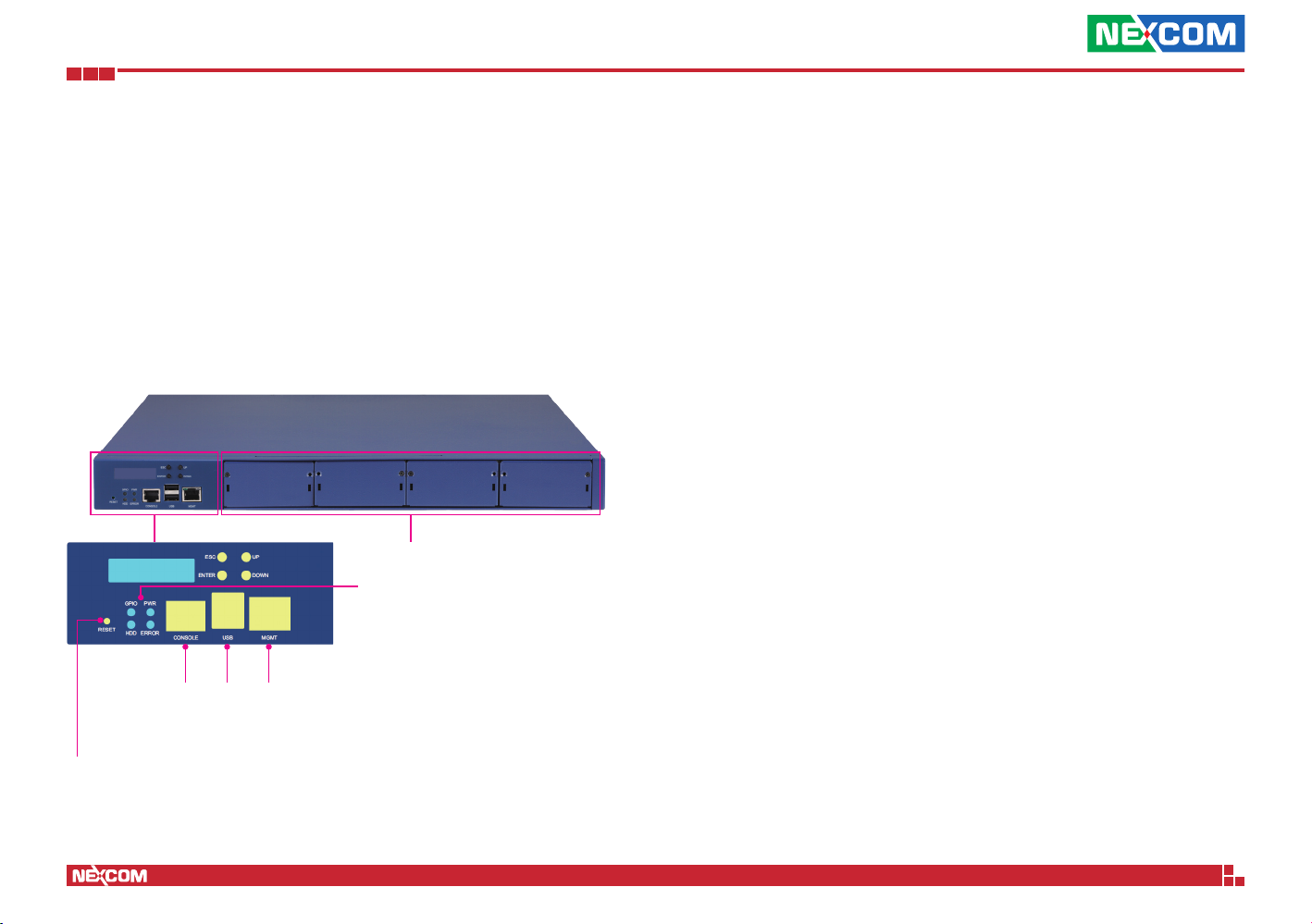
Knowing Your NSA 5170C
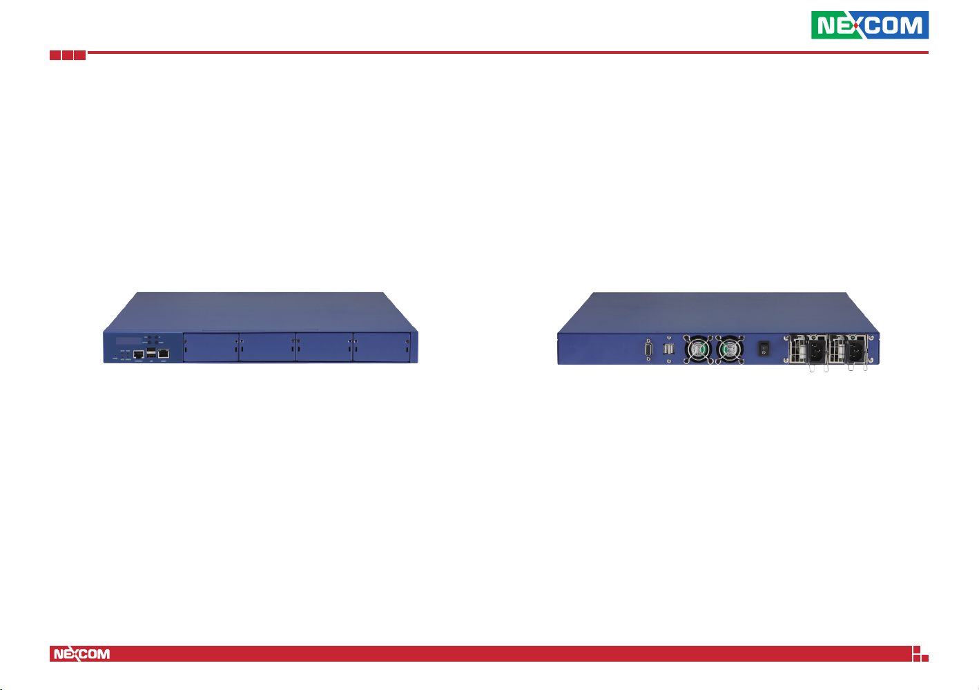
Front Panel
LAN Modules
LED Indicators
Reset Button
Press to restart the system.
LED Indicators
Indicates the power, storage drive and GPIO activity of the system.
RJ45 Type Console Serial Port
Used to connect RJ45 type console devices.
USB Ports
Used to connect USB 2.0 devices.
Management LAN Port
Management LAN port used for managing the system.
LAN Modules
Four LAN module bays to install add-on network modules.
Management
RJ45 Type
Console Port
Reset
Button
Copyright © 2018 NEXCOM International Co., Ltd. All Rights Reserved.
USB
Ports
LAN
3
NSA 5170C User Manual
Page 18
Chapter 1: Product Introduction
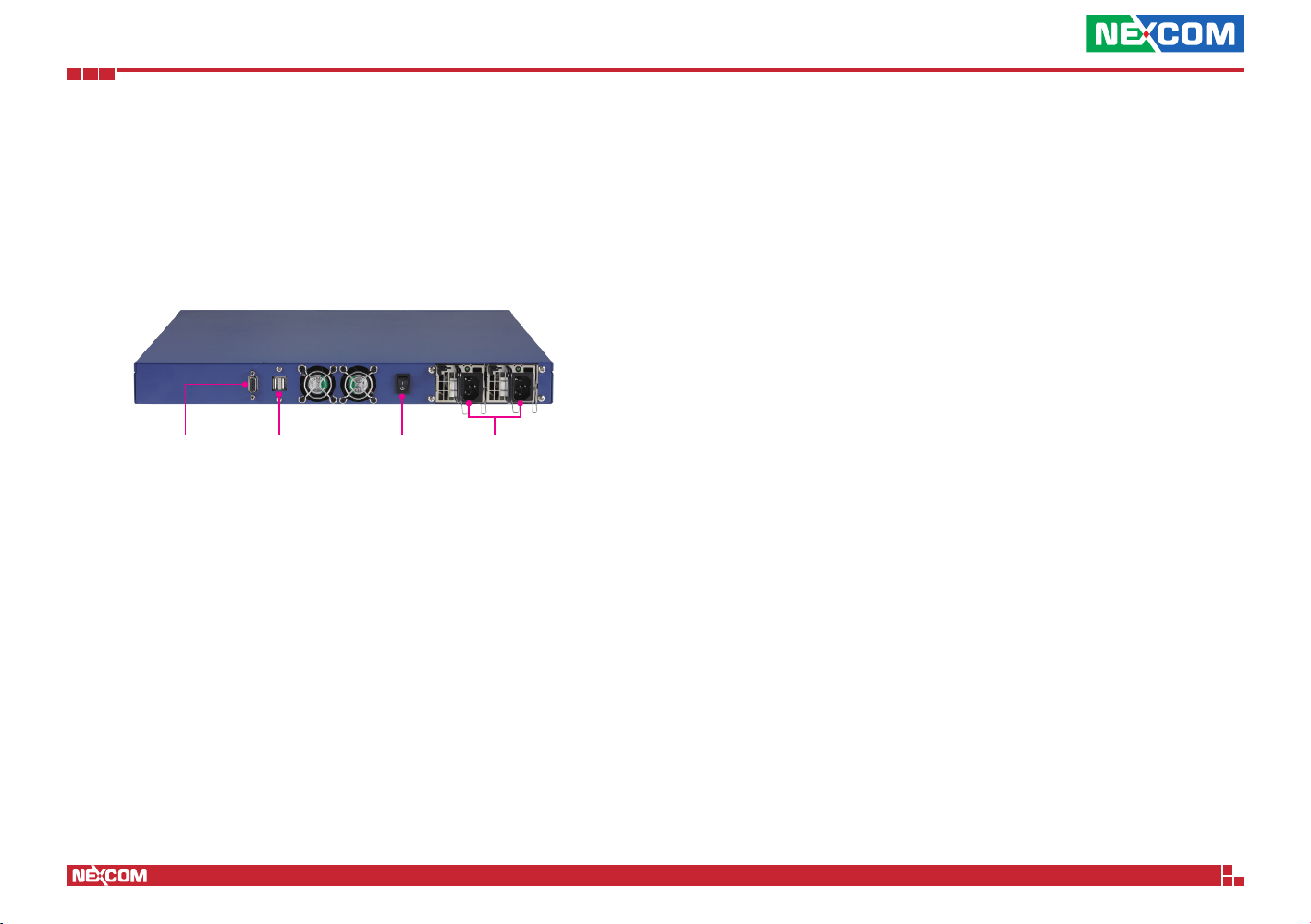
Rear Panel
VGA USB Port
(Optional)
Power Switch
(Optional)
VGA
Used to connect an analog VGA monitor.
USB Port (Optional)
Used to connect USB 2.0/1.1 devices.
Power Switch (Optional)
Press to power-on or power-off the system.
AC Power Sockets
Dual redundant power supply sockets, plug an AC power cord here before
turning on the system.
AC Power
Sockets
Copyright © 2018 NEXCOM International Co., Ltd. All Rights Reserved.
4
NSA 5170C User Manual
Page 19

Chapter 2: Jumpers and Connectors
ChaPter 2: JumPers and ConneCtors
This chapter describes how to set the jumpers and connectors on the
NSA 5170C motherboard.
Before You Begin
▪ Ensure you have a stable, clean working environment. Dust and dirt can
get into components and cause a malfunction. Use containers to keep
small components separated.
▪ Adequate lighting and proper tools can prevent you from accidentally
damaging the internal components. Most of the procedures that follow
require only a few simple tools, including the following:
– A Philips screwdriver
– A flat-tipped screwdriver
– A set of jewelers screwdrivers
– A grounding strap
– An anti-static pad
▪ Using your fingers can disconnect most of the connections. It is
recommended that you do not use needle-nosed pliers to disconnect
connections as these can damage the soft metal or plastic parts of the
connectors.
▪ Before working on internal components, make sure that the power is off.
Ground yourself before touching any internal components, by touching
a metal object. Static electricity can damage many of the electronic
components. Humid environments tend to have less static electricity than
dry environments. A grounding strap is warranted whenever danger of
static electricity exists.
Precautions
Computer components and electronic circuit boards can be damaged by
discharges of static electricity. Working on computers that are still connected
to a power supply can be extremely dangerous.
Follow the guidelines below to avoid damage to your computer or yourself:
▪ Always disconnect the unit from the power outlet whenever you are
working inside the case.
▪ If possible, wear a grounded wrist strap when you are working inside the
computer case. Alternatively, discharge any static electricity by touching
the bare metal chassis of the unit case, or the bare metal body of any
other grounded appliance.
▪ Hold electronic circuit boards by the edges only. Do not touch the
components on the board unless it is necessary to do so. Don’t flex or
stress the circuit board.
▪ Leave all components inside the static-proof packaging that they shipped
with until they are ready for installation.
▪ Use correct screws and do not over tighten screws.
Copyright © 2018 NEXCOM International Co., Ltd. All Rights Reserved.
5
NSA 5170C User Manual
Page 20
Chapter 2: Jumpers and Connectors
Jumper Settings
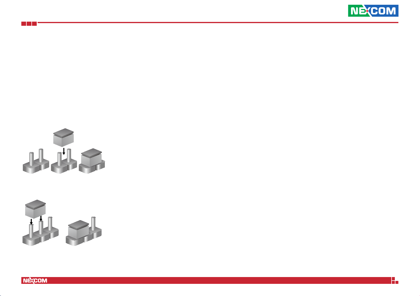
A jumper is the simplest kind of electric switch. It consists of two metal
pins and a cap. When setting the jumpers, ensure that the jumper caps are
placed on the correct pins. When the jumper cap is placed on both pins, the
jumper is short. If you remove the jumper cap, or place the jumper cap on
just one pin, the jumper is open.
Refer to the illustrations below for examples of what the 2-pin and 3-pin
jumpers look like when they are short (on) and open (off).
Two-Pin Jumpers: Open (Left) and Short (Right)
Three-Pin Jumpers: Pins 1 and 2 are Short
3
2
1
Copyright © 2018 NEXCOM International Co., Ltd. All Rights Reserved.
1
3
2
6
NSA 5170C User Manual
Page 21
Chapter 2: Jumpers and Connectors
CN1 CN2 CN5
CN3
14
3M
4M
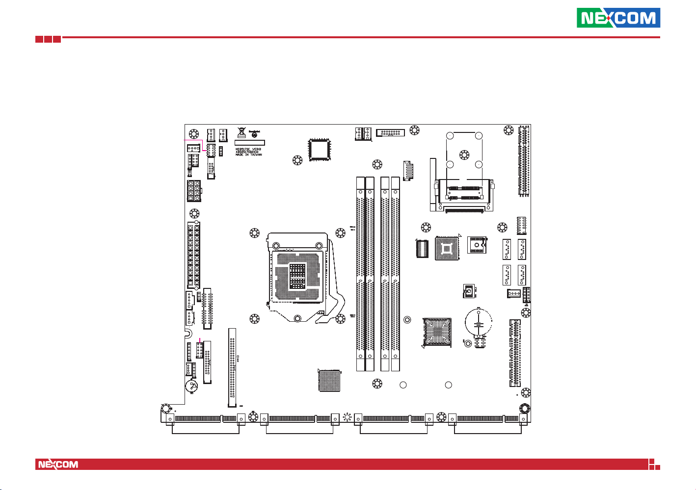
Locations of the Jumpers and Connectors
The figure below shows the location of the jumpers and connectors.
414
J2
H3
1
10
4
1
8
5
JP15
1
1
2
2
1
8
4
1
5
12
1
5
3
1
JP5
JP4
1
4
CN15
1
H16
CN16
10
6
JP7
1
2
5
4
1
1
JP10
B49
JP14
H7
24
13
9
1
JP17
2
26
2
20
2
10
2
1
25
1
19
1
13
1
CN8
CN14
B11
B12
JP2
H5
H13H10
50
49
CN19
2
1
JP11
B1
B49
B1
B11
B12
JP1
CN4
CN9
CON1
LCM1
CPU1
H11
H14
4
1
VGACONN1
H6
1
145
145
2
146
2
1
146
77
220772207722077220
143
288
143
287
144
144
287
288
H18
B49
2
16
1
15
6
J1
1
1
145
145
2
2
146
1
146
H15
143
288
143
287
144
144
287
288
H19
B11
B12
H1
H5
H4
MH
16
2
CN7
1
15
H8
H20
H27
B1
B49
H2
H6
MH
18
51
17
IDE1
JP3
13
14
H9
CN10CN12
17
7
1
1
CON2
B2B1A1
2
CN11
CN13
1
71
1
7
5
4
JP16
1
1
H12
A2
BAT1
H17
JP6
JP18
H21
B48
B49
A49
A48
H23
H24
B1
B11
B12
Copyright © 2018 NEXCOM International Co., Ltd. All Rights Reserved.
7
NSA 5170C User Manual
Page 22
Chapter 2: Jumpers and Connectors
15
26
Jumpers
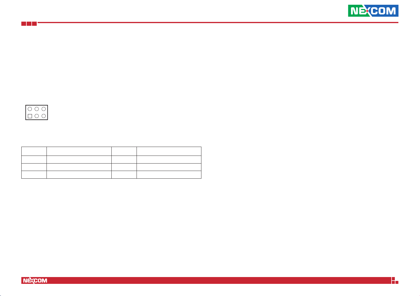
CMOS Clear Jumper
Connector type: 2x3 6-pin header, 2.54mm pitch
Connector location: JP6
Pin Definition Pin Definition
1 N/A 2 ROMA0
3 RST_RTCRST_N 4 ROMA_0_R
5 GND 6 80port_debug_sw
Copyright © 2018 NEXCOM International Co., Ltd. All Rights Reserved.
8
NSA 5170C User Manual
Page 23
Chapter 2: Jumpers and Connectors
19
21
Connector Pin Definitions
Internal Connectors
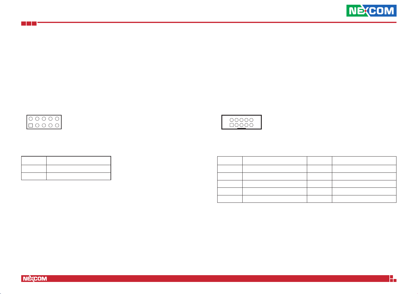
System Reset Header
Connector type: 2x5 10-pin header, 2.54mm pitch
Connector location: CN16
0
Pin Definition
9 GND
10 System Reset
COM1 Header
Connector type: 2x5 10-pin header
Connector location: CN8
2
1
Pin Definition Pin Definition
1 COM2_DCD 2 COM2_RXD
3 COM2_TXD 4 COM2_DTR
5 GND 6 COM2_DSR
7 COM2_RTS 8 COM2_CTS
9 COM2_RI 10 GND
10
9
Copyright © 2018 NEXCOM International Co., Ltd. All Rights Reserved.
9
NSA 5170C User Manual
Page 24
Chapter 2: Jumpers and Connectors
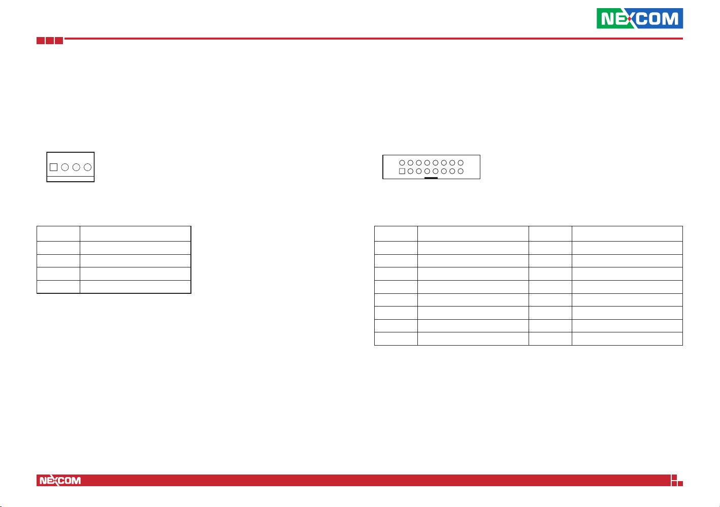
Fan Connectors
Connector type: 1x4 4-pin Wafer
Connector location: CN1, CN2, CN3, CN4 and CN5
1 4
Pin Definition
1 GND
2 P12V
3 TACH
4 PWM
VGA Connector
Connector type: 2x8 16-pin header
Connector location: VGACONN1
2
1
Pin Definition Pin Definition
1 DACROA_B 2 DACGOA_B
3 DACBOA_B 4 N/A
5 GND 6 GND
7 GND 8 GND
9 VGA_VCC 10 GND
11 N/A 12 DDC_DATAO_B
13 AHSYNCO_B 14 AVSYNCO_B
15 DDC_CLKO_B 16 N/A
16
15
Copyright © 2018 NEXCOM International Co., Ltd. All Rights Reserved.
10
NSA 5170C User Manual
Page 25
Chapter 2: Jumpers and Connectors
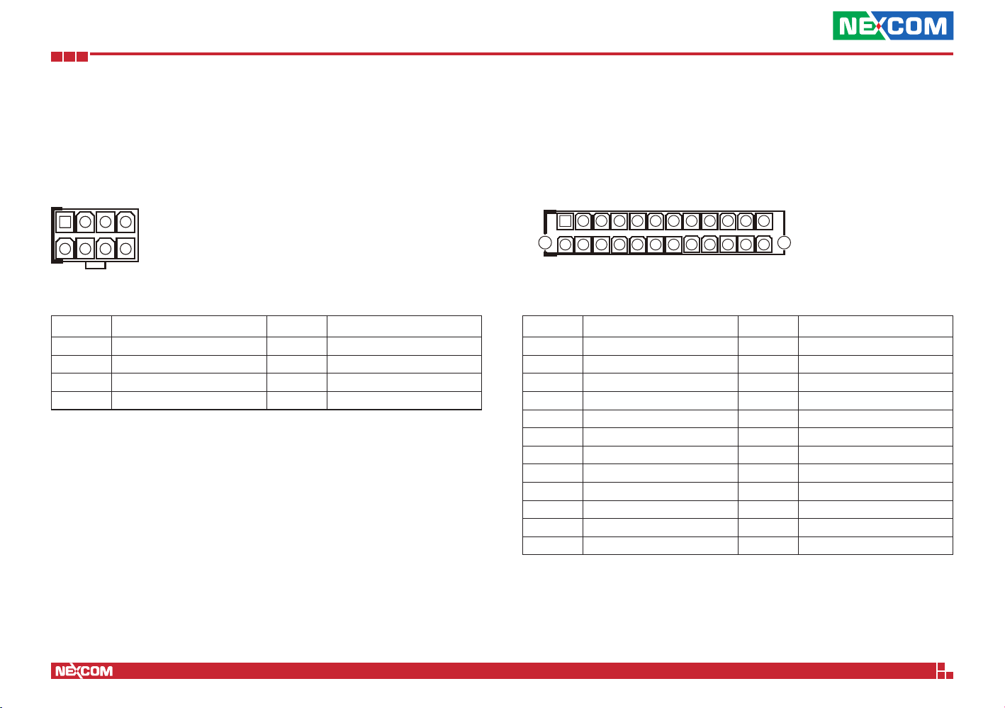
8-pin Internal Power Connector
Connector type: 2x4 8-pin boxed header, 4.2mm pitch
Connector location: CN9
1 4
5 8
Pin Definition Pin Definition
1 GND 2 GND
3 GND 4 GND
5 P12V 6 P12V
7 P12V 8 P12V
24-pin Internal Power Connector
Connector type: 2x12 24-pin boxed header, 4.2mm pitch
Connector location: CON1
1 12
2413
Pin Definition Pin Definition
1 +3.3V 2 +3.3V
3 GND 4 +5V
5 GND 6 +5V
7 GND 8 PW-OK
9 +5VSB 10 +12V
11 +12V 12 +3.3V
13 +3.3V 14 -12V
15 GND 16 PS-ON
17 GND 18 GND
19 GND 20 RES/-5V
21 +5V 22 +5V
23 +5V 24 GND
Copyright © 2018 NEXCOM International Co., Ltd. All Rights Reserved.
11
NSA 5170C User Manual
Page 26
Chapter 2: Jumpers and Connectors
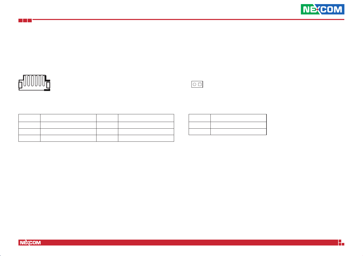
Rear USB 2.0 Connector
Connector type: 1x6 6-pin header, 2.0mm pitch
Connector location: J1
6 1
Pin Definition Pin Definition
1 P5V_USB_P01 2 USB2N0_C
3 USB2P0_C 4 USB2N1_C
5 USB2P1_C 6 GND
Power Button
Connector type: 1x2 2-pin header, 2.54mm pitch
Connector location: J2
12
Pin Definition
1 GND
2 FP_PWR_BTN_N
Copyright © 2018 NEXCOM International Co., Ltd. All Rights Reserved.
12
NSA 5170C User Manual
Page 27
Chapter 2: Jumpers and Connectors
19
21
11
21
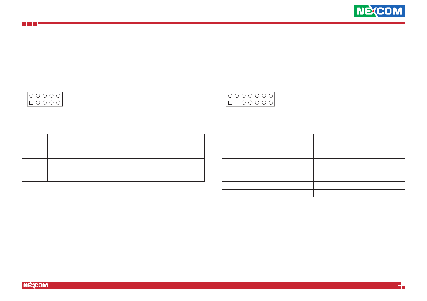
GPIO Pin Header
Connector type: 2x5 10-pin header
Connector location: JP1
0
Pin Definition Pin Definition
1 P3V3 2 GND
3 SW_GPIN1 4 SW_GPOUT1
5 SW_GPIN2 6 SW_GPOUT2
7 SW_GPIN3 8 SW_GPOUT3
9 SW_GPIN4 10 SW_GPOUT4
TPM Header
Connector type: 2x7 14-pin header, 2.0mm pitch
Connector location: JP3
4
3
Pin Definition Pin Definition
1 GND 2 CLK_LPC_TPM_R
3 N/A 4 LPC_FRAME_R1_N
5 LPC_AD2_R1 6 RST_TPM_R1_N
7 LPC_AD1_R1 8 LPC_AD3_R1
9 GND 10 LPC_AD0_R1
11 INT_SERIRQ_R1 12 P3V3
13 GND 14 GND
Copyright © 2018 NEXCOM International Co., Ltd. All Rights Reserved.
13
NSA 5170C User Manual
Page 28
Chapter 2: Jumpers and Connectors
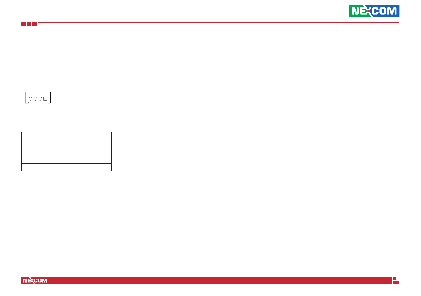
LCM
Connector type: 1x4 4-pin header, 2.0mm pitch
Connector location: LCM1
14
Pin Definition
1 GND
2 SP_LCM_RXD
3 SP_LCM_TXD
4 P3V3
Copyright © 2018 NEXCOM International Co., Ltd. All Rights Reserved.
14
NSA 5170C User Manual
Page 29
Chapter 2: Jumpers and Connectors
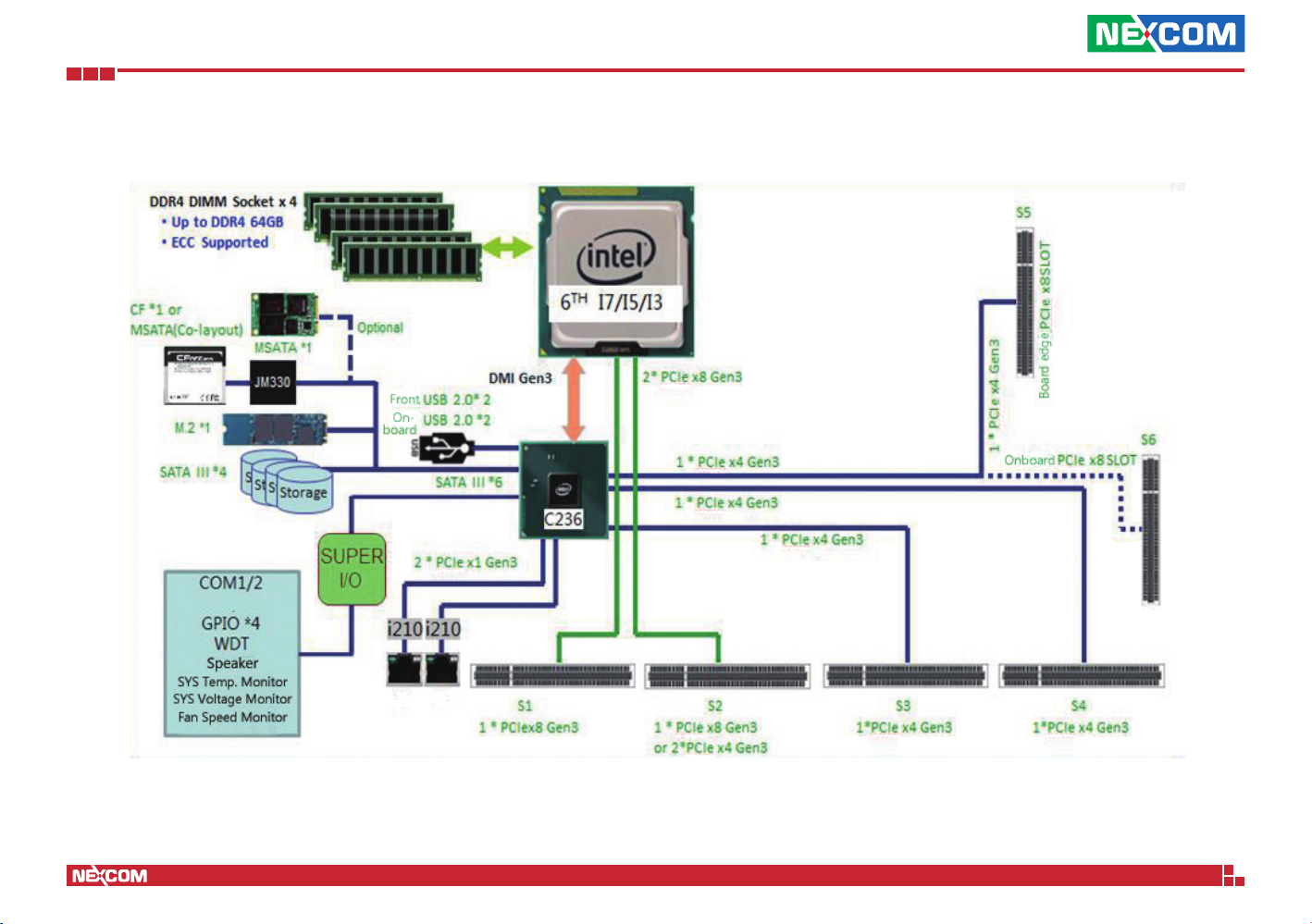
Block Diagram
Copyright © 2018 NEXCOM International Co., Ltd. All Rights Reserved.
15
NSA 5170C User Manual
Page 30
Chapter 3: System Setup
ChaPter 3: system setuP
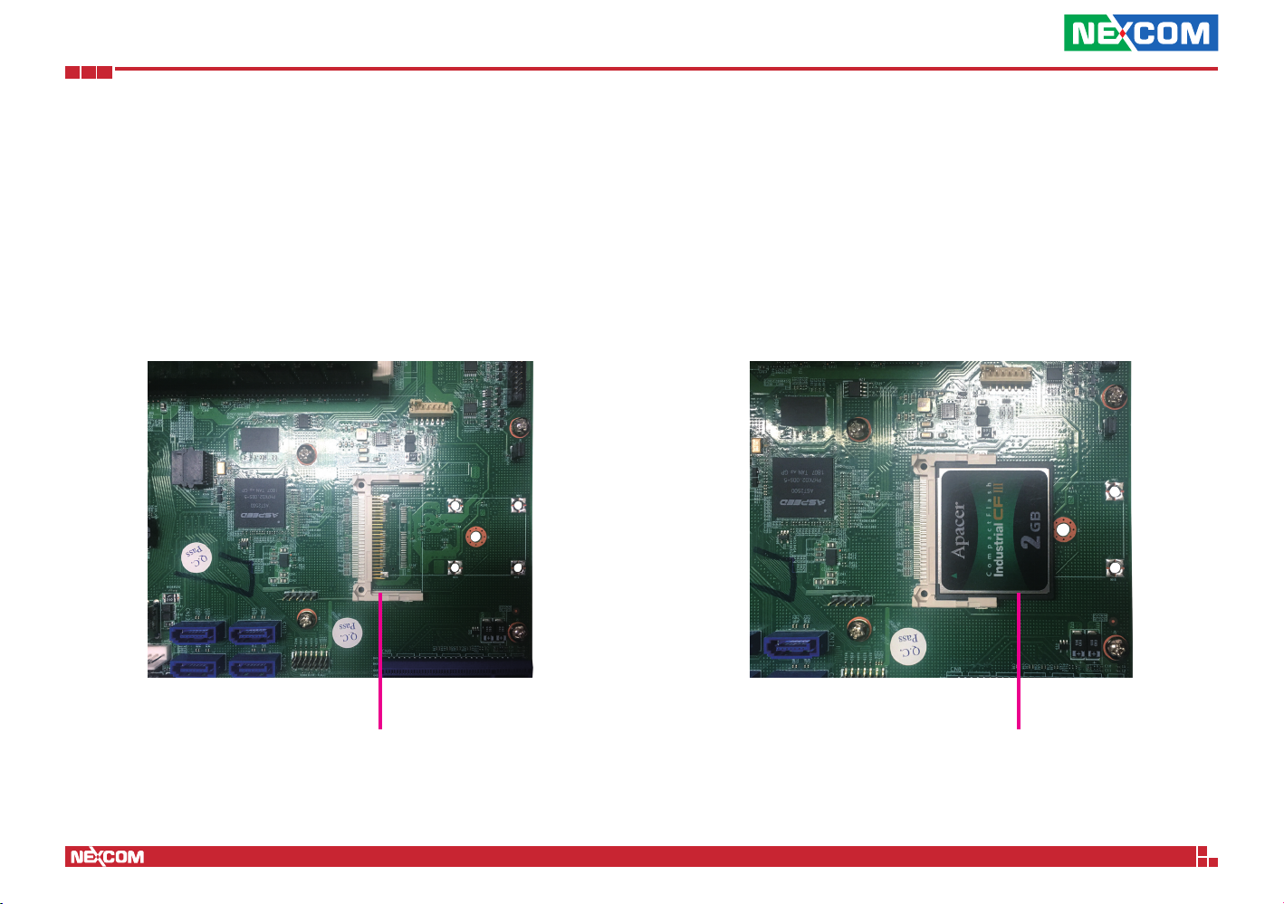
Installing a CompactFlash (CF) Card
1. With the chassis cover removed, locate the CF slot on the motherboard.
CF Slot CF Module
2. Insert the CF module until it is completely seated into the slot.
Copyright © 2018 NEXCOM International Co., Ltd. All Rights Reserved.
16
NSA 5170C User Manual
Page 31
Chapter 3: System Setup
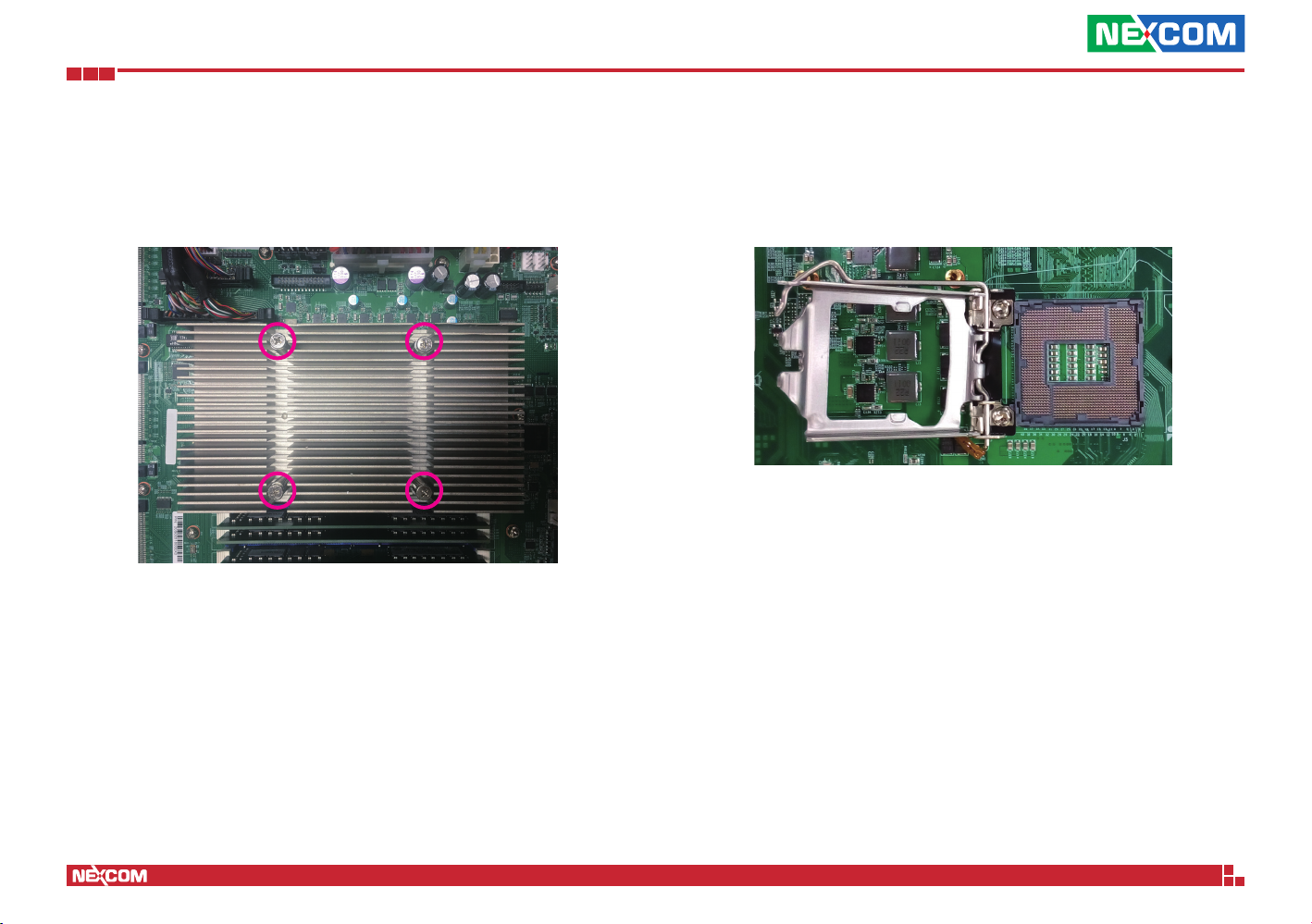
Installing a CPU
1. Loosen the four screws on the heat sink to remove it and access the CPU
socket.
2. Unlock the socket by pushing the load lever down, moving it sideways
until it is released from the retention tab; then lift the load lever up.
Copyright © 2018 NEXCOM International Co., Ltd. All Rights Reserved.
17
NSA 5170C User Manual
Page 32
Chapter 3: System Setup
CAUTION!
CAUTION!
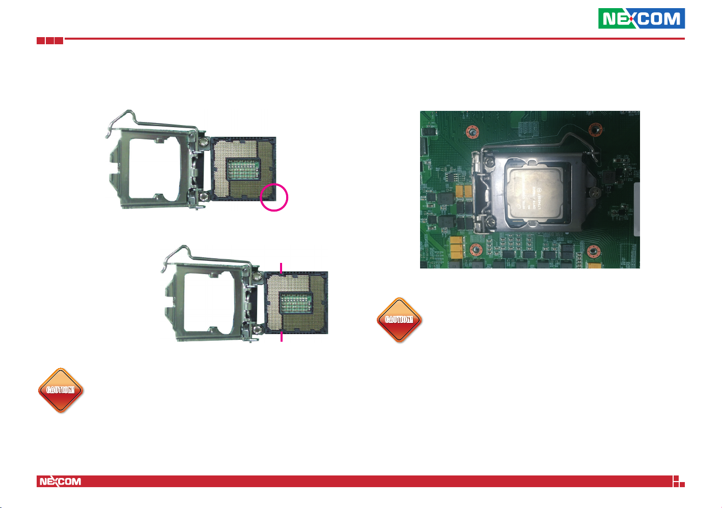
3. Insert the CPU into the socket. The triangular edge on the CPU must
align with the corner of the CPU socket shown on the photo.
Alignment Key
The CPU’s notch will at
the same time fit into the
socket’s alignment key.
Alignment Key
4. Close the load plate and then hook the load lever under the retention
tab.
CAUTION!CAUTION!
Do not force the CPU into the socket. Forcing the CPU into
the socket may bend the pins and damage the CPU.
▪ Handle the CPU by its edges and avoid touching the pins.
CAUTION!CAUTION!
▪ The CPU will fit in only one orientation and can easily be
inserted without exerting any force.
Copyright © 2018 NEXCOM International Co., Ltd. All Rights Reserved.
18
NSA 5170C User Manual
Page 33
Chapter 3: System Setup
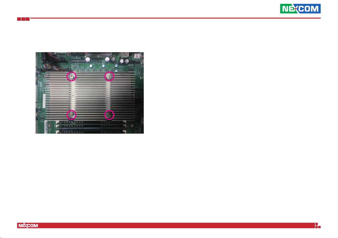
5. Place the heat sink back to its original location and apply all the four
screws to secure it in place.
Copyright © 2018 NEXCOM International Co., Ltd. All Rights Reserved.
19
NSA 5170C User Manual
Page 34
Chapter 3: System Setup
Installing DIMM Memory Modules
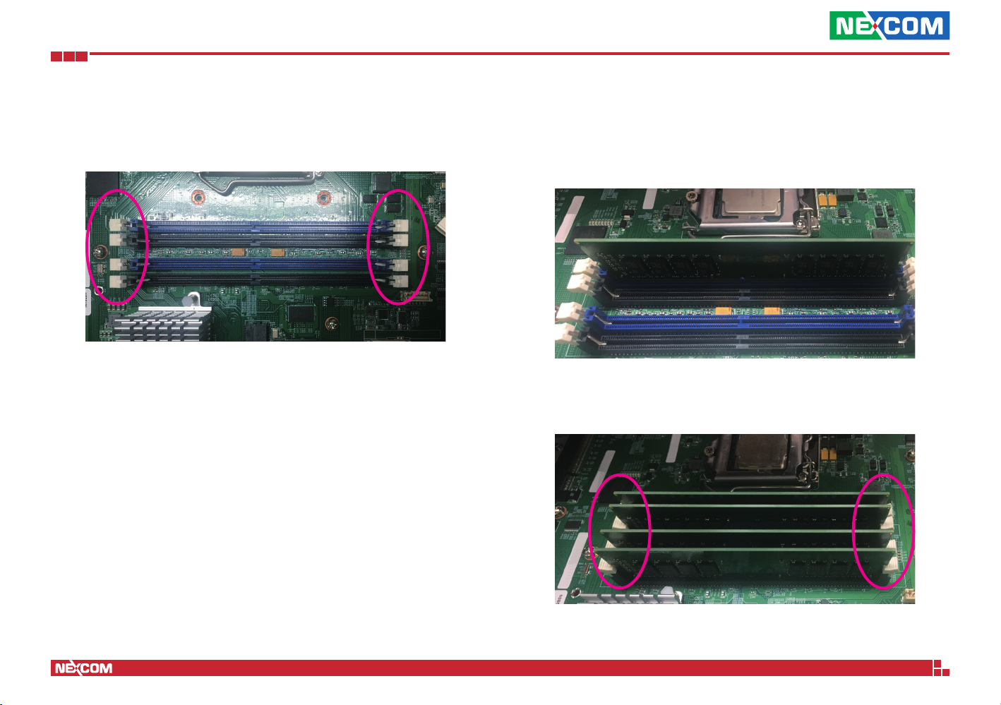
1. Locate the DIMM sockets on the board and release the locks.
2. Insert the module into the socket at an 90 degree angle. Apply firm even
pressure to each end of the module until it slips into the socket.
3. While pushing the modules into position, the lock will close automatically.
Copyright © 2018 NEXCOM International Co., Ltd. All Rights Reserved.
20
NSA 5170C User Manual
Page 35
Chapter 3: System Setup
CAUTION!
Installing a 2.5” SATA Hard Drive
CAUTION!CAUTION!
Please correctly follow the below instructions and
noted items to avoid making unnecessary damages.
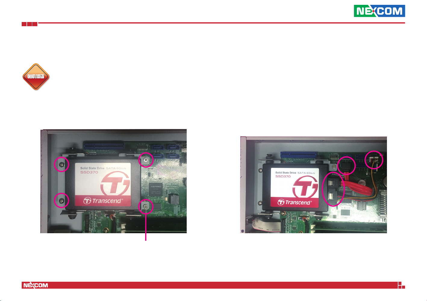
1. Install the SATA storage drive onto the storage drive bracket and secure
it to the chassis with mounting screws.
Mounting Screw
2. Connect the SATA data and power cables to the respective connectors
on the board and the other ends of the cables to the connectors on the
storage drive.
Copyright © 2018 NEXCOM International Co., Ltd. All Rights Reserved.
21
NSA 5170C User Manual
Page 36
Chapter 3: System Setup
CAUTION!
Installing a LAN Module
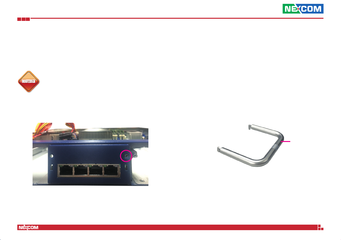
The system is equipped with 4 LAN module bays. To install a LAN module,
please follow the instructions below.
Please correctly follow the below instructions and noted
items to avoid making unnecessary damages. Make sure
CAUTION!CAUTION!
the power supply is switched off and disconnected from the
power sources before replacing or adding LAN modules to
prevent electric shock or system damage.
1. Remove the screw on the LAN module then put it in a safe place for
later use.
Copyright © 2018 NEXCOM International Co., Ltd. All Rights Reserved.
2. Use the handle provided, and insert the handle into the two holes on
the LAN module.
Handle
22
NSA 5170C User Manual
Page 37
Chapter 3: System Setup
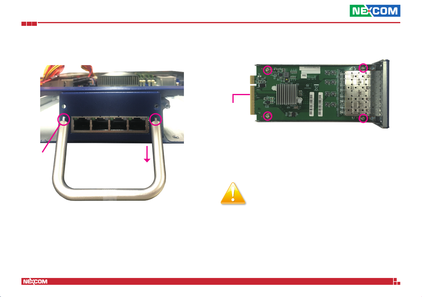
3. Once the handle is firmly secured in position, pull the handle outwards
to remove the LAN module tray.
Insert here
4. Place the LAN module into the tray making sure the connector side of
the module is at the rear side of the tray.
Connector
side
5. Secure the module in place with screws, and slide the tray back into the
bay.
Important:
Before using Optical fiber for transferring data, make sure
you have connected an approved Optical Transceiver Module.
User needs to install appropriate and UL approved Laser Class I
Transceivers, rated 3.3Vdc, max. 1W.
Copyright © 2018 NEXCOM International Co., Ltd. All Rights Reserved.
23
NSA 5170C User Manual
Page 38
Chapter 3: System Setup
Connecting the Power Switch (Optional)
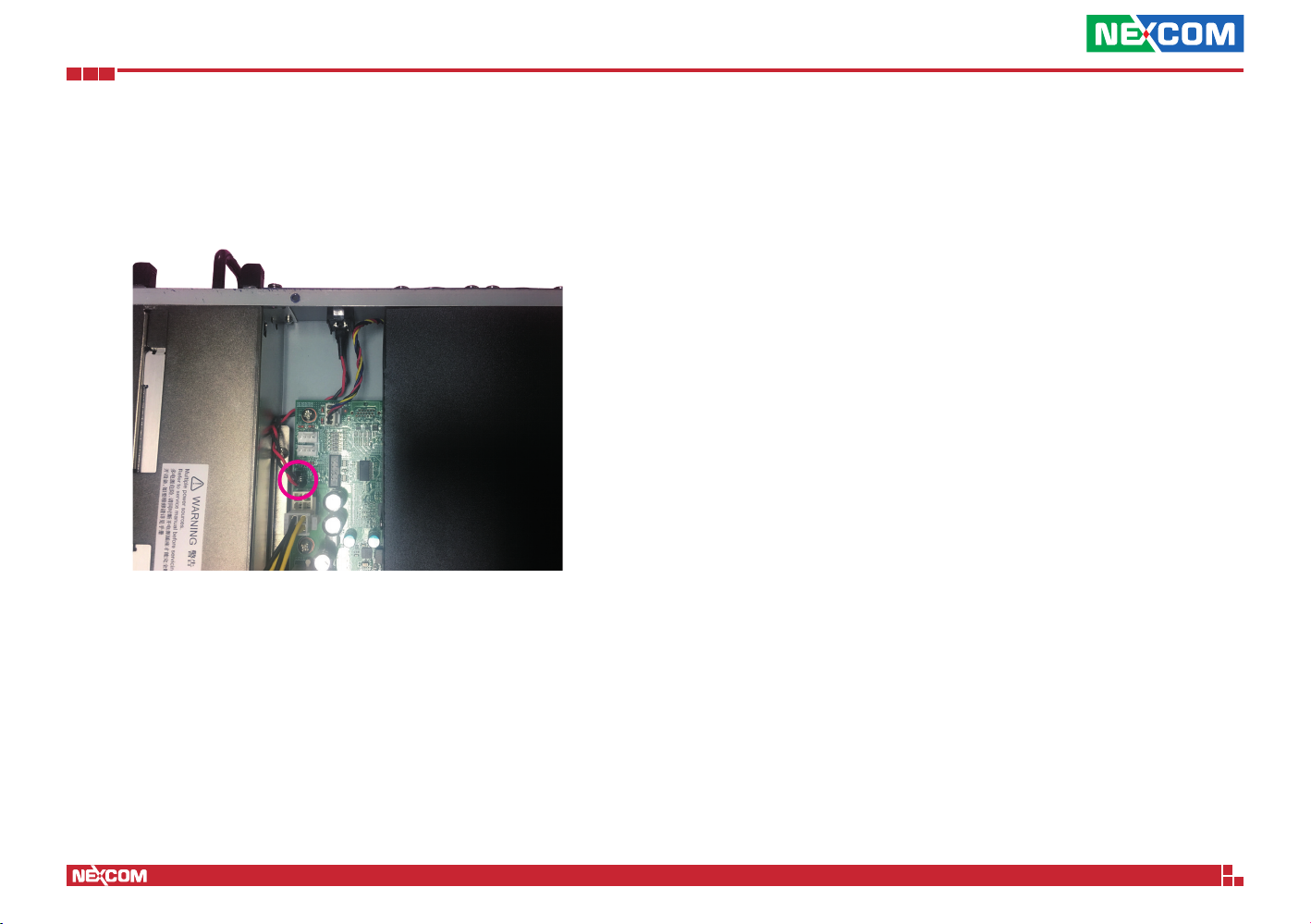
1. Connect the power switch cable to the power switch connector (J2) on
the board.
Copyright © 2018 NEXCOM International Co., Ltd. All Rights Reserved.
24
NSA 5170C User Manual
Page 39

Chapter 4: BIOS Setup
ChaPter 4: BIos setuP
This chapter describes how to use the BIOS setup program for the
NSA 5170C. The BIOS screens provided in this chapter are for reference only
and may change if the BIOS is updated in the future.
To check for the latest updates and revisions, visit the NEXCOM website at
www.nexcom.com.tw.
About BIOS Setup
The BIOS (Basic Input and Output System) Setup program is a menu driven
utility that enables you to make changes to the system configuration and
tailor your system to suit your individual work needs. It is a ROM-based
configuration utility that displays the system’s configuration status and
provides you with a tool to set system parameters.
These parameters are stored in non-volatile battery-backed-up CMOS RAM that
saves this information even when the power is turned off. When the system is
turned back on, the system is configured with the values found in CMOS.
With easy-to-use pull down menus, you can configure such items as:
▪ Hard drives, diskette drives, and peripherals
▪ Video display type and display options
▪ Password protection from unauthorized use
▪ Power management features
The settings made in the setup program affect how the computer performs.
It is important, therefore, first to try to understand all the setup options, and
second, to make settings appropriate for the way you use the computer.
When to Configure the BIOS
▪ This program should be executed under the following conditions:
▪ When changing the system configuration
▪ When a configuration error is detected by the system and you are
prompted to make changes to the setup program
▪ When resetting the system clock
▪ When redefining the communication ports to prevent any conflicts
▪ When making changes to the Power Management configuration
▪ When changing the password or making other changes to the security
setup
Normally, CMOS setup is needed when the system hardware is not consistent
with the information contained in the CMOS RAM, whenever the CMOS
RAM has lost power, or the system features need to be changed.
Copyright © 2018 NEXCOM International Co., Ltd. All Rights Reserved.
25
NSA 5170C User Manual
Page 40
Chapter 4: BIOS Setup
Default Configuration
Most of the configuration settings are either predefined according to
the Load Optimal Defaults settings which are stored in the BIOS or are
automatically detected and configured without requiring any actions. There
are a few settings that you may need to change depending on your system
configuration.
Entering Setup
When the system is powered on, the BIOS will enter the Power-On Self
Test (POST) routines. These routines perform various diagnostic checks; if an
error is encountered, the error will be reported in one of two different ways:
▪ If the error occurs before the display device is initialized, a series of beeps
will be transmitted.
▪ If the error occurs after the display device is initialized, the screen will
display the error message.
Powering on the computer and immediately pressing allows you to
enter Setup.
Legends
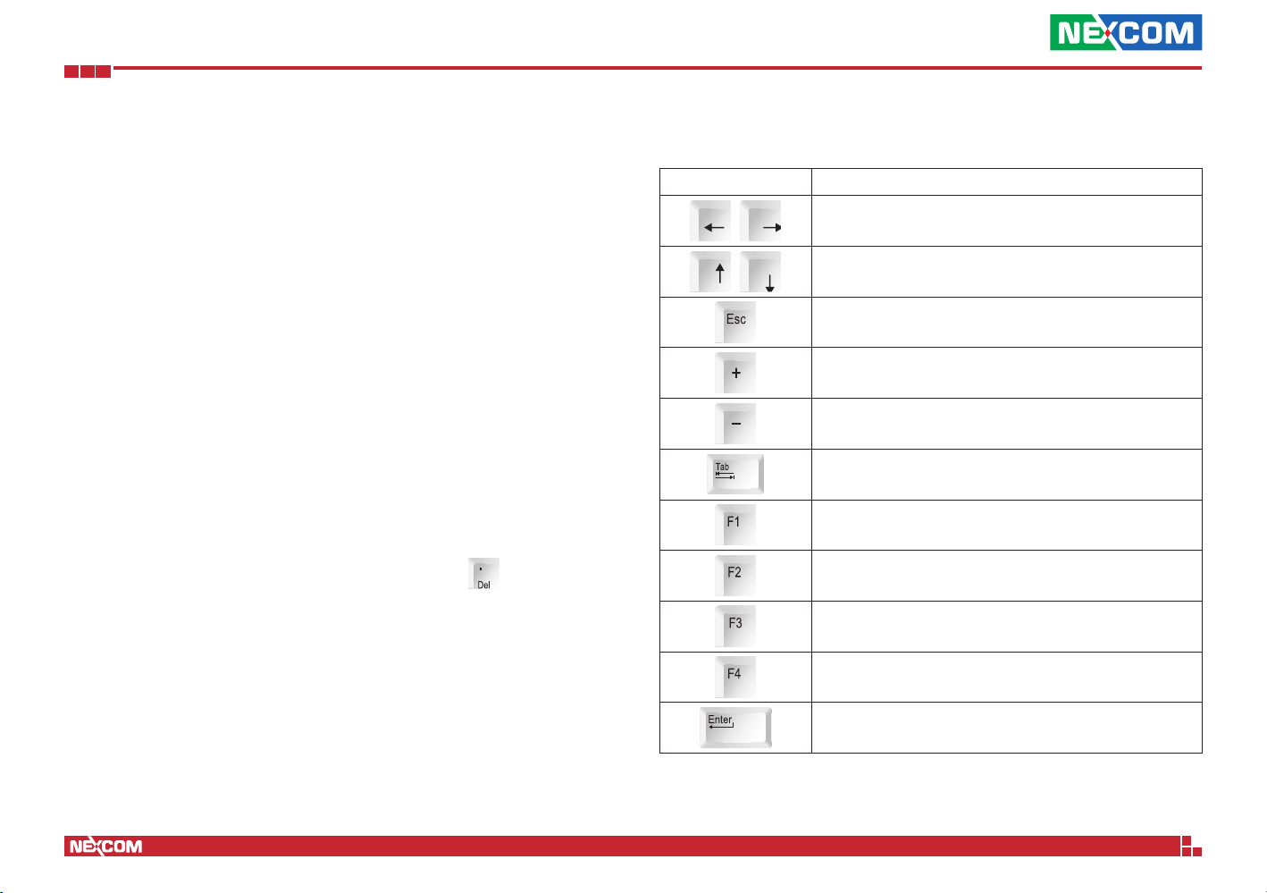
Key Function
Moves the highlight left or right to select a menu.
Moves the highlight up or down between sub-menu
or fields.
Exits the BIOS Setup Utility.
Scrolls forward through the values or options of the
highlighted field.
Scrolls backward through the values or options of
the highlighted field.
Selects a field.
Displays General Help.
Load previous values.
Load optimized default values.
Copyright © 2018 NEXCOM International Co., Ltd. All Rights Reserved.
26
Saves and exits the Setup program.
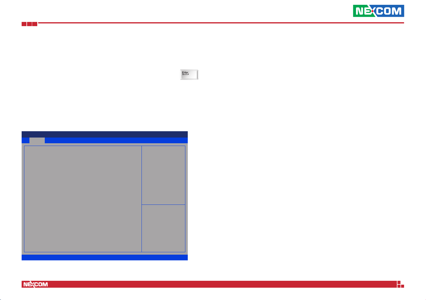
Press <Enter> to enter the highlighted sub-menu
NSA 5170C User Manual
Page 41

Chapter 4: BIOS Setup
Scroll Bar
When a scroll bar appears to the right of the setup screen, it indicates that
there are more available fields not shown on the screen. Use the up and
down arrow keys to scroll through all the available fields.
Submenu
When “” appears on the left of a particular field, it indicates that a
submenu which contains additional options are available for that field. To
display the submenu, move the highlight to that field and press .
Copyright © 2018 NEXCOM International Co., Ltd. All Rights Reserved.
27
NSA 5170C User Manual
Page 42
Chapter 4: BIOS Setup
BIOS Setup Utility
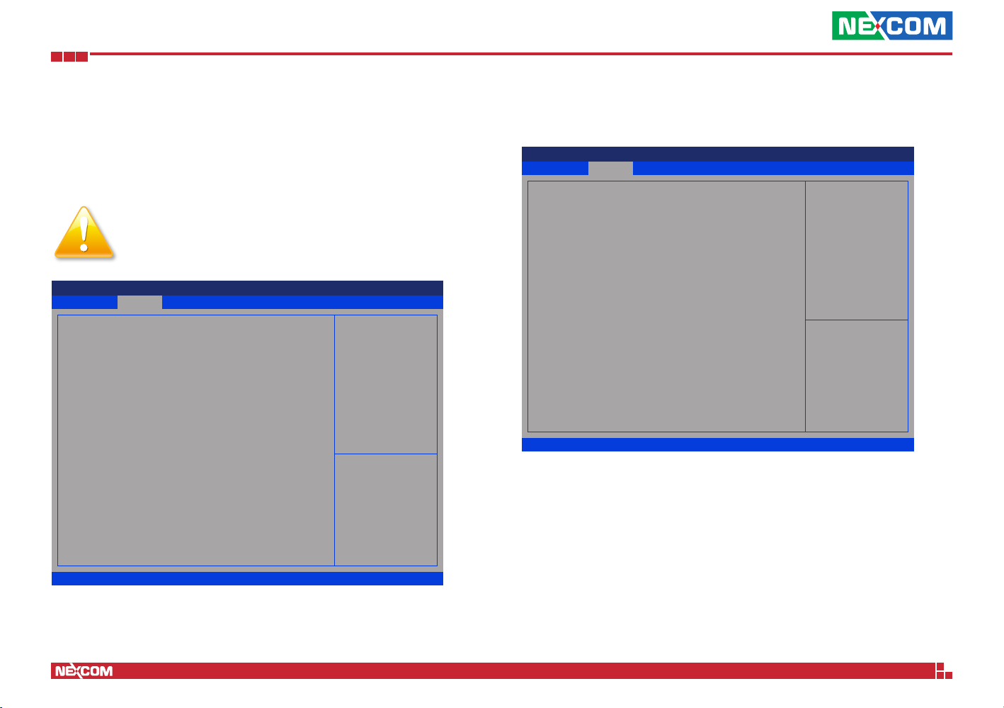
Once you enter the AMI BIOS Setup Utility, the Main Menu will appear on
the screen. The main menu allows you to select from several setup functions
and one exit. Use arrow keys to select among the items and press to
accept or enter the submenu.
Main
The Main menu is the first screen that you will see when you enter the BIOS
Setup Utility.
Aptio Setup Utility - Copyright (C) 2018 American Megatrends, Inc.
Save & ExitAdvanced Chipset Security BootMain
BIOS Information
BIOS Vendor
Core Version
Compliancy
Project Version
Build Date and Time
Access Level
Microcode Revision
System Date
System Time
American Megatrends
5.12
UEFI 2.6; PI 1.4
G767- 0.17 x64
08/01/2018 13:20:35
Administrator
8E
[Thu 08/29/2165]
[17:35:01]
Set the Date. Use Tab to switch
between Date elements.
→←: Select Screen
↑↓: Select Item
Enter: Select
+/-: Change Opt.
F1: General Help
F2: Previous Values
F3: Optimized Defaults
F4: Save & Exit
ESC: Exit
Access Level
Displays the access level of the current user in the BIOS.
System Date
The date format is <day>, <month>, <date>, <year>. Day displays a day,
from Monday to Sunday. Month displays the month, from January to
December. Date displays the date, from 1 to 31. Year displays the year, from
1999 to 2099.
System Time
The time format is <hour>, <minute>, <second>. The time is based on the
24-hour military-time clock. For example, 1 p.m. is 13:00:00. Hour displays
hours from 00 to 23. Minute displays minutes from 00 to 59. Second displays
seconds from 00 to 59.
Version 2.18.1263. Copyright (C) 2018 American Megatrends, Inc.
Copyright © 2018 NEXCOM International Co., Ltd. All Rights Reserved.
28
NSA 5170C User Manual
Page 43
Chapter 4: BIOS Setup
Advanced
The Advanced menu allows you to configure your system for basic operation.
Some entries are defaults required by the system board, while others, if
enabled, will improve the performance of your system or let you set some
features according to your preference.
Setting incorrect field values may cause the system to
malfunction.
Aptio Setup Utility - Copyright (C) 2018 American Megatrends, Inc.
Save & ExitAdvanced Chipset Security BootMain
CPU Conguration
Power & Performance
PCH-FW Conguration
Trusted Computing
IT8786 Super IO Conguration
Hardware Monitor
Serial Port Console Redirection
PCI Subsystem Settings
Network Stack Conguration
CSM Conguration
USB Conguration
CPU Conguration Parameters
→←: Select Screen
↑↓: Select Item
Enter: Select
+/-: Change Opt.
F1: General Help
F2: Previous Values
F3: Optimized Defaults
F4: Save & Exit
ESC: Exit
CPU Configuration
This section is used to configure the CPU.
Aptio Setup Utility - Copyright (C) 2018 American Megatrends, Inc.
Advanced
CPU Conguration
Type
ID
Speed
L1 Data Cache
L1 Instruction Cache
L2 Cache
L3 Cache
L4 Cache
VMX
SMX/TXT
Hardware Prefetcher
Intel (VMX)
Virtualization Technology
Version 2.18.1263. Copyright (C) 2018 American Megatrends, Inc.
Intel(R) Core(TM)
i7-7101TE CPU @ 3.40GHz
0x906E9
3400 MHz
32 KB x 2
32 KB x 2
256 KB x 2
3 MB
N/A
Supported
Not Supported
[Enabled]
[Enabled]
To turn on/off the MLC
streamer prefetcher.
→←: Select Screen
↑↓: Select Item
Enter: Select
+/-: Change Opt.
F1: General Help
F2: Previous Values
F3: Optimized Defaults
F4: Save & Exit
ESC: Exit
Hardware Prefetcher
Turns on or off the MLC streamer prefetcher.
Intel® Virtualization Technology
When this field is set to Enabled, the VMM can utilize the additional
hardware capabilities provided by Vanderpool Technology.
Version 2.18.1263. Copyright (C) 2018 American Megatrends, Inc.
Copyright © 2018 NEXCOM International Co., Ltd. All Rights Reserved.
29
NSA 5170C User Manual
Page 44
Chapter 4: BIOS Setup
Power & Performance
This section is used to configure the CPU power management features.
Aptio Setup Utility - Copyright (C) 2018 American Megatrends, Inc.
Advanced
CPU - Power Management Control
Intel(R)
SpeedStep(tm)
C states
Version 2.18.1263. Copyright (C) 2018 American Megatrends, Inc.
Intel® SpeedStep
TM
[Disabled]
[Disabled]
Allows more than two frequency
ranges to be supported.
→←: Select Screen
↑↓: Select Item
Enter: Select
+/-: Change Opt.
F1: General Help
F2: Previous Values
F3: Optimized Defaults
F4: Save & Exit
ESC: Exit
Enables or disables Intel SpeedStep.
C States
Enables or disables C-States support for power saving.
PCH-FW Configuration
This section is used to configure the firmware update options.
Aptio Setup Utility - Copyright (C) 2018 American Megatrends, Inc.
Advanced
ME Firmware Version
ME Firmware Mode
ME Firmware SKU
ME File System
Integrity Value
ME Firmware Status 1
ME Firmware Status 2
NFC Support
ME State
Version 2.18.1263. Copyright (C) 2018 American Megatrends, Inc.
11.8.55.3510
Normal Mode
Consumer SKU
2
0x90000255
0x6B000306
Disabled
[Enabled]
When Disabled ME will be put
into ME Temporarily Disabled
Mode.
→←: Select Screen
↑↓: Select Item
Enter: Select
+/-: Change Opt.
F1: General Help
F2: Previous Values
F3: Optimized Defaults
F4: Save & Exit
ESC: Exit
ME State
Enables or disables ME state. When disabled, ME will be placed into ME
Temporarily Disabled Mode.
Copyright © 2018 NEXCOM International Co., Ltd. All Rights Reserved.
30
NSA 5170C User Manual
Page 45
Chapter 4: BIOS Setup
Trusted Computing
This section is used to configure Trusted Platform Module (TPM) settings.
Aptio Setup Utility - Copyright (C) 2018 American Megatrends, Inc.
Advanced
TPM20 Device Found
Vendor: IFX
Firmware Version: 5.62
Security Device Support
Active PCR banks
Available PCR banks
SHA-1 PCR Bank
SHA256 PCR Bank
Pending operation
Platform Hierarchy
Storage Hierarchy
Endorsement
Hierarchy
TPM2.0 UEFI Spec
Version
Physical Presence
Spec Version
TPM 20
InterfaceType
Device Select
Version 2.18.1263. Copyright (C) 2018 American Megatrends, Inc.
[Enable]
SHA-1,SHA256
SHA-1,SHA256
[Enabled]
[Enabled]
[None]
[Enabled]
[Enabled]
[Enabled]
[TCG_2]
[1.3]
[TIS]
[Auto]
Enables or Disables BIOS
support for security device. O.S.
will not show Security Device.
TCG EFI protocol and INT1A
interface will not be available.
→←: Select Screen
↑↓: Select Item
Enter: Select
+/-: Change Opt.
F1: General Help
F2: Previous Values
F3: Optimized Defaults
F4: Save & Exit
ESC: Exit
Security Device Support
Enables or disables BIOS support for security device. O.S will not show
Security Device. TCG EFI protocol and INT1A interface will not be available.
Pending operation
Schedules an operation for the security device.
Platform Hierarchy
Enables or disables platform hierarchy.
Storage Hierarchy
Enables or disables storage hierarchy.
Endorsement Hierarchy
Enables or disables endorsement hierarchy.
TPM2.0 UEFI Spec Version
Configures the TPM2.0 UEFI spec version.
Physical Presence Spec Version
Configures the physical presence spec version.
Device Select
TPM 1.2 will restrict support to TPM 1.2 devices. TPM 2.0 will restrict support
to TPM 2.0 devices. Auto will support both TPM 1.2 and 2.0 devices with
the default set to TPM 2.0 devices if not found, and TPM 1.2 devices will be
enumerated.
SHA-1 PCR Bank
Enables or disables SHA-1 PCR Bank.
SHA256 PCR Bank
Enables or disables SHA256 PCR Bank.
Copyright © 2018 NEXCOM International Co., Ltd. All Rights Reserved.
31
NSA 5170C User Manual
Page 46
Chapter 4: BIOS Setup
IT8786 Super IO Configuration
This section is used to configure the serial ports.
Aptio Setup Utility - Copyright (C) 2018 American Megatrends, Inc.
Advanced
IT8786 Super IO Conguration
Super IO Chip
Serial Port 1 Conguration
Serial Port 4 Conguration
Version 2.18.1263. Copyright (C) 2018 American Megatrends, Inc.
IT8786
Super IO Chip
Displays the Super I/O chip used on the board.
Serial Port 1 Configuration
Configuration settings for serial port 1.
Set Parameters of Serial Port
1 (COMA)
→←: Select Screen
↑↓: Select Item
Enter: Select
+/-: Change Opt.
F1: General Help
F2: Previous Values
F3: Optimized Defaults
F4: Save & Exit
ESC: Exit
Serial Port 1 Configuration
This section is used to configure serial port 1.
Aptio Setup Utility - Copyright (C) 2018 American Megatrends, Inc.
Advanced
Serial Port 1 Conguration
Serial Port
Device Settings
Change Settings
Version 2.18.1263. Copyright (C) 2018 American Megatrends, Inc.
[Enabled]
IO=2E8h; IRQ=3;
[IO=2E8h;
IRQ=3,4,5,6,7,9,10,11,12;]
Serial Port
Enables or disables the serial port.
Change Settings
Selects an optimal setting for the Super IO device.
Enable or Disable Serial Port
(COM)
→←: Select Screen
↑↓: Select Item
Enter: Select
+/-: Change Opt.
F1: General Help
F2: Previous Values
F3: Optimized Defaults
F4: Save & Exit
ESC: Exit
Serial Port 4 Configuration
Configuration settings for serial port 4.
Copyright © 2018 NEXCOM International Co., Ltd. All Rights Reserved.
32
NSA 5170C User Manual
Page 47
Chapter 4: BIOS Setup
Serial Port 4 Configuration
This section is used to configure serial port 4.
Aptio Setup Utility - Copyright (C) 2018 American Megatrends, Inc.
Advanced
Serial Port 4 Conguration
Serial Port
Device Settings
Change Settings
Version 2.18.1263. Copyright (C) 2018 American Megatrends, Inc.
[Enabled]
IO=3F8h; IRQ=4;
[Auto]
Serial Port
Enables or disables the serial port.
Change Settings
Selects an optimal setting for the Super IO device.
Enable or Disable Serial Port
(COM)
→←: Select Screen
↑↓: Select Item
Enter: Select
+/-: Change Opt.
F1: General Help
F2: Previous Values
F3: Optimized Defaults
F4: Save & Exit
ESC: Exit
Hardware Monitor
This section is used to monitor hardware status such as temperature, fan
speed and voltages.
Aptio Setup Utility - Copyright (C) 2018 American Megatrends, Inc.
Advanced
Pc Health Status
CPU Temperature
System Temperature
CPU FAN Speed(CN3)
Fan2 Speed(CN1)
Fan3 Speed(CN2)
Fan4 Speed(CN4)
Fan5 Speed(CN5)
CPU:Vcore
3.3V
12V
5V
1.2V
Version 2.18.1263. Copyright (C) 2018 American Megatrends, Inc.
: +60 C
: +36 C
: 4192 RPM
: N/A
: 4192 RPM
: N/A
: N/A
: +1.020 V
: +3.346 V
: +0.72 V
: N/A
: +1.200 V
→←: Select Screen
↑↓: Select Item
Enter: Select
+/-: Change Opt.
F1: General Help
F2: Previous Values
F3: Optimized Defaults
F4: Save & Exit
ESC: Exit
CPU and System Temperature
Detects and displays the current CPU and system temperature.
CPU FAN Speed
Detects and displays the current CPU fan speed.
Copyright © 2018 NEXCOM International Co., Ltd. All Rights Reserved.
Fan2 to Fan5 Speed
Detects and displays the current fan2 to fan5 speed.
CPU:Vcore to 1.2V
Detects and displays the output voltages.
33
NSA 5170C User Manual
Page 48
Chapter 4: BIOS Setup
Serial Port Console Redirection
This section is used to configure the serial port that will be used for console
redirection.
Aptio Setup Utility - Copyright (C) 2018 American Megatrends, Inc.
Advanced
Console Redirection Enable or
COM0
Console Redirection
Console Redirection Settings
►
COM3
Console Redirection
Console Redirection Settings
►
Legacy Console Redirection
Legacy Console Redirection Settings
►
Serial Port for Out-of-Band Management /
Windows Emergency Management Services (EMS)
Console Redirection
Console Redirection Settings
►
Version 2.18.1263. Copyright (C) 2018 American Megatrends, Inc.
[Disabled]
[Enabled]
[Enabled]
Disable.
→←: Select Screen
↑↓: Select Item
Enter: Select
+/-: Change Opt.
F1: General Help
F2: Previous Values
F3: Optimized Defaults
F4: Save & Exit
ESC: Exit
Console Redirection
Enables or disables the console redirection.
Console Redirection Settings (COM3)
Specifies how the host computer and the remote computer (which the
user is using) will exchange data. Both computers should have the same or
compatible settings.
Aptio Setup Utility - Copyright (C) 2018 American Megatrends, Inc.
Advanced
COM3
Console Redirection Settings
Terminal Type
Bits per second
Data Bits
Parity
Stop Bits
Flow Control
VT-UTF8 Combo Key Support
Recorder Mode
Resolution 100x31
Putty KeyPad
Version 2.18.1263. Copyright (C) 2018 American Megatrends, Inc.
[VT100+]
[115200]
[8]
[None]
[1]
[None]
[Enabled]
[Disabled]
[Disabled]
[VT100]
Emulation: ANSI: Extended
ASCII char set. VT100: ASCII
char set. VT100+: Extends
VT100 to support color, function
keys, etc.
VT-UTF8: Uses UTF8 encoding
to map Unicode chars onto 1
or more
→←: Select Screen
↑↓: Select Item
Enter: Select
+/-: Change Opt.
F1: General Help
F2: Previous Values
F3: Optimized Defaults
F4: Save & Exit
ESC: Exit
Terminal Type
ANSI Extended ASCII character set.
VT100 ASCII character set.
VT100+ Extends VT100 to support color, function keys, etc.
VT-UTF8 Uses UTF8 encoding to map Unicode characters onto 1 or more
bytes.
Copyright © 2018 NEXCOM International Co., Ltd. All Rights Reserved.
Bits Per Second
Selects the serial port transmission speed. The speed must match the other
side. Long or noisy lines may require a lower speed.
34
NSA 5170C User Manual
Page 49
Chapter 4: BIOS Setup
Data Bits
The options are 7 and 8.
Parity
A parity bit can be sent with the data bits to detect some transmission errors.
Even Parity bit is 0 if the number of 1’s in the data bits is even.
Odd Parity bit is 0 if number of 1’s in the data bits is odd.
Stop Bits
Stop bits indicate the end of a serial data packet. (A start bit indicates the
beginning). The standard setting is 1 stop bit. Communication with slow
devices may require more than 1 stop bit.
Flow Control
Flow control can prevent data loss from buffer overflow. When sending data
and the receiving buffers are full, a “stop” signal can be sent to stop the
data flow.
VT-UTF8 Combo Key Support
Enables or disables VT-UTF8 combo key support.
Recorder Mode
When this field is enabled, only text will be sent. This is to capture the
terminal data.
Resolution 100x31
Enables or disables extended terminal resolution.
Putty Keypad
Selects the Putty keyboard emulation type.
Serial Port for Out-of-Band Management
Aptio Setup Utility - Copyright (C) 2018 American Megatrends, Inc.
Advanced
Out-of-Band Mgmt Port
Terminal Type
Bits per second
Flow Control
Data Bits
Parity
Stop Bits
Version 2.18.1263. Copyright (C) 2018 American Megatrends, Inc.
[COM3]
[VT-UTF8]
[115200]
[None]
8
None
1
Microsoft Windows Emergency
Management Services (EMS)
allows for remote management of
a Windows Server OS through a
serial port.
→←: Select Screen
↑↓: Select Item
Enter: Select
+/-: Change Opt.
F1: General Help
F2: Previous Values
F3: Optimized Defaults
F4: Save & Exit
ESC: Exit
Out-of-Band Mgmt Port
Configures the out-of-band management port. Microsoft Windows
Emergency Management Services (EMS) allows for remote management of
a Windows Server OS via a serial port.
Terminal Type
ANSI Extended ASCII character set.
VT100 ASCII character set.
VT100+ Extends VT100 to support color, function keys, etc.
VT-UTF8 Uses UTF8 encoding to map Unicode characters onto 1 or more
bytes.
Copyright © 2018 NEXCOM International Co., Ltd. All Rights Reserved.
35
NSA 5170C User Manual
Page 50
Chapter 4: BIOS Setup
Bits Per Second
Selects the serial port transmission speed. The speed must match the other
side. Long or noisy lines may require a lower speed.
Flow Control
Flow control can prevent data loss from buffer overflow. When sending data
and the receiving buffers are full, a “stop” signal can be sent to stop the
data flow.
Legacy Console Redirection Settings
Aptio Setup Utility - Copyright (C) 2018 American Megatrends, Inc.
Advanced
Legacy Console Redirection Settings
Redirection COM Port
Resolution
Redirect After POST
Version 2.18.1263. Copyright (C) 2018 American Megatrends, Inc.
[COM3]
[80x24]
[Always Enable]
Select a COM port to display
redirection of Legacy OS and
Legacy OPROM Messages
→←: Select Screen
↑↓: Select Item
Enter: Select
+/-: Change Opt.
F1: General Help
F2: Previous Values
F3: Optimized Defaults
F4: Save & Reset
ESC: Exit
Redirection COM Port
Configures a COM port to display redirection of legacy OS and legacy
OPROM messages.
Resolution
Configures the legacy OS redirection resolution.
Copyright © 2018 NEXCOM International Co., Ltd. All Rights Reserved.
Redirect After POST
Enables or disables redirection after POST.
36
NSA 5170C User Manual
Page 51
Chapter 4: BIOS Setup
PCI Subsystem Settings
This section is used to configure the PCI.
Aptio Setup Utility - Copyright (C) 2018 American Megatrends, Inc.
Advanced
PCI Bus Driver Version
PCI Devices Common Settings
Above 4G Decoding
SR-IOV Support
Version 2.18.1263. Copyright (C) 2018 American Megatrends, Inc.
A5.01.12
[Disabled]
[Disabled]
Enables or Disables 64bit
capable Devices to be Decoded in
Above 4G Address Space (Only
if System Supports 64 bit PCI
Decoding).
→←: Select Screen
↑↓: Select Item
Enter: Select
+/-: Change Opt.
F1: General Help
F2: Previous Values
F3: Optimized Defaults
F4: Save & Exit
ESC: Exit
Above 4G Decoding
Enables or disables decoding of 64-bit devices in 4G address space.
Network Stack
This section is used to configure the network stack.
Aptio Setup Utility - Copyright (C) 2018 American Megatrends, Inc.
Advanced
Network Stack
Version 2.18.1263. Copyright (C) 2018 American Megatrends, Inc.
[Disabled]
Network Stack
Enables or disables UEFI network stack.
Enable/Disable UEFI Network
Stack
→←: Select Screen
↑↓: Select Item
Enter: Select
+/-: Change Opt.
F1: General Help
F2: Previous Values
F3: Optimized Defaults
F4: Save & Exit
ESC: Exit
SR-IOV Support
Enables or disables SR-IOV support.
Copyright © 2018 NEXCOM International Co., Ltd. All Rights Reserved.
37
NSA 5170C User Manual
Page 52
Chapter 4: BIOS Setup
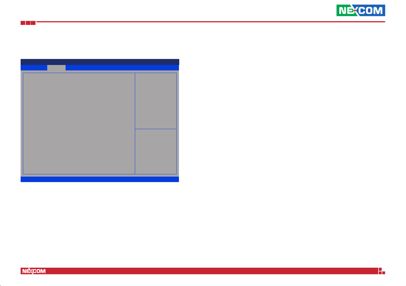
CSM Configuration
This section is used to configure the compatibility support module features.
Aptio Setup Utility - Copyright (C) 2018 American Megatrends, Inc.
Advanced
Compatibility Support Module Conguration
CSM Support
CSM16 Module Version
Boot option lter
Option ROM execution
Network
Storage
Video
Other PCI devices
Version 2.18.1263. Copyright (C) 2018 American Megatrends, Inc.
[Enabled]
07.81
[Legacy only]
[Do not launch]
[UEFI]
[Legacy]
[UEFI]
Enable/Disable CSM Support.
→←: Select Screen
↑↓: Select Item
Enter: Select
+/-: Change Opt.
F1: General Help
F2: Previous Values
F3: Optimized Defaults
F4: Save & Exit
ESC: Exit
CSM Support
This field is used to enable or disable CSM support, if Auto option is selected,
based on OS, CSM will be enabled or disabled automatically.
Storage
Controls the execution of UEFI and Legacy Storage OpROM.
Video
Controls the execution of UEFI and Legacy Video OpROM.
Other PCI Devices
Configures the OpROM execution policy for devices other than Network,
Storage or Video.
Boot Option Filter
Configures which devices the system will boot from.
Network
Controls the execution of UEFI and Legacy PXE OpROM.
Copyright © 2018 NEXCOM International Co., Ltd. All Rights Reserved.
38
NSA 5170C User Manual
Page 53
Chapter 4: BIOS Setup
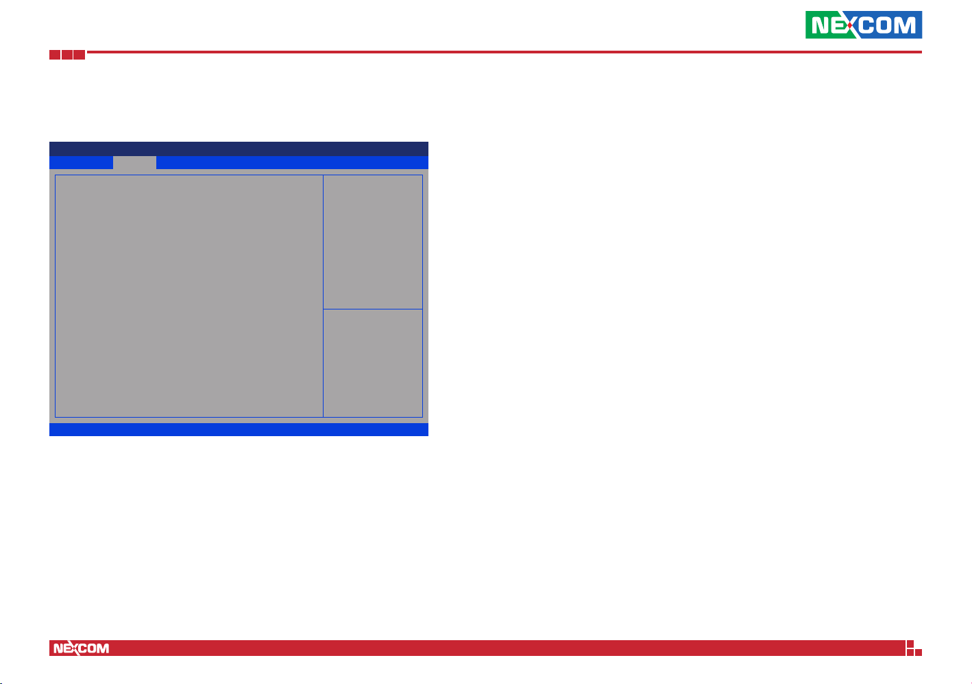
USB Configuration
This section is used to configure the USB.
Aptio Setup Utility - Copyright (C) 2018 American Megatrends, Inc.
Advanced
USB Conguration
USB Module Version
USB Controllers:
1 XHCI
USB Devices:
1 Drive, 1 Keyboard, 1 Mouse, 1 Hub
Legacy USB Support
XHCI Hand-off
USB Mass Storage Driver Support
Port 60/64 Emulation
USB hardware delays and time-outs:
USB transfer time-out
Device reset time-out
Device power-up delay
Mass Storage Devices:
KingstonDataTraveler 3.0
Version 2.18.1263. Copyright (C) 2018 American Megatrends, Inc.
19
[Enabled]
[Enabled]
[Enabled]
[Disabled]
[20 sec]
[20 sec]
[Auto]
[Auto]
Enables Legacy USB support.
AUTO option disables legacy
support if no USB devices are
connected. DISABLE option will
keep USB devices available
only for EFI applications.
→←: Select Screen
↑↓: Select Item
Enter: Select
+/-: Change Opt.
F1: General Help
F2: Previous Values
F3: Optimized Defaults
F4: Save & Exit
ESC: Exit
Legacy USB Support
Enable Enables Legacy USB.
Auto Disables support for Legacy when no USB devices are connected.
Disable Keeps USB devices available only for EFI applications.
USB Mass Storage Driver Support
Enables or disables USB mass storage device driver support.
Port 60/64 Emulation
Enables I/O port 60h/64h emulation support. This should be enabled for
complete USB keyboard legacy support for non-USB aware OS.
USB Transfer Time-out
The time-out value for control, bulk, and Interrupt transfers.
Device Reset Time-out
Selects the USB mass storage device’s start unit command timeout.
Device Power-up Delay
Maximum time the value will take before it properly reports itself to the Host
Controller. “Auto” uses default value: for a Root port it is 100 ms, for a Hub
port the delay is taken from Hub descriptor.
Mass Storage Devices
Configures the mass storage device emulation type. AUTO enumerates
devices according to their media format. Optical drives are emulated as
CDROM, drives with no media will be emulated according to a drive type.
XHCI Hand-off
This is a workaround for OSs that does not support XHCI hand-off. The
XHCI ownership change should be claimed by the XHCI driver.
Copyright © 2018 NEXCOM International Co., Ltd. All Rights Reserved.
39
NSA 5170C User Manual
Page 54
Chapter 4: BIOS Setup
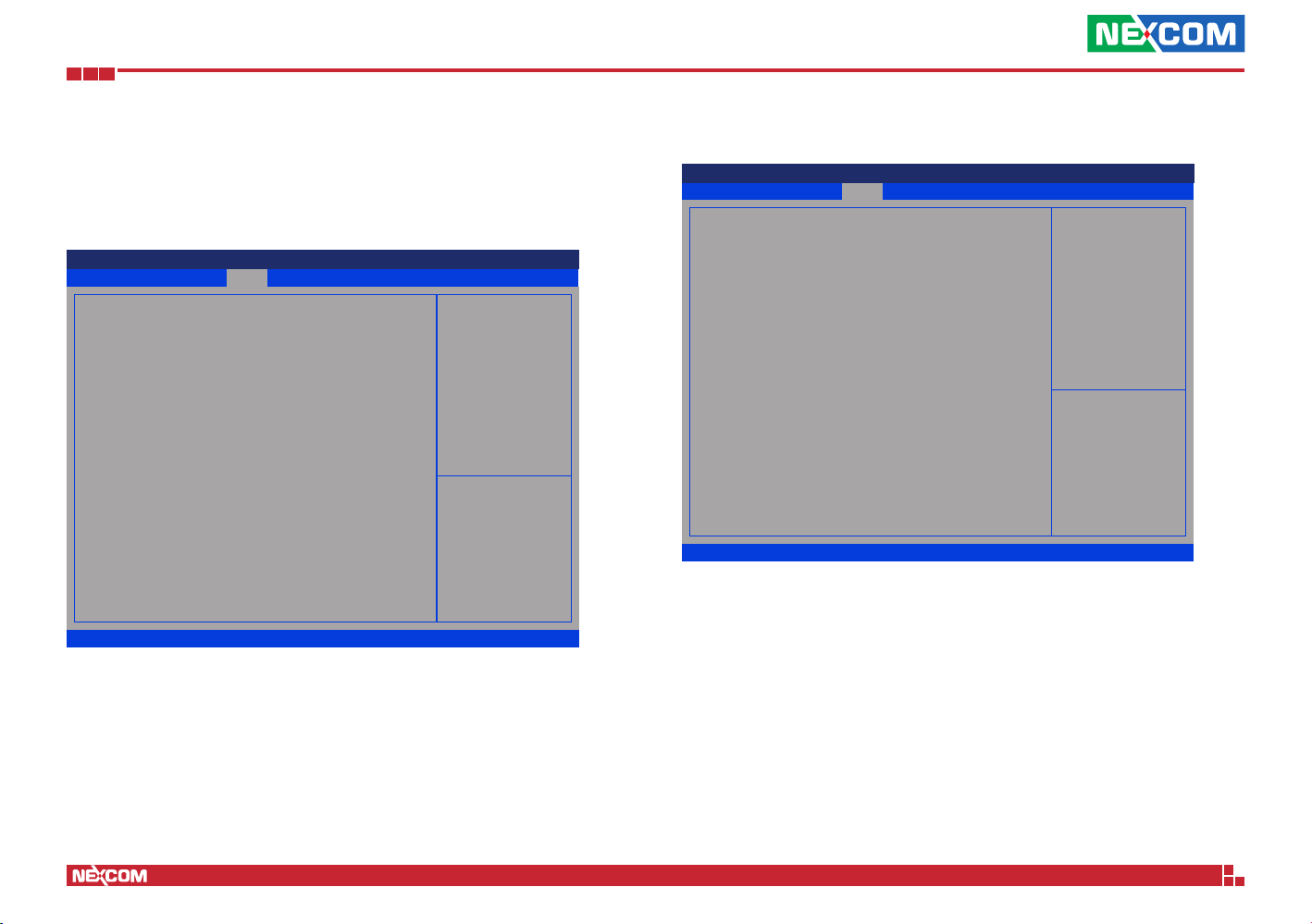
Chipset
This section gives you functions to configure the system based on the
specific features of the chipset. The chipset manages bus speeds and access
to system memory resources.
Aptio Setup Utility - Copyright (C) 2018 American Megatrends, Inc.
Save & ExitAdvanced Chipset Security BootMain
System Agent (SA) Conguration
►
PCH-IO Conguration
►
Version 2.18.1263. Copyright (C) 2018 American Megatrends, Inc.
PCH-IO Configuration
This field is used to configure PCH parameters.
System Agent (SA) Configuration
This field is used to configure System Agent (SA) parameters.
System Agent (SA) Parameters
→←: Select Screen
↑↓: Select Item
Enter: Select
+/-: Change Opt.
F1: General Help
F2: Previous Values
F3: Optimized Defaults
F4: Save & Exit
ESC: Exit
System Agent (SA) Configuration
Aptio Setup Utility - Copyright (C) 2018 American Megatrends, Inc.
Advanced Chipset Boot SecurityMain
System Agent (SA) Conguration
SA PCIe Code Version
VT-d
Memory Conguration
►
Graphics Conguration
►
PEG Port Conguration
►
VT-d
X2APIC Opt Out
Version 2.18.1263. Copyright (C) 2018 American Megatrends, Inc.
2.3.0.0
Supported
[Enabled]
[Disabled]
Memory Configuration
Configures the memory settings.
Graphics Configuration
Configures the graphics chip settings.
PEG Port Configuration
Configures the PEG Port settings.
VT-d
Enables or disables VT-d function on MCH.
Save & Exit
Memory Conguration
Parameters
→←: Select Screen
↑↓: Select Item
Enter: Select
+/-: Change Opt.
F1: General Help
F2: Previous Values
F3: Optimized Defaults
F4: Save & Exit
ESC: Exit
Copyright © 2018 NEXCOM International Co., Ltd. All Rights Reserved.
X2APIC Opt Out
Enables or disables X2APIC mode.
40
NSA 5170C User Manual
Page 55
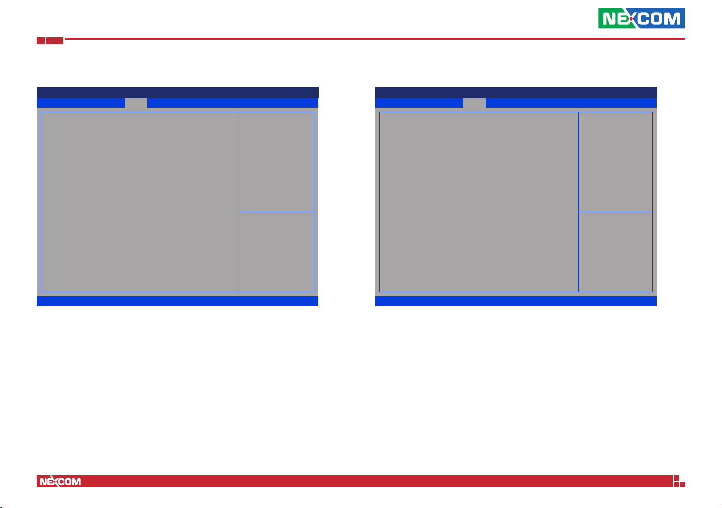
Chapter 4: BIOS Setup
Memory Configuration
Aptio Setup Utility - Copyright (C) 2018 American Megatrends, Inc.
Chipset
Memory Conguration
Memory RC Version
Memory Frequency
Memory Timings
(tCL-tRCD-tRP-tRAS)
Channel 0 Slot 0
Size
Number of Ranks
Manufacturer
Channel 0 Slot 1
Channel 1 Slot 0
Channel 1 Slot 1
Version 2.18.1263. Copyright (C) 2018 American Megatrends, Inc.
2.3.0.0
2400 Mhz
17-17-17-39
Populated & Enabled
4096 MB (DDR4)
1
UnKnown
Not Populated / Disabled
Not Populated / Disabled
Not Populated / Disabled
MRC ULT Safe Cong for PO
→←: Select Screen
↑↓: Select Item
Enter: Select
+/-: Change Opt.
F1: General Help
F2: Previous Values
F3: Optimized Defaults
F4: Save & Exit
ESC: Exit
Memory Configuration
Detects and displays information of the memory installed in the system.
Graphics Configuration
Aptio Setup Utility - Copyright (C) 2018 American Megatrends, Inc.
Chipset
Graphics Configuration
Internal Graphics
GTT Size
Aperture Size
DVMT Pre-Allocated
DVMT Total Gfx Mem
Version 2.18.1263. Copyright (C) 2018 American Megatrends, Inc.
[Auto]
[8MB]
[256MB]
[32M]
[256M]
Internal Graphics
Keep IGD enabled based on the setup options.
GTT Size
Configures the GTT memory size.
Keep IGFX enabled based on the
setup options.
→←: Select Screen
↑↓: Select Item
Enter: Select
+/-: Change Opt.
F1: General Help
F2: Previous Values
F3: Optimized Defaults
F4: Save & Exit
ESC: Exit
Copyright © 2018 NEXCOM International Co., Ltd. All Rights Reserved.
Aperture Size
Configures the Aperture size.
DVMT Pre-Allocated
Configures the DVMT 5.0 pre-allocated (fixed) graphics memory size used
by the internal graphics device.
DVMT Total Gfx Mem
Configures the DVMT 5.0 total graphic memory size used by the IGD.
41
NSA 5170C User Manual
Page 56
Chapter 4: BIOS Setup
PEG Port Configuration
Aptio Setup Utility - Copyright (C) 2018 American Megatrends, Inc.
Chipset
PEG Port Conguration
PEG 0:1:0
Enable Root Port
Max Link Speed
PEG 0:1:1
Enable Root Port
Max Link Speed
PCIe Spread Spectrum Clocking
Version 2.18.1263. Copyright (C) 2018 American Megatrends, Inc.
Not Present
[Enabled]
[Auto]
Not Present
[Enabled]
[Auto]
[Disabled]
Enable or Disable the Root Port
→←: Select Screen
↑↓: Select Item
Enter: Select
+/-: Change Opt.
F1: General Help
F2: Previous Values
F3: Optimized Defaults
F4: Save & Exit
ESC: Exit
Enable Root Port (PEG 0:1:0 and 0:1:1)
Enables or disables the root port.
Max Link Speed
(PEG 0:1:0 and 0:1:1)
Configures the maximum link speed of the PEG device.
PCH-IO Configuration
Aptio Setup Utility - Copyright (C) 2018 American Megatrends, Inc.
Chipset
PCH-IO Conguration
SATA and RST Conguration
►
NETWORK CONFIGURATION
►
State After G3
Power Supply Type
Version 2.18.1263. Copyright (C) 2018 American Megatrends, Inc.
[Last State]
ATX
SATA and RST Configuration
Enters the SATA and RST configuration sub-menu.
Network Configuration
Enters the network configuration sub-menu.
SATA Device Options Settings
→←: Select Screen
↑↓: Select Item
Enter: Select
+/-: Change Opt.
F1: General Help
F2: Previous Values
F3: Optimized Defaults
F4: Save & Exit
ESC: Exit
PCIe Spread Spectrum Clocking
Enables or disables PCIe Spread Spectrum Clocking for compliance testing.
Copyright © 2018 NEXCOM International Co., Ltd. All Rights Reserved.
State After G3
Configures the PCH state after G3.
42
NSA 5170C User Manual
Page 57
Chapter 4: BIOS Setup
SATA And RST Configuration
Aptio Setup Utility - Copyright (C) 2018 American Megatrends, Inc.
Advanced
SATA And RST Conguration
SATA Controller(s)
SATA Mode Selection
Software Feature Mask Conguration
►
Serial ATA Port 0(CF)
Software Preserve
Port 0
Spin Up Device
SATA Device Type
Topology
SATA Port 0 DevSlp
DIT0 Conguration
DIT0 Value
DM Value
Serial ATA Port 1
Software Preserve
Port 1
Hot Plug
Congured as eSATA
Spin Up Device
SATA Device Type
Version 2.18.1263. Copyright (C) 2018 American Megatrends, Inc.
Chipset
[Enabled]
[AHCI]
Empty
Unknown
[Enabled]
[Disabled]
[Hard Disk Drive]
[ISATA]
[Disabled]
[Disabled]
625
15
Empty
Unknown
[Enabled]
[Disabled]
Hot Plug supported
[Disabled]
[Hard Disk Drive]
▲
Enable/Disable SATA Device.
→←: Select Screen
↑↓: Select Item
Enter: Select
+/-: Change Opt.
F1: General Help
F2: Previous Values
F3: Optimized Defaults
F4: Save & Exit
ESC: Exit
▼
SATA Controller(s)
Enables or disables the SATA controller.
SATA Mode Selection
Configures the SATA mode. The options are AHCI and Intel RST Premium.
Port 0, Port 1, Port 2, Port 6 and Port 7
Enables or disables SATA port 0, port 1, port 2, port 3, port 6 and port 4.
Aptio Setup Utility - Copyright (C) 2018 American Megatrends, Inc.
Advanced
Topology
SATA Port 1 DevSlp
DIT0 Conguration
DIT0 Value
DM Value
Serial ATA Port 2
Software Preserve
Port 1
Hot Plug
Congured as eSATA
Spin Up Device
SATA Device Type
Topology
SATA Port 2 DevSlp
DIT0 Conguration
DIT0 Value
DM Value
Serial ATA Port 3
Software Preserve
Port 2
Hot Plug
Congured as eSATA
Spin Up Device
SATA Device Type
Topology
SATA Port 3 DevSlp
DIT0 Conguration
Version 2.18.1263. Copyright (C) 2018 American Megatrends, Inc.
Chipset
[ISATA]
[Disabled]
[Disabled]
625
15
Empty
Unknown
[Enabled]
[Disabled]
Hot Plug supported
[Disabled]
[Hard Disk Drive]
[ISATA]
[Disabled]
[Disabled]
625
15
Empty
Unknown
[Enabled]
[Disabled]
Hot Plug supported
[Disabled]
[Hard Disk Drive]
[ISATA]
[Disabled]
[Disabled]
▲
→←: Select Screen
↑↓: Select Item
Enter: Select
+/-: Change Opt.
F1: General Help
F2: Previous Values
F3: Optimized Defaults
F4: Save & Exit
ESC: Exit
▼
Hot Plug
Enables or disables hot plugging feature on SATA port 1, port 2, port 3, port
6 and port 4.
Spin Up Device
Enables or disables staggered spin up on devices connected to SATA port 0,
port 1, port 2, port 3, port 6 and port 4
SATA Device Type
Identifies what type of SATA device is connected.
Copyright © 2018 NEXCOM International Co., Ltd. All Rights Reserved.
43
NSA 5170C User Manual
Page 58
Chapter 4: BIOS Setup
SATA And RST Configuration Cont.
Aptio Setup Utility - Copyright (C) 2018 American Megatrends, Inc.
Advanced
DIT0 Value
DM Value
Serial ATA Port 6(CN6)
Software Preserve
Port 6
Hot Plug
Congured as eSATA
Spin Up Device
SATA Device Type
Topology
SATA Port 6 DevSlp
DIT0 Conguration
DIT0 Value
DM Value
Serial ATA Port 4
Software Preserve
Port 7
Hot Plug
Congured as eSATA
Spin Up Device
SATA Device Type
Topology
SATA Port 7 DevSlp
DIT0 Conguration
DIT0 Value
DM Value
Version 2.18.1263. Copyright (C) 2018 American Megatrends, Inc.
Chipset
625
15
Empty
Unknown
[Enabled]
[Disabled]
Hot Plug supported
[Disabled]
[Hard Disk Drive]
[Unknown]
[Disabled]
[Disabled]
625
15
Empty
Unknown
[Enabled]
[Disabled]
Hot Plug supported
[Disabled]
[Hard Disk Drive]
[Unknown]
[Disabled]
[Disabled]
625
15
▲
→←: Select Screen
↑↓: Select Item
Enter: Select
+/-: Change Opt.
F1: General Help
F2: Previous Values
F3: Optimized Defaults
F4: Save & Exit
ESC: Exit
▼
Topology
Identifies what type of SATA connection is used.
SATA Port 0, Port 1, Port 2, Port 3, Port 6 and Port 4 DevSlp
Enables or disables SATA Port 0, Port 1, Port 2, Port 3, Port 6 and Port 4
DevSlp. Before enabling DevSlp, board rework is needed.
DIT0 Configuration
Enables or disables DIT0 configuration for SATA Port 0, Port 1, Port 2, Port
3, Port 6 and Port 4.
Network Configuration
Aptio Setup Utility - Copyright (C) 2018 American Megatrends, Inc.
Chipset
Slot1 Model Name:
Slot2 Model Name:
Slot3 Model Name:
Slot4 Model Name:
Slot5 Model Name:
Slot6 Model Name:
Slot7 Model Name:
Slot8 Model Name:
ByPass Auto Detect
Power_ON ByPass Mode
Power_OFF ByPass Mode
Version 2.18.1263. Copyright (C) 2018 American Megatrends, Inc.
Device is Not Found
Device is Not Found
Device is Not Found
Device is Not Found
Device is Not Found
Device is Not Found
Device is Not Found
Device is Not Found
[Enabled]
[Disabled]
[Disabled]
Switch ByPass Auto Detect to
Enable/Disable
→←: Select Screen
↑↓: Select Item
Enter: Select
+/-: Change Opt.
F1: General Help
F2: Previous Values
F3: Optimized Defaults
F4: Save & Exit
ESC: Exit
ByPass Auto Detect
Enables or disables automatic LAN Bypass function.
Power_ON ByPass Mode
Enables or disables the LAN module bypass mode after the system powers on.
Power_OFF ByPass Mode
Enables or disables the LAN module bypass mode after the system powers off.
Copyright © 2018 NEXCOM International Co., Ltd. All Rights Reserved.
44
NSA 5170C User Manual
Page 59
Chapter 4: BIOS Setup
Boot
This section is used to configure the boot features.
Aptio Setup Utility - Copyright (C) 2018 American Megatrends, Inc.
Boot Conguration
Setup Prompt Timeout
Bootup NumLock State
Boot mode select
FIXED BOOT ORDER Priorities
Boot Option #1
Boot Option #2
Boot Option #3
Boot Option #4
Boot Option #5
Boot Option #6
Boot Option #7
Boot Option #8
Version 2.18.1263. Copyright (C) 2018 American Megatrends, Inc.
Setup Prompt Timeout
Selects the number of seconds to wait for the setup activation key.
65535(0xFFFF) denotes indefinite waiting.
Security
1
[On]
[LEGACY]
[Hard Disk]
[CD/DVD]
[USB Hard Disk]
[USB CD/DVD]
[USB
Key:KingstonDataTraveler
3.0]
[USB Floppy]
[USB Lan]
[Network]
BootMain
Save & ExitAdvanced Chipset
Number of seconds to wait for
setup activation key. 65535
(0xFFFF) means indenite
waiting.
→←: Select Screen
↑↓: Select Item
Enter: Select
+/-: Change Opt.
F1: General Help
F2: Previous Values
F3: Optimized Defaults
F4: Save & Exit
ESC: Exit
Boot Mode Select
Configures the boot mode option.
Fixed Boot Order Priorities
Adjust the boot sequence of the system. Boot Option #1 is the first boot
device that the system will boot from, next will be #2 and so forth.
Bootup NumLock State
This allows you to determine the default state of the numeric keypad. By
default, the system boots up with NumLock on wherein the function of the
numeric keypad is the number keys. When set to Off, the function of the
numeric keypad is the arrow keys.
Copyright © 2018 NEXCOM International Co., Ltd. All Rights Reserved.
45
NSA 5170C User Manual
Page 60
Chapter 4: BIOS Setup
Save & Exit
Aptio Setup Utility - Copyright (C) 2018 American Megatrends, Inc.
Save & ExitAdvanced Chipset Security BootMain
Save Options
Save Changes and Reset
Discard Changes and Reset
Default Options
Restore Defaults
Boot Override
KingstonDataTraveler 3.0
Launch EFI Shell from lesystem device
Version 2.18.1263. Copyright (C) 2018 American Megatrends, Inc.
Save Changes and Reset
To save the changes and reset, select this field then press <Enter>. A dialog
box will appear. Confirm by selecting Yes.
Exit system setup after saving
the changes.
→←: Select Screen
↑↓: Select Item
Enter: Select
+/-: Change Opt.
F1: General Help
F2: Previous Values
F3: Optimized Defaults
F4: Save & Exit
ESC: Exit
Boot Override
To bypass the boot sequence from the Boot Option List and boot from a
particular device, select the desired device and press <Enter>.
Launch EFI Shell From Filesystem Device
To launch EFI shell from a filesystem device, select this field and press
<Enter>.
Discard Changes and Reset
To exit the Setup utility and reset without saving the changes, select this field
then press <Enter>. You may be prompted to confirm again before exiting.
Restore Defaults
To restore the BIOS to default settings, select this field then press <Enter>. A
dialog box will appear. Confirm by selecting Yes.
Copyright © 2018 NEXCOM International Co., Ltd. All Rights Reserved.
46
NSA 5170C User Manual
 Loading...