

Page 1
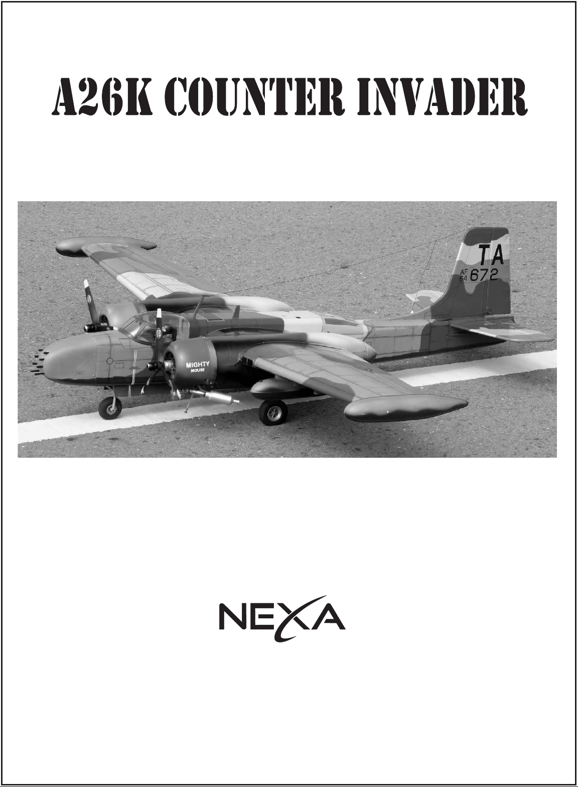
Radio control model / RC Motorflugmodell
WARNING: This radio control model is not a toy. If modifier or flow carelessly, it could go out of
control and cause serious bodily injury or propety damage, It is you responsi-bility to build this kit
correctly, to properly install all components and to seek the help of an experi-enced R/C pilot for a
pre-flight safety inspection and test flying
Achtung: Dieses Modell ist kein Spielzeug!
Sollten Sie mit solch motorisiertem Modell keine Erfahrung haben, wenden
Sie sich bitte an erfahrene Modellflieger, die Sie unterstützen können.
Es könnte zu Verletzungen kommen, wenn das Modell ohne Vorkenntnisse
in Betrieb genommen wird. Denken Sie immer an die Sicherheit und Ihre Gesundheit.
WINGSPAN: 68.in. / SPANNWEITER: 1730mm
ASSEMBLY INSTRUCTION / AUFBAUANLEITUNG
TWIN .25 - .32 CLASS - 2 CYCLE ENGINE
TWIN .40 - .52 CLASS - 4 CYCLE ENGINE
ZWEITAKTMOTOREN: 4 - 5.2cc (X2)
VIERTAKTMOTOREN : 6.5 - 8.5cc (X2)
Page 2
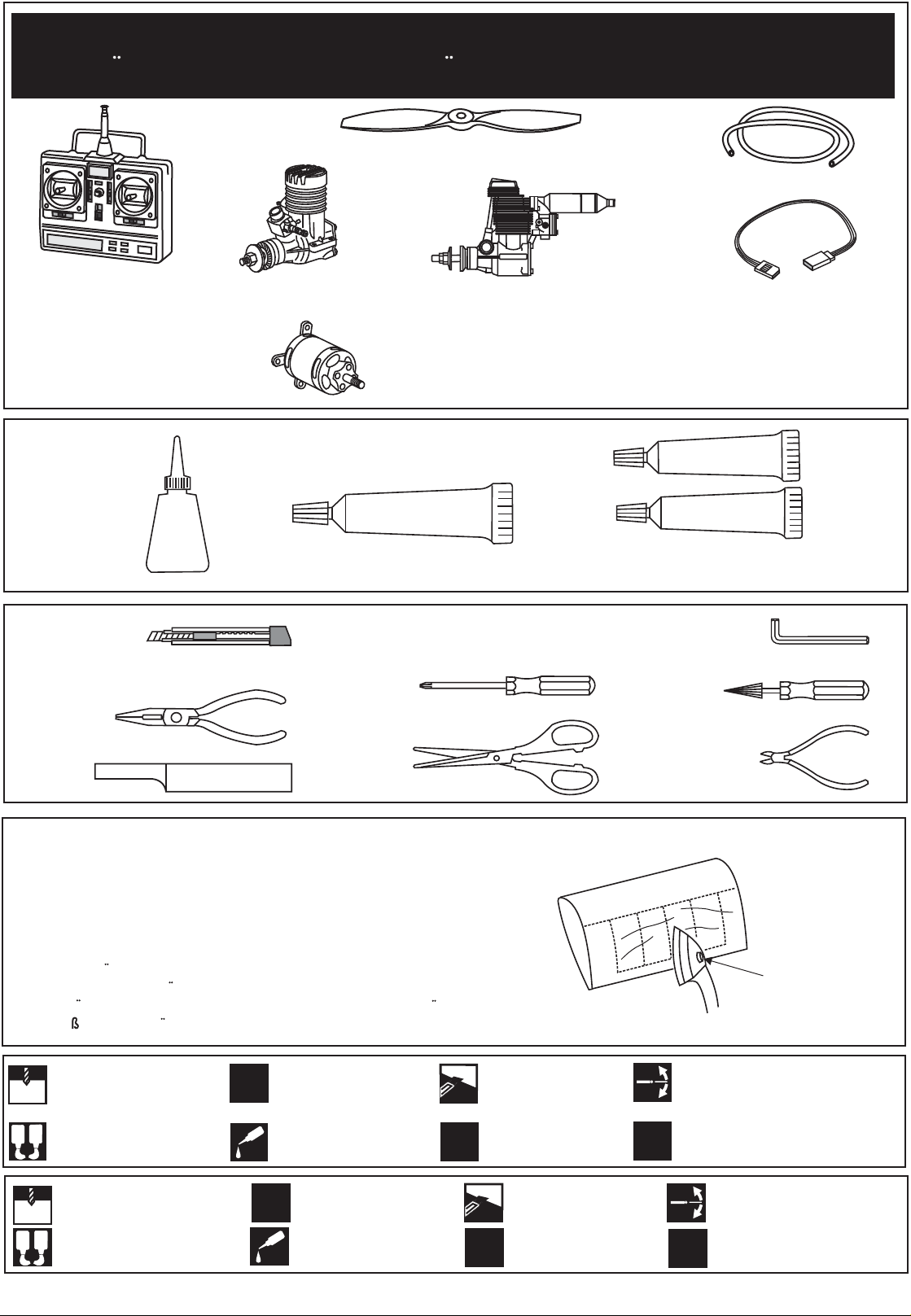
REQUIRED FOR OPERATION (Purchase separately)
BENOTIGTE KOMPONENTEN FUR DEN ABFLUG (Nicht enthalten)
9 x 7 for .32 - 2 cycle engine (x2)
10x7 for .52 - 4 cycle engine (x2)
Silicone tube
Minimum 7 channel radio
for airplane / 6 servos.
Throttle servo x2, Aileron servo x 2
Rudder servo x 1, Elevator x 1
Minimum 7 Kanal
Fernsteuerung / 6 servos.
Cyanoacrylate Glue
Klebstoff
CA
Hobby knife
Teppichmesser
Needle nose Pliers
Nadelzange
Sander
Pfeile
.........................................................
.........................................................
.........................................................
.........................................................
.........................................................
.........................................................
.........................................................
.........................................................
.........................................................
.........................................................
.........................................................
.25 ~ .32 cu.in. (X2)
4 ~ 5.2 cc (x2)
400Watt
Brushless motor (x2)
SILICON
Silicon sealer
Phillip screw driver
Kreuzschlitz-
schraubenzieher
Scissors
Schere
.40 ~ .52 cu.in. (X2)
6.5 ~ 8.5cc (x2)
Extension cord x 4
Servoverlangerungskabe x 4l
EPOXY A
EPOXY B
Epoxy Glue (30 minutes type)
Epoxy-Klebstoff (30min-Typ)
Hex Wrench
Awl
Pfriem
Wire Cutters
Kneiftzange
The pre-covered film on ARF kit may wrinkle due to variations
of temperature. Smooth out as explained right.
* Use an iron or heat gun. Start as low setting. Increase the
setting if necessary. If it is too high, you may damage the
film.
Die Bespannung des ARF-Kits kann je nach Temperatur Falten
werfen. Glatten Sie diese, wie rechts auf der Abbildung ersichtlich.
Benutzen Sie ein Bugeleisen. Starten Sie in einer niedrigen Stufe,
un erhohen Sie diese nur wenn notwendig. Wenn das Bugeleisen
zu hei wird, beschadigen Sie die Bespannung.
Drill holes using the stated
1.5mm
size of drill
Take particular care here
!
(in this case 1.5 mm Ø)
A
B
Use epoxy glue
Löcher bohren mit dem ange-
gebenen Bohrer (hier 1,5 mm)
1.5mm
A
B
Epoxy-Klebstoff verwenden
Apply cyano glue
CA
Hier besonders aufpassen
!
Sekundenkleber auftragen
CA
L/R
2
Hatched-in areas:
remove covering
film carefully
Assemble left and right
sides the same way.
Schraffierte Stellen,
Bespannfolie vorsichtig
entfernen
Linke und rechte Seite
wird gleichermaßen
L/R
zusammengebaut
Low setting
Niedrige Stufe
Check during assembly that these
parts move freely, without binding
Not included.
These parts must be
X
purchased separately
Während des Zusammenbaus
immer prüfen, ob sich die Teile
auch reibungslos bewegen lassen
Nicht enthalten. Teile müssen
separat gekauft werden.
X
Page 3
Wing halves - Top view
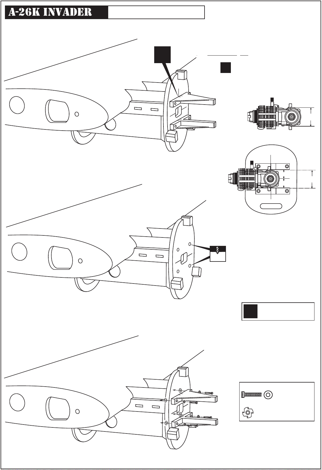
Wing: Engine mounts
!
Attach the engine mount beams onto the fire-wall
so the distance between of two engine mount beams
is “A”,and B=B’ as show.
Secure the engine mount beams onto the fire-wall
with litter CA glue (1B)
Align the mark on both engine mount
!
beams with the mark on the fuselage
Using a pencil or felt tipped pen, mark
the fire wall where the four holes are to
be drilled.
A
FRONT-VIEW
B
B’
6mm
Carefully remove the engine mount beams
and drill a 6mm hole through the fire-wall
at each of the four marks made above.
Assemble left and right
L/R
wings the same way.
A
B=B’
4x20mm screw - washer
...................4
Blind-nut
....................4
Insert the blind-nut onto each
of the four holes make above.
Reposition the engine mount beams on to the fire-wall
and secure them with four 4x25mm screw.
3
Page 4
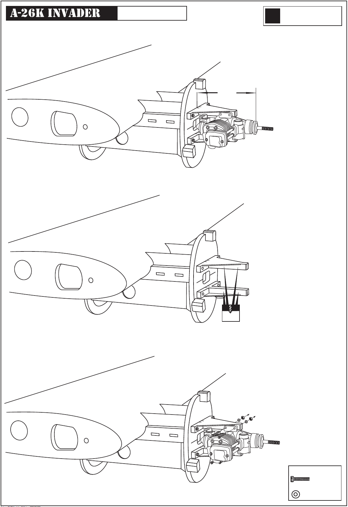
Wing: Engine
Assemble left and right
L/R
wings the same way.
Position the engine to the engine mounts so the
distance from the prop hub to the fire-wall is
86mm.
Mark the engine mounting plate where the four
holes are to be drilled.
86mm
Remove the engine and drill a 3mm holes
through the beam at each of the four marks
made above.
3mm
Marking sure that you drill the hole perpendicular
to the beam of the engine mount.
Reposition the engine on the engine mount
beams, aligning it with the holes. Secure the
engine to the engine mount using four
3x25mm screws.
Note: Apply Silicon sealer to each of the
3x25mm screw and nut.
3x25mm screw
.......4
Washer
.......4
4
Page 5
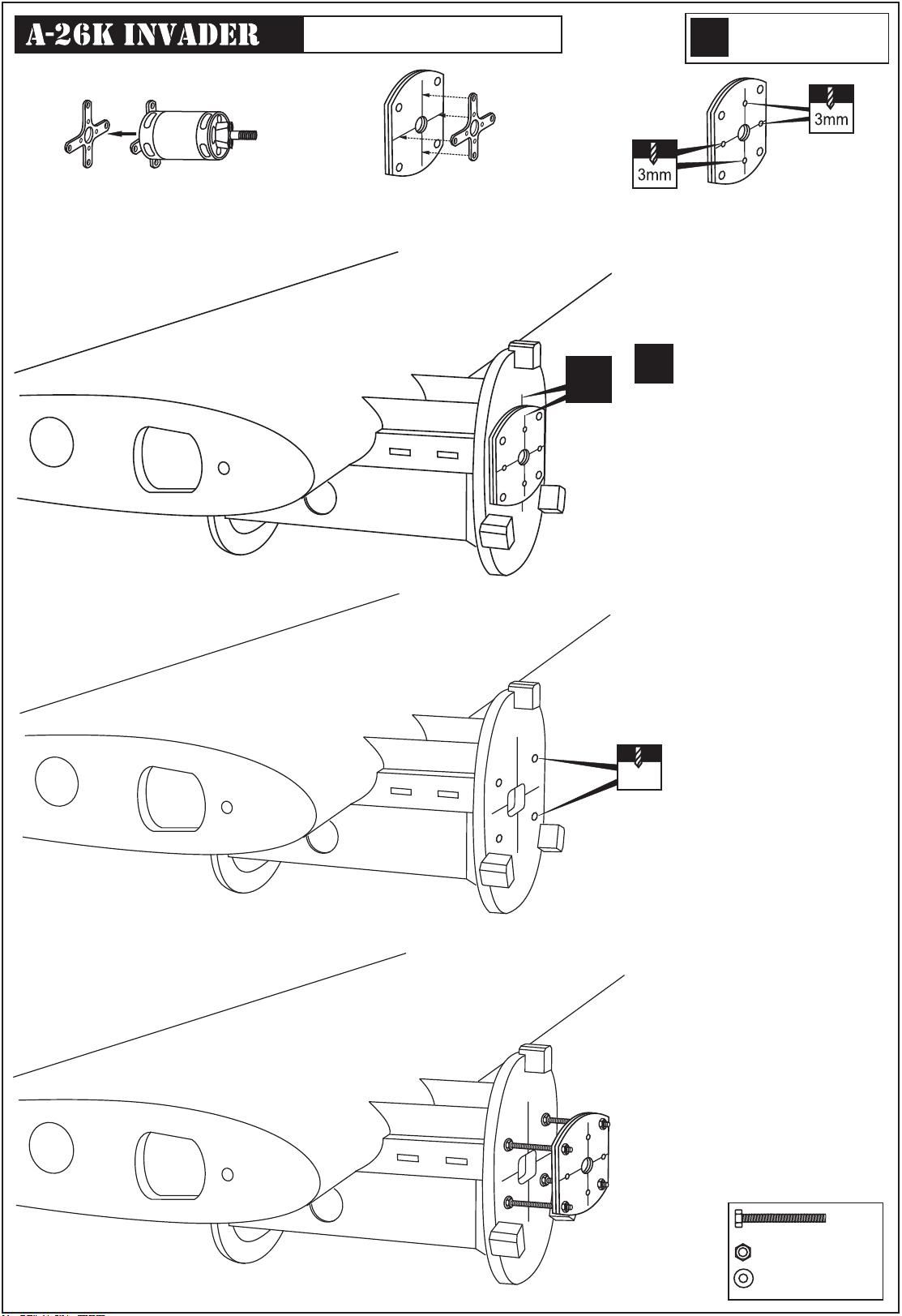
Wing: Electric motor
Using a aluminum motor mounting plate
as a template, mark the plywood motor
mounting plate where the four holes are
to be drilled.
Assemble left and right
L/R
wings the same way.
Remove the aluminum motor mounting
plate and drill a 1/8”(3mm) hole through
the plywood at each of the four marks
marked .
Align the mark on wooden motor
mounting plate with the mark on
!
the fire-wall.
!
Using a wooden motor mounting plate as a
template, mark the fire-wall where the four
holes are to be drilled.
Wing halves - Top view
5mm
Remove the wooden motor mounting
plate and drill a 5mm hole through
the fire-wall at each of the four marks
marked .
Attach the four 5x70mm bolts
and nuts to the fire-wall as shown.
5x80mm bolts.....8
5mm nut..........24
5mm washer...32
5
Page 6
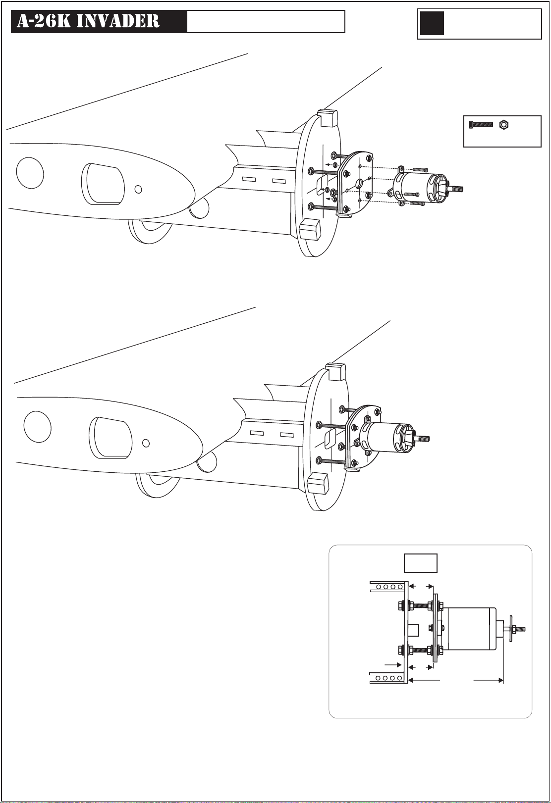
Wing: Electric motor
Assemble left and right
L/R
wings the same way.
Secure the Motor to the wooden
motor mounting plate using the
four 3mm bolts.
3mm bolt / nut...4
Adjust the 5x80mm bolts so that the distance from the fire-wall
to the hub of motor is 86mm as show.
B=B’
B
Firewall
Motorspant
TOP-VIEW / Seitenansicht
B’
86mm
6
Page 7
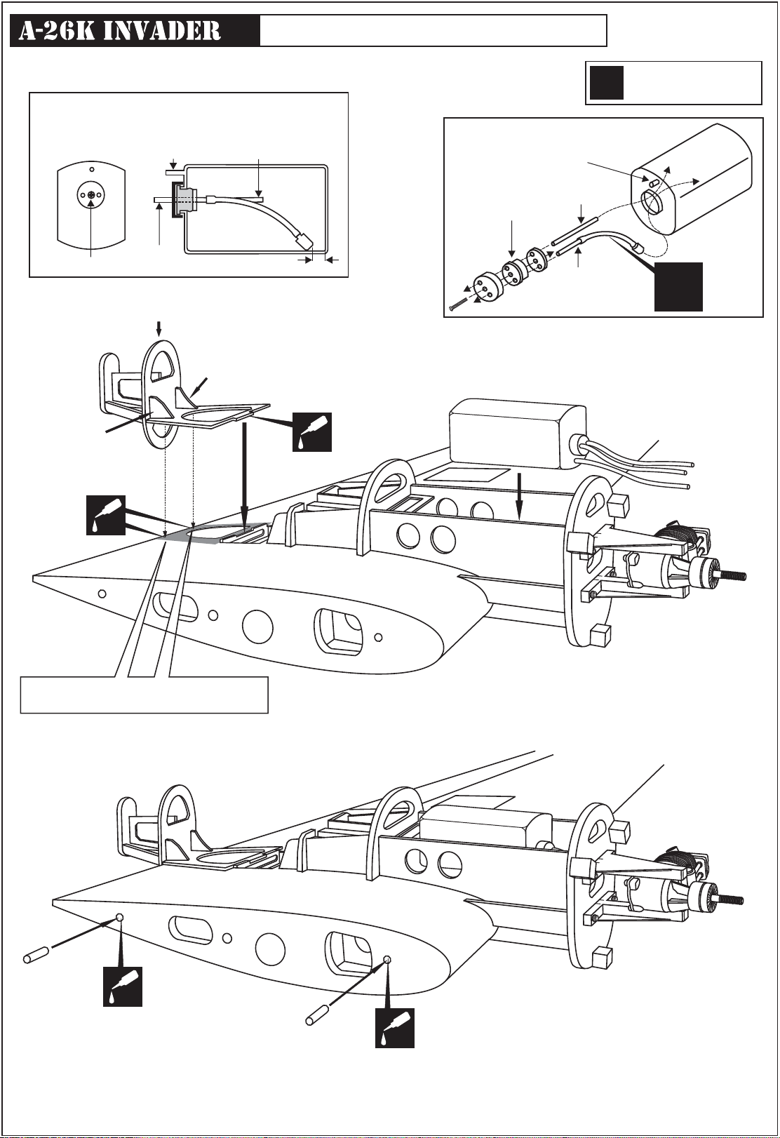
Wing: Fuel tank - Frame - Dowel
After confirming the direction . Insert this
assembly, clunk end first, into the fuel tank
and tighten and screw the fuel tank cap on
firmly.
Überlauf
Filler tube /
Tanken
To muffler/
L/R
Überlauf
Assemble left and right
wings the same way.
zum Motor
3x35 mm screw
Rear motor mount frame
B4B
CA
4mm
Note: The rear motor mount frame
has left and right sides diffrently
The bulge below the
B4A
B4A and B4B always
facing to the bottom
of the wing.
CA
Filler tube /
Rubber stopper
3x35mm screw / schraube
Tanken
To engine
zum Motor
Wing halves - Bottom view
X
These two slots are already cut at facrory
wooden dowel
CA
wooden dowel
Push the wooden dowel to the hole on the rib
as show. Ensure that the dowel is rectangular
with the rib.
Secure it in place using the thin CA glue.
CA
7
Page 8
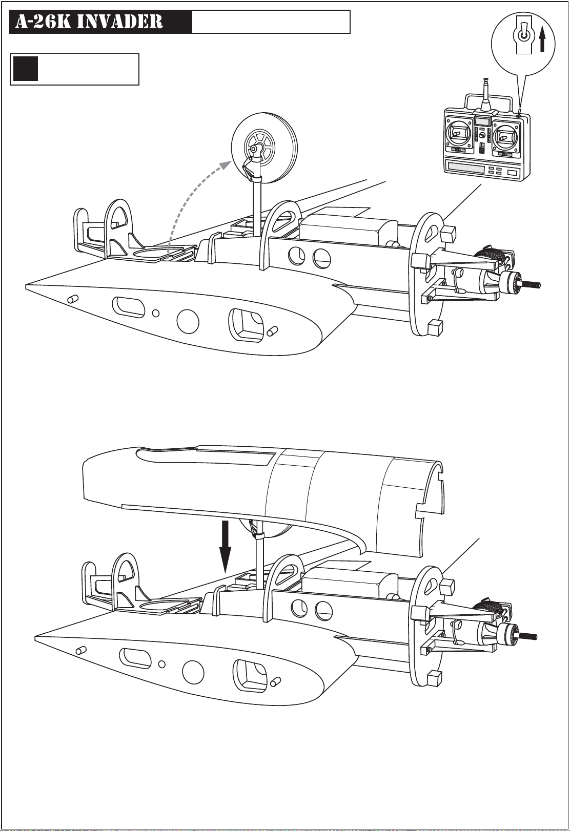
Assemble left and right
L/R
wings the same way.
Wing: Plastic shield
ON
OFF
GEAR
SWITCH
Wing halves - Bottom view
8
Page 9
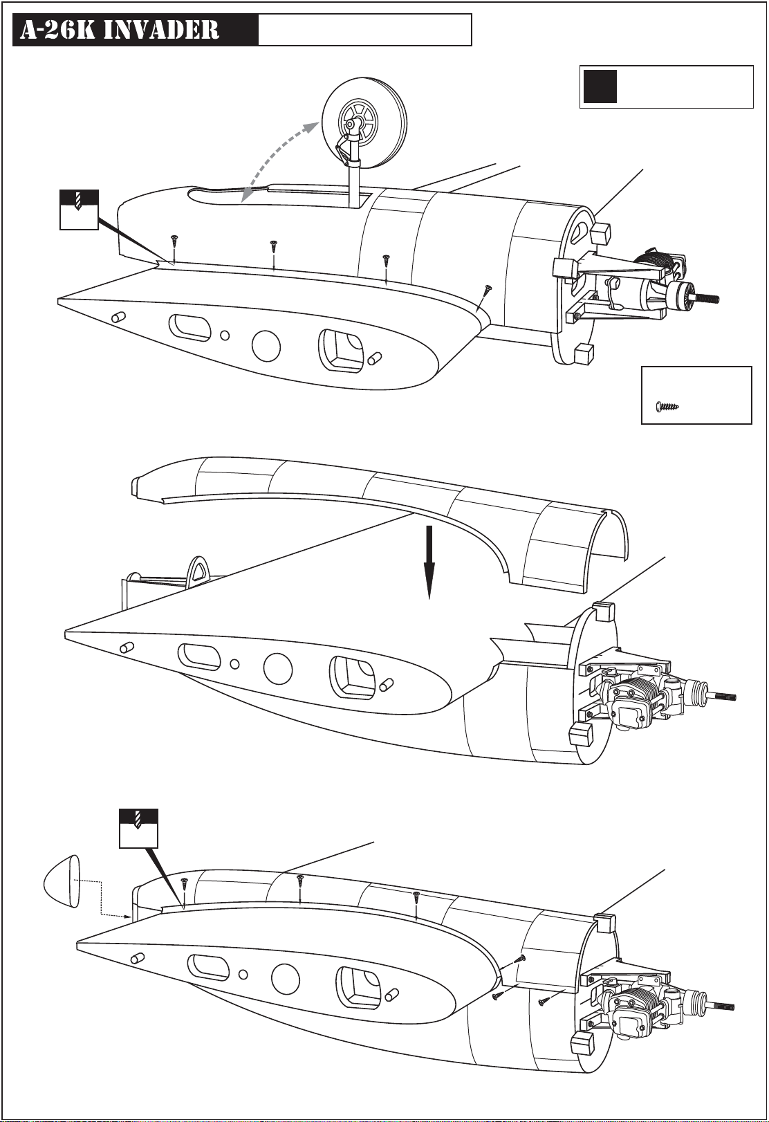
1mm
Wing: Plastic shield
Assemble left and right
L/R
wings the same way.
2x8mm screw
......46
1mm
9
Page 10
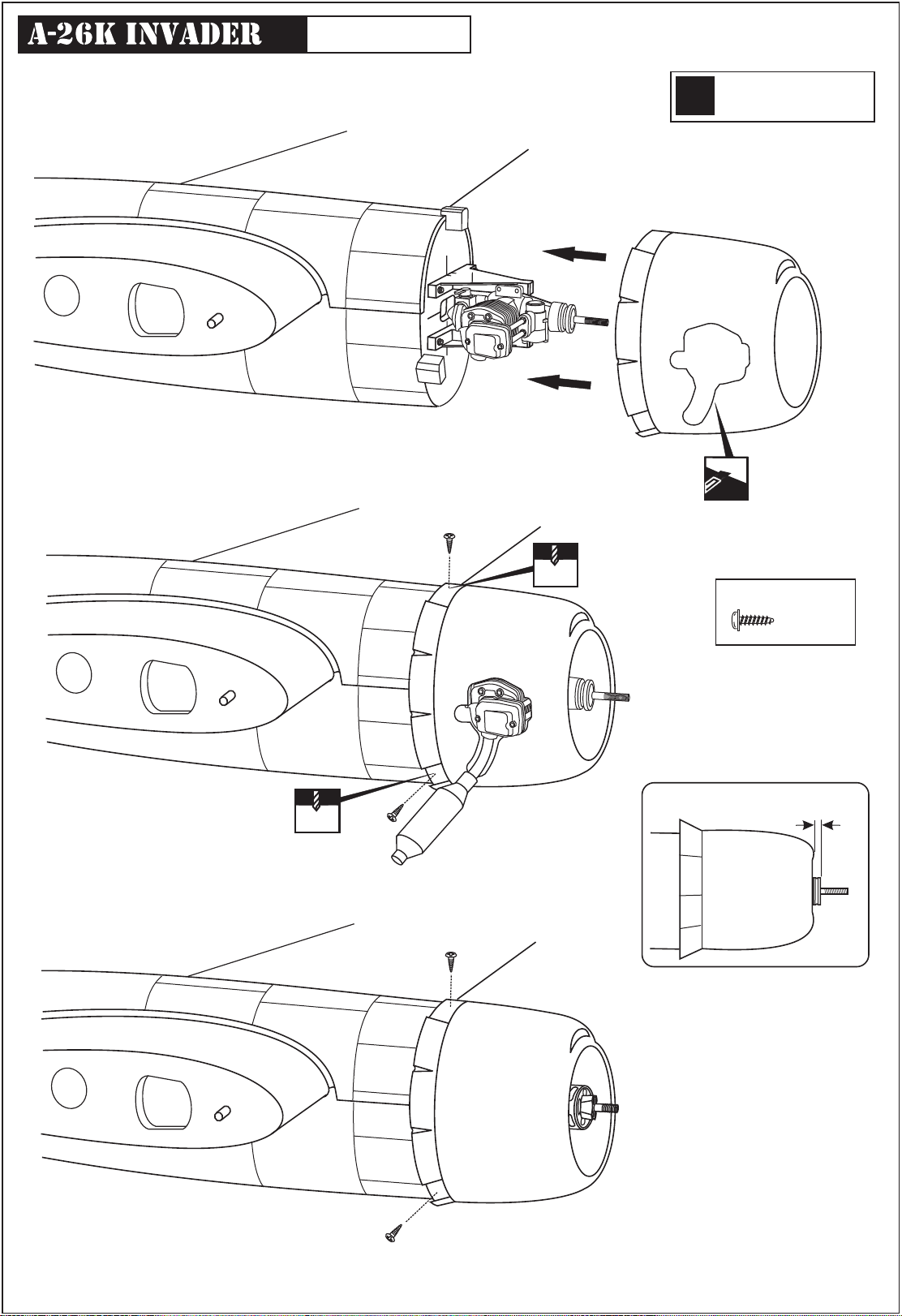
Wing: Cowl
Assemble left and right
L/R
wings the same way.
1.5mm
Cut the opening
1.5mm
2.5x10mm screw
............6
Glow engine
3 ~ 5 mm
10
Electric motor
Page 11
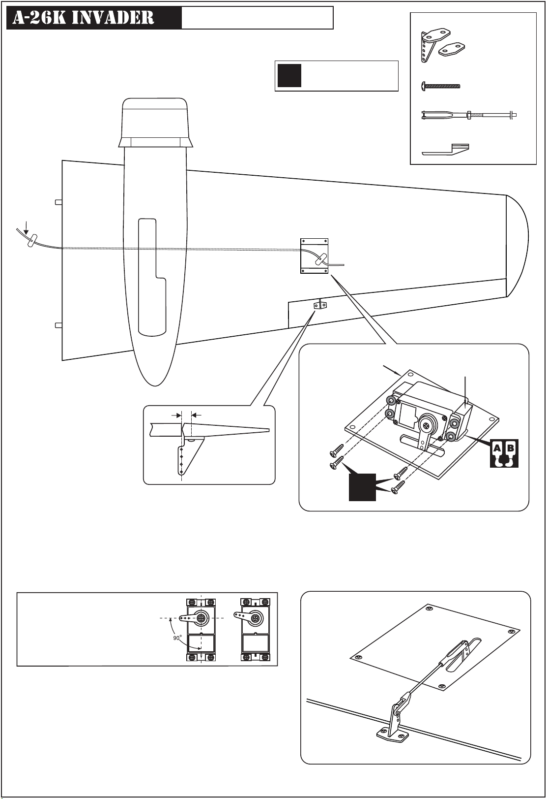
Wing: Aileron servo
Plastic control horn
Use the fishing line inside each wing to lead the aileron
servo extension cord all through the wing.
Fishing line
Assemble left and right
L/R
wings the same way.
WING - BOTTOM VIEW
UNTERSICHT
To Aileron servo extension cord
............................2
2x15mm screw
...................4
Aileron pushrod - Kwik-link
............................2
EZ-link
..................2
-Switch on the radio (trims centered)
Then mount the ailerons servo horn
In neutral position.
-The servo horn should be
Perpendicular to the servo
10mm
Aileron servo hatch
Servo mount
X
Aileron servo installation - Bottom view
Step 2A
YES
NO
Aileron linkage
11
Page 12
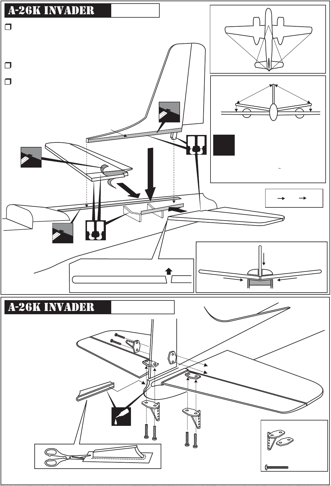
Stabilizer
Trial fit each part before gluing . Be certain
that there are no gaps. If the parts will join,
but with a gaps, sand or trim the parts a
little at a time until the parts meet exactly
with no gaps.
When joining the stabilizer it is extremely
important to use plenty of epoxy (30 minutes)
Carefully slide the stabilizer onto the fuselage,
ensuring that they are accurately aligned,
Firmly press they are together, allowing the
excess epoxy run out. Using rubbing alcohol
and paper towel, clean off the excess
epoxy.
Cut away only the
covering both side
L/R
3
C
=
C’
B
D
C
A
A=A’
D’
C’
A’
B=B’
D
=
D’
B’
Cut away only the
covering both side
Schraffierte Stellen,
Bespannfolie vorsichtig
entfernen
Schraffierte Stellen,
Bespannfolie vorsichtig
entfernen
1
A
B
HORIZONTAL STABILIZER
Control horn
TOP
BOTTOM
A
B
2
Horizontal tail
Securely glue together. If
coming off during flights.
!
You lose control of your plane
Vergewissern Sie sich, sauber geklebt
zu haben Andernfalls konnen Probleme
mit der Flugeigenschaft auftreten !
3
Fin
1
2
Horizontal tail
Fuselage
CA
12
5/64x31/64” screw
2x12mm schraube
Plastic control horn
...............3
5/64x31/64” screw
2x12mm schraube
....................6
Page 13
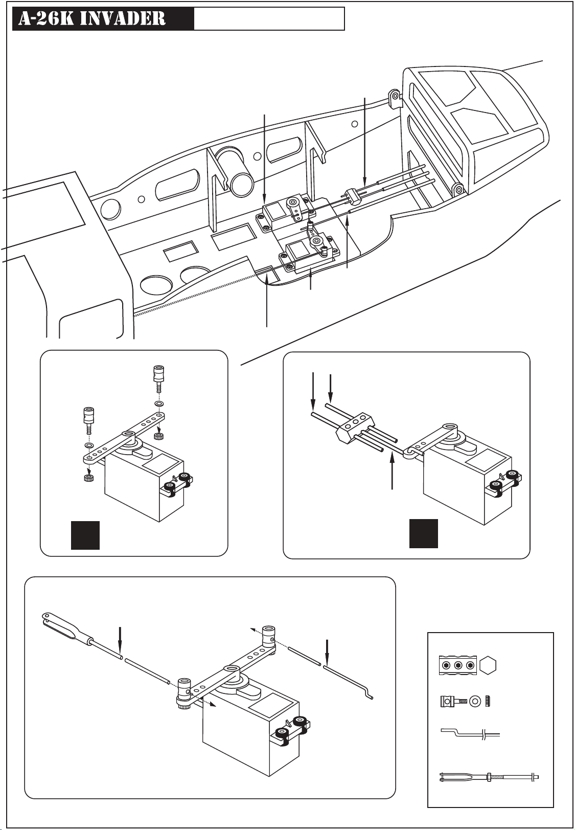
Servo and linkages
Note: You can attach the nose gear servo at the nose or middle of the fuselage
depending on your plane is heavy or light in the nose. (See page 14).
Elevator pushrod
Elevator servo
Höhenruderservo
Rudergestänge
Rudder servo
Seitenruderservo
Rudder pushrod
Connector
Connector
X
Rudder servo
2x950mm Rudder pushrod
Nose gear pushrod
950mm Elevator pushrod with Kwik-link one end
Connector
100mm Elevator pushrod
with Z bend one end
Elevator servo
X
1.2x550mm nose gear
pushrod
Connector
Rudder servo
.........1
Connector
.........2
1.2x550mm pushrod
.........1
2x950mm pushrod with
Kwik-link one end
.........3
13
Page 14
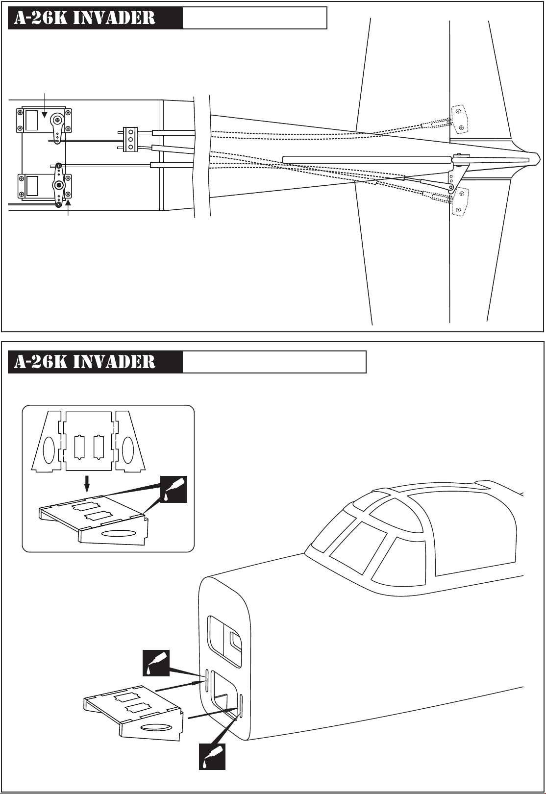
Servo and linkages
Elevator servo
Höhenruderservo
N
FUSELAGE - TOP VIEW / AUFSICHT
E1
E2
R
Rudder servo
Seitenruderservo
Elevator pushrod:
E2&E1
Höhenruderservo :
Rudder pushrod:
R
Seitenruderservo :
Nose gear pushrod:N
E1
R
E2
E2&E1
R
Nose gear servo mount
Note: Install the nose gear servo mount in case of your model lightly
the nose even the nose gear extended position.
CA
CA
CA
14
Page 15
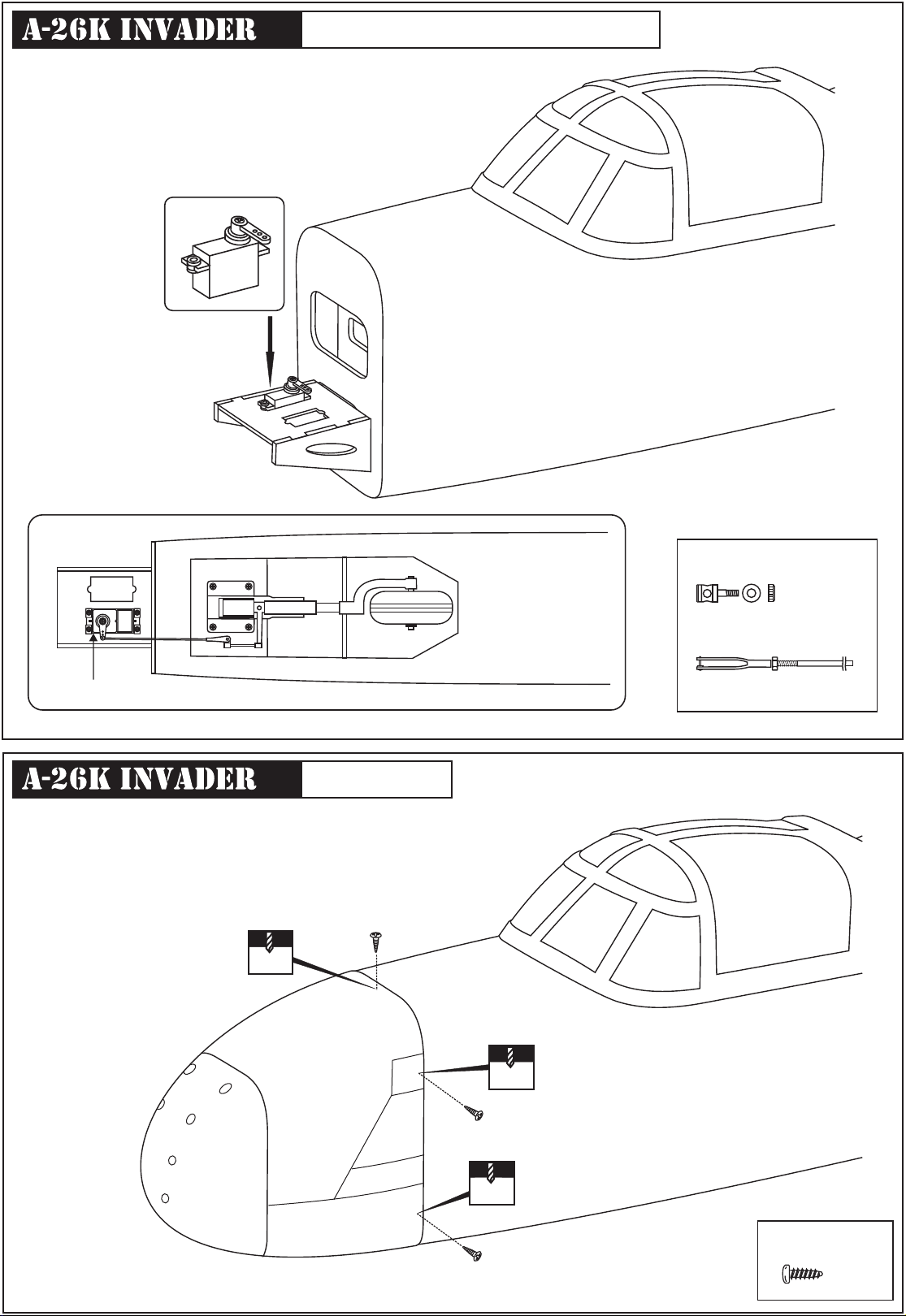
Nose gear servo and linkage
Nose gear servo
Connector
.........1
Fuselage - Bottom view
2x175mm pushrod with
Kwik-link one end
.........1
Nose cowl
1.5mm
15
1.5mm
1.5mm
2x8mm screw
........6
Page 16
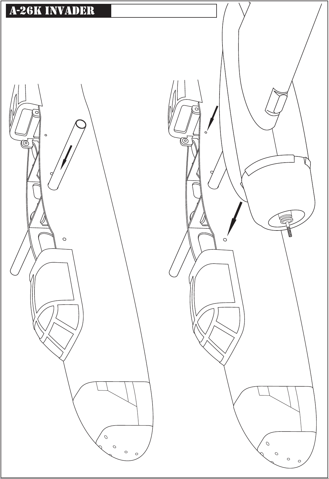
Joining the wing halves
16
Page 17
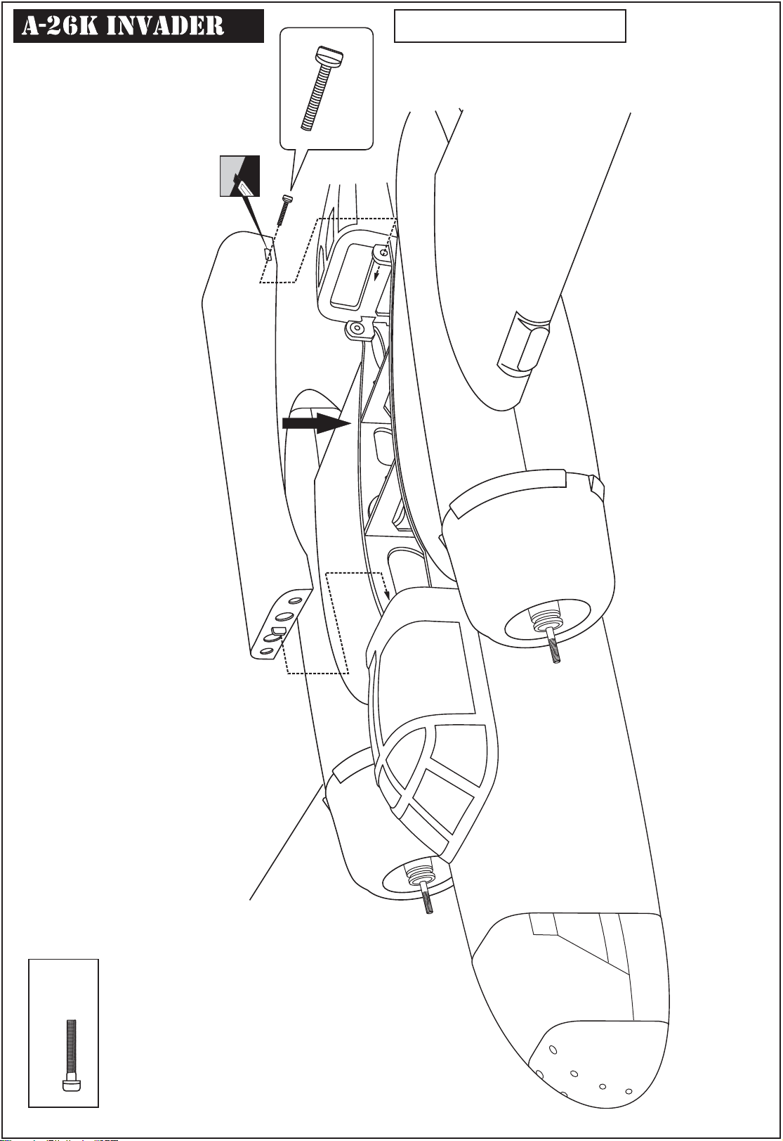
Cut away only the covering
Fuselage: Top hatch
4x30mm nylon screw
......2
4x20mm nylon screw
17
Page 18
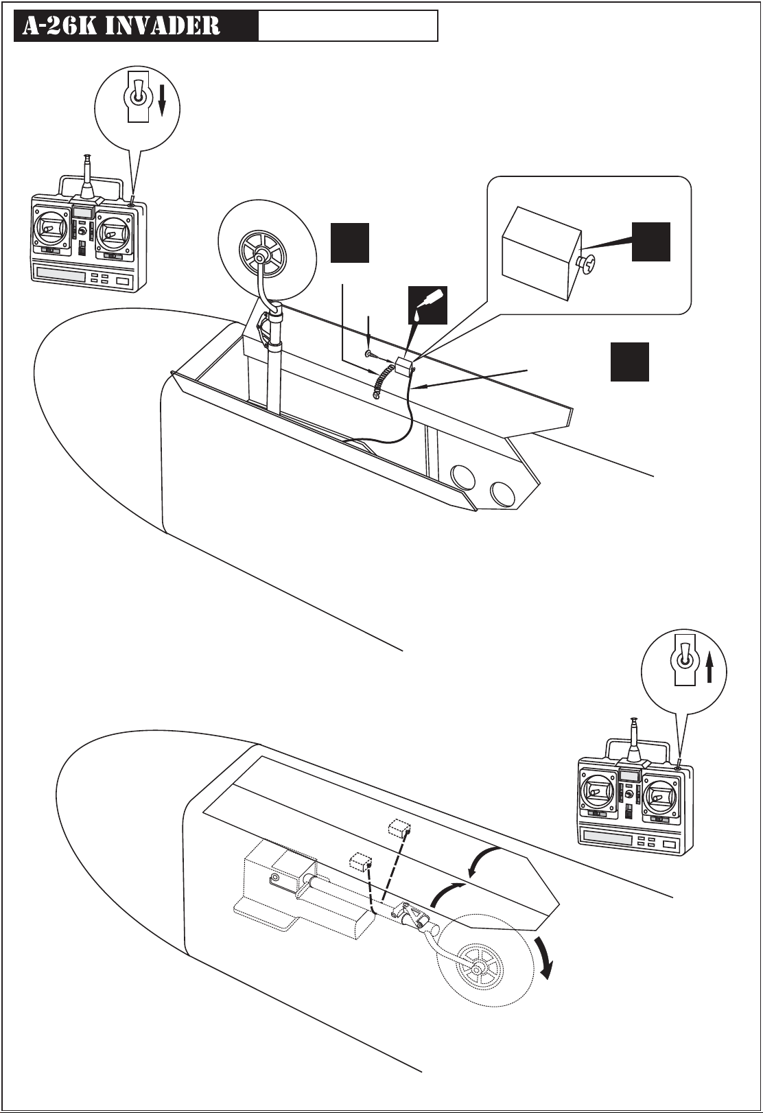
ON
OFF
GEAR
SWITCH
Nose gear door
Balsa block
X
Spring
3mm
screw
CA
Cotton thread
X
2mm screw
X
ON
OFF
GEAR
SWITCH
18
Page 19
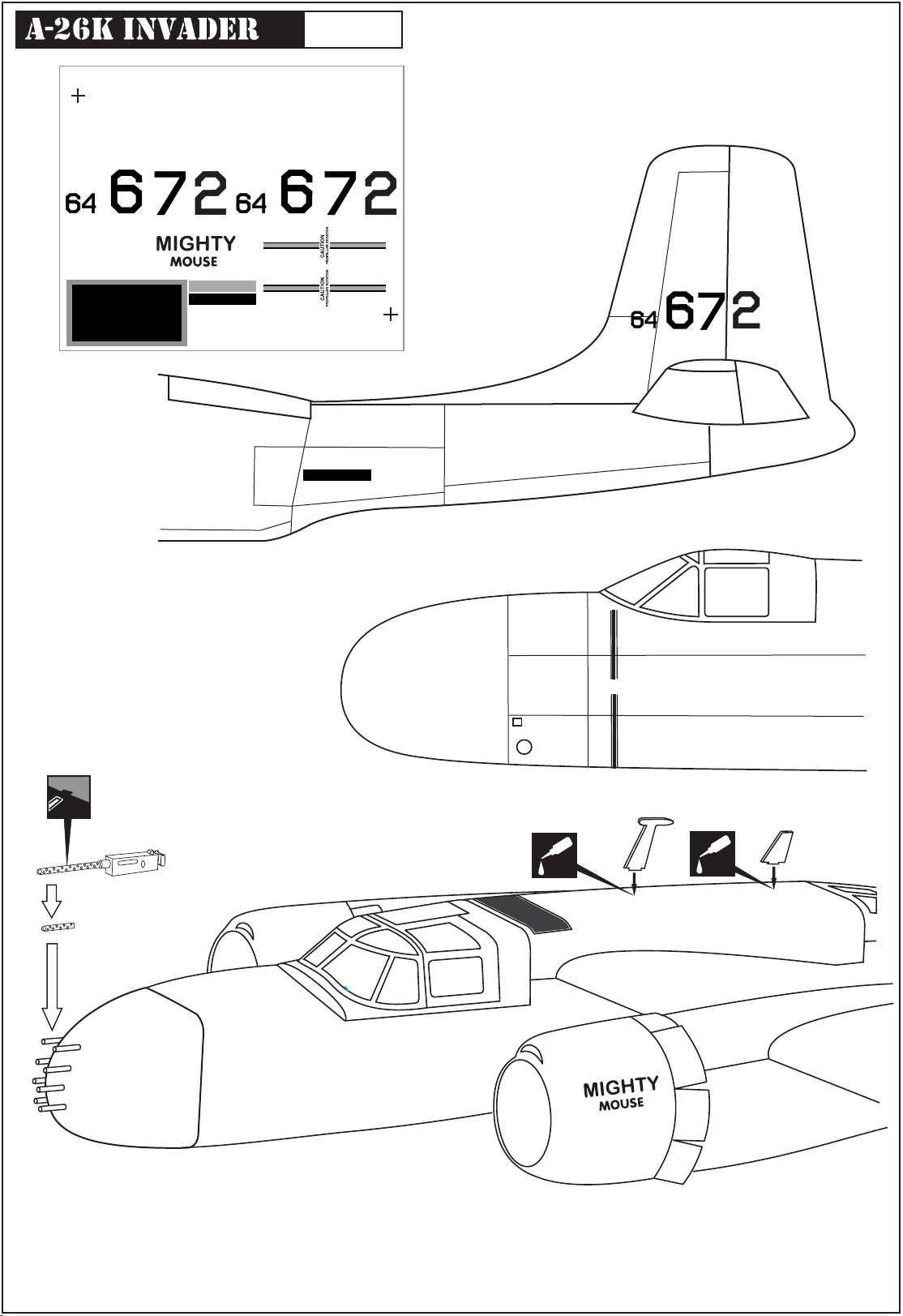
Decor
AF
T
A
FIRE EXTINGUISHER
FIRE EXTINGUISHER
NO STEPNO STEP
NO STEPNO STEP
T
AF
A26 - VIET-NAM WAR - DECAL SHEET .VQ MODEL
FIRE EXTINGUISHER
A
AF
T
A
CA
CAUTION
PROPELLER ROTATION
CA
IMPORTANT:
Please do not clean your model with pure alcohol, only use liquid soap with water or use glass cleaner
to clean on surface of your model to keep the colour not fade.
19
Page 20
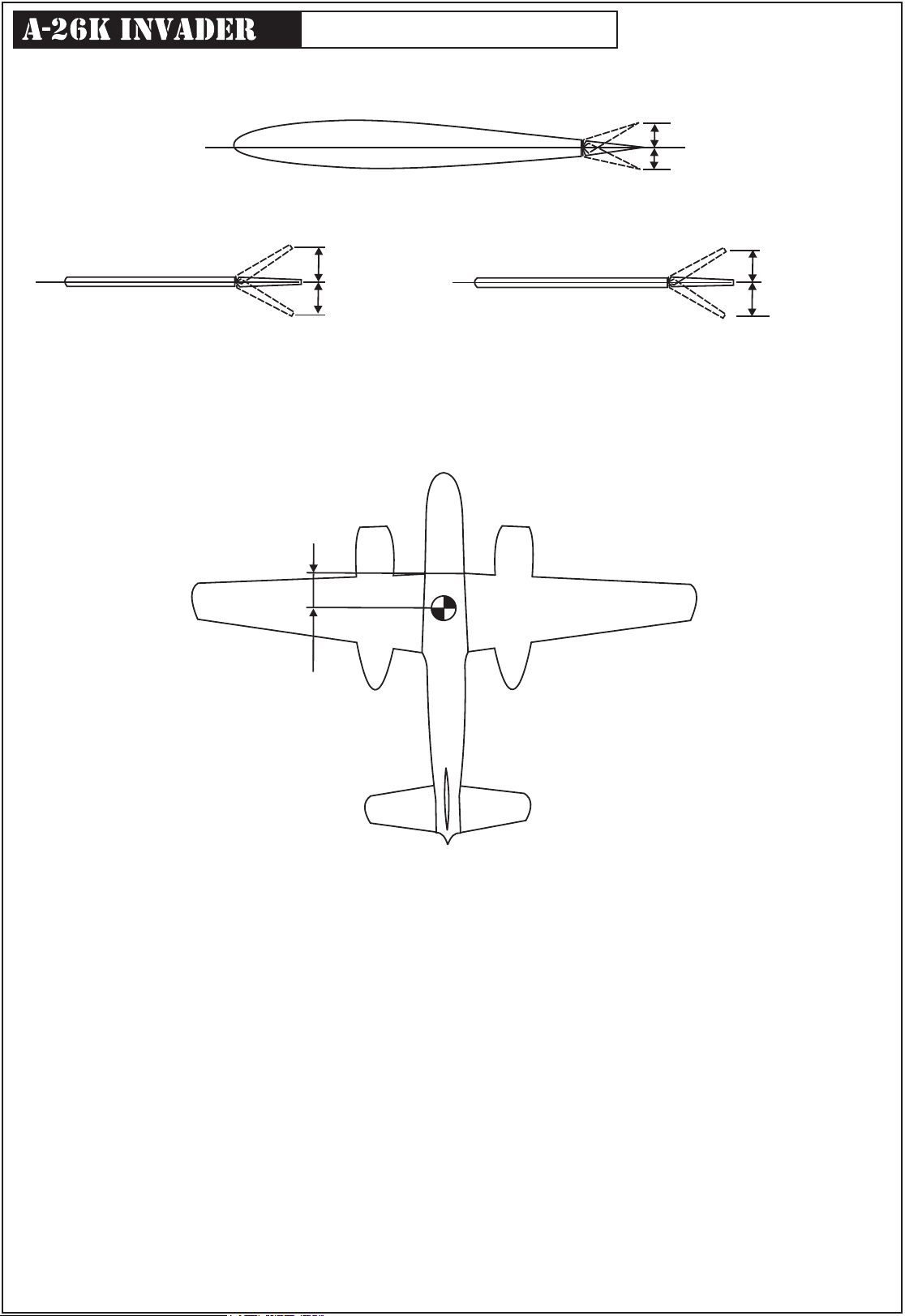
Control surface - Balance
AILERON
QUERRUDER
½ in (13mm)
½ in (13mm)
¾ in (20mm)
RUDDER
¾ in (20mm)
SEITENRUDER
Adjust the travel of the control surfaces to achieve the values stated in the diagrams.
These value will be suitable for average flight requirements. Adjust the values to suit your particular needs.
ELEVATOR
HÖHENRUDER
4.3 in. (110mm)
½ in (13mm)
½ in (13mm)
THE CENTER OF GRAVITY IS LOCATED 106 - 112mm BACK FROM THE
LEADING EDGE OF THE WING, AT THE FUSELAGE.
If the nose of the plane falls, the plane is heavy nose. To correct this, move the battery pack further back in the fuselage.
If the tail of plane falls, the plane is tail heavy. To correct this, move the battery forward or if this is not possible, stick weight onto the
firewall.
When balanced correctly, the airplane should level or slightly nose down when you lift it up with your fingers (or model airplane
balancer).
DO NOT try to fly an out-of-balance model !
20
 Loading...