

Page 1
ADI40 series
START UP GUIDE
Revision 1.01
20th January 2016
Page 2

Analogue<>Digital Interface User Manual
IMPORTANT SAFETY INSTRUCTIONS
This equipment is designed to comply with BSEN 61010-1
(Safety requirements for electrical equipment for
measurement, control, and laboratory use) – observe the
following precautions:
• Ensure that the supply voltage agrees with the rating
of the instrument printed on the back panel before
connecting the mains cord to the supply.
• This appliance must be earthed. Ensure that the
instrument is powered from a properly grounded
supply.
• High voltages can be generated if current flow to
inductive components is interrupted. Turn off the
output before connecting or
disconnecti ng any component.
• Keep the ventilation holes on the underneath and
sides free from obstruction.
• Do not operate or store under conditions where
condensation may occur or where conducting debris
may enter the case.
• There are no user serviceable parts inside the
instrument – do not attempt to open the instrument,
refer service to the manufacturer or his appointed
agent.
Note: Newtons4th Ltd. shall not be liable for any
consequential damages, losses, costs or expenses
arising from the use or misuse of this product
however caused.
i
Page 3

Analogue<>Digital Interface User Manual
DECLA RA TION OF CONFORM ITY
Manufacturer: Newtons4th Ltd.
Address: 1 Bede Island Road
Leicester
LE2 7EA
UK
We declare that the product:
Description: Analogue<>Digital Interface
Product name: ADI40
Conforms to the requirements of Co unci l Directives:
2014/30/EU relating to electromagnetic compatibility:
EN 61326-1:2013
2014/35/EU relating to the safety of laboratory
equipment:
EN 61010-2-30:2010
01/10/2015
Stuart Chappell
(Director Newtons4th Ltd.)
ii
Page 4

Analogue<>Digital Interface User Manual
WARRANTY
This product is guaranteed to be free from defects in
materials and workmansh ip for a period of 36 month s fro m
the date of purchase.
In the unlikely event of any problem within this guarantee
period, first contact Newtons4th Ltd. or your local
representative, to give a description of the problem. Please
have as much relevant information to hand as possible.
If the pr ob lem cann ot be resolved directly then you will be
given an RMA number and asked to return the unit. The
unit will be repaired or replaced at the sole discretion of
Newtons4th Ltd.
This guarantee is limited to the cost of the ADI40 it s elf a nd
does not extend to any consequential damage or losses
whatsoever including, but not limited to, any loss of
earnings arising from a failure of the produc t or software.
In the event of any problem with the instrument outside of
the guarantee period, Newtons4th Ltd. offers a full repair
and re-calibration service – contact your local
representative.
It is recommended that the ADI40 be re-calibrated
annually.
iii
Page 5

Analogue<>Digital Interface User Manual
ABOUT THIS MANUAL
The Analogue<>Digital Interface from Newtons4th Ltd
(ADI40) is a precision interface for use with the PPA45/55
range of power analysers.
This manual is concerned specifically with the ADI40 and
its use to measure and output DC voltages – a working
knowledge is assumed of the PPA instrument that it is
used with.
A detailed description of the PPA45/55 Power Analyser
may be found in the appropriate user manual.
Revision 1.01
This manual is copyright © 2015 Newtons4th Ltd. and all
rights are re served. No part may be copied or reprodu ced
in any form without prior written consent.
06 November 2018
iv
Page 6

Analogue<>Digital Interface User Manual
CONTENTS
1
ADI40 – an overview .......................................... 1-1
2 Getting started .................................................. 2-1
2.1 Unpacking .............................................................. 2-1
2.2 Initial s etup ............................................................ 2-1
3 Using the ADI40................................................. 3-1
3.1 Basic Operation ...................................................... 3-1
3.2 Example Application Overview .................................. 3-2
3.3 Initial S etup ........................................................... 3-3
3.4 Making Measurements ............................................. 3-3
3.5 Mapping Data to the Outputs .................................... 3-4
4 Communications Commands ................................ 4-1
5 Compensation.................................................... 5-1
5.1 Thermocouples ....................................................... 5-1
5.2 Standard Input Calibration ....................................... 5-2
5.3 Input C alibration P roc e dure ...................................... 5-3
6 Specification ...................................................... 6-1
v
Page 7

Analogue<>Digital Interface User Manual
APPENDICES
Appendix A Accessories
Appendix B ADI40 variant information
Appendix C Contact details
vi
Page 8

Analogue<>Digital Interface User Manual
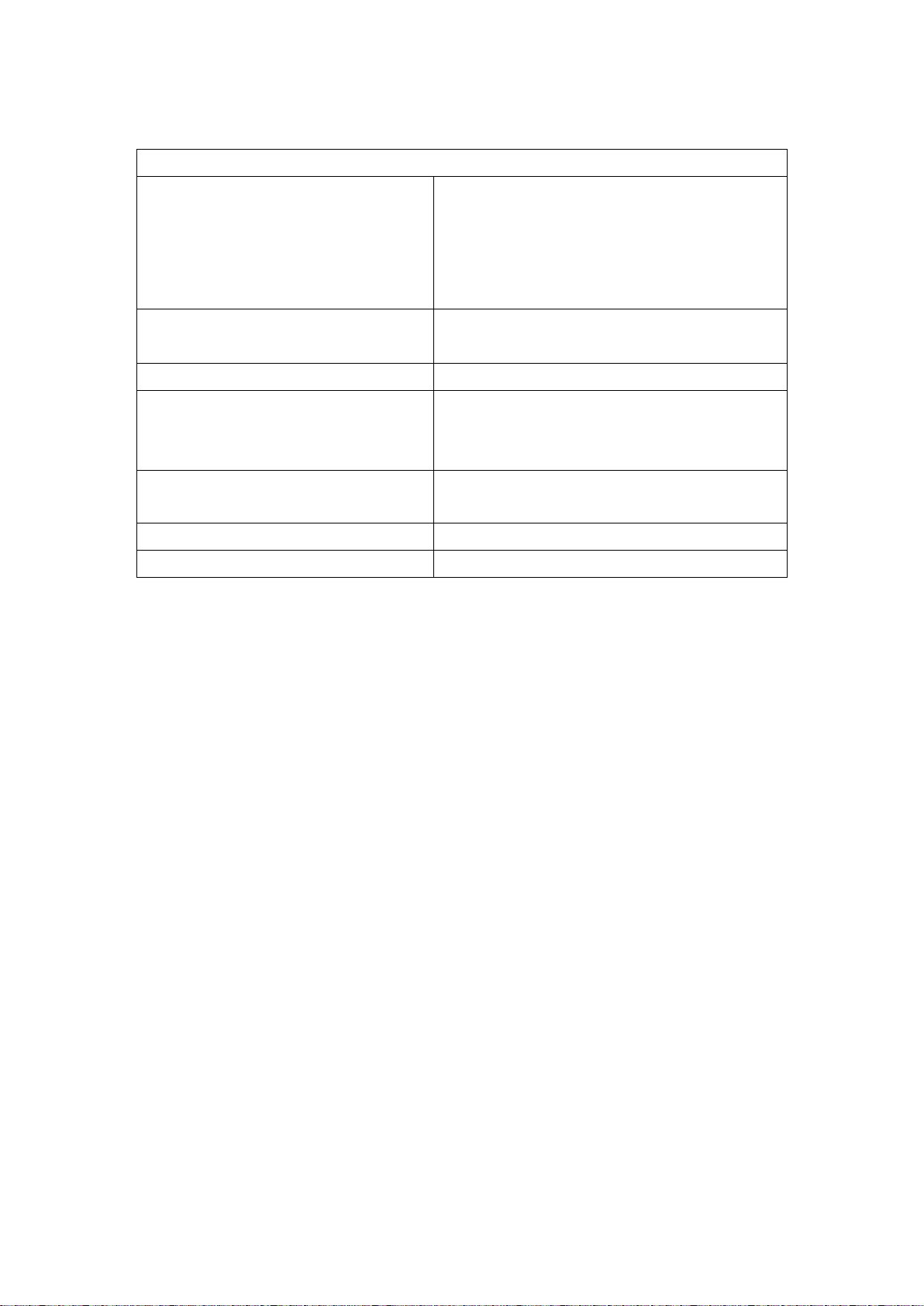
Model
+/- 10Vdc in put s
Thermocou p le inputs
ADI40
16
4
ADI40-8
12
8
ADI40-12 8 12
1 ADI40 – an overvie w
The ADI40 Analogue<>Digital Interface unit is a powerful
multi-channel measurement system for use in conjunction
with the PPA4500 and PPA5500 Power Analysers. It offers
a seamless interface between the Power Analyser,
Analogue Signals and Software.
The unit can also interface with chart recorders via 20 DC
output channels, which may be mapped to any of the
internally computed/logged measurements made by the
PPA. These outputs can produce DC voltages within the
range of +/-10V at 5mV intervals and have an output
impedance of 10 ohms.
Each unit has 20 input channels with the number of each
input type varying according to A DI40 variant, as shown in
the table below.
The inputs are diff erential w ith a range of +/-10VDC and
can be driven up to 20VDC without causing irreversible
damage to the internal circuitry. Each input’s impedance to
ground is 1MΩ.
The thermocouple inputs are differential with a range of
+/-20mV. The correct compensation can be applied for
both type J and K. An internal temperature sensor
provides cold junction compensation to within +/-0.4degC.
Model variants with more than 12 thermocouple channels
are available upon request, please contact customer
services at Newtons4th Ltd.
1-1
Page 9

Analogue<>Digital Interface User Manual
2 Getting started
The ADI40 is supplied with appropriate leads and
accessories for use with the PPA45/55 Precision Power
Analyser from Newtons4th Ltd. The ADI40 calibration can
be performed with any PPA45/55 and can then be used
with any other unit without recalibration – see the later
chapter on calibration.
2.1 Unpacking Inside the carton there should be the followi ng items:
One ADI40 unit
One appropriate mains lead
One 2mm slotted screwdriver
Eight 10 way 3.5mm straight plugs
ADI40 Start up Guide
There may also be a number of optional accessories if
these have been ordered with t he unit.
Having verified that the entire above list of contents is
present, it would be wise to verify that your ADI40
operates correctly and has not been damaged in transit.
2.2 Initial setup Site the ADI40 under the instrument that it will be used
with. Connect the ribbon cable from the extension port on
the back of the ADI40 to the extension port on the rear of
the PPA.
Verify that the voltage ratings on the rear panels of the
ADI40 and the instrument are appropriate for the supply,
2-1
Page 10

Analogue<>Digital Interface User Manual
and then connect the ma ins cords t o th e inle ts on the rear
panels and the supply outlet.
Switch on the ADI40 and the instrument. The POWER led
should illuminate a n d t h e A UX le d w il l f la s h, in d ic atin g th a t
the auxiliary cable is connected but communication has not
yet been es ta bli shed.
Press the AUX key on the instrument, ensure that
“master/slave” is disabled and then select “ADI40” from
the “auxiliary device” menu. Press the HOME key twice for
the change to take effect. The AUX led should stop flashing
and the OUT and IN leds will begin to flash sequentially.
If the led’s do not flash, then check that the extension port
cable has not been damaged and has been correctly fitted
between the instrument and the ADI40.
In the event of any problem with this procedure, please
contact cust omer ser vices at Newt ons4th Lt d. or your local
authorised representative: contact addresses and
telephone numbers are given in the appendix at the back
of this manual.
2-2
Page 11

Analogue<>Digital Interface User Manual
3 Using the ADI40
3.1 Basic Operation Continuous measurements are made by the ADI40 inputs
whenever it is connected to a PPA45/55 with the correct
AUX menu setup. Measurement data can be accessed in
the following ways:
- Using the ANALOG,channel? command to monitor the
inputs in CommView2
- Assigning inputs to MULTIL,1-60 and reading back
with MULTIL? or MULTIL,lines?, in CommV iew2
- Using the N4L PPALoG software to log and export
measurement data.
The ADI40 inputs can be used with a wide variety of
sensors and components such as Airflow rate sensors,
pressure sensors and DC fans.
The ADI40 outputs are also updated whenever it is
connected to a PPA45/55 with the correct AUX menu
setup. Outputs can be accessed in the followings ways:
- Using the ANALOG,channel,value command to
manually set the output voltage to a DC value
between +/ -10.
- Using the ADIMAP co mmand to map a PPA parameter
or ADI40 input back onto one of the outputs.
A detailed example of using the MULTIL and ADIMAP
commands are given in section 3.2.
3-1
Page 12
Analogue<>Digital Interface User Manual
When not in use, it is recommended that short linking
wires be screwed between each + and – thermocouple
terminal pair. This eliminates noise pickup and allows the
internal temperature of the ADI40 to be monitored.
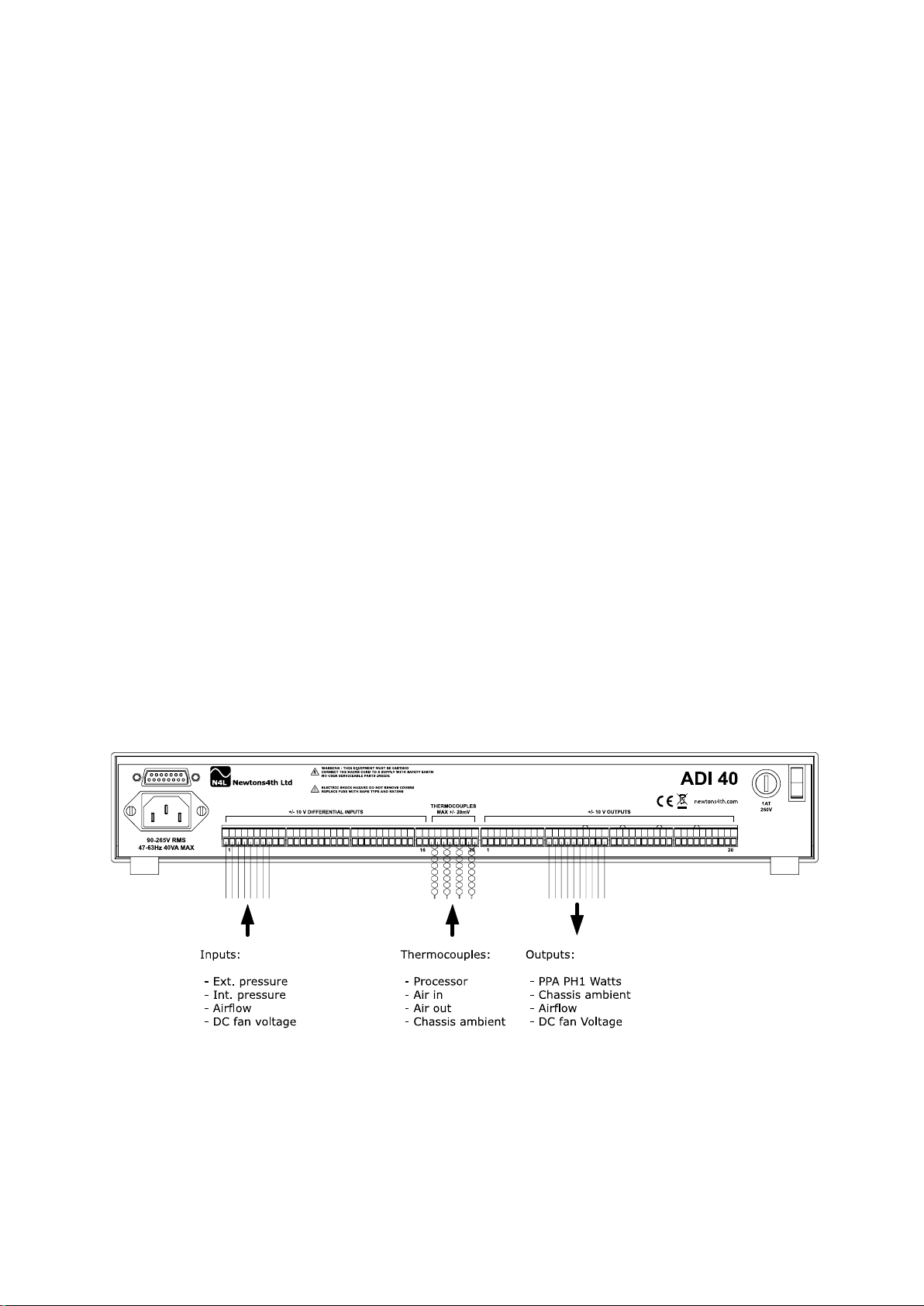
3.2 Example Application Overview This e x a mp le w il l demonstrate how the ADI40 can be used
to monitor the performance of a desktop PC. Internal
chassis pressure, external atmospheric pressure, airflow
through the chassis and DC fan voltage are mon itored with
the +/-10V inputs. The thermocouple inputs are used to
measure, main CPU temperature, air temperatures on and
off the heat sink and chassis ambient temperature. An
example of how this would be wired to the ADI is shown
below. The PPA45/55 Phase 1 voltage and current inputs
are connected to the PC mains inlet to monitor its power
consumption.
3-2
Page 13

Analogue<>Digital Interface User Manual
3.3 Initial Setup First, confirm that all sensor wires and thermocouples are
of sufficient length to reach the DUT comfortably. If
possible, avo id runn ing thermocouples c lose to very noisy
electri cal equipment.
Unplug the terminal blocks to be used and secure sensors
and thermocouples to their respective terminals, using a
2mm flathead screwdriver.
The ADI40 and PPA45/55 should now be set up as
described in section 2.2. Once powered up, connect the
terminal blocks back into the ADI40. The thermocouples
being used must all be of either t ype J or K, a mixt ure of
the two is not supported. The appropriate thermocouple
type can be chosen in the AUX menu.
The outputs can then also be connected to a Chart
Recorder, using appropriate gauge and length of wire.
Disconnecting the terminal blocks before securing wires in
place is advisable to ensure good contact is made.
3.4 Making Measurements A PC running the N4L Commview2 or PPALoG software is
required to observe and/or record measurements made by
the ADI40. For this example, Commview2 will be used to
observe all measure ments made and output some o f them
to the Chart Recorder.
First, confirm that all inputs are reading within the
expected range by using the ANALOG? command.
ANALOG,1?;ANALOG,2?;.....
3-3
Page 14

Analogue<>Digital Interface User Manual
If the measurements confirm that the ADI40 has been
connected correctly, the inputs can next be assigned to
Multilog channels with the MULTIL command.
The MULTIL command is used to assign up to 60 data
values or parameters to be read back in a single multi
string reply. In this example we wish to read back the
following:
- The various sensors and DC fan on ADI inputs 1 – 4
- The various PC temperatures on ADI inputs 17 - 20
If we assign these inputs using MULTIL, they can then be
read back as a single multi string response using MULTIL?:
MULTIL, 0 (clear anything previousl y assig ned )
MULTIL, 1, 6, 1
The comman ds sh own abo ve clea rs an y old Mult ilog setup
and then assigns ADI input 1 (6,1) to MULTIL channel 1
(MULTIL,1,). The same is then done for the rest of the ADI
inputs:
MULTIL,2,6,2; MULTIL,3,6,3;... MULTIL,8,6,20
Sending the MULTIL? command will now return a string
containing the last set of readings made on channels 1-4
and 17-20. The changes in voltages and temperatures can
now be monitored.
3.5 Mapping Data to the Outputs To send some of this data back to the ADI40 outputs, the
ADIMAP command is u sed. Any da ta value st ored in one of
3-4
Page 15

Analogue<>Digital Interface User Manual
the MULTIL channels can be offset, scaled and then sent to
an ADI40 output.
In this example, we want to map PPA PH1 Watts, chassis
ambient temperature, airflow sensor output and DC fan
voltage to the ADI40 outputs. Assuming the inputs are
assigned to the same Multilog channels as given in the
previous sect ion, we can map the airflow sensor (input 3)
to output 8 by sending:
ADIMAP,8 ,3 ,0 ,0.8
This a ss igns Multilog channel 3 to ADI output 8, with 0
offset and scaled by 0.8. As a further example, if PH1
Watts is assigned to Multilog,9 with:
MULTIL,9 ,1 ,2
Then Watts (multiplied by 0.5) can be mapped to output 6
with the command:
ADIMAP,6 ,9 ,0 ,0.5
Providing the ADI40 is correctly setup, the outputs
selected will begin to map their assigned Multilog channel.
The MULTIL? and ANALOG? commands can still be used
after mapping inputs to outputs, witho ut iss ue.
N4L Software is available as a free download from our
website
www.newtons4th.com (support section).
3-5
Page 16

Analogue<>Digital Interface User Manual
ANALOG
ANALOG
Function:
Interface with ADI40
Description:
Write to individual ADI40 outputs
Format:
ANALOG,channel,value
Arguments:
Channel:
-10.00 to +10.00
Reply:
None
Example:
ANALOG,5,-3.14
Notes:
Up to 9 outputs can be written to with one
by separating each
4 Communications Commands
1-20
Value:
CommView transfer,
instance with a “;”.
4-1
Page 17

Analogue<>Digital Interface User Manual
ANALOG?
ANALOG?
Function:
Interface with ADI40
Description:
Read from individual ADI40 inputs
Format:
ANALOG,channel?
Arguments:
Channel:
1-20
Reply:
ASCII characters in scientific format:
17- 20 in ˚C
Example:
ANALOG,12?
Notes:
Up to 9 inputs can be read back at once
with this command by separating each
1 - 16 in Volts
instance with a “;”.
4-2
Page 18

Analogue<>Digital Interface User Manual
MULTIL
MULTIL
Function:
Selects data for multi string reply
Description:
Selects data values across phases and
functions that can be read in a single
string.
Format:
MULTILOG,index,type,function
Arguments:
index:
1-60 assign to value
Reply:
none
Example:
MULTIL,0
3 data values returned for inputs 1 - 3
0 clear all
1-60 select data 1-20
type:
1-3 phase 1-3
4 sum
5 neutral
6 adi40
function:
MULTIL,1,6,1
MULTIL,2,6,2
MULTIL,3,6,3
MULTIL?
4-3
Page 19

Analogue<>Digital Interface User Manual
MULTIL?
MULTIL?
Function:
Reads multi string reply
Description:
Waits for data to be available then returns
Format:
MULTILOG?
Arguments:
Lines:
Reply:
Up to 60 data values as selected by the
Up to 60 data values as selected by the
Example:
MULTIL,0
Notes:
The MULTILOG,lines? command will reply
selected results.
Or:
MULTILOG,lines?
Integer
MULTILOG command in a single reply
string
OR
MULTILOG command in a single reply
string, replying “lines” times.
MULTIL,1,6,2
MULTIL,2,6,2
MULTIL,3,6,3
MULTIL?
3 data values returned
MUTLIL,5?
Rep lies 5 times, each conta ining 3 data
values
each time a new data point is available.
4-4
Page 20

Analogue<>Digital Interface User Manual
ADIMAP
ADIMAP
Function:
Map multilog parameters to outputs
Description:
Applies offset and scaling to a multilog
value and maps value to chosen ADI
Format:
ADIMAP,output,multilog,offset,scale
Arguments:
output:
Reply:
None
Example:
MULTIL,0
Notes:
Offset is subtracted from multilog value,
output
1-20
multilog:
1-64
offset:
Float
scale:
Float
MULTIL,2,1,1 (PH1 Frequ e n cy)
ADIMAP,1,2,0.2,0.5
Output 1 = 0.5 * (PH1 frequency – 0.2)
then scale is applied within the limits of
+/- 10
4-5
Page 21

Analogue<>Digital Interface User Manual
5 Compensation
5.1 Thermocouples The thermocouple inputs can be zeroed to remov e small
variations in measurem ents between channels. The
following sequence is carried out during the produc ti o n
stage, but the user may wish to perform it again. To check
the thermocouple inputs for dr ift; follow steps 1 to 3
below, use the ANALOG command to check all channels
are reading the same room temperature and complete
steps 4 to 6 if they vary by more than +/-0.2˚C.
1. Set-up you're ADI40 as de scribed in sec tion 2.2.
2. Screw small shorting wires between the + and –
terminals of each thermocouple channel, as shown
below:
5-1
Page 22

Analogue<>Digital Interface User Manual
3. Plug the terminal block into the corresponding socket,
ensuring it is full y loc k ed in plac e.
4. In the AUX display, select ‘manual zero’ from the ADI
adjustment menu.
5. With the cursor, highlight the ‘press ENTER here to
execute’ text and press ENTER.
6. Verify that all thermocouple channels have been
zeroed correctly.
If this process does not remove the offset or makes it
worse, check thermocouples for damage or bad contact.
In the event of any problem with this procedure, please
contact cust omer ser vices at Newt ons4th Lt d. or your local
authorised representative: contact addresses and
telephone numbers are given in the appendix at the back
of this manual.
5.2 Standard Input Calibration Calibrating the ADI40 inputs requires a PPA45/55 and a
precision reference voltage of +8V and -8V. The ADI40
uses the reference voltage to produ ce a t able of ca l ibr a tion
factors, which are stored in internal flash memory. All
inputs must be calibrated together at the same time.
The calibration instructions given here will use the ADI40
reference voltage calibration fixture available from
Newtons4th Ltd, to demonstrate the process.
5-2
Page 23
Analogue<>Digital Interface User Manual
For further information about calibrating the ADI40 please
contact cust omer ser vices at Newt ons4th Lt d. or your local
authorised representative: contact addresses and
telephone numbers are given in the appendix at the back
of this manual.
5.3 Input Cali b ra tion Proced ure
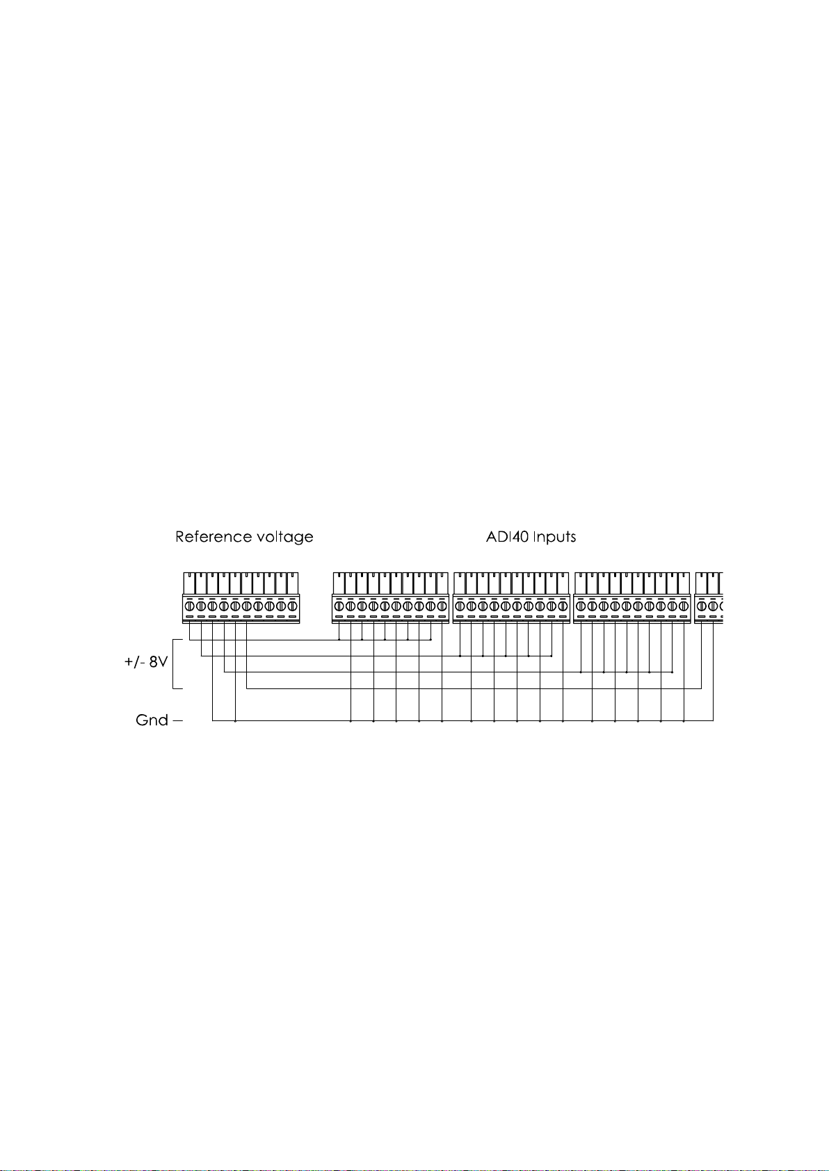
1. Set-up your ADI40 as described in section 2.2.
2. Wire all ADI40 inputs to the calibration reference
voltage, as shown in the diagram below:
3. Verify the output is +8.000V, using a precision DMM
(Digital Multimeter).
4. Select +8V in the ADI adjustment menu. With the
cursor, highlight the ‘press ENTER here to execute’
text and press ENTER.
5. Verify that the IN and OUT leds begin to pulse
sequentially at a faster rate, for about 2 seconds. If
5-3
Page 24

Analogue<>Digital Interface User Manual
the leds flash together, the calibration did not occur
as one or more of the inputs were out of range.
6. Verify the output is -8.000V, using a precision DMM
(Digital Multimeter).
7. Select -8V in the ADI adjustment menu. With the
cursor, highlight the ‘press ENTER here to execute’
text and press ENTER.
8. Verify that the IN and OUT leds begin to pulse
sequentially at a faster rate, for about 2 seconds. If
the leds flash together, the calibration did not occur
as one or more of the inputs were out of range.
9. Verify input calibration was successful by using
CommVi ew2 and t he r eferen ce voltage.
In the event of any problem with this procedure, please
contact cust omer ser vices at Newt ons4th Lt d. or your local
authorised representative: contact addresses and
telephone numbers are given in the appendix at the back
of this manual.
5-4
Page 25
Analogue<>Digital Interface User Manual
System
Standard Inputs
Basic Accuracy
0.1% Full Scale
Voltage Range
Bip olar + /- 10V
Maximum Input Voltage
+/- 30V
Maximu m Common M ode
Voltage
- 1V ~ +14V
Thermocouple Inputs
Voltage Range
Bip olar + /- 20mV
Maximum Input Voltage
Bip olar + /- 50mV
All Inputs
Input Impedance
1MΩ
Update Rate
10ms
Resolution
12 bit
Outputs
No. Of Outputs (DC)
20
Voltage Range
Bip olar + /- 10V
Slew Rate
0.1V/µS
Maximum Source Current
50mA
Output Impedance
10Ω
Accuracy
0.1% Full Scale
Resolution
12 bit
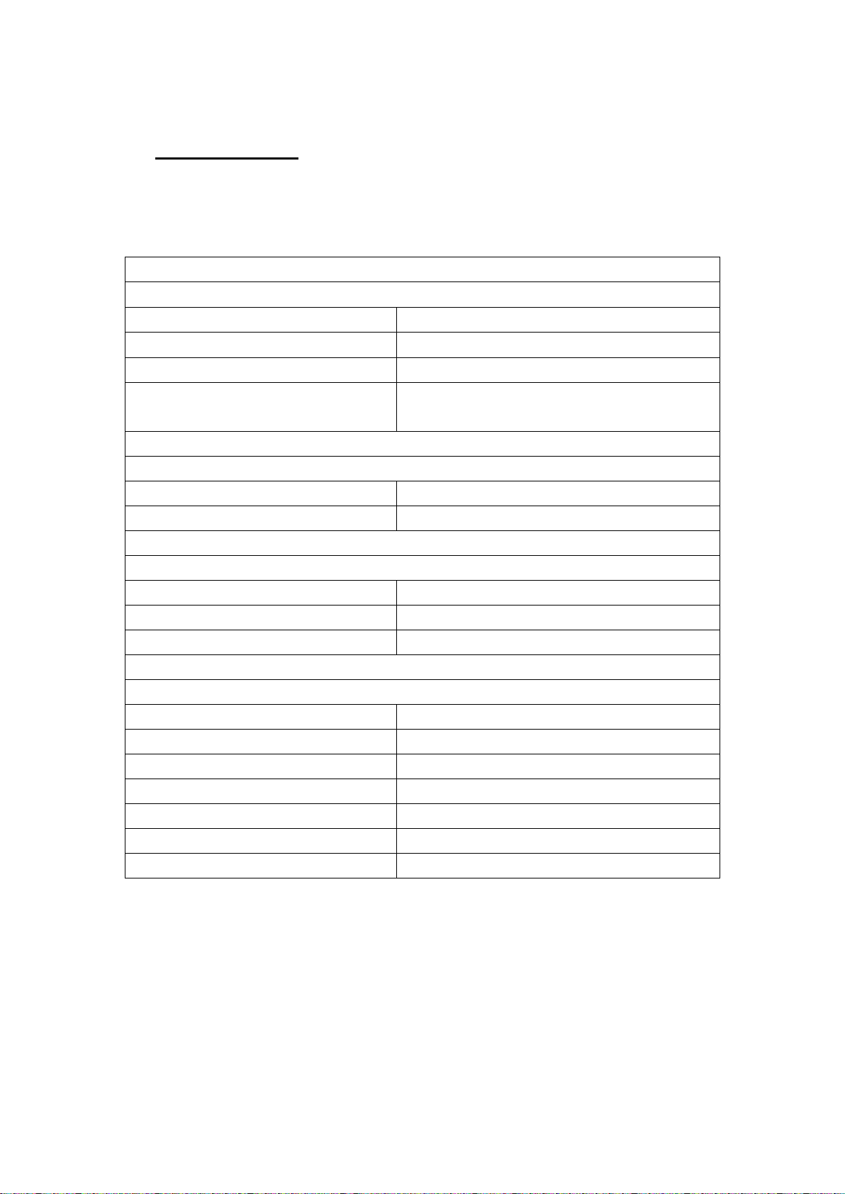
6 Specification
All specifications are quoted for the ADI40 only.
6-1
Page 26
Analogue<>Digital Interface User Manual
General
Operating Conditions
23˚C ± 5˚C Ambient
Condensing Relative Humidity.
Temperatu re coeffici en t
±0.01% per ˚C of reading at
5-18˚C and 28-40˚C
Connectors
40 x 3.5mm screw terminal
Power Requirements
universal input
40VA max.
Size
H: 62.4mm, W: 395mm, L:
280 mm approx
Weight
2kg approx
Warranty
3 Years
Temperatu re (or air intake
temperat ur e when rack
mounted), 20-90% Non-
90-265V rms, 47-63Hz
6-2
Page 27
Analogue<>Digital Interface User Manual
500-365
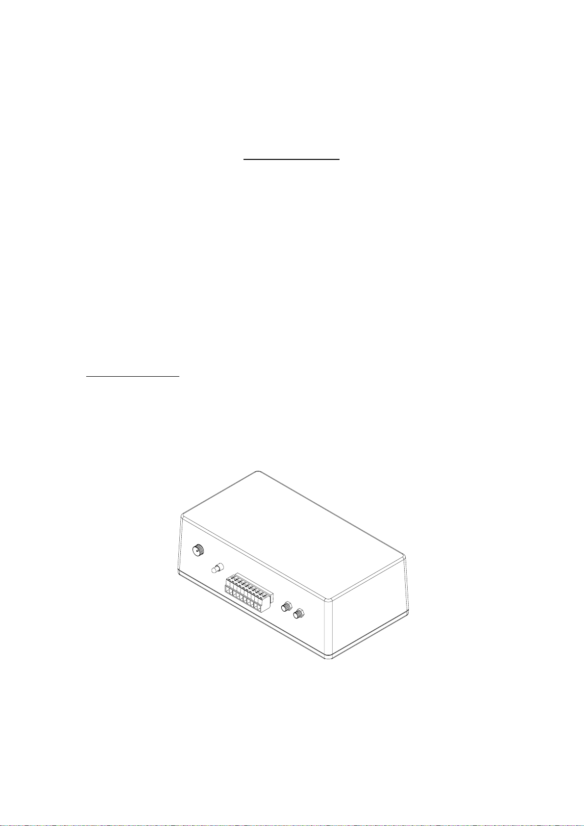
ADI40 calibration kit
Appendix A – Accessories
Calibration kit
The ADI40 is calibrated with a voltage reference unit and a
PP45/55A P ower A naly ser. Calibration values are sto red in
the non-volatile FLASH memory of the instrument.
The calibration unit includes the necessary calibration
cable assembly.
A 2.1mm DC power supply within the range of 9 – 18V is
required to power the unit.
Part numbers
A-1
Page 28
Analogue<>Digital Interface User Manual
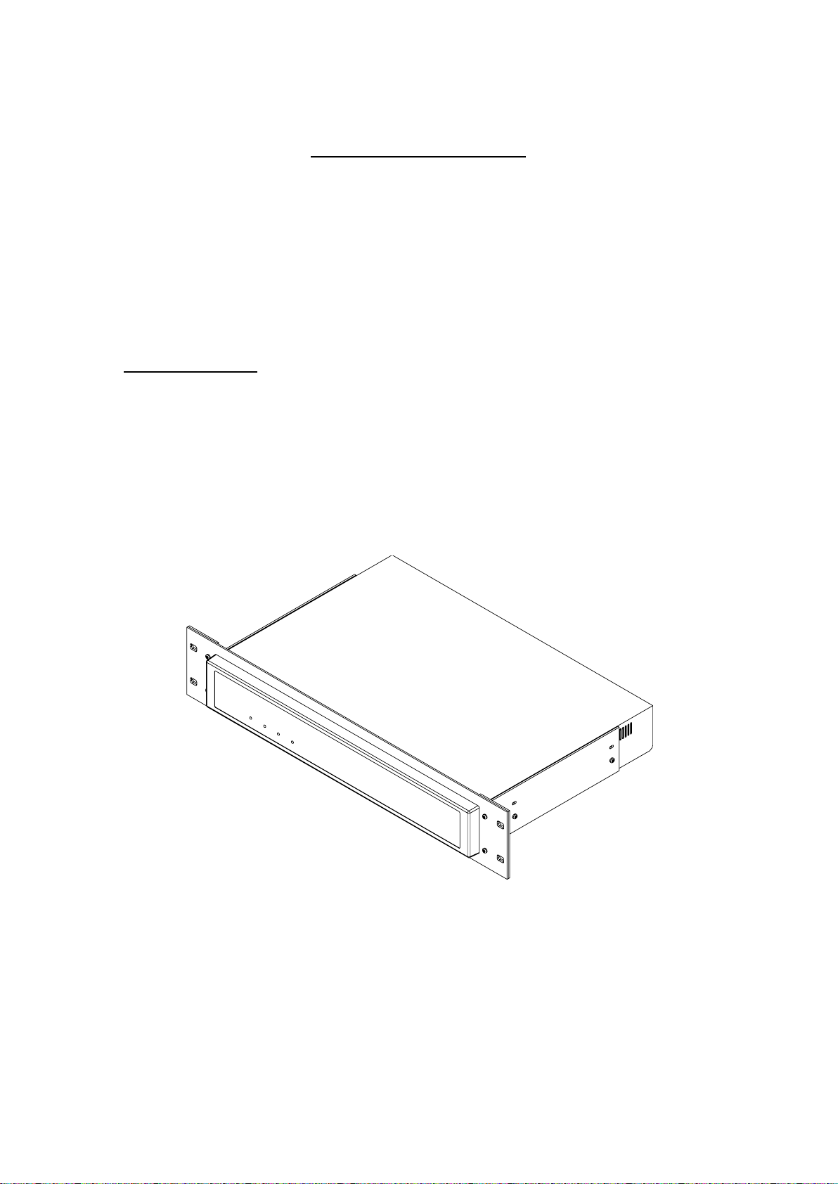
515-253
ADI40 19” rack mounting kit
19” rack mounting kit
The ADI40 can be integrated into 19” rack systems using a
2U custom rack mounting kit.
The kit consists of one front panel, two universal brackets
and eight black M3 x 10mm pan head bolts.
Part numbers
A-2
Page 29
Analogue<>Digital Interface User Manual
Appendix B – ADI40 variant information
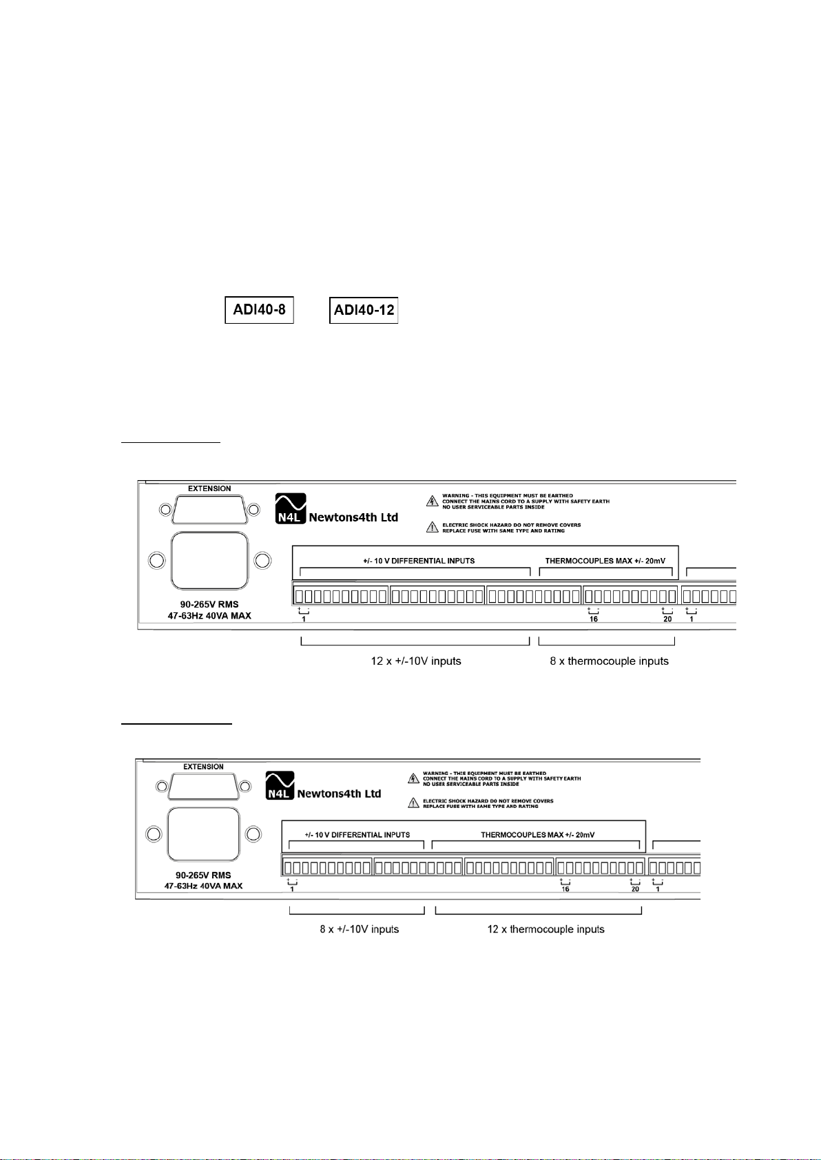
There are currently 3 ADI40 variants available: the
standard 4 thermocouples, 8 thermocouples and 12
thermocouples.
If you do not have the standard unit, there will be an
additional or model overlay located under
the power switch on the rear of the unit.
The inputs types are given below for each ADI40 model.
ADI40 – 8
ADI40 – 12
B-1
Page 30

Analogue<>Digital Interface User Manual
Appendix C – C ontact details
Plea se d irec t a ll que rie s or comm ents regarding the ADI40
instrument or manual to:
Newtons4th Ltd.
1 Bede Island Road
Leicester
LE2 7EA
United King dom
Tel: (0116) 230 1066 international +44 116 230 1066
Fax: (0116) 230 1061 international +44 116 230 1061
Web site: www.newtons4th.com
At Newtons4th Ltd. we have a policy of continuous product
improvement and are always keen to hear comments,
whether favourable or unfavourable, from users of our
products
C-1
 Loading...