


1-741

1-742
1-743
2001 CARNEGIE AVE, SANTA ANA CA 92705
(949) 417-5207
WWW.NEWPORTBRASS.COM
INSTALLATION INSTRUCTIONS
1/2” THERMOSTATIC VALVE AND TRIM
Valve Model No's: 1-741, 1-742, 1-743, 1-744
1-744
1-741

General Characteristics
In case of instantaneous heaters, hot water flow has to at least meet flow required by heater
and maintain burning. (Specified by heater manufacturer)
Operating Specifications
Hot water supply temperature:
Maximum: 185°F (85°C).
Note 1: Maximum temperature through this valve is limited by that of the hot water supply
(up to a maximum of 120°F when accurately calibrated).
Note 2: Minimum difference between hot and mixed temperature is 18°F (10°C).
Cold water supply temperature:
Minimum: 41°F (5°C)
Operating Pressure:
Maximum: 80 PSI
Minimum: 20 PSI
Operating pressure (on hot and cold line) should be kept as balanced as possible in order to
assure maximum efficiency.
When the pressure is greater than 80 PSI, a pressure reducer is required to be fitted
before valve.
Technical Data
The temperature control knob is graduated from 75°F to 120°F with auto stop at 100° to
avoid scalding.
Plumbing Recommendations
• An independent water supply for both hot and cold is required. Do not pipe off ring main.
• Large runs of pipe work will cause frictional loss of pressure.
• The recommended main water supply piping to valve shall be 1/2” minimum
• If more than one valve is installed, the recommended main water supply piping to valve shall
be 3/4” minimum, reducing to 1/2” within 24” of each valve.
(Ensure adequate supply from both hot and cold water can be maintained.)
Water By-Laws
The mixing valve should be installed in compliance with the water by-laws. For further details
refer to the latest copy of by-laws guide or your local water authority.
NWP-1-742
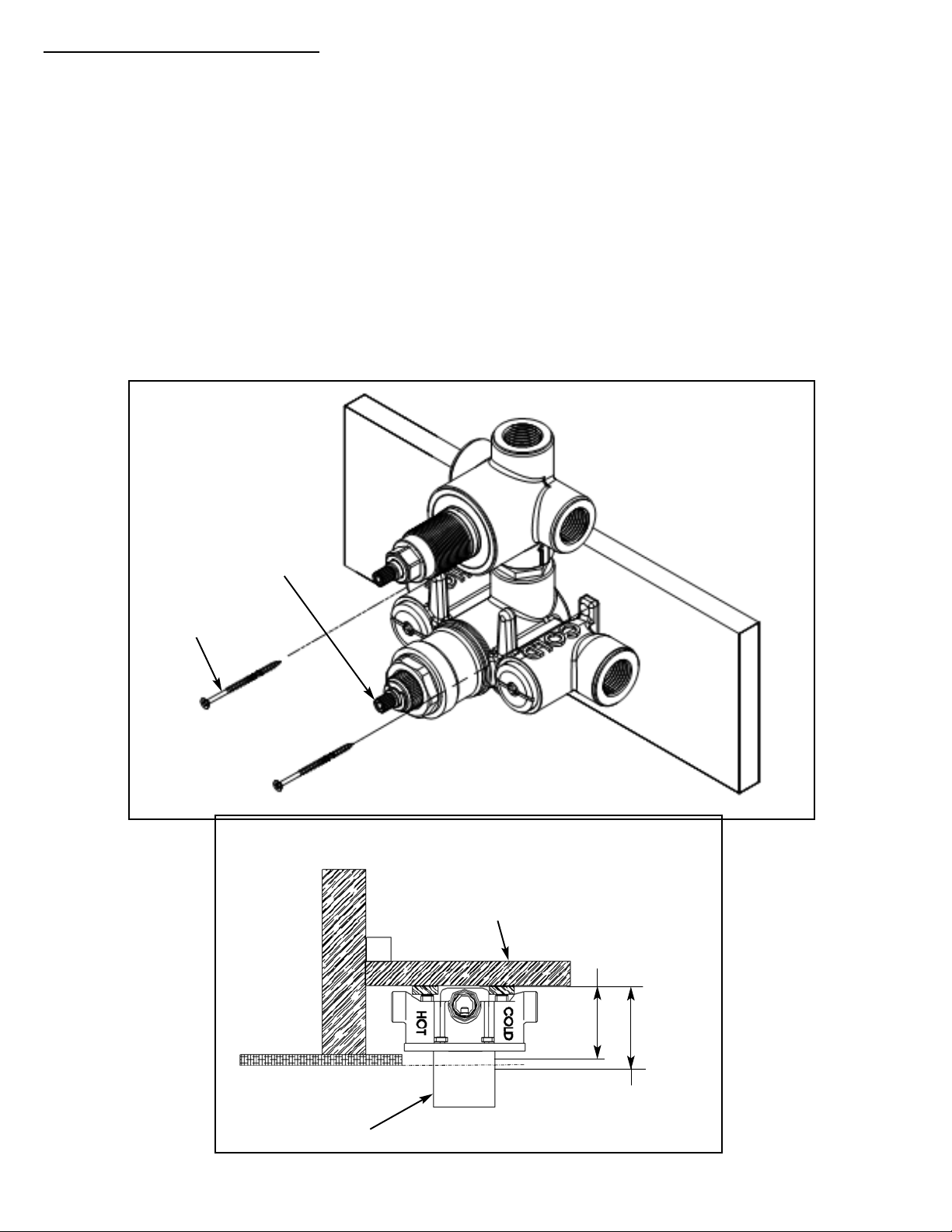
I. Rough in Valve Installation
Note: Use plumbers tape or equivalent to seal all threaded port joints. This valve is design to fit in
a 2" X 4" stud wall (or thicker) installation. Use stem extension kit #1-384 (sold seperately) if valve
installed is too far away from the finished wall.
1. Do not remove mud cover from valve before locating mounting surface depth in the wall.
2. Do not turn the cartridge stem - temperature settings are pre-calibrated at the factory.
3.
Mount valve to cross support using screws (not included). Valve shall be perpendicular and fixed
firmly to cross support to achieve proper trim attachment.(See Fig 1).
4.
Place the cross support with valve between wall studs. The min./max. valve depth and vertical
height desired within tub/shower enclosure determines the exact cross support placement.
Attach cross support to wall studs.(See Fig 2).
5.
Ensure opening in finished wall comes in contact with the mudcover to ensure seal with
Thermo Wall Plate shown in Fig. 4. (See TEMPLATE FOR FINISHED WALL OPENING in Fig 9).
Fig. 1
Cartridge stem
DO NOT TURN
2-3/8”
Min depth
3-1/8”
Max depth
Finished wall
Mud cover
Wall stud
Cross support
Fig. 2
NWP-1-742
Screws
(Not included)
 Loading...