


INSTALLATION
DOCUMENTS
INSTALLATION INSTRUCTIONS FOR PRESSURE BALANCINGVALVES
Newport Brass Offers Two Pressure Balance Shower Valves.
This Document Includes the Installation Instructions for Both Models.
1-594Tempress Pressure Balance ShowerValve (Page 2 - 5)
1-684 Newport Brass Pressure Balance ShowerValve (Page 6 -9)
1-594 |
1-684 |
w w w. n e w p o r t b r a s s . c o m
Newport Brass • 2001 Carnegie, Santa Ana CA 92705 • t: 949.417.5207 f: 949.417.5208 page 1 of 10
INSTALLATION INSTRUCTIONS
Tempress Pressure BalancingValve
Valve Body No.1-594
as used with Shower Fittings
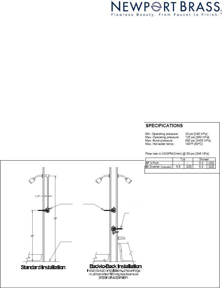
Note: This valve is designed to fit in a 2" X 4" stud wall (or thicker) installation. Use stem extension kit #1-384 (sold seperately) if valve installed is too far away from the finished wall.
Description
This valve is precision engineered to provide satisfactory performance provided it is installed and operated in accordance with our recommendations contained in these instructions.In order to fully enjoy the comfort, safety and the reliability of this valve,be certain to familiarize yourself with these instructions.
Operation
The pressure balancing cartridge contained in this valve compensates for pressure fluctuations in the water supply system through a diaphragm-connected pressure balancing mechanism.The outlet temperature will change by no more than a mere ±2°F (1°C) with a 50% drop in either the hot or cold water pressure.
Even if the coldwater pressure fails completely,the anti-scald design will reduce the flow rate to a safe level ensuring reliable protection against scalding.The built-in check valves prevent cross flow between the hot and cold supplies.
Illustration 1
 1-594
1-594
1-595 Balance
PressureValve w/ Diverter
Floor Line
|
|
|
|
|
|
|
|
Back to Back Installation |
|
Standard Installation |
|
|
|
|
|
|
In back to back installations,one cartridge |
||
|
|
|||
|
|
must be rotated 180 degrees to ensure |
||
|
|
|
proper valve operation |
|
|
|
|
|
|
NWP-1-594 |
06/13/18 |
Before you begin
Make sure valve is securely fastened to studs.Be sure to remove trim items,handles,escutcheons and plates before installation.Wrap carefully and store until finished wall is completed.
Install the valve by positioning the 1/2” shower outlet in the up position.Finished wall must be within dimensions shown on the chart below.
On tiled wall surfaces,grouting must be either flush or raised for proper sealing of the cover plate. IMPORTANT:It is not necessary to remove the cartridge from the valve during NORMAL soldering operations
using propane-butane gas.DO NOT USE OXYGEN-ACETYLENE. When soldering CxC connections,do not solder within 4” of valve port.Open the stop valves when soldering inlets.
To test pipe joints,pressurize both hot and cold inlets.
InstallingTrim
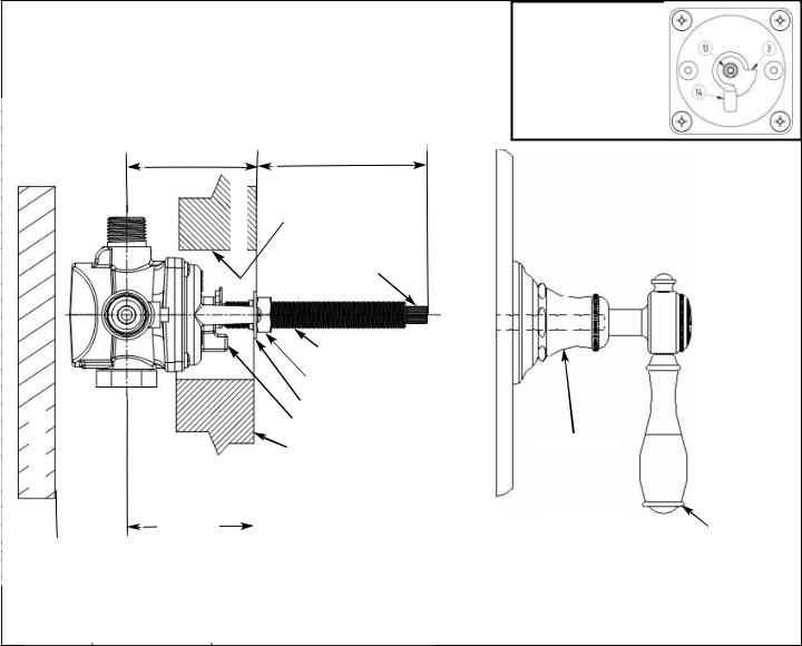
Place cover plate on valve stem and slide into position.Install escutcheon/bonnet trim and mark the all-thread nipple, (Item 1) were excess needs to be trimmed.
Remove escutcheon/bonnet trim and cut all-thread nipple 1/16” less than indicated mark to prevent exposure of nipple threads.NOTE:Do not cut stem,(Item 6),or all-thread nipple until finished wall is complete and a dimension check of handle and escutcheons/bonnet trim is done.(Stem is grooved at ½” intervals) Cut stem at least ½” past the end of the cut all-thread nipple.Final stem length may vary based on individual handle base insertion.Reinstall escutcheon/bonnet trim and handle.Secure handle into place by tightening the handle setscrew.(Ref.Illustrations 2 & 3)Turn on water supply to check for leaks.
Illustration 2
|
|
|
|
|
|
|
|
|
|
|
|
|||||||
|
|
|
|
|
|
|
|
|
|
3-3/4” |
||||||||
|
3-1/8” |
|
|
|
|
|
|
|||||||||||
|
|
|
stud |
|
|
|
|
|
|
|
|
|
|
|
|
|
|
|
|
|
|
|
|
|
|
|
|
|
|
|
|
|
|
|
|
||
|
|
|
4” hole for |
|
|
|
|
|
|
|
||||||||
|
|
|
of |
|
|
|
|
|
|
|||||||||
|
|
|
Face |
valve |
|
|
|
|
|
|
||||||||
|
|
|
|
|
|
|
|
|
|
|
|
|
|
|
|
|
||
|
|
|
|
|
|
|
|
|
|
|
|
|
|
|
|
|
||
|
|
|
|
|
|
|
|
|
|
|
|
|
|
|
|
|
|
|
|
|
|
|
|
|
|
|
Broach stem |
||||||||||
|
|
|
|
|
|
|
|
|
|
|
|
|
|
|
|
|
|
|
|
|
|
|
|
|
|
|
|
|
|
All thread nipple |
|||||||
|
|
|
|
|
|
|
|
|
|
|
|
|
|
|||||
|
|
|
|
|
|
|
|
|
Locking nut |
|||||||||
|
|
|
|
|
|
|
|
|
|
|
|
|
|
|
|
|
|
|
of stud |
|
|
|
|
|
Retaining plate |
||||||||||||
|
|
|
|
|
|
|
|
|
|
|
||||||||
|
|
|
|
Stop block |
||||||||||||||
|
|
|
|
|
|
|
||||||||||||
|
|
|
Face of FinishedWall |
|||||||||||||||
Face |
|
|
|
|
|
|
|
|
|
|
|
|
|
|
|
|
||
|
|
|
|
|
|
|
|
|
|
|
|
|
|
|
|
|||
3-1/4”  1-3/8” to
MIN 3-7/8”
Ensure that the stop ring (3) is correctly installed as follows:
-Rotate the cartridge stem (13) fully clockwise.
-Position the stop ring on the stem such that it rests
against the stop post (14). The stop ring must be correctly installed prior to finish trim
installation.
Escutcheon
 Cover plate
Handle
NOTE:Dimensions shown are from the inlet ports to the finished wall.
NWP-1-594 |
06/13/18 |
 Loading...