

Newport iServer MicroServer, iTHX-M Owner's Manual
http://www.newportUS.com/iServer
®
NEWPORT
Electronics,Inc.
Temperature +
Humidity
Operator’s Manual

Counters
Frequency Meters
PID Controllers
Clock/Timers
Printers
Process Meters
On/Off
Controllers
Recorders
Relative
Humidity
Transmitters
Thermocouples
Thermistors
Wire
Rate Meters
Timers
Totalizers
Strain Gauge
Meters
Voltmeters
Multimeters
Soldering Iron
Testers
pH pens
pH Controllers
pH Electrodes
RTDs
Thermowells
Flow Sensors
For Immediate Assistance
In the U.S.A. and Canada: 1-800-NEWPORT
®
In Mexico: (95) 800-NEWPORT
SM
Or call your local NEWPORT Office.
Internet e-mail
info@newportUS.com
Additional products from
NEWPORTnetSMOn-Line Service
www.newportUS.com
®
NEWPORT
Electronics,Inc.
It is the policy of NEWPORT to comply with all worldwide safety and EMC/EMI regulations that apply. NEWPORT is constantly
pursuing certification of its products to the European New Approach Directives. NEWPORT will add the CE mark to every
appropriate device upon certification.
The information contained in this document is believed to be correct but NEWPORT Electronics, Inc. accepts no liability for any
errors it contains, and reserves the right to alter specifications without notice.
WARNING: These products are not designed for use in, and should not be used for, patient connected applications.
TRADEMARK NOTICE:
,
NEWPORT, NEWPORT
®
and
newportUS.com
are trademarks of
NEWPORT
Electronics, Inc.
PATENT NOTICE: This product is covered by one or more of the following patents: U.S. Pat. No. Des. 336,895; 5,274,577/
CANADA 2052599; 2052600/ ITALY 1249456; 1250938 / FRANCE BREVET No. 91 12756 / SPAIN 2039150; 2048066 / UK
PATENT No. GB2 249 837; GB2 248 954 / GERMANY DE 41 34398 C2. The
®
is a Trademark of OMEGA Engineering, Inc.
Used Under License. Other US and International Patents pending or applied for.
This device is marked with the international caution symbol. It is important to read the Setup Guide before installing or
commissioning this device as it contains important information relating to safety and EMC.

TABLE OF CONTENTS
Part 1: Introduction
1.1 Safety and EMC Considerations........................................................................2
1.2 Before You Begin ................................................................................................2
1.3 Description ..........................................................................................................2
Part 2: Hardware
2.1 Mounting .............................................................................................................4
2.2 DIP Switches........................................................................................................4
2.3 Parts of iServer Unit ...........................................................................................5
2.4 Disassembly Instruction ....................................................................................6
2.5 Network Communication Interfaces .................................................................7
2.5.1 10Base-T RJ-45 Pinout.........................................................................7
2.5.2 10Base-T Crossover Wiring.................................................................7
2.6 Relay Wiring Connections .................................................................................7
2.7 Running on Battery Power ................................................................................7
Part 3: Network Configuration
3.1 Network Protocols .............................................................................................8
3.2 Ethernet (MAC) Address ....................................................................................8
3.3 DHCP ...............................................................................................................9
3.4 DNS ...............................................................................................................9
3.5 IP Address .........................................................................................................10
3.5.1 Default IP Address..............................................................................10
3.6 Port Number ......................................................................................................10
Part 4: Operations
4.0 Testing the Connection.....................................................................................11
4.1 iCONNECT Software .........................................................................................12
4.2 Setting a new IP Address over the Network ..................................................13
4.3 Setup and Operation using a Web Browser ..................................................14
4.3.1 Reading Sensor ..................................................................................15
4.3.1.1 Java Runtime Environment 1.4 Setup Instructions.............15
4.3.1.2 Java Runtime Environment 1.5 (5.0) Setup Instructions ....16
4.3.1.3 Browser Proxy Selection ........................................................16
4.3.2 Adjustable Chart .................................................................................17
4.3.3 Retrieving Data from Flash ................................................................18
4.3.4 Access Control ..................................................................................19
4.3.5 Configuration ......................................................................................20
4.3.6 Sensor Parameter ...............................................................................26
4.4 Telnet Setup ......................................................................................................27
4.5 HTTPGET Program............................................................................................27
4.5.1 HTTPGET using Port 1000 .................................................................28
4.5.2 HTTPGET and ARP to setup Device IP Address .............................29
4.6 ARP Protocol .....................................................................................................30
4.7 Mail Notifier Software .......................................................................................31
4.7.1 Installation...........................................................................................31
4.7.2 Program Options Setup and Configuration ....................................32
4.7.3 Device Setting Setup and Configuration ..........................................33
4.8 RH-Temp Excel Software..................................................................................33
Part 5: Specifications .................................................................................................................. 34
Part 6: Factory Preset Values ......................................................................................................35
Appendix A Glossary.............................................................................................................36
Appendix B IP Address ........................................................................................................37
Appendix C IP Netmask.........................................................................................................38
Appendix D ASCII Chart .......................................................................................................39
ASCII Chart Control Codes .............................................................................40
Part 7: Approvals Information
7.1 Electromagnetic Compatibility (EMC) ............................................................41
7.2 FCC ..............................................................................................................41
7.3 Certificate of Conformance ..............................................................................42
i

LIST OF FIGURES:
Figure 1.1 iServer and iLD Big Display the Ethernet Network .............................3
Figure 2.1 Mounting ................................................................................................4
Figure 2.2 DIP Switches...........................................................................................4
Figure 2.3 Parts of iServer Unit...............................................................................5
Figure 2.4 Opening the Unit ....................................................................................6
Figure 2.5 RJ45 Pinout ............................................................................................7
Figure 2.6 10Base-T Crossover Cable Wiring .......................................................7
Figure 2.7 Relay Connections ................................................................................7
Figure 3.1 Labeling ..................................................................................................8
Figure 3.2 DIP Switch on Bottom Side of iServer..................................................9
Figure 3.2 Telnet Login into the iServer ...............................................................10
Figure 4.1 Pinging eis03ec MS-DOS Prompt ......................................................11
Figure 4.2 Assigning an IP Address using iCONNECT ......................................12
Figure 4.3 Accessing the iServer’s Home Page ..................................................12
Figure 4.4 Access Control Menu ..........................................................................13
Figure 4.5 iServer Home Page Menu ...................................................................14
Figure 4.6 Login Password ...................................................................................14
Figure 4.7 Read Sensor .........................................................................................15
Figure 4.8 Adjustable Chart...................................................................................17
Figure 4.9 Download Utility ...................................................................................18
Figure 4.10 Access Control Menu...........................................................................19
Figure 4.11 Configuration/Device Setup Menu .....................................................21
Figure 4.12 Sensor Parameter Menu ......................................................................22
Figure 4.13 Remote End Char .................................................................................22
Figure 4.14 ARP Commands and Responses .......................................................30
Figure 4.15 iServer Mail Notifier Main Window......................................................31
Figure 4.16 iServer Mail Notifier Profile Setup ......................................................32
Figure 4.17 iServer Mail Notifier Device Setting ...................................................33
LIST OF TABLES:
Table 2.1 Parts of iServer Unit ..............................................................................5
ii
NOTES, WARNINGS and CAUTIONS
Information that is especially important to note is identified by the following labels:
• NOTE
• WARNING or CAUTION
• IMPORTANT
• TIP
NOTE: Provides you with information that is important to successfully
setup and use the iServer.
CAUTION: Tells you about the risk of electrical shock.
CAUTION: Risk of danger. Tells you of circumstances or practices
that can effect the instrument’s functionality and must refer to
accompanying documents.
TIP: Provides you helpful hints.
FEATURES
• Temperature
• Relative Humidity
• Web Server
• Virtual Chart Recorder
• Two Relay Alarms
• Accurate Readings
• Password Protection
• Email Alarms
• Data Logging
• 2, 4 or 8M bytes Flash Memory Card
• Real-Time Clock
• LCD Display
• UPS / Stand-alone 9Vdc Battery
1

PART 1
INTRODUCTION
1.1 Safety and EMC Considerations
Refer to the CE Approvals Section.
EMC Considerations
• Whenever EMC is an issue, always use shielded cables.
• Never run signal and power wires in the same conduit.
• Use twisted-pair wires for signal connections.
• Install Ferrite Bead(s) on signal wires close to the instrument if EMC problems persist.
Failure to follow all instructions and warnings may result in injury!
1.2 Before You Begin
Inspecting Your Shipment: Remove the packing slip and verify that you have received
everything listed. Inspect the container and equipment for signs of damage as soon as
you receive the shipment. Note any evidence of rough handling in transit. Immediately
report any damage to the shipping agent. The carrier will not honor damage claims
unless all shipping material is saved for inspection. After examining and removing the
contents, save the packing material and carton in the event reshipment is necessary.
Customer Service: If you need assistance, please contact the Customer Service
Department nearest you.
Manuals, Software: The latest Operation Manual as well as free software and iServer
Mail Notifier are available at the website listed on the cover page of this manual or
on the CD-ROM enclosed with your shipment.
1.3 Description
View Temperature + Humidity with a Web Browser. The iServer let’s you monitor and
record Temperature and Relative Humidity over an Ethernet network or the Internet with
no special software except a Web browser. The iServer serves Active Web Pages to
display real time readings and display charts of temperature and humidity, or log data in
standard data formats for use in a spreadsheet or data acquisition program such as
Excel or Visual Basic.
Adjustable Charts. The Java™ Applet chart scales are fully adjustable on the fly. For
example, the chart can display one day, one week, one month or one year. Temperature
and humidity can be charted across the full span (0-70ºC, and 0-100% RH) or within any
narrow range (such as 20-30ºC).
2
Award-winning Technology. The iServer is simple to install and use, and features
award winning iServer technology that requires no special software except a Web
browser. The iServer connects to an Ethernet Network with a standard RJ45 connector
and sends data in standard TCP/IP packets. It is easily configured with a simple menu
using a Web browser and can be password protected. From within an Ethernet LAN or over
the Internet, the user simply types its IP address or an easy to remember name such as
"Cleanroom 5" or "Midwest Server Room" in any Web Browser, and the iServer serves a
Web Page with the current readings. The iServer comes complete with one
temperature/humidity wand probe, full documentation and software.
Alarms and Email. If temperature or humidity exceeded a set limit, the iServer can
trigger an alarm that could be sent by email to an Internet enabled pager or cell phone.
A standard web browser can be used to monitor temperature and humidity, and chart
temperature and humidity. The browser can also be used to configure the device’s IP
address, passwords for access control, and Terminal Server/Remote Access parameters
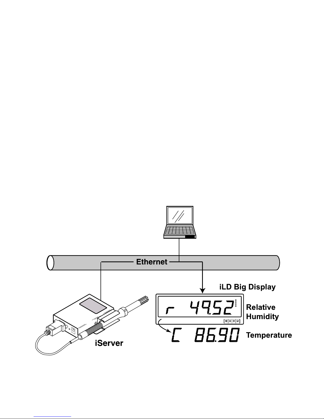
for tunneling. An iLD Big Display can display temperature and humidity received from an
iServer over the Ethernet or the Internet.
The following example illustrates how you can hookup an iServer and iLD to your
network:
Figure 1.1 iServer and iLD Big Display on the Ethernet Network
COL
ON
TX
RX
COMPUTER with
Standard Web Browser
and
3
4
PART 2 HARDWARE
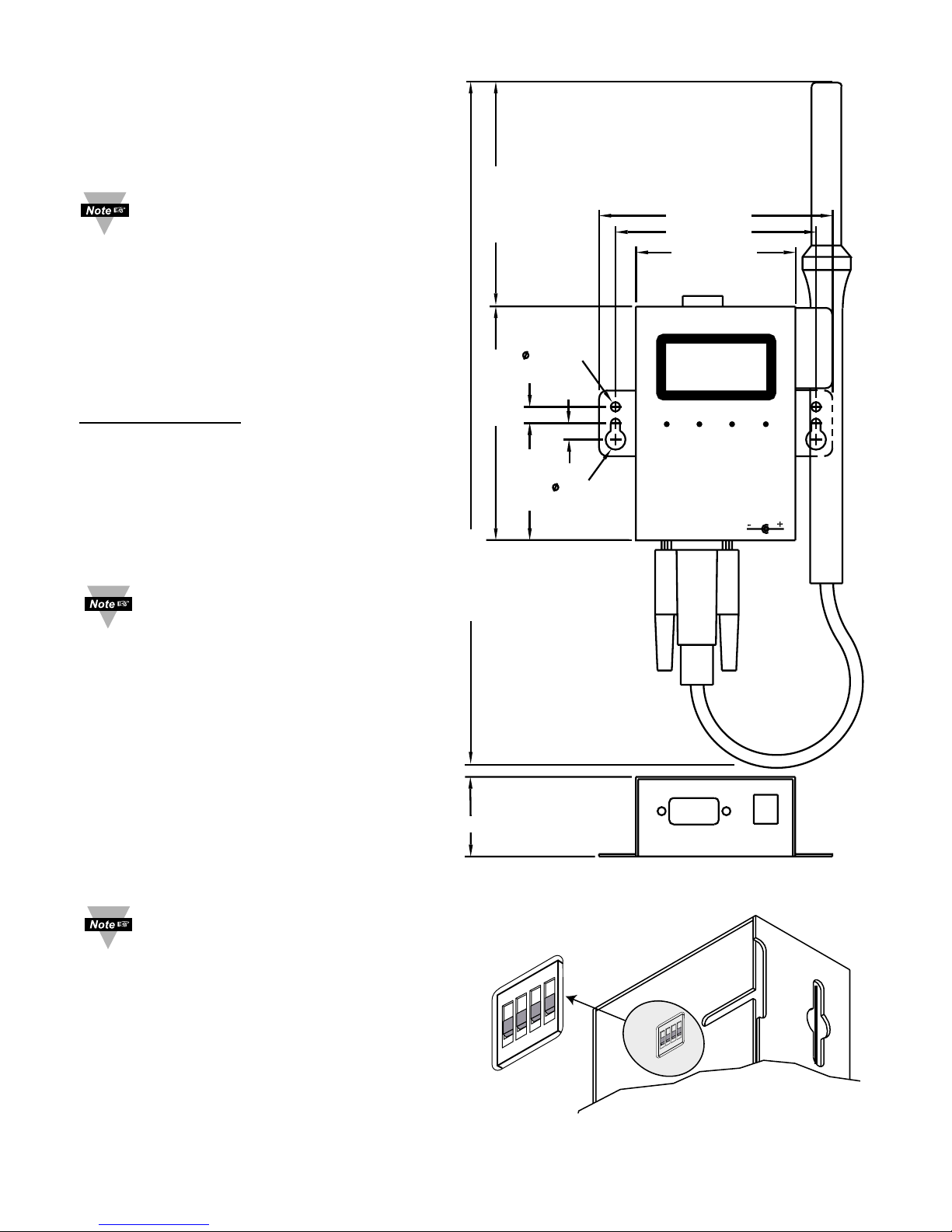
2.1 Mounting
Position unit where required. Mark and
drill holes as required.
If unit is to be mounted on a flat
surface, you may take the
bottom rubber feet off the unit.
1
4
3
2
OFF
ON
1
4
3
2
OFF
ON
9-12 Vdc
0.25 [6.4]
0.25 [6.4]
1.78 [45.2]
2.42 [61.6]
3.56 [90.3] 3.50 [88.9]
10.65 [270.4]
0.14 [3.6]
0.30 [7.7]
3.05 [77.5]
3.55 [90.2]
1.44 [36.6]
TEMPERATURE/HUMIDITY
Dimensions are in inches
with millimeters in [ ].
Figure 2.1 Mounting
Figure 2.2 DIP Switches
2.2 DIP Switches
The iServer is shipped with all DIP
switches in "OFF" position.
DIP
Switch Usage
1) N/C - not used
2) To change to default
factory settings
3) To enable/disable DHCP
4) N/C - not used
To set the iServer to factory
default settings, slide DIP switch
#2 to ON position. Power the
iServer on and wait about 10
seconds until the iServer fully
boots up. Set the DIP switch #2
back to OFF position (it does not
matter if the iServer is powered
ON or OFF, just make sure that
the DIP switch is set to OFF,
otherwise, every time the unit is
power-cycled the factory settings
will take over.
To enable the DHCP, besides
using DIP switch #3, set the
iServer’s IP address to 0.0.0.0.
An iServer with IP address of
0.0.0.0 will request an IP
address, gateway address, and
subnet mask from the DHCP
server over the Ethernet.
5
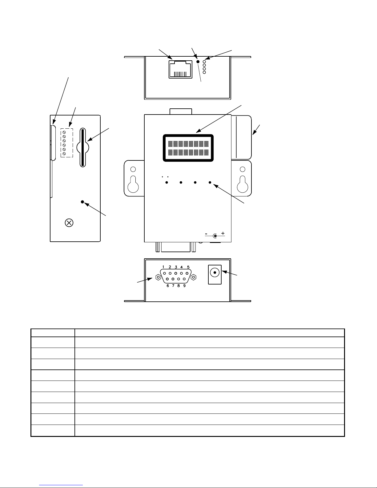
2.3 Parts of the iServer Unit
Figure 2.3 Parts of the iServer Unit
Table 2.1 Parts of iServer Unit
ETHERNET RJ45 interface for 10BASE-T connection.
RESET Button: Used for power reseting the iServer.
ACTIVITY LED (Red) Blinking: Indicates network activities (receiving or sending packets).
NET LINK LED (Green) Solid: Indicates good network link.
TX LED (Yellow) Blinking: Indicates transmitting data from iServer to flash memory card
RX LED (Green) Blinking: Indicates receiving data to iServer from flash memory card
°C/°F
Button: Change display units of measurement from °C to °F
TIME Button: Change display from DATE and TIME to RH and TEMP
STBY Button: Will stop the Flash from recording.
BKLT Button: Display Back Light
When using the small push buttons, hold the button until “WAIT” is displayed on the LCD and
then release.
9-12 Vdc
ACTIVITY
NETWORK LINK
TX-TRANSMIT
RX-RECEIVE
iServer Reset Button
iServer LEDs
iServer
RJ45 interface
dc Power Input
Probe
Handle
Clip
TEMPERATURE/HUMIDITY
C/ F STBYTIME BKLT
ETHERNET
RESET
1
8
Flash
Memory
Card
Reset
Button
Flash
Memory
Card
16 Digit
LCD Display
Buttons
DB9
Connector
Side or Bottom
Wire Entry for
Relay Connector
Removable Plug
Connector for Relays
under the Cover
6
1
6
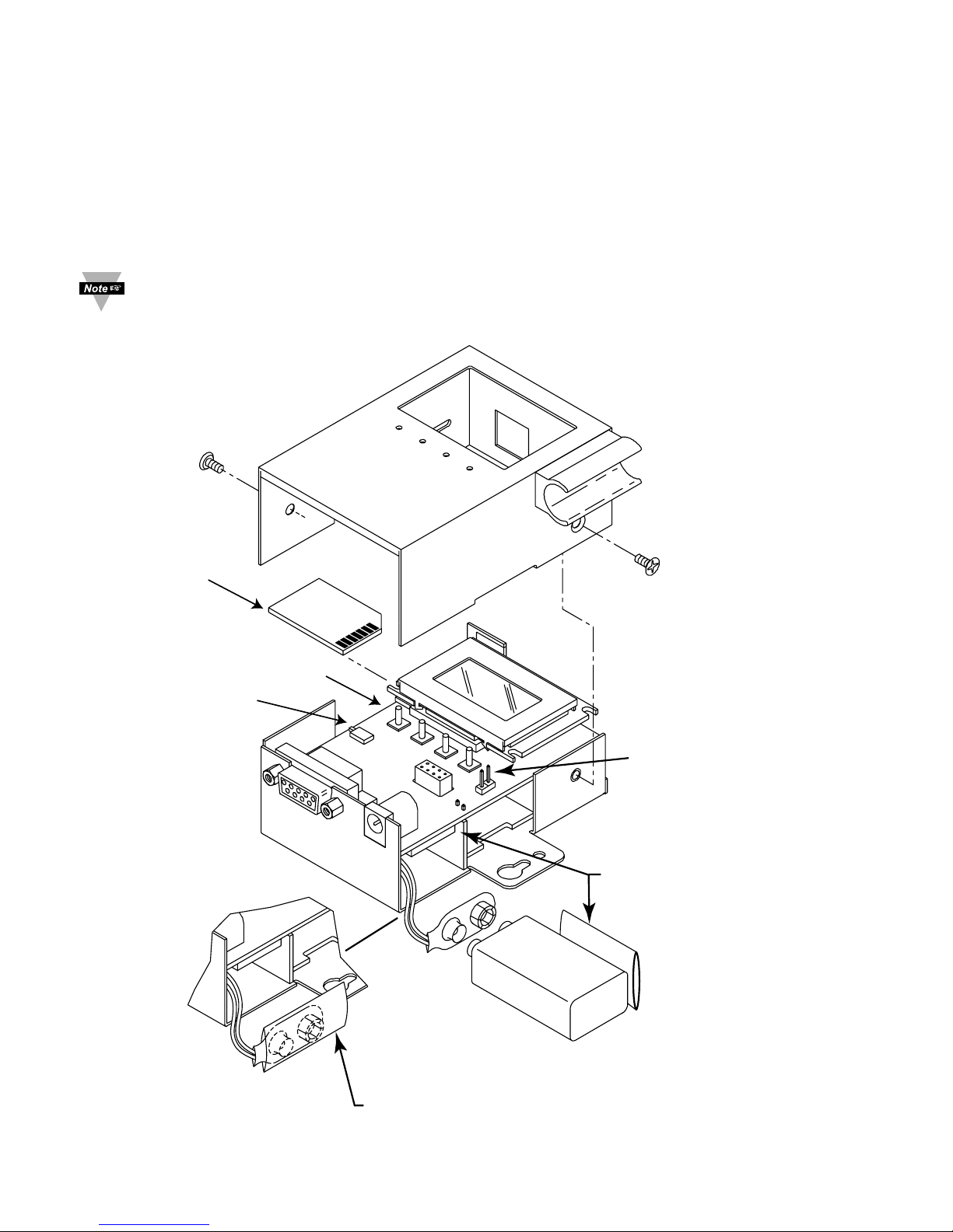
2.4 Disassembly Instruction
You may need to open the unit for one of the following reasons:
• To wire relay connector. (Refer to Figure 2.7)
• To connect or replace the battery.
• To change S5 jumper. In the absence of AC power, and if S5 is installed, the LCD
Backlight and iServer Board will be on and running on the battery power. Refer to
Section 2.7.
Disconnect the power supply before proceeding.
Remove Cover as shown.
Figure 2.4 Opening the Unit
MOUNTING
SCREWS (2)
KEEP INSULATOR
COVER ON BATTERY
CLIP WHEN BATTERY
IS NOT BEING USED
JTAG
S5
COVER
TRAY
FLASH
CARD
REMOVE BATTERY CLIP
INSULATOR COVER AND
STORE WHERE SHOWN
WHEN 9V BATTERY IS
BEING USED.
RELAY
CONNECTOR
FLASH
RESET
SWITCH
S5 (WITH LONG PINS)
7
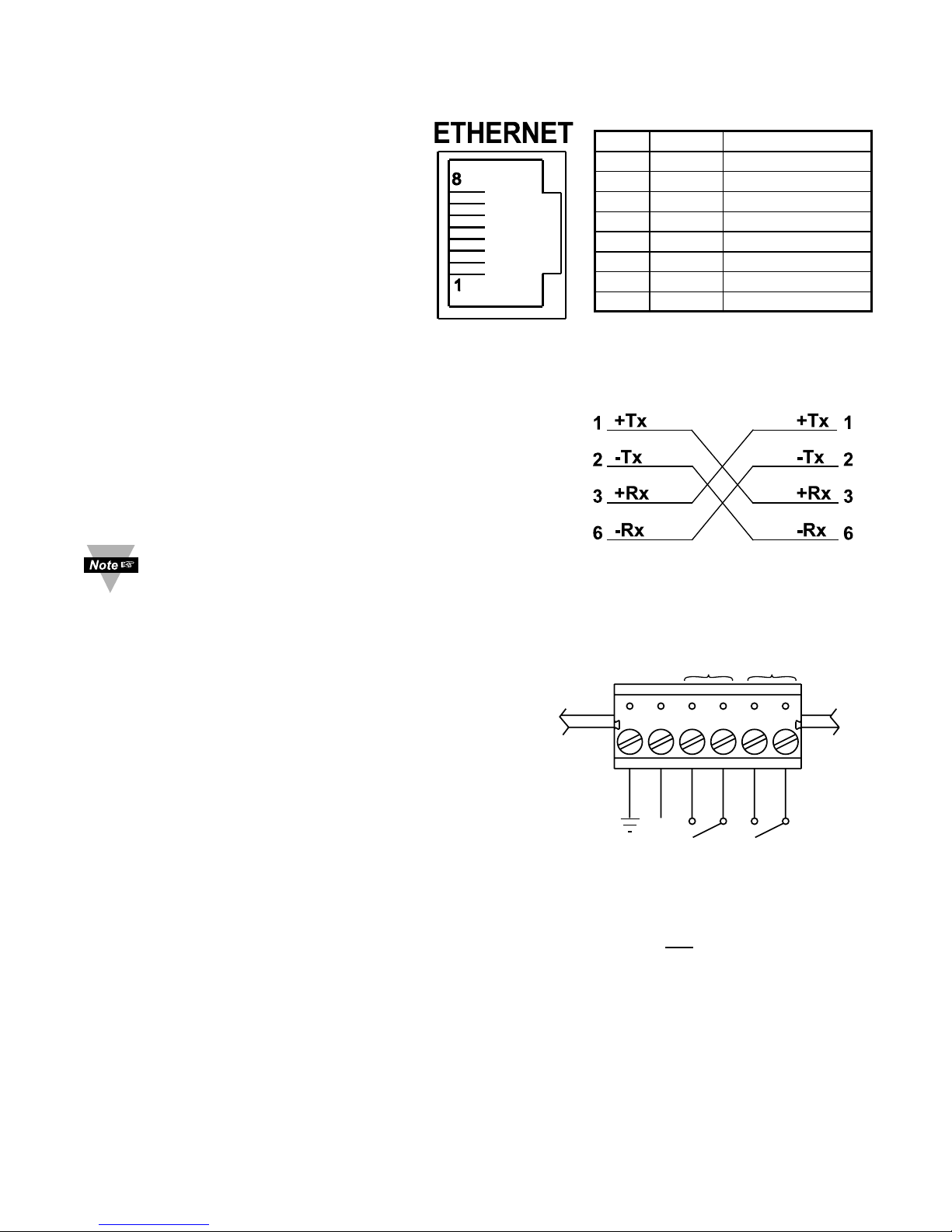
2.5 Network Communication Interfaces
2.5.1 10Base-T RJ-45 Pinout
The 10BASE-T Ethernet network
(RJ-45) system is used in the iServer
for network connectivity. The 10 Mbps
twisted-pair Ethernet system operates
over two pairs of wires. One pair is
used for receiving data signals and the
other pair is used for transmitting data
signals. This means that four pins of
the eight-pin connector are used.
2.5.2 10Base-T Crossover Wiring
When connecting the iServer directly to the computer’s
network port, the transmit data pins of the computer
should be wired to the receive data pins of the iServer,
and vice versa. The 10Base-T crossover cable with pin
connection assignments are shown below.
Use straight through cable for connecting the
iServer to an Ethernet hub. The ports on the
hub are already crossed.
2.6 Relay Wiring Connections
To access the Relay Connector you must remove
the cover, refer to Section 2.4.
2.7 Running on Battery Power
Battery and S5 jumper installed: if there is a power
outage the iServer board will be fully functional
including the LCD backlight “ON” for approximately
1 hour. You need to make sure that the LCD/PWR
field on the Configuration page of the iServer is set
to UPS (see Section 4.3.5.F)
Battery installed and S5 jumper in storage position (Factory Default): if there is a power
outage the LCD Backlight and iServer Ethernet board will not run, but
the unit will be
collecting and storing data for approximately 10 days.
When you first connect the battery, without the AC power adaptor, the unit will be in
“Sleep Mode”, in order to save power, and the LCD will display “Flash Standby”
(provided that S5 jumper is not installed). When battery is installed, plug the AC adaptor
into unit and push the Flash Reset Button (refer to Figure 2.3 or Figure 2.4). Unit is now
ready to be configured for recording the data. Also, if the AC adaptor is unplugged after
configuring the unit, it will be ready for recording data.
If you want to move the unit to a different location, remove AC adaptor and press the
Flash Reset button. Repeat the steps in the above paragraph.
623451
NO1
NO2
9 Vdc
RTN
COM2
COM1
RELAY 2 RELAY 1
Figure 2.7 Relay Connections
Figure 2.6 10Base-T
Crossover Cable Wiring
Pin Name Description
1 +Tx + Transmit Data
2 -Tx - Transmit Data
3 +RX + Receive Data
4 N/C Not Connected
5 N/C Not Connected
6 -Rx - Receive Data
7 N/C Not Connected
8 N/C Not Connected
Figure 2.5 RJ45 Pinout
8
PART 3
NETWORK CONFIGURATION
3.1 Network Protocols
The iServer can be connected to the network using standard TCP/IP protocols.
It also supports ARP, HTTP (WEB server), DHCP, DNS and Telnet protocols.
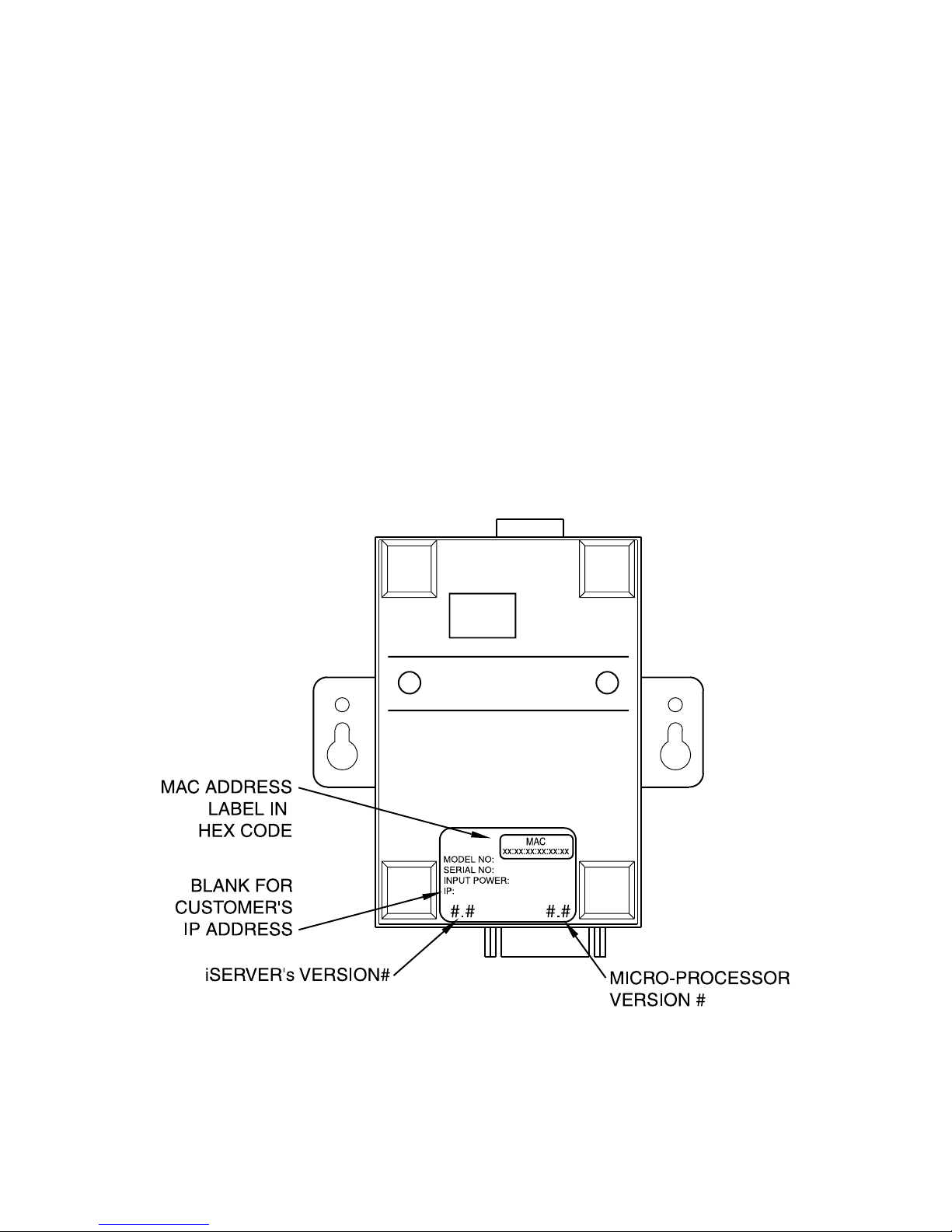
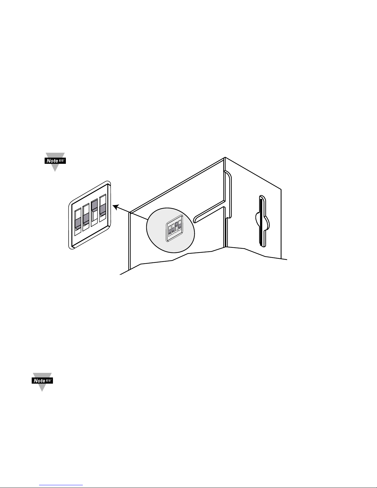
3.2 Ethernet (MAC) Address
MAC (Media Access Control) address is your computer's unique hardware number.
When you're connected to the LAN from your computer, a correspondence table relates
your IP address to your computer's physical (MAC) address. The MAC address can be
found on a label attached to your device and contains 6 bytes (12 characters) of
hexadecimal numbers XX:XX:XX:XX:XX:XX hex
For example: 0A:0C:3D:0B:0A:0B
There is room on the label to put your IP address. See Figure 3.1.
Figure 3.1 Labeling
9
3.3 DHCP
DHCP, Dynamic Host Configuration Protocol enables individual computers or devices to
extract their IP configurations from a server (DHCP server). If the DHCP is enabled on
your iServer, as soon as the iServer is connected to the network, there is an exchange of
information between DHCP server and the iServer. During this process the IP address,
the Gateway address, and the Subnet Mask will be assigned to the iServer by the DHCP
server. Note that the DHCP server must be configured correctly to do such assignment.
If fixed or static IP address is desired, the DHCP must be disabled. The iServer is
shipped with DHCP disabled (factory default). The DHCP can be enabled by setting the
DIP switch # 3 to the “ON” position (refer to Figure 3.2).
Figure 3.2 DIP Switch on the Bottom Side of iServer
3.4 DNS
DNS, Domain Name System enables individual computers and devices to be recognized
over a network based on a specific name instead of an IP address. For example, instead
of having to use http://128.100.101.254 (IP address), you would use only http://eis03ec
or any eight character name stored as Host Name under Access Control menu in the
iServer Home Page. The default DNS name for an iServer is "eis" followed by the last
four digits of the MAC address of that particular iServer.
1. It is very important to communicate with the network administrator in order to
understand the DHCP and its existing configurations on the host server,
before enabling the DHCP on the iServer.
2. The iServers are shipped with a default static IP address of
128.100.101.254 and Subnet Mask of 255.255.0.0.
3. On Novell networks or Windows 2000 Server where the DCHP is an updated
function of DNS, this feature may be beneficial since a particular name can
be assigned eliminating the need for the IP address, as described in
Section 3.4.
1
4
3
2
OFF
ON
1
4
3
2
OFF
ON
DIP switch # 3 shown
in “ON” position

3.5 IP Address
Every active device connected to the TCP/IP network must have a unique IP address.
This IP address is used to build a connection to the iServer. Every computer using
TCP/IP should have a unique 32-bit address. It is divided into two portions, the network
ID and the host ID. For instance, every computer on the same network uses the same
network ID. At the same time, all of them have a different host ID. For more details about
the IP address see Appendix B.
3.5.1 Default IP Address
The iServer is shipped with a default IP address set to 128.100.101.254 and Subnet
Mask of 255.255.0.0. If you are going to use a Web browser or Telnet program to access
the iServer using its default IP address, make sure that the PC from which you’re
establishing the connection has an IP address that is in the same range as the iServer’s
IP address (128.100.x.x, where x can be any number from 1 to 254. Note that your PC’s
IP address cannot be the same as the iServer’s IP address). You also need to make
sure that your PC’s Subnet Mask is 255.255.0.0. This is a good way to access the
iServer over the network and make any configuration changes needed. If the factory
default address is already in use on your network, use an Ethernet crossover cable
between your computer and the iServer and modify the IP address or any other settings
within the iServer.
3.6 Port Number
All TCP connections are defined by the IP address and a port number. A port number is
an internal address that provides an interface between an application running on your
computer and the network through the TCP/IP protocol.
There are three default TCP socket port numbers assigned to the iServer:
1. Port (socket) number 1000 when using HTTPGET program.
2. Port (socket) number 2000 when trying to access the sensor (probe) connected to
the port of the iServer to receive ASCII data.
3. Port (socket) number 2002 when trying to access the iServer itself for Power
Recycling the iServer remotely. This can be done using Windows standard Telnet
application.
Telnet stands for Telecommunications Network, is a protocol that provides a way for
users (or clients) to connect to computers (or servers) on a network, whether in the next
building or across the world.
Example: C:\>Telnet 128.100.101.254 2002
You will then get the following screen.
Figure 3.3 Telnet Login into the iServer
You can also open a Telnet session using Tera Term Pro (this can be downloaded from
http://download.cnet.com/downloads/0-10062-100-890547.html
).
10
10
Flash Memory Temperature/Humidity Firmware Version 1.00
Admin. Password:00000000
Admin. Login Successful
reset
The unit will reset in 5 seconds
_
The default
Admin. Password
Type "reset"
to reboot
the server
11
PART 4
OPERATIONS
This iServer can be used and configured in several ways, depending on user’s
preference and network setup. It can be configured using a Web browser, like Netscape
or Internet Explorer. It can also be configured using NEWPORT’s iCONNECT
Configuration Software.
If DHCP and DNS servers are used, the connection is very simple, you do not need to
worry about IP address, MAC address, or network conflicts, all of these issues are solved
for you by your network DHCP and DNS server. All that is left for you to do, is to use a
straight network cable to connect the iServer to a hub and power it up.
Instead of connecting the iServer directly to your network, you can configure your
PC’s network connection with an IP address (128.100.x.x) that is in the same range
as the iServer’s default IP address (128.100.101.254) and connect to the iServer
using a cross-over network cable between your PC’s network port and the iServer.
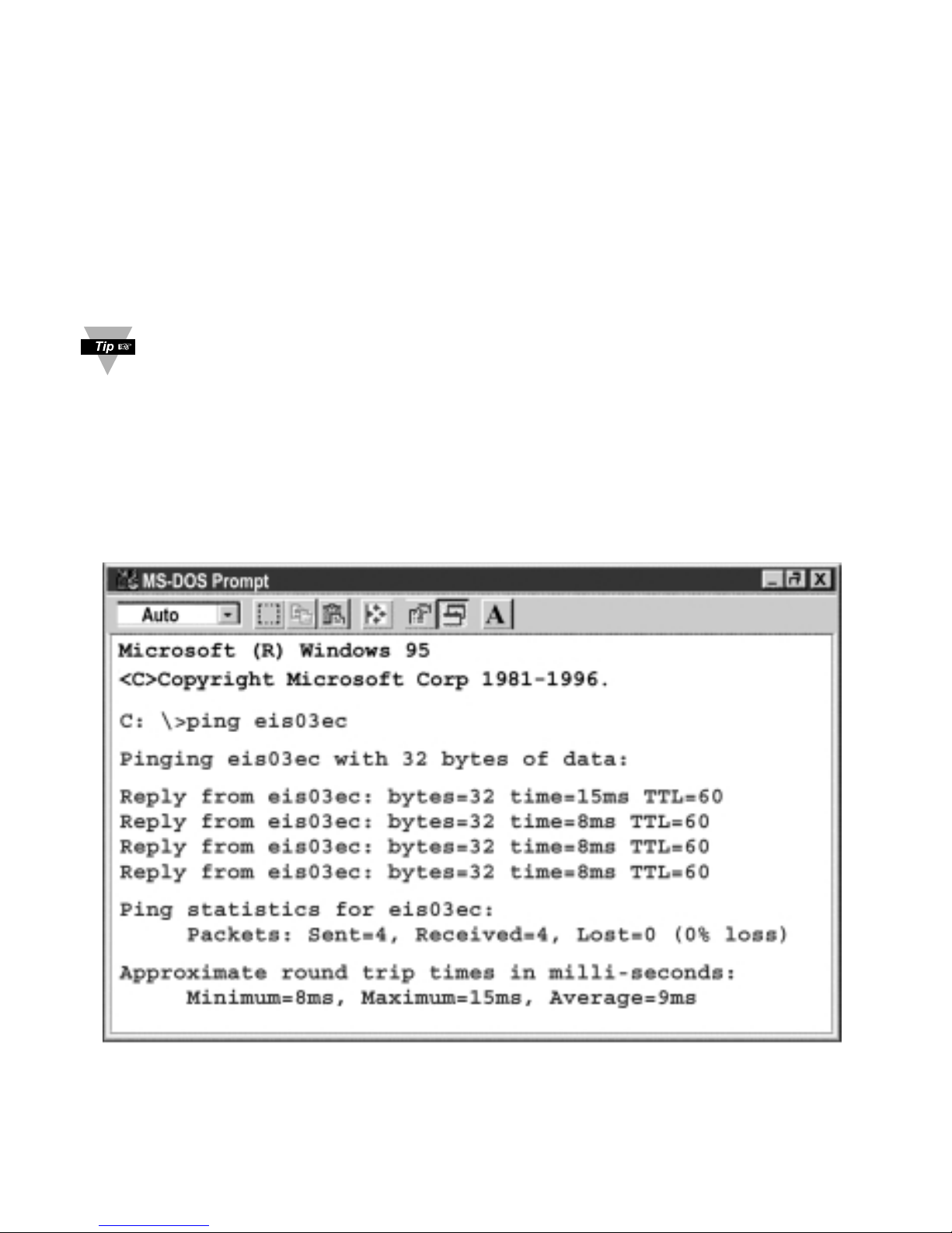
Go to your computer that is connected to the same network and from the MS-DOS Prompt
window type "ping 128.100.101.254” and press Enter. If DHCP and DNS servers are
used type “ping eisxxx”, where xxxx are the last four digits of the iServer’s MAC address,
located on the back of the device. You should get a reply as shown in Figure 4.1.
4.0 Testing the Connection
Figure 4.1 Pinging eis03ec MS-DOS Prompt
This proves that the connection is proper and you can get into configuration or run mode
using the Telnet or Web browser.
 Loading...