


Newport Medical Instruments, Inc.
Newport HT70 Ventilator
Operating Manual
for Plus Model
OPRHT70-2 Rev. F
06/13
|
Newport Medical Instruments, Inc. |
|
|
1620 Sunflower Ave. |
|
|
Costa Mesa, CA 92626 |
|
|
Tel: 1.714.427.5811 |
|
|
Tel: 1.800.451.3111 (USA Only) |
|
|
Fax: 1.714.427.0489 |
|
|
Customer Service ext. 282 |
|
0344 |
www.ventilators.com |
|
email: Info@ventilators.com |
||
|

Manual Revision History
HT70 Operating Manual OPRHT70-2
Revisions |
Date |
Description |
Rev A |
October 2011 |
New release |
Rev B |
November 2011 |
Miscellaneous type corrections, |
|
|
text change on page 3-3, 7-1, 7-3 |
|
|
regarding Power Pac. |
Rev C |
May 2012 |
Add Operating Manual Reivison. |
|
|
Notice regarding the following |
|
|
change: Pulse Oximeter accessory |
|
|
and related functions no longer |
|
|
available. |
Rev D |
July 2012 |
Software update ver. P05.12.10 |
|
|
and above, Remove references |
|
|
to optional Pulse Oximeter (not |
|
|
available), Change Slope/Rise |
|
|
setting was: 1 is fastest, is: 1 is |
|
|
slowest. |
Rev E |
November 2012 |
Update to correct image reversal |
|
|
in F-1 and F-2, callout labels on |
|
|
various drawings converted to |
|
|
numbers and referenced in text or |
|
|
added to table. Remove reference |
|
|
to Aequitron nurse call systems. |
|
|
Replace warranty details with who |
|
|
to contact information. |
Rev F |
June 2013 |
Add information about the |
|
|
Aequitron Remote Alarm System. |
OPRHT70-2 F0613

Contact Information
Thank you for using the Newport HT70 family of ventilators. With the HT70 you not only get a great ventilator, you get the support of Newport Medical. Since 1981 we have maintained a focused commitment to the design, production and sale of ventilators. We have dedicated our efforts to providing ventilators that are easy to use, clinically versatile, and cost effective.
We know that ventilatory support is critical in emergency and critical care situations. But for many of our customers, it is also a part of their daily lifestyle. The HT70 Ventilators offer home care users the expanded mobility that allows them to experience more freedom in their lives than many have ever known before.
We have designed this manual to be comprehensive and still very user friendly. For the best performance from your HT70 Ventilator, please take the time to review this manual completely.
See our contact information on the following page for complete details.
OPRHT70-2 F0613

Contact Information
Contact Information
Telephone:
+1.714.427.5811 1.800.451.3111 (US only)
Fax:
+1.714.427.0489
Departments:
Customer Service (Ext. 282)
Technical Services (Ext. 500) available 24/7
Clinical Support (Ext. 123) available 24/7
Operational Hours:
Days: Monday through Friday
Hours: 8:00 am to 5:00 pm (PST)
Emergency After-hours: 24-Hour Clinical and Technical Support
Email:
Customer Service: customers@ventilators.com
Clinical Education and Support: clinical@ventilators.com Technical Education and Support: techservice@ventilators.com
Internet:
www.ventilators.com
Shipping Address:
Newport Medical Instruments
Attn: Receiving Department
1620 Sunflower Avenue
Costa Mesa, CA 92626, USA
EC REP
Authorized European Representative
Emergo Europe
Molenstraat 15
2513 BH, The Hague
The Netherlands
OPRHT70-2 F0613
FOLDOUT DRAWINGS
Use the following drawings as reference while reviewing the manual sections
Unfold to view drawing on reverse side
OPRHT70-2 F0613

Figure F-1 English VersionFront Panel Overview
9
1
10
|
11 |
||||
2 |
|
|
|
|
12 |
|
|
|
|
||
3 |
|
|
|
|
|
|
13 |
||||
4 |
|
|
14 |
||
|
|||||
5
15
6
16
7
8
1.Breath Delivery Indicator LED. Flashes green with every breath delivered by the ventilator.
2.External Power LED. Lights green whenever external power is connected. This also indicates that the Internal Dual Battery System is being charged.
3.Manual Inflation button. Press and hold this button to deliver flow to the patient. The ventilator will deliver flow at the current settings while the button is pressed. Flow delivery is limited to a maximum of 3 seconds or until the High Pressure alarm setting is reached.
4.Brightness button. Press this button repeatedly to scroll to one of four screen brightness levels.
5.Device Alert LED. Lights red when there is a device alarm. Take the ventilator out of service and use an alternate means of ventilation until resolved.
6.Patient Gas Output. Attach patient breathing circuit tubing here.
7.Proximal Pressure Line connector. Attach proximal pressure tubing here.
8.Exhalation Valve Drive Tubing connector. Attach exhalation valve drive tubing here.
9.Alarm Violation LEDs. LEDs in the handle light to indicate alarm conditions.
10.Alarm Silence/Reset button. Press this button to silence the audible alarm for 1 minute. Once an alarm condition has been corrected, press this button to clear/ reset the alarm message and latched indicators.
11.Alarm Silence LED. Remains lit during the one minute alarm silence period.
12.Cancel button. Press this button if you want to cancel changes that have not already been accepted.
13.Accept button. Press this button to accept/confirm all changes made to control settings.
14.σ Up / τ Down Arrow buttons. Press to change a highlighted parameter up/down by one unit. Hold down continuously and the parameter will change at an increasingly quicker pace.
15.Touch Screen User Interface. Touch screen to access alarms and parameter settings.
16.Flow Sensor connector. Attach on-airway flow sensor here.
F-1
OPRHT70-2 F0613
Unfold to view drawing on reverse side
OPRHT70-2 F0613

Figure F-2 Symbols VersionFront Panel Overview
1
2
3
4
5
6
7
8
9
10
11
12
13
14
15
16
1.Breath Delivery Indicator LED. Flashes green with every breath delivered by the ventilator.
2.External Power LED. Lights green whenever external power is connected. This also indicates that the Internal Dual Battery System is being charged.
3.Manual Inflation button. Press and hold this button to deliver flow to the patient. The ventilator will deliver flow at the current settings while the button is pressed. Flow delivery is limited to a maximum of 3 seconds or until the High Pressure alarm setting is reached.
4.Brightness button. Press this button repeatedly to scroll to one of four screen brightness levels.
5.Device Alert LED. Lights red when there is a device alarm. Take the ventilator out of service and use an alternate means of ventilation until resolved.
6.Patient Gas Output. Attach patient breathing circuit tubing here.
7.Proximal Pressure Line connector. Attach proximal pressure tubing here.
8.Exhalation Valve Drive Tubing connector. Attach exhalation valve drive tubing here.
9.Alarm Violation LEDs. LEDs in the handle light to indicate alarm conditions.
10.Alarm Silence/Reset button. Press this button to silence the audible alarm for 1 minute. Once an alarm condition has been corrected, press this button to clear/ reset the alarm message and latched indicators.
11.Alarm Silence LED. Remains lit during the one minute alarm silence period.
12.Cancel button. Press this button if you want to cancel changes that have not already been accepted.
13.Accept button. Press this button to accept/confirm all changes made to control settings.
14.σ Up / τ Down Arrow buttons. Press to change a highlighted parameter up/down by one unit. Hold down continuously and the parameter will change at an increasingly quicker pace.
15.Touch Screen User Interface. Touch screen to access alarms and parameter settings.
16.Flow Sensor connector. Attach on-airway flow sensor here.
F-2
OPRHT70-2 F0613

Unfold to view drawing on reverse side
OPRHT70-2 F0613

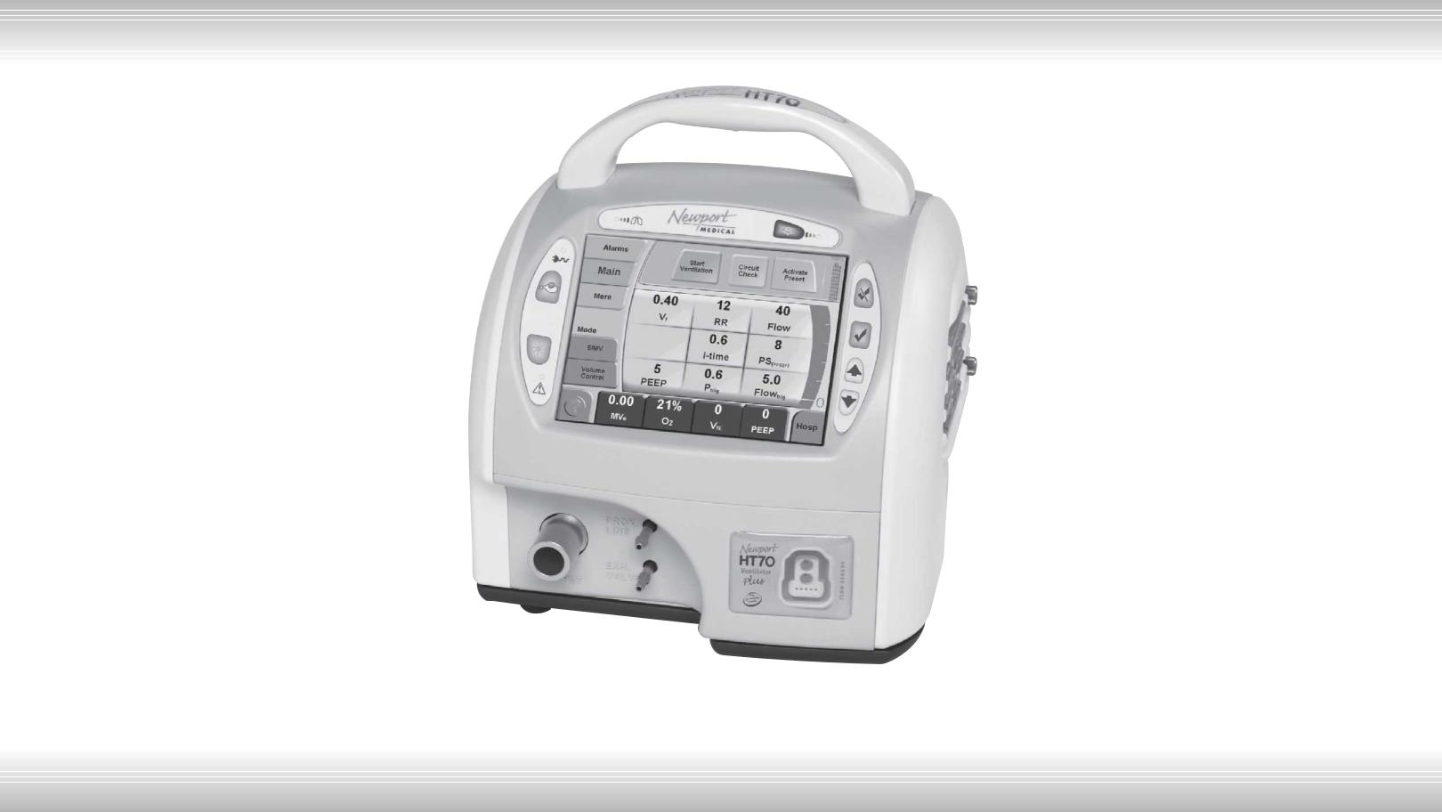
Figure F-3 HT70 Plus Model Touch Screen (Hospital Domain)
1
2
3
4
5
6
 7
7
8
9
10
11/12
1.Screen Selections buttons. Touching any one of these buttons will take you to the new screen. The More screen includes links to Event, Trends, Wave and Utility screens.
2.Mode selector. Touching this button scrolls through the mode choices. The mode will not change until you press the Accept button.
3.Breath Type selector. Touching this button toggles the breath type choice. The breath type will not change until you press the Accept button.
4.Help button. Touching this button enables a tutorial for each feature on the screen. Touch the help button then touch any button for an explanation of that feature.
5.Monitored Data buttons. Touching any one of these four buttons opens a screen with a view of monitored parameter choices to display in that button.
6.Message display. This area shows all informational and alarm messages and current NIV selection, mode, and breath type selection. During an alarm violation this area will light red for High Priority, amber for Medium Priority and yellow for Low Priority alarms and display the alarm message.
7.Battery Charge Level indicator. Shows the charge level of the “Power Pac” battery pack (blue icon) during external power or Power Pac use or the charge level of the Backup Battery (red icon) during Backup Battery use.
8.Pressure Bar. Indicates dynamic pressure in the patient circuit in green, the High and Low Pressure Alarm settings in red and the peak pressure of the last breath in green.
9.Parameter Setting buttons. Touching any one of these buttons will activate the parameter to allow adjustments.
10.Patient Effort indicator. Flashes green to show a spontaneous patient effort.
11.Domain button. The HT70 can be set up in one of three Domains: Basic, Transport and Hospital. Touch to scroll through the Domain choices. Press Accept to confirm choice.
12.AutoLock/Unlock button. This button is only visible if Auto Lock is enabled and the panel is locked. Touch and hold for 3 seconds to unlock touch screen buttons.
NOTE: While operating on battery power with Power Save enabled and all alarms cleared, the touch screen will go to sleep after 2 minutes. Just touch the screen to bring it back into view.
F-3
OPRHT70-2 F0613

Table of Contents
1 Introduction
Brief Device Description.............................................................. |
1-1 |
Intended Use............................................................................... |
1-3 |
Warnings, Cautions and Notes................................................... |
1-3 |
2 Overview of Controls, Screens and Connectors
Front Panel Overview.................................................................. |
2-1 |
Touch Screens Overview............................................................ |
2-1 |
Internal Dual Battery System Overview...................................... |
2-1 |
Rear Panel Overview................................................................... |
2-2 |
Right Side Overview.................................................................... |
2-3 |
Left Side Overview...................................................................... |
2-3 |
Bottom Panel Labeling................................................................ |
2-4 |
3 Set up and Pre-use Preparations
Unpack the HT70 Ventilator........................................................ |
3-1 |
Assemble the Ventilator.............................................................. |
3-2 |
Connect to AC Power................................................................. |
3-2 |
Using the Power Switch.............................................................. |
3-3 |
Make Parameter Changes.......................................................... |
3-4 |
Attach a Patient Circuit............................................................... |
3-4 |
For use with a third party humidifier..................................... |
3-5 |
For use with an HME............................................................. |
3-8 |
Using the On-airway Flow Sensor....................................... |
3-10 |
Connect Optional Accessories.................................................. |
3-11 |
Air/Oxygen Entrainment Mixer............................................. |
3-11 |
Low Flow Oxygen Reservoir............................................... |
3-12 |
D.C. Auto Lighter Power Adapter........................................ |
3-14 |
Aequitron Remote Alarm Cable Accessory........................ |
3-14 |
4 Navigating the HT70 Screens
Touchscreen (Graphical User Interface) Layout.......................... |
4-1 |
Primary Screen Buttons and Displays........................................ |
4-1 |
Ventilator Settings Adjustment.................................................... |
4-4 |
Start Up Screen Navigation (Standby Condition Only)............... |
4-4 |
Circuit Check Button............................................................. |
4-5 |
How to Perform a Circuit Check..................................... |
4-5 |
If the Circuit Check Fails................................................. |
4-6 |
Activate Preset Button.......................................................... |
4-7 |
How to Use a Preset....................................................... |
4-7 |
Start Ventilation Button............................................................... |
4-7 |
OPRHT70-2 F0613

Table of Contents
Alarms Screen Navigation........................................................... |
4-8 |
Main Screen Navigation.............................................................. |
4-9 |
More Screen Navigation............................................................ |
4-11 |
More Screen Details............................................................ |
4-13 |
Events............................................................................ |
4-13 |
Trends............................................................................ |
4-14 |
Waves............................................................................ |
4-15 |
O2 Cylinder Data Screen............................................... |
4-16 |
Calibrate O2 Monitor...................................................... |
4-17 |
Utility Screen............................................................................. |
4-18 |
Utility Screen Details........................................................... |
4-19 |
Time/Altitude Screen..................................................... |
4-19 |
Customize Settings Screen........................................... |
4-20 |
Custom Presets............................................................. |
4-21 |
Back Up Ventilation....................................................... |
4-22 |
Domain Navigation.................................................................... |
4-23 |
Hospital............................................................................... |
4-23 |
Transport............................................................................. |
4-24 |
Basic ................................................................................. |
4-25 |
5 Operating the HT70 Ventilator
Quick Check Procedure.............................................................. |
5-1 |
Introduction........................................................................... |
5-1 |
Equipment Needed............................................................... |
5-1 |
Pretest Inspection................................................................. |
5-1 |
Set Up ................................................................................... |
5-1 |
Standard Test Settings.......................................................... |
5-2 |
Quick Check Procedure........................................................ |
5-2 |
Pass / Fail Check Off Sheet.................................................. |
5-4 |
Patient Setup Procedure............................................................. |
5-5 |
Troubleshooting Guide................................................................ |
5-7 |
6 Ventilator Alarms
Setting Alarms............................................................................. |
6-1 |
Alarm Quickset...................................................................... |
6-1 |
Alarm Indicators.......................................................................... |
6-2 |
Alarm Silence/Reset Button.................................................. |
6-2 |
Alarm Silence LED................................................................. |
6-2 |
User Adjustable Alarms.............................................................. |
6-2 |
Backup Ventilation...................................................................... |
6-6 |
Automatic Alarms........................................................................ |
6-6 |
Battery Alarms............................................................................ |
6-9 |
OPRHT70-2 F0613

Table of Contents
|
|
7 Battery Operation |
|
Internal Dual Battery System....................................................... |
7-1 |
Power Pac Battery Pack.............................................................. |
7-1 |
Backup Battery........................................................................... |
7-2 |
Conditions that Affect Battery Use Time.................................... |
7-2 |
Check the Battery Charge Level and Battery Time Estimator.... |
7-3 |
Best Use Tips.............................................................................. |
7-3 |
Battery System Maintenance...................................................... |
7-4 |
Power Pac Battery Pack Removal.............................................. |
7-4 |
Battery Alarms Overview............................................................ |
7-5 |
Power Accessories..................................................................... |
7-6 |
|
|
8 Cleaning and Maintenance |
|
Cleaning and Disinfecting........................................................... |
8-1 |
Ventilator ................................................................................... |
8-1 |
Accessories................................................................................. |
8-2 |
Low Flow Oxygen Reservoir................................................. |
8-2 |
Air/Oxygen Entrainment Mixer.............................................. |
8-2 |
Reusable Breathing Circuits....................................................... |
8-3 |
Air Intake Filter............................................................................ |
8-3 |
Proximal Inline Filter.................................................................... |
8-4 |
Maintenance Guidelines.............................................................. |
8-4 |
Routine Maintenance............................................................ |
8-4 |
6 Month Maintenance........................................................... |
8-5 |
12 Month Maintenance.......................................................... |
8-5 |
24 Month Maintenance......................................................... |
8-5 |
15,000 Hour Maintenance..................................................... |
8-6 |
General Warnings........................................................................ |
8-6 |
Factory Maintenance or Repair................................................... |
8-7 |
Repacking/Return Information.................................................... |
8-7 |
9 Specifications
Front Panel Buttons - Symbols Version...................................... |
9-1 |
Miscellaneous Reference Symbols............................................. |
9-2 |
Controls / Monitors..................................................................... |
9-3 |
Monitor Data Selections.............................................................. |
9-4 |
Front Panel Membrane Buttons and Indicators.......................... |
9-4 |
Alarms ................................................................................... |
9-5 |
User Adjustable..................................................................... |
9-5 |
Automatic.............................................................................. |
9-5 |
Hardware Requirements............................................................. |
9-7 |
Environment................................................................................ |
9-8 |
Size and Weight.......................................................................... |
9-8 |
OPRHT70-2 F0613

Table of Contents
Factory Default Parameters........................................................ |
9-9 |
Miscellaneous ............................................................................ |
9-9 |
(optional) Air / Oxygen Entrainment Mixer.................................. |
9-9 |
(optional) Low Flow Oxygen Reservoir........................................ |
9-9 |
Regulatory and Agency Standards........................................... |
9-10 |
10 Explanations of Modes and Controls
Explanation of Modes and Controls......................................... |
10-1 |
Foldout Diagrams
English Version - Front Panel Overview...................................... |
F-1 |
Symbols Version - Front Panel Overview.................................... |
F-2 |
HT70 Plus Model Touch Screen................................................. |
F-3 |
OPRHT70-2 F0613

ISection 1:
ntroduction
Introduction
Section 1: |
|
Introduction |
|
Brief Device Description.................................... |
1-1 |
Intended Use....................................................... |
1-3 |
Warnings, Cautions and Notes.......................... |
1-4 |

Introduction 1
Brief Device Description
The Newport HT70 family of ventilators are state of the art ventilators that combine ruggedness, ease of use and clinical proficiency with exceptional mobility to provide ventilatory support for infant, pediatric and adult patients in emergency care, transport, critical care, subacute care and home care applications. They are also ideal for emergency preparedness applications.
The compact, lightweight HT70 ventilator is built for hard work with a durable polymer exterior and robust overall design that stands up to harsh environments.
The HT70 Ventilator defines ease of use with all essential controls at your fingertips using a simple membrane button and touch screen combination. There are no complicated menus or difficult sequences to follow in order to make necessary adjustments for common operations.
A three-tiered management domain system makes it very easy for critical caregivers to manage all controls while providing quick access to the more essential elements in transport situations and significantly enhanced safety and simplicity in the homecare environment.
Sophisticated Clinical Capabilities
In addition to its durability and ease of use, the HT70 ventilator offers the complete array of clinical capabilities needed for managing critical patients.
The twin micro-piston pump’s ability to deliver a variable flow enables the HT70 to provide a full range of operating modes and breath types with servo-controlled, leak-compensated PEEP. Leak compensation helps to improve triggering and avoid auto-triggering when a leak is present. The HT70 may be used with an endotracheal tube, tracheal tube, face mask, nasal mask or prongs, or mouthpiece.
There are 3 models for the HT70 series of ventilators:
HT70S |
HT70 Basic for use when Pressure Support is not |
|
needed. |
HT70 |
HT70 Classic, adds Pressure Support and related |
|
parameters and Trends screen |
HT70PM |
HT70 Plus, adds on-airway flow sensor option with |
|
graphics, flow trigger and exhaled volumes |
The HT70 Basic and Classic models provide monitoring of inspiratory tidal volume (every breath), inspiratory minute volume, total respiratory rate, peak pressure, mean pressure and baseline (PEEP) pressure. Real-time patient circuit pressure is displayed at all times
OPRHT70-2 F0613 |
1-1 |

1 Introduction
on the airway pressure gauge on the face panel. A comprehensive alarm system is built-in to alert the user to violations of user-set or ventilator safety limits. An optional built-in oxygen sensor allows monitoring of O2 with high and low O2 alarms.
The HT70 Plus model adds an on-airway flow sensor with onscreen graphics, exhaled tidal and minute volume monitoring/alarms, and flow trigger. This manual describes the HT70 Plus model and will denote features that are not available on the HT70 and HT70S models.
Gas delivery to the patient may be enriched with oxygen (0.21-1.00) using either the optional Air Oxygen Entrainment (50 psi) Mixer or optional Low Flow Oxygen Reservoir.
Exceptional Mobility
The ventilator’s unique design provides maximum mobility and safety for short or long distance transport of critically ill patients and also for patients who are going about their normal activities of daily life. This exceptional mobility is derived from two sources: Newport’s patented, power conserving dual-micro-piston technology which eliminates the need for an external compressed gas source, and the Internal Dual Battery System which allows virtually continuous use from battery power through hot-swappable technology.
The HT70’s micro-pistons use a fraction of the power that is consumed by turbines and blowers. This enables longer battery use time. Our patented system also uses considerably less supplemental oxygen than turbine or blower systems, again improving mobility for transport or homecare use. The superior technology of our micropiston system over the turbine and blower systems allow the HT70
to ventilate safely over a wide range of environmental conditions and altitudes.
The HT70’s twin micro-piston internal pump is made of mechanically moving components. As with any other gas delivery system
made of moving components, it may emit a minor level of noise during operation. This is not a malfunction and does not affect the performance of the ventilator.
The Internal Dual Battery System consists of two independent but coordinated lithium ion batteries, the Power Pac battery, located on the back of the ventilator and the Backup Battery inside the ventilator. The Internal Dual Battery System can provide up to 10 hours of operation at standard settings when new and fully charged. This system assures continued support during transport, daily activities or power outages.
1-2 |
OPRHT70-2 F0613 |

Introduction 1
The detachable Power Pac is ‘hot-swappable’. That is, if more battery time is needed, a depleted Power Pac can easily be removed from the back of the HT70 and replaced with a recharged Power Pac without interrupting ventilation. No tools are needed. The secondary Backup Battery maintains operation without interruption when the Power Pac is swapped out and also provides a minimum of 30 minutes of full operation when all other power sources are depleted. The Power Pac weighs two pounds and is charged anytime the ventilator is connected to an external power source (AC or DC). It can also be charged separately.
The HT70 may be operated from a variety of AC (100-240 VAC @ 50 / 60 Hz) or DC (12-24 VDC) external power sources or from the Internal Dual Battery System. The optional DC Auto Lighter Power Adapter accessory enables connection to an automobile-type DC outlet. Any time the ventilator is connected to external power, both batteries in the Internal Dual Battery System are charging, whether or not the ventilator is in use.
Travel Certified
The HT70 has been tested for and meets requirements for use in helicopter and fixed wing transport and for use on commercial airlines. Before traveling, be sure to speak with your airline representative about their particular concerns and clear all of your equipment with them well before your departure. The labeling that the FAA requires to be on the ventilator is located on the bottom of the HT70.
Intended Use
Newport HT70 family of ventilators is intended to provide continuous or intermittent positive pressure mechanical ventilatory support for the care of individuals who require mechanical ventilation through invasive or noninvasive interfaces.
Specifically, the Newport HT70 family of ventilators is applicable for infant, pediatric and adult patients greater than or equal to 5 kg (11 lbs) in hospital, sub-acute, emergency department, and home
care environments as well as for transport and emergency response applications.
NOTE: Federal law (US) restricts sale by or on the order of a physician.
OPRHT70-2 F0613 |
1-3 |

1 Introduction
Ventilator Configurations
Newport Medical offers five configurations for the 3 models in the HT70 family of ventilators. See Table 1. In addition, the front control panel labeling is available in various languages and regional power cords, i.e. North American, European, etc., can be specified. See your Newport Medical Representative for details.
Table 1
Part Number |
Description |
Distinguishing Features |
|
|
|
|
|
HT70PM |
|
Full featured with Flow sensor, |
|
HT70 Plus |
graphics and built-in oxygen monitor |
||
|
|
with alarms. |
|
HT70 |
HT70, w/o |
Classic features |
|
Oxygen Sensor |
No built-in oxygen monitor |
||
|
|||
HT70M |
HT70, with |
Classic features |
|
Includes built-in oxygen monitor with |
|||
Oxygen Sensor |
|||
|
alarms |
||
|
|
||
|
|
|
|
|
|
Classic features except: |
|
HT70S |
HT70, Basic w/o |
• No Pressure Support or Pressure |
|
Support parameters |
|||
Oxygen Sensor |
|||
|
• No Trends |
||
|
|
||
|
|
• No built-in oxygen monitor |
|
|
|
Classic features except: |
|
|
|
• No Pressure Support or Pressure |
|
HT70SM |
HT70, Basic with |
Support parameters |
|
Oxygen Sensor |
• No Trends |
||
|
|||
|
|
Includes built-in oxygen monitor with |
|
|
|
alarms |
Warnings, Cautions, and Notes
Please review all WARNINGS and Cautions outlined in this manual before operating the ventilator.
Use of the product requires full understanding and strict observation of all sections of these instructions. The equipment is only to be used for the purposes specified under Intended Use and in conjunction with appropriate patient observation and monitoring. Observe
all WARNINGS and Cautions that appear in this manual and on equipment labels.
WARNING A warning describes a condition that can cause injury.
1-4 |
OPRHT70-2 F0613 |

Introduction 1
Caution: A caution describes a condition that can cause damage to equipment.
NOTE: A note emphasizes information that is important or convenient.
General Notes
The Newport HT70 has been designed to accommodate connectivity with nurse call/monitoring systems. Because it is not possible to anticipate every configuration of hardware and software associated with nurse call/monitoring system, it is the user’s responsibility to confirm proper functionality of the system when used in conjunction with the HT70. Verification of alarms, alerts and patient data transmissions is required. If the system performance is not as expected, contact Newport Medical Technical Support for assistance troubleshooting the set-up. Do not use the HT70 ventilator with a nurse call/monitoring system until the functionality of the ventilator/ system combination has been confirmed.
General Cautions
Do not place liquids on or near the ventilator.
Damage can occur if the HT70 is exposed to extreme temperatures. Do not store the HT70 in areas where it may be exposed to temperatures below -40° C (-40° F) or above 65° C (149° F).
To avoid the risk of electric shock, the ventilator should not be opened by anyone other than an approved service provider.
General Warnings
The design of the HT70 ventilator, the Operating and Service manuals, and the labeling on the ventilator take into consideration that the purchase and use of the equipment is restricted to trained professionals, and that certain inherent characteristics of the ventilator are known to the operator. Instructions, warnings and caution statements are therefore limited to the specifics of the HT70.
This manual excludes references to various hazards which are obvious to medical professionals and operators of this equipment including consequences of product misuse, and potential adverse effects in patients with abnormal conditions.
Transport of patients with the HT70 requires that medical staff have a good working knowledge of the ventilator’s use and problem resolution. Proper emergency backup equipment must be immediately available during transport.
OPRHT70-2 F0613 |
1-5 |

1 Introduction
Product modification or misuse can be dangerous. Newport Medical Instruments, Inc. disclaims all liability for the consequences of product alterations or modifications, as well as for the consequences which might result from the combination of this ventilator with other products, whether supplied by Newport or by other manufacturers, unless such a combination has been specifically endorsed by Newport Medical. There is a risk of explosion if used in the presence of flammable anesthetics.
A patient connected to a ventilator requires the constant attention of trained caregivers to the patient’s condition.
Ventilator alarms are a critical element in the safety net of patient care. It is extremely important for patient safety that caregivers immediately identify and correct alarm violations.
Always have an alternate power source and means of ventilation available when the ventilator is in use so that they are easy to access in case of a mechanical or system problem.
If a fault is detected in the ventilator and its life support functions are in doubt, immediately discontinue use; use an alternative method of ventilation until the fault has been corrected. Contact your service provider immediately.
Do not block the Emergency Gas Intake (on the bottom panel) or the Fresh Gas Intake Port (on the right side panel).
Always use appropriate monitors to ensure sufficient oxygenation and ventilation (such as a pulse oximeter and/or a capnograph) when the HT70 Ventilator is in use on a patient.
The optional Air/Oxygen Entrainment Mixer and Low Flow Oxygen Reservoir are designed to operate with medical grade oxygen.
Ensure that the oxygen source is not empty before and during the use of the optional Air/Oxygen Entrainment Mixer or Low Flow Oxygen Reservoir.
To avoid putting stress on the internal pump and compromising gas delivery to the patient, ensure that the Air/Oxygen Entrainment Mixer is not connected to the gas intake port on the ventilator when
performing a Circuit Check. Ensure that the oxygen supply is enabled any time the optional Air/Oxygen Entrainment Mixer is secured in place while ventilating.
1-6 |
OPRHT70-2 F0613 |

Introduction 1
Calibrated oxygen monitoring at clinically appropriate levels is required for patient safety when supplemental oxygen is in use. The optional built-in oxygen sensor on the HT70 allows High and Low O2 alarms to be enabled which can be used to assure proper oxygen delivery.
Always plug the HT70 into an external power supply source whenever it is available, even when HT70 is not in use, to keep the Internal Dual Battery System fully charged and to ensure best battery performance. Check battery capacity on the front panel before detaching from external power.
When installing a replacement Power Pac during battery operation, always ensure that the charge level LED on the replacement pack is green, indicating 90% or higher charge level.
Always ensure that the green External Power LED lights when the ventilator is connected to an external AC or DC power source.
To maintain grounding integrity when using AC power, only connect to properly grounded receptacles.
Use only the Newport supplied AC Power Supply (p/n PWR3204P) with the HT70 ventilator and HT70 Power Pac (p/n BAT3271A).
Always disconnect the external power supply prior to servicing.
After servicing the HT70, it must pass the Operational Verification Procedure (OVP) before it is returned to patient use. See the HT70 Service Manual.
Do not use electrically conductive breathing circuits. Always use clean and dry breathing circuits.
Always use a clean, dry filter in the following locations: a standard bacteria filter on the gas output, a prox line (bacteria) filter on the proximal pressure tubing port and an intake (bacteria) filter behind the filter cover.
Adding attachments or other components or sub-assemblies to the ventilator breathing circuit system can increase the patient’s work of breathing and/or add resistance to patient exhalation.
Always ensure that the audible alarm loudness level is set at a volume that can be heard by the caregiver. Do not use the ventilator in an environment where audible alarms cannot be heard by the caregivers.
OPRHT70-2 F0613 |
1-7 |

1 Introduction
The functioning of this machine may be adversely affected by the operation of other medical equipment, such as high frequency surgical(diathermy) equipment, defibrillators or short-wave therapy equipment in the vicinity.
This device has undergone EMC testing and found to be in conformance with IEC 60601-1-2:2001 and meets the requirement of CISPR11:2004 (Class B), IEC 61000-3-2:2006, and IEC 61000-3-3:1955 + A1:2001 + A2:2005. These requirements are designed to provide reasonable protection against harmful interference in a typical medical installation, as well as in homecare environments. The equipment generates, uses and can radiate radio frequency energy and, if not installed and used in accordance with these instructions, may cause harmful interference to other devices in the vicinity. However, there is no guarantee that interference will not occur in a particular installation. If this equipment does cause harmful interference with other devices, which can be determined by turning the equipment off and on, the user is encouraged to try to correct the interference by one or more of the following measures;
•Reorient or relocate the receiving device.
•Increase the separation between the equipment.
•Connect the equipment into an outlet on a circuit different from that to which the devices(s) is connected.
•Consult the manufacturer or field service technician for help.
Copyright Information
© Copyright 2012 Newport Medical Instruments, Inc. All rights reserved. Newport HT70 Ventilator is manufactured in accordance with Newport Medical Instruments, Inc. proprietary information and is protected under U.S. Patent # 7,654,802.
1-8 |
OPRHT70-2 F0613 |
 Loading...