

Newport INF-B Operation Manuals
INF-B
4 Relay Output Option
For immediate technical or application assistance please call:
Newport Electronics, Inc.
2229 South Yale Street • Santa Ana, CA • 92704 • U.S.A.
TEL: (714) 540-4914 • FAX: (714) 546-3022
Toll Free: 1-800-639-7678 • http://www.newportUS.com • e-mail:info@newportUS.com
ISO 9001 Certified
Newport Technologies, Inc.
976 Bergar • Laval (Quebec) • H7L 5A1 • Canada
TEL: (514) 335-3183 • FAX: (514) 856-6886
Toll Free: 1-800-639-7678 • http://www.newport.ca • e-mail:sales@newport.ca
Newport Electronics, Ltd.
One Omega Drive • River Bend Technology Centre
Northbank, Irlam • Manchester M44 5BD • United Kingdom
Tel: +44 161 777 6611 • FAX: +44 161 777 6622
Toll Free: 0800 488 488 • http://www.newportuk.co.uk • e-mail:sales@newportuk.co.uk
Newport Electronics B.V.
Postbus 8034 • 1180 LA Amstelveen • The Netherlands
TEL: +31 20 3472121 • FAX: +31 20 6434643
Toll Free: 0800 0993344 • http://www.newport.nl • e-mail: sales@newport.nl
Newport Electronics spol s.r.o.
Rudé armády 1868, 733 01 Karviná 8 • Czech Republic
TEL: +420 69 6311899 • FAX: +420 69 6311114
Toll Free: 0800-1-66342 • http://www.newport.cz • e-mail: sales@newport.cz
Newport Electronics GmbH
Daimlerstrasse 26 • D-75392 Deckenpfronn • Germany
TEL: 49 7056 9398-0 • FAX: 49 7056 9398-29
Toll Free: 0800 / 6397678 • http://www.newport.de • e-mail: sales@newport.de
Newport Electronique S.A.R.L.
11, rue Jacques Cartier • 78280 Guyancourt • France
TEL: +33 1 61 37 29 00 • FAX: +33 1 30 57 54 27
Toll Free: 0800 466 342 • http://www.newport.fr • e-mail: sales@newport.fr
Mexico and Latin America
TEL: 001-800-826-6342 • FAX: 001 (203) 359-7807
En Español: 001 (203) 359-7803
OPERATION MANUAL
Output Specifications:
Relay Output: Form -C, SPDT Relays
Power Rating for
Resistive Loads: Two relays at P6 and P7
250 Vac or 30 Vdc @ 5 A
Two relays at P18
250 Vac or 30 Vdc @ 3 A
Isolation: Power to Input/Relay Outputs:
2500 Vac per 1 min. test
Relays to Inputs / Analog,
Comm, & Ethernet Outputs:
2500 Vac per 1 min. test
4
THE NEW STANDARD FOR QUALITY
TRADEMARK NOTICE:
,, ,,
newportUS.com
,
,
,, and the “Meter Bezel Design” are
trademarks of NEWPORT Electronics, Inc.
TM
®
NEWPORT
®
NEWPORT
®
This device is marked with the international caution symbol. It is important to read the
Setup Guide before installing or commissioning this device as it contains important
information relating to safety and EMC.
WARNING: These products are not designed for use in, and should not be used for, patient
connected applications.
It is the policy of NEWPORT to comply with all worldwide safety and EMC/EMI regulations that
apply. NEWPORTis constantly pursuing certification of its products to the European New Approach
Directives. NEWPORT will add the CE mark to every appropriate device upon certification.
The information contained in this document is believed to be correct, but NEWPORT Electronics,
Inc. accepts no liability for any errors it contains, and reserves the right to alter specifications without notice.
M2547/N/0802
Warranty/Disclaimer
NEWPORT Electronics, Inc. warrants this unit to be free of defects in materials and workmanship
for a period of one (1) year from the date of purchase. In addition to NEWPORT’s standard
waranty period, NEWPORT Electronics will extend the warranty period for four (4) additional
years if the warranty card enclosed with each instrument is returned to NEWPORT.
If the unit malfunctions, it must be returned to the factory for evaluation. NEWPORT’s Customer
Service Department will issue an Authorized Return (AR) number immediately upon phone or
written request. Upon examination by NEWPORT, if the unit is found to be defective, it will be
repaired or replaced at no charge. NEWPORT’s WARRANTY does not apply to defects resulting
from any action of the purchaser, including but not limited to mishandling, improper interfacing,
operation outside of design limits, improper repair, or unauthorized modification. This
WARRANTY is VOID if the unit shows evidence of having been tampered with or shows evidence
of having been damaged as a result of excessive corrosion; or current, heat, moisture or vibration;
improper specification; misapplication; misuse or other operating conditions outside of
NEWPORT’s control. Components which wear are not warranted, including but not limited to
contact points, fuses, and triacs.
NEWPORT is pleased to offer suggestions on the use of its various products. However,
NEWPORT neither assumes responsibility for any omissions or errors nor assumes
liability for any damages that result from the use of its products in accordance with information provided by NEWPORT, either verbal or written. NEWPORT warrants only that the
parts manufactured by it will be as specified and free of defects.
NEWPORT MAKES NO OTHER WARRANTIES OR REPRESENTATIONS OF ANY KIND
WHATSOEVER, EXPRESS OR IMPLIED, EXCEPT THAT OF TITLE, AND ALL IMPLIED
WARRANTIES INCLUDING ANY WARRANTY OF MERCHANTABILITY AND FITNESS FOR A
PARTICULAR PURPOSE ARE HEREBY DISCLAIMED.
LIMITATION OF LIABILITY: The remedies of purchaser set forth herein are exclusive, and
the total liability of NEWPORT with respect to this order, whether based on contract,
warranty, negligence, indemnification, strict liability or otherwise, shall not exceed the
purchase price of the component upon which liability is based. In no event shall NEWPORT
be liable for consequential, incidental or special damages.
CONDITIONS: Equipment sold by NEWPORT is not intended to be used, nor shall it be used: (1)
as a "Basic Component" under 10 CFR 21 (NRC), used in or with any nuclear installation or
activity; or (2) in medical applications or used on humans. Should any Product(s) be used in or
with any nuclear installation or activity, medical application, or used on humans, or misused in any
way, NEWPORT assumes no responsibility as set forth in our basic WARRANTY/DISCLAIMER
language, and, additionally purchaser will indemnify NEWPORT and hold NEWPORT harmless
from any liability or damage whatsoever arising out of the use of the Product(s) in such a manner.
Direct all warranty and repair requests/inquiries to the NEWPORT Customer Service Department.
BEFORE RETURNING ANY PRODUCT(S) TO NEWPORT, PURCHASER MUST OBTAIN AN
AUTHORIZED RETURN (AR) NUMBER FROM NEWPORT’S CUSTOMER SERVICE DEPARTMENT
(IN ORDER TO AVOID PROCESSING DELAYS). The assigned AR number should then be marked on
the outside of the return package and on any correspondence.
The purchaser is responsible for shipping charges, freight, insurance and proper packaging to prevent
breakage in transit.
FOR W
ARRANTY RETURNS, please have the
following information available BEFORE
contacting NEWPORT:
1. P.O. number under which the product was
PURCHASED,
2. Model and serial number of the product under
warranty, and
3. Repair instructions and/or specific problems
relative to the product.
FOR NON-W
ARRANTY REPAIRS, consult
NEWPORT for current repair charges. Have the
following information available BEFORE contacting
NEWPORT:
1. P.O. number to cover the COSTof the repair,
2. Model and serial number of product, and
3. Repair instructions and/or specific problems
relative to the product.
NEWPORT’s policy is to make running changes, not model changes, whenever an improvement is
possible. This affords our customers the latest in technology and engineering.
© Copyright 2002 NEWPORT Electronics, Inc. All rights reserved.
This document may not be copied, photocopied, reproduced, translated, or reduced to any electronic
medium or machine-readable form, in whole or in part, without prior written consent of NEWPORT
Electronics, Inc.
PATENT NOTICE: This product is covered by one or more of the following patents: U.S. Pat. No.
Des. 336,895; 5,274,577; 6,243,021 / CANADA 2052599; 2052600 / ITALY 1249456; 1250938 /
FRANCE BREVET No. 91 12756 / SPAIN 2039150; 2048066 / UK PATENT No. GB2 249 837; GB2
248 954 / GERMANY DE 41 34398 C2. OTHER INTERNATIONALPATENTS PENDING.
Return Requests/Inquiries
FEATURES OVERVIEW:
The 4 Relay Output Board provides four isolated
Form-C electro-mechanical relays that enable
setpoint-triggered switching to an external device.
Each relay can accommodate a single setpoint.
200 W, 2500pf snubbers are provided for each
normally open contact.
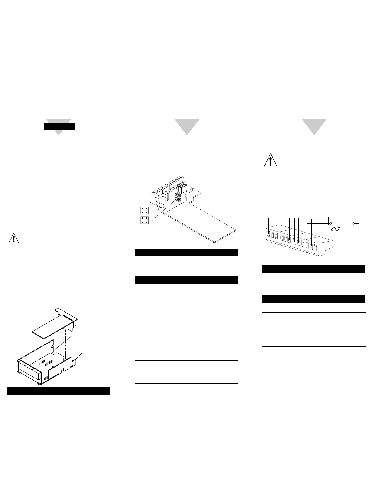
BOARD INSTALLATION:
To install optional Relay Output printed circuit board:
1.
Refer to “Reveal the Main Board” in Main Operator’s
Manual Section 5.2, Disassembly.
2.
Using figure below as a reference, insert relay option
board(s) into J10 connector on the main board.
WARNING: To avoid electrical shock be sure
to disconnect the unit from its power supply.
After you have opened the meter you are
ready to install option card.
To install:
1. Hold relay board with components facing the main
board.
2. Position the P10 connector to mate with the J10
connector on the main board (at rear of unit).
3.
Push the board downward, guiding relay board
edges through the rear panel guides until it rests on
the upper rear panel and the main board.
Figure 1 Option Board Installation
4 RELAY OUTPUT BD
SIGNAL INPUT BD
AC POWER BD
P10
J10
Start Here
JUMPER CONFIGURATION:
The figure below shows the locations of the 4 Relay
Output Board jumpers S1 and S2, the P10 socket
connecting the board to the Main Board, and the
output plugs P6, P7, P18A and P18B.
Press This Button
Figure 2 4 Relay Board Jumpers and Plugs
The table below shows which jumpers are assigned
to each relay. Defaults have asterisks.
re 4 Relay Output Board Wiring Connections
Table 1 4 Relay Board Jumpers
S1 S2 FUNCTION
Assigns SP1 to Relay 1 (P6)
A, C* A, C* Assigns SP2 to Relay 2 (P7)
Assigns SP3 to Relay 3 (P18A)
Assigns SP4 to Relay 4 (P18B)
Assigns SP1 to Relay 3 (P18A)
B, D A, C Assigns SP2 to Relay 2 (P7)
Assigns SP3 to Relay 1 ( P6)
Assigns SP4 to Relay 4 (P18B)
Assigns SP1 to Relay 3 (P18A)
B, D B, D Assigns SP2 to Relay 4 (P18B)
Assigns SP3 to Relay 1 ( P6)
Assigns SP4 to Relay 2 ( P7)
Assigns SP1 to Relay 1 (P6)
A, C B, D Assigns SP2 to Relay 4 (P18B)
Assigns SP3 to Relay 3 (P18A)
Assigns SP4 to Relay 2 (P7)
A
B
C
D
S1
S2
B
D
A
C
S
1
S
2
P18B
P18A
P7
P6
P10
2
WIRING CONNECTIONS:
WARNING: Do not connect ac power
meter until you have completed all input
and output connections. Failure to do so
may result in injury! This device must only
be installed electrically by a specially
trained electrician with corresponding
qualifications.
Press This Button
Figure 3 4 Relay Output Board W iring Connections
Table 2 Pin Assignments for the P6, P7 and P18
CONNECTOR PIN FUNCTION
P6 1 NO1 (Normally Open)
(Relay 1 Connection) 2 Common 1
3 NC1 (Normally Closed)
P7 1 NO2 (Normally Open)
(Relay 2 Connection) 2 Common 2
3 NC2 (Normally Closed)
P18A 1 NO3 (Normally Open)
(Relay 3 Connection) 2 Common 3
3 NC3 (Normally Closed)
P18B 1 NO4 (Normally Open)
(Relay 4 Connection) 2 Common 4
3 NC4 (Normally Closed)
1
2
3
1
2
P18A
P18B
3
}
}
Relay 3
Relay 4
N.O.3
COM3
N.C.3
N.O.4
COM4
N.C.4
EXTERNAL LOAD
N
L
FUSE
N.O.4
COM4
1
2
3
1
2
P6
P7
3
}
}
Relay 1
Relay 2
N.O.1
COM1
N.C.1
N.O.2
COM2
N.C.2
3
 Loading...