

Page 1
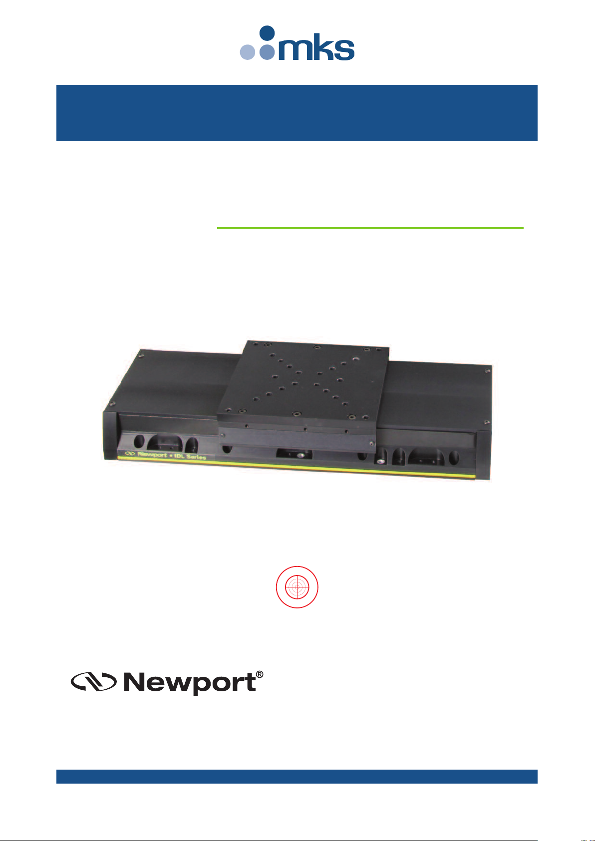
IDL165-LM Series
G
U
A
R
A
N
T
E
E
D
S
P
E
C
I
F
I
C
A
T
I
O
N
S
Long Travel
Industrial Linear Stages
USER’S MANUAL
Page 2
IDL165-LM Series Long Travel Industrial Linear Stages
Newport Corporation warrants this product to be free from defects in
material and workmanship for a period of 1 year from the date of
shipment. If found to be defective during the warranty period, the product
will either be repaired or replaced at Newport’s discretion.
To exercise this warranty, write or call your local Newport representative,
or contact Newport headquarters in Irvine, California. You will be given
prompt assistance and return instructions. Send the instrument,
transportation prepaid, to the indicated service facility. Repairs will be
made and the instrument returned, transportation prepaid. Repaired
products are warranted for the balance of the original warranty period, or
at least 90 days.
Limitation of Warranty
This warranty does not apply to defects resulting from modification or
misuse of any product or part.
This warranty is in lieu of all other warranties, expressed or implied,
including any implied warranty of merchantability or fitness for a
particular use. Newport Corporation shall not be liable for any indirect,
special, or consequential damages.
by Newport Corporation, Irvine, CA. All rights reserved.
Original instructions.
No part of this document may be reproduced or copied without the prior
written approval of Newport Corporation. This document is provided for
inf or mation o nly, and pro duct spe cificati ons are s ub ject to ch ange witho ut
CAUTION
Warranty does not apply to damages resulting from:
• Incorrect usage:
– Load on the stage greater than maximum specified load.
– Carriage speed higher than specified speed.
–Improper grounding.
¬ Connectors must be properly secured.
¬ When the load on the stage represents an electrical risk, it must
be connected to ground.
– Excessive or improper cantilever loads.
• Modification of the stage or any part thereof.
CAUTION
Please return equipment in
the original (or equivalent)
packing.
You will be responsible for
damage incurred from
inadequate packaging if the
original packaging is not
used.
Warranty
EDH0360En1022 — 12/18 ii
© 2018
Page 3

IDL165-LM Series Long Travel Industrial Linear Stages
Table of Contents
Warranty .................................................................................................................ii
Declaration of Incorporation ................................................................................v
Definitions and Symbols.......................................................................................vi
Warnings ...............................................................................................................vii
Caution ...................................................................................................................ix
1.0 — Introduction.................................................................................1
2.0 — Description ...................................................................................2
2.1 Design Details ............................................................................................2
3.0 — Characteristics............................................................................3
3.1 Definitions..................................................................................................3
3.2 Mechanical Specifications .......................................................................4
3.3 Hard Stop: Speed Limitation Versus Load .............................................4
3.4 Load Characteristics and Stiffness .........................................................5
3.5 Stage Weight ..............................................................................................5
4.0 — Drive and Motor.........................................................................6
4.1 Motor characteristics (Direct Drive Brushless Motor)........................6
4.2 Command Signals......................................................................................6
4.3 Sensor Positions........................................................................................7
4.4 Position Feedback Signals........................................................................7
4.5 General Wiring...........................................................................................8
4.6 Pinouts........................................................................................................8
Hall Effect Sensor (SUB-D15F Connector) ..............................................8
Encoder (SUB-D15M Connector).............................................................8
Encoder (SUB-D26HDM Connector on E5820A Adapter) .....................9
Motor (DB9W4M Connector)...................................................................9
4.7 IDL165-LM Cable Wirings .........................................................................9
4.8 Air Tube....................................................................................................10
5.0 — Stage Installation.....................................................................11
5.1 Unpacking ................................................................................................11
5.2 Setting Up.................................................................................................11
5.3 Mounting Conditions ..............................................................................13
5.4 Air Blowing...............................................................................................13
iii EDH0360En1022 — 12/18
Page 4

IDL165-LM Series Long Travel Industrial Linear Stages
6.0 — Connection to Newport Controllers ..............................14
6.1 Warnings on Controllers ........................................................................14
6.2 Connection...............................................................................................15
6.3 Cables .......................................................................................................15
6.4 Adapter for the XPS-D Newport Controller..........................................15
7.0 — Connection to Non-Newport Controllers ....................16
8.0 — Dimensions.................................................................................17
9.0 — Maintenance ..............................................................................17
9.1 Maintenance ............................................................................................17
9.2 Repair .......................................................................................................18
9.3 Calibration ...............................................................................................18
Service Form .........................................................................................................19
EDH0360En1022 — 12/18 iv
Page 5

IDL165-LM Series Long Travel Industrial Linear Stages
T
H
– –§––ei–
–HUMmHi
DHQ
H
E MAN
U
ereby dec
l
y De
y Fu
n
y M
o
the technic
Mr
H
MIC
F-45
complies
w
1.3.7 and 1
complies
w
was desig
n
lectro-mag
n
ntended use
complies
w
was desig
n
y E
N
requ
i
y N
F
requ
i
y N
F
risk
r
ereby decl
a
ndertakes t
ember Sta
t
anufacturi
n
ereby decl
a
ncorporated
one in Be
a
ervé LE C
O
uality Dir
e
F
ACTUR
E
Me9
F
ares that t
h
scription : "
I
ction: Lon
g
del: IDL16
al file of w
h
ervé LE C
O
RO-CONT
R
340 Beaune
ith the appl
i
.1.5 for whi
c
ith all the r
e
ed and built
etic compat
i
of its comp
o
ith all the r
e
ed and built
ISO 60204
-
rements »
EN 61326-
rements –
P
EN ISO 12
eduction »
res that the
o present up
es for at lea
s
g site in Be
a
res that this
has been de
une La R
o
INTE
ctor
O
R
,
I
CRO-CO
N
stablished i
n
rue du Boi
s
-91055 Evr
y
e partly co
m
DL165-LM
Travel Ind
u
5-200LM.
ich was co
m
INTE, Qua
l
OLE Spect
r
La Rolande
cable essen
t
h a residua
l
levant prov
i
in accordan
c
bility, appl
y
nents
levant prov
i
in accordan
c
1 « Safety
o
1:2013 « El
e
art 1: Gener
a
100:2010 «
S
elevant tec
h
on request t
h
t 10 years f
o
une-La-Ro
l
equipment
m
clared in co
n
lande on 2
2
D
I
F PARTL
of the D
i
T
ROLE S
p
France,
Sauvage
pleted ma
c
strial Linea
r
piled by:
ity Director
,
a-Physics,
Z
France
ial require
m
risk exists
w
sions of the
e with the r
ing good en
sions of the
e with the
f
f machiner
y
ctrical equi
p
l requirem
e
afety of m
a
nical docu
m
e relevant t
e
llowing thi
s
ande (45, F
r
ust not be
p
formity wit
h
ORIGI
May 201
7
ECLAR
A
NCORP
O
Y COMPL
following
A
rective 2006
/
e
ctra-Physi
c
hinery:
Stages.
one Industr
i
ents include
hen puttin
g
Directive 2
0
elevant pro
v
gineering p
r
Directive 2
0
ollowing ha
r
– Electrica
l
ment for
m
nts »
chinery – G
e
entation de
s
chnical doc
date; the d
o
ance).
ut into serv
i
the provis
i
NAL DECLA
R
TION OF
RATION
TED MA
C
nnex II-1B
42/EC on ma
s
,
elle - B.P.2
9
in Annex
I
the equipm
e
14/35/EU “
L
isions of th
e
actices and
r
11/65/EU r
e
monised st
a
equipment
o
easurement,
neral princ
i
cribed in A
n
mentation
t
cumentatio
n
ce until the
ons of this
D
ATION
HINERY
hinery
of the Dire
c
nt into serv
i
ow Voltag
e
Directive 2
0
especting th
lating to Ro
H
ndards:
f machines
control and
les for desi
nex VII, pa
r
o the comp
e
will be ava
final machi
n
irective.
N° of
C
IDL
1
Numbe
tive 2006/4
2
ice
”
14/30/EU
r
e informati
o
HS2.
– Part 1 Ge
n
laboratory
u
gn – Risk a
s
t B has bee
n
tent authori
t
ilable on ou
r
ery into wh
i
DI1-EN re
v
ertificate
65-LM
r of pages
1
/EC except
elating to
n on the
eral
se – EMC
sessment an
compiled.
ies of the
ch it is to
be
:A
d
Declaration of Incorporation
v EDH0360En1022 — 12/18
Page 6
IDL165-LM Series Long Travel Industrial Linear Stages
The following terms and symbols are used in this documentation and also
appear on the product where safety-related issues occur.
General Warning or Caution
The exclamation symbol may appear in warning and caution tables in this
document. This symbol designates an area where personal injury or
damage to the equipment is possible.
The following are definitions of the Warnings, Cautions and Notes that may
be used in this manual to call attention to important information regarding
personal safety, safety and preservation of the equipment, or important
tips.
WA RN IN G
Warning indicates a potentially dangerous situation which can result in
bodily harm or death.
CAUTION
Caution indicates a potentially hazardous situation which can result in
damage to product or equipment.
NOTE
Note indicates additional information that must be considered by the
user or operator.
Warnings and Cautions
ATTENTION
This stage is a Class A device. In a residential environment, this device
can cause electromagnetic interference. In this case, suitable measures
must be taken by the user.
Definitions and Symbols
EDH0360En1022 — 12/18 vi
Page 7
IDL165-LM Series Long Travel Industrial Linear Stages
WA RN IN G
The motion of objects of all types carries potential risks for operators.
Ensure the protection of operators by prohibiting access to the dangerous
area and by informing the personnel of the potential risks involved.
ARNING
W
When the IDL165-LM stage is installed or combined with other instruments
in a machine, additional testing to directive 2006/42/EC may be required.
t is the responsibility of the end-user or integrator to perform a risk-
I
analysis and the necessary tests to conform to the EC directives.
Newport is not liable for damages caused by not executing this
responsibility.
Warnings
Improper use of an IDL165-LM can cause material damage, shock, injury,
or death. Read and understand this User's Manual before operating an
IDL165-LM stage.
If the IDL165-LM is used in a condition not specified by Newport, the
safety features provided by the stage can be impaired.
WARNING
Very fast moving parts of the stage or any attachments can cause
crushing or shearing injuries. All personnel must remain clear of any
moving parts.
WARNING
The connection of electrical devices must meet safety and electrical
standards. Grounding methods indicated in this manual must be
applied.
WARNING
Due to the nature of this stage, the installation, use and maintenance of
this stage must be performed by trained personnel who are familiar
with safety regulations that are applicable to this product.
vii EDH0360En1022 — 12/18
Page 8
IDL165-LM Series Long Travel Industrial Linear Stages
WA RN IN G
Do not use this stage when its motor is emitting smoke or is unusually
hot to the touch or is emitting any unusual odor or noise or is in any
other abnormal state.
Stop using the stage immediately, switch off the motor power and then
disconnect the electronics power supply.
After checking that smoke is no longer being emitted contact your
Newport service facility and request repairs. Never attempt to repair the
stage yourself as this can be dangerous.
WA RN IN G
Make sure that this stage is not exposed to moisture and that liquid does
not get into the stage.
Nevertheless, if any liquid has entered the stage, switch off the motor
power and then disconnect the electronics from power supply.
Contact your Newport service facility and request repairs.
WA RN IN G
Do not insert or drop objects into this stage, this may cause an electric
shock, or lock the drive.
Do not use this stage if any foreign objects have entered the stage.
Switch off the motor power and then disconnect the electronics power
supply.
Contact your Newport service facility for repairs.
WA RN IN G
Do not place this stage in unstable locations such as on a wobbly table or
sloping surface, where it may fall or tip over and cause injury.
If this stage has been dropped or the case has been damaged, switch off
the motor power and then disconnect the electronics power supply.
Contact your Newport service facility and request repairs.
WA RN IN G
Do not attempt to modify this stage; this may cause an electric shock or
downgrade its performance.
WA RN IN G
Do not exceed the usable depth indicated on the mounting holes (see
section “Dimensions”). Longer screws can damage the mechanics or
cause a short-circuit.
W
ARNING
The magnetic channel included in this device has the potential to disrupt
pacemakers. Consequently, it is r ecommended that individuals maintain a
d
istance of 1 meter or more from the stage as a precautionary measure.
WARNING
Do not exceed speed and load limitations as specified in this manual.
EDH0360En1022 — 12/18 viii
Page 9
IDL165-LM Series Long Travel Industrial Linear Stages
C
AUTION
Do not place this stage in a hostile environment such as X-Rays, hard
UV,… or in any vacuum environment.
CAUTION
Do not place this stage in a location affected by dust, oil fumes, steam or
high humidity. This may cause an electric shock.
CAUTION
Do not leave this stage in places subject to extremely high temperatures
or low temperatures. This may cause an electric shock.
• Operating temperature: +10 to +35 °C
• Storage/Operating altitude: 1000 m
• Storage/Operating humidity: 85%
• Storage temperature: -10 to +40 °C (in its original packaging)
CAUTION
Do not move this stage if its motor power is on.
Make sure that the cable to the electronics is disconnected before
moving the stage. Failure to do so may damage the cable and cause an
electrical shock.
CAUTION
Be careful that the stage is not bumped when it is being carried. This
may cause it to malfunction.
CAUTION
When handling this stage, always unplug the equipment from the power
source for safety.
CAUTION
When the carriage is in its end-of-run position, it is strongly recommended
not to go beyond this point as this may damage the stage mechanism.
CAUTION
Contact your Newport service facility to request cleaning and
specification control every year.
Caution
ix EDH0360En1022 — 12/18
Page 10

IDL165-LM Series Long Travel Industrial Linear Stages
EDH0360En1022 — 12/18 x
Page 11

IDL165-LM Series Long Travel Industrial Linear Stages
Long Travel Industrial Linear Stages
IDL165-LM Series
1.0 —Introduction
This manual provides operating instructions for the IDL165-LM stage that
you have purchased.
RECOMMENDATION
Read and understand this user's manual before operating an IDL165-LM
stage.
Inside this manual you will find useful information and technical
references. It is recommended the user download all support
documentation from the IDL165-LM page of the Newport website for
reference.
IDL165-200LM Stage.
RECOMMENDATION
We recommend you carefully read the chapter “Connection to
electronics” before using the IDL165-LM stage.
1 EDH0360En1022 — 12/18
Page 12

IDL165-LM Series Long Travel Industrial Linear Stages
2.0 —Description
The IDL165-LM Series of Industrial-grade linear stages is another robust
amily of high quality Newport products, designed for higher throughput
f
and reliability. This series is designed specifically for laser micromachining applications that require high precision, down to 250 nm.
Additional features for use in industrial environments include a hard top
cover, flexible side bands and air purge.
tarting with an FEA-optimized body, recirculating bearings, high
S
efficiency linear motor and a direct read linear encoder, all components
were selected to enable the high precision and dynamic performance
expected of high throughput and demanding applications. Other features
include positive and negative end of runs to prevent overtravel, energy
absorbers for unintended scenarios and an origin switch that can be used
as a reference for absolute positioning.
Four sizes are offered to address a wide range of loads and travel.
2.1 Design Details
Base Material Aluminum
Bearings Recirculating caged ball bearings
Drive Mechanism Ironless linear motor
Feedback Linear steel scale with 20 µm pitch
Limit Switches Positive and Negative End-Of-Run -5 V
Origin Optical at center of travel
Cable 4.5 m Connectorized, optional cable management
EDH0360En1022 — 12/18 2
Page 13

IDL165-LM Series Long Travel Industrial Linear Stages
Specifications of our products are established in reference to ISO 230
standard part II “Determination of accuracy and repeatability of
positioning numerically controlled axes”.
T
his standard gives the definition of position uncertainty which depends
on the 3 following parameters:
Absolute Accuracy
Difference between ideal position and real position.
Accuracy
Difference between ideal position and real position after the compensation
of linear errors.
Linear errors include: cosine errors, inaccuracy of screw or linear scale
pitch, angular deviation at the measuring point (Abbe error) and thermal
expansion effects. All Newport motion electronics can compensate for
linear errors.
The relation between absolute accuracy and on-axis accuracy is as follows:
Absolute Accuracy = Accuracy + Correction Factor
x Travel
Repeatability
Ability of a system to achieve a commanded position over many attempts.
Reversal Value (Hysteresis)
Difference between actual position values obtained for a given target
position when approached from opposite directions.
Minimum Incremental Motion (MIM or Sensitivity)
The smallest increment of motion a device is capable of delivering
consistently and reliably.
Resolution
The smallest increment that a motion device can theoretically move
and/or detect. Resolution is not achievable, whereas MIM, is the real
output of a motion system.
Yaw, Pitch
Rotation of carriage around the Z axis (Yaw) or Y axis (Pitch), when it
moves.
The testing of accuracy, repeatability, and reversal error are made
systematically with test equipment in controlled environment (20±1°C).
A linear cycle with 21 data points on the travel and 4 cycles in each
direction gives a total of 168 points.
Guaranteed and Typical Specifications
Guaranteed maximum performance values are verified per Newport's A167
metrology test procedure. For more information, please consult the
metrology tutorial section in the Newport catalog or at www.newport.com
3.0 —Characteristics
3.1 Definitions
3 EDH0360En1022 — 12/18
Page 14

IDL165-LM Series Long Travel Industrial Linear Stages
G
U
A
R
A
N
T
E
E
D
S
P
E
C
I
F
I
C
A
T
I
O
N
S
Load on Carriage (kg)
Maximum Speed for Hard Stoppers
600
2000
1800
1600
1400
1200
1000
800
0 5010 20 30 40
Speed (mm/s)
3.2 Mechanical Specifications
IDL165-200LM
Travel Range (mm) 200
Minimum Incremental Motion
Bi-directional Repeatability
Typical (Guaranteed)
(1)
Accuracy
(µm)
Typical (Guaranteed)
Origin Repeatability (µm) ±0.1
Maximum Speed (mm/s) 2,000
Max. Acceleration (m/s2) 30
Moving Mass (kg) 2.25
(3)
Pitch
, Guaranteed (µrad) (±20)
(3)
Yaw
, Guaranteed (µrad) (±20)
Straightness/Flatness (µm) ±4.5/±4.5
Normal Load Capacity [Cz] (N) 450
Axial Load, Continuous, [±Cx] (N) 57
1)
For the definition of Typical and Guaranteed specifications see “Motion Basics Terminology & Standards”
Tutorial at www.newport.com
2)
Driver dependent.
3)
To obtain arcsec units, divide µrad value by 4.8.
(2)
(µm) 0.050
(1)
(µm)
±0.10 (±0.25)
0.8 (±2.0)
NOTE
The following specifications are controller/drive dependent. Refer to the
IDL165-LM Series page on www.newport.com for specifications
achievable with specific Newport controller/drive combination.
• MIM
• Accuracy
• Repeatability
• Max Speed
• Max Acceleration
3.3 Hard Stop: Speed Limitation Versus Load
IDL165-LM stages use electrical end-of-run and elastomer hard stops to
stop the carriage as smoothly as possible past the end-of-runs. The
overtravel allowed by the hard stops is 0.23 in. (5.8 mm).
When the stage is used with a controller supplied by Newport, the factory
settings of the "software limits" prohibit any commanded motion beyond
this travel range.
Nevertheless, for safety reasons, follow the recommendations
above to minimize risk of mechanical damage, in case of failure
or incorrect adjustment of parameters.
EDH0360En1022 — 12/18 4
The maximum speed of the stage must be limited so that the
hard stops will always stop the carriage in 0.23 in. (5.8 mm) or
less, to avoid any shock between the carriage and stage body.
The graph at left, provides stage speed as a function of applied
load. This curve defines allowed operating conditions to stop
within the 0.23 in. (5.8 mm) over-travel allowed by the hard
stops. To stop within this distance, the user must maintain
speed and load within this tolerance. This graph assumes
correct wiring of the electrical end of runs will cut motor power
before contact with the hard stop.
Page 15

IDL165-LM Series Long Travel Industrial Linear Stages
Z
Y
Q
D
C
z
X
kα
y
k
α
z
k
α
x
±
C
x
Off-Center Load (N)
0
Off-Center Load Along X or Z Axis
Off-Center Load Along Y Axis
50 100 150 200 250 300 350 400 450
Cantilever Distance “D” (mm)
0
140
1
20
100
80
6
0
40
20
160
3.4 Load Characteristics and Stiffness
Normal Load Capacity (Cz)
aximum load a stage can move while maintaining specifications.
M
Cz, Normal center load capacity on bearings 450 N
±Cx, Axial Load, Continuous 57 N
kax, Angular stiffness (Roll) 0.3 µrad/Nm
kay, Angular stiffness (Pitch) 0.4 µrad/Nm
kaz, Angular stiffness (Yaw) 0.4 µrad/Nm
Max. values for the normal center load (Cz) and the off-center load (Q) are
given in the graphs below.
3.5 Stage Weight
The stage weight indicated below does not include the cables.
Weight [lb (kg)]
IDL165-200LM 22.0 (10)
5 EDH0360En1022 — 12/18
Page 16

IDL165-LM Series Long Travel Industrial Linear Stages
U-V
-2
0
Ha
Hb
Hc
-0.5
-1
-1.5
0.5
1
1.5
2
Amplitude
U-WV-W
Induced Voltages Coil Moving
Motion Direction +
Direction +
4.0 —Drive and Motor
4.1 Motor characteristics (Direct Drive Brushless Motor)
Continuous force, coil @ 100 °C 57 N
Continuous force, 3-bar Air Cooling, coil @ 100 °C 68 N
Peak force 289 N
Motor constant 69 N2/W
Continuous power 49.7 W
Peak power 796 W
Electrical cycle 60 mm
Max. bus voltage 330 V
Max. coil temperature 125 °C
Thermal dissipation constant 1.0 W/°C
Continuous current 3.6 Arms
Continuous current, AC 4.3 Arms
Peak current 18.4 Arms
Force constant 15.7 N/Arms
Back-emf constant 12.8 V/m/s
Inductance 1.57 mH
Thermal resistance @ 25 °C 2.35 Ω
Electrical time constant 0.67 ms
CAUTION
High RMS current will generate motor heating which will degrade
characteristics of the stage, such as repeatability, accuracy, etc…
4.2 Command Signals
NOTE
The values above indicate voltage induced by energized coil of one
phase on next phase coil. A positive value for U-V would indicate a
higher voltage on U relative to V.
EDH0360En1022 — 12/18 6
Page 17

IDL165-LM Series Long Travel Industrial Linear Stages
– End-of-Run Limit
+ End-of-Run Limit
Index Pulse
Index Pulse
Motion Direction +Direction –
1
.97
(50)
.
04 (1).04 (1)
Negative
Software Limit
S
tage Travel Range
Positive
Software Limit
Home Position
(
Origin)
Dimensions in inches
(and millimeters)
Direction +
X
Low
High
Low
High
Low
High
Low
High
Encoder
Phase A
Encoder
Phase A
Encoder
Phase B
Encoder
Phase B
1234
Encoder Feedback Signal Position
Motion Direction +Direction –
Direction +
4.3 Sensor Positions
X Values – Hard – End-of-Run Home + End-of-Run + Hard
[in. (mm)] Stop Limit Position Limit Stop
IDL165-200LM
4.45
(113
0
-0.23
0
) (114
-5.8
±0.02
4.49
8.46
±0.5
) (215±1) (316
±0.04
12.44
±0.02
±0.5
) (317
12.48
+0.23
0
5.8
+
)
0
4.4 Position Feedback Signals
Signal description/Voltage/Wiring Heidenhain standard 1 Vpp
Reference mark position see drawing "Sensor Positions"
Resolution Scale pitch 20 µm
Maximum speed 8 m/s
7 EDH0360En1022 — 12/18
Page 18

IDL165-LM Series Long Travel Industrial Linear Stages
M
otor
E
ncoder
I
DL-LM Controller
A
/A
B
/B
I
/
I
5
V
0 V
U
V
W
Gnd
T
+
T
-
H
a
H
b
H
c
U
V
W
Gnd
T
+
T
-
A
/A
B
/B
I
/
I
5
V
0 V
Ha
H
b
H
c
i
2c Data
i2c Clock
ZM
FC+
F
C-
F
ault
I
nhibit
U
command
Gnd
V
command
Gnd
Driver
Gnd
V
command
G
nd
U
command
Inhibit
Fault
FCFC+
Z
M
i
2c Clock
i2c Data
8
159
1
8
159
1
4.5 General Wiring
4.6 Pinouts
The pinout diagrams for IDL165-LM stage connectors are shown below.
4.6.1 Hall Effect Sensor (SUB-D15F Connector)
4.6.2 Encoder (SUB-D15M Connector)
1 +5 V
2 N.C.
3 N.C.
4 N.C.
5 N.C.
6 Ground
7 Ha
8 Hb
1 Encoder Phase B
2 Ground
3 Encoder Phase A
4 +5 V Encoder
5 N.C.
6 – End-of-Run
7 Index Pulse /I
8 + End-of-Run
9 N.C.
10 N.C.
11 N.C.
12 N.C.
13 N.C.
14 Hc
15 N.C.
9 Encoder Phase /B
10 Ground
11 Encoder Phase /A
12 +5 V
13 N.C.
14 Index Pulse I
15 N.C.
EDH0360En1022 — 12/18 8
Page 19

IDL165-LM Series Long Travel Industrial Linear Stages
9
1
0 18
2
619
1
A
4 A3 A2 A1
5
1
SUB-D15F
Connector
7
8
14
1
6
Connector
Cap
IDL-LM
Ha
Hb
Hc
+5 V
Ground
Hall Effect
Sensor
SUB-D15M
Connector
3
11
1
9
14
7
4
6
8
2
12
10
Connector
Cap
IDL-LM
Encoder Phase A
Encoder Phase /A
Encoder Phase B
Encoder Phase /B
Index Pulse I
Index Pulse /I
+5 V
LimitLimit+
Ground
+5 V
Ground
Encoder
4.6.3 Encoder (SUB-D26HDM Connector on E5820A Adapter)
The E5820A adapter allows to connect the encoder cable with our XPS-D
ontroller.
c
4.6.4 Motor (DB9W4M Connector)
1 +5 V
2 N.C.
3 N.C.
4 Encoder Phase B
5 – End-of-Run
6 Encoder Phase A
7 Ground
8 Index Pulse I
9 N.C.
10 N.C.
11 N.C.
12 N.C.
13 Encoder Phase /B
14 + End-of-Run
15 Encoder Phase /A
16 N.C.
17 Index Pulse /I
18 +5 V
19 N.C.
20 Ground
21 N.C.
22 N.C.
23 N.C.
24 N.C.
26 N.C.
26 N.C.
A1 Phase U Motor
A2 Phase V Motor
A3 Phase W Motor
A4 Ground + Shield
1 T+
2 T-
3 N.C.
4 N.C.
5 N.C.
9 EDH0360En1022 — 12/18
4.7 IDL165-LM Cable Wirings
IDL165-LM stages are delivered equipped with the three cables required
for operation. The wiring diagrams and connectors for these cables are
provided below. When operating with non-Newport controllers, it is
recommended to adhere to the wiring conventions presented here.
Hall Effect Sensor Cable
• Cable: Ø 3.3 mm
• Min. dynamic bending radius: 33 mm
Encoder Cable
• Cable: Ø 4.25 mm
• Min. dynamic bending radius: 20 mm
Page 20

IDL165-LM Series Long Travel Industrial Linear Stages
DB9W4M
Connector
A1
A2
A3
A4
1
2
Connector
Cap
IDL-LM
Phase U Motor
Phase V Motor
Phase W Motor
Ground + Shield
TT+
Motor
A
1
A
2
A
3
A4
1
2
P
hase U Motor
P
hase V Motor
P
hase W Motor
Ground + Shield
TT+
Self
Customer
Electronics
Yellow
Grey
Orange
Blue
Green
Red
M1
M2
M3
PE
AIR BLOWING TUBE
LEGRIS 3606.06.00 CONNECTOR
MOTOR CABLE
DB9W4M CONNECTOR
ENCODER CABLE
SUB-D15M CONNECTOR
HALL EFFECT SENSOR CABLE
SUB-D15F CONNECTOR
Motor Cable
Cable: Ø 6 mm
•
Min. dynamic bending radius: 60 mm
•
NOTE
A filter is supplied with each IDL165-LM stage. It can be
used with an electronics other than the Newport XS-EDBL
controller if the level of the noise is considered too high.
4.8 Air Tube
• Tube: ø.24 in. (6 mm) with Legris connector ref. 3606.06.00
• Min. dynamic bending radius: 27 mm
EDH0360En1022 — 12/18 10
Page 21

IDL165-LM Series Long Travel Industrial Linear Stages
1 HANDLE
ON EACH END
1
LOCKING BRACKET
5.0 —Stage Installation
5.1 Unpacking
The IDL165-LM stage will be delivered in packaging that is designed for
afe transport. Attached to the body of the stage are handles for safe
s
removal from packaging. It is recommended to carefully lift and move the
stage from packaging using these handles.
The stage will come with a control report that indicates performance of
your stage within guaranteed specifications. These measurements were
taken in a controlled environment and flat mounting conditions.
5.2 Setting Up
The IDL165-LM stage is equipped with 2 handles and 1 bracket to lock the
carriage during transportation. To safely unpack the stage, follow the
instructions below
Remove handling and locking
systems before using.
NOTE
An Allen key is supplied for CHc M4 screws.
CAUTION
11 EDH0360En1022 — 12/18
Page 22

IDL165-LM Series Long Travel Industrial Linear Stages
① Unscrew with the supplied Allen key, 2 CHc M4 screws from the
shipping bracket on the body of the stage.
② Unscrew with the supplied Allen key, 2 CHc M4 screws from the
shipping bracket attached to the carriage.
③ Remove the shipping bracket.
④ Unscrew with the supplied Allen key, 2 CHc M4 screws from the 2
handles.
EDH0360En1022 — 12/18 12
Page 23

IDL165-LM Series Long Travel Industrial Linear Stages
5.3 Mounting Conditions
IDL165-LM stages feature an eight-point mounting pattern which is ideal for
on-flat surfaces. However it is recommended for all IDL165-LM stages that
n
the following mounting conditions be adhered to for best performance and
security.
Installation Considerations
<400 mm Travel <800 mm Travel
Mounting surface flatness 10 µm 15 µm
Payload surface flatness 20 µm 20 µm
Mounting Screw torque M6: 7.0 Nm
M5: 4.1 Nm
M4: 2.1 Nm
5.4 Air Blowing
When used in dusty environment (dust, debris…), the stage can be
protected by connecting an air source to the air tube plug (see sections
4.8 & 8.0 of this manual). This will prevent pollution from coming in by
slightly increasing stage internal pressure. Such air injection can also be
used to improve motor heat dissipation and limit temperature increase.
Here are the required characteristics for the air source:
• Pressure: 6.0 bars
• Particle size: 5 µm
• Particle density: 5 mg/m
3
• Dew point: -20 °C
• Gas Oil ratio: 1 mg/m
3
13 EDH0360En1022 — 12/18
Page 24

IDL165-LM Series Long Travel Industrial Linear Stages
Controllers are intended for use by qualified personnel who recognize
shock hazards and are familiar with safety precautions required to avoid
p
ossible injury. Read the controller user’s manual carefully before
operating the instrument and pay attention to all written warnings and
cautions.
WA RN IN G
Disconnect the power plug under the following circumstances:
• If the power cord or any attached cables are frayed or damaged in
any way.
• If the power plug is damaged in any way.
• If the unit is exposed to rain, excessive moisture, or liquids are spilled
on the unit.
• If the unit has been dropped or the case is damaged.
• If you suspect service or repair is required.
• Whenever you clean the electronics unit.
CAUTION
To protect the unit from damage, be sure to:
• Keep all air vents free of dirt and dust.
• Keep all liquids away from the unit.
• Do not expose the unit to excessive moisture (85% humidity).
• Read this manual before using the unit for the first time.
WA RN IN G
All attachment plug receptacles in the vicinity of this unit are to be of
the grounding type and properly polarized.
Contact your electrician to check your receptacles.
WA RN IN G
This product is equipped with a 3-wire grounding type plug.
Any interruption of the grounding connection can create an electric
shock hazard.
If you are unable to insert the plug into your wall plug receptacle,
contact your electrician to perform the necessary alterations to ensure
that the green (green-yellow) wire is attached to earth ground.
WA RN IN G
This product operates with voltages that can be lethal.
Pushing objects of any kind into cabinet slots or holes, or spilling any
liquid on the product, may touch hazardous voltage points or short out
parts.
6.0 —Connection to Newport Controllers
6.1 Warnings on Controllers
EDH0360En1022 — 12/18 14
Page 25

IDL165-LM Series Long Travel Industrial Linear Stages
6.2 Connection
There is a label on every stage indicating its part and serial numbers.
ARNING
W
Always turn the controller's power OFF before connecting a stage.
NOTE
Supplied cables are compatible with Newport controllers. For more
information, please contact your sales representative.
6.3 Cables
IDL165-LM stages are delivered with three 4.5-meter cables that can be
directly connected to the Newport controller.
WARNING
IDL165-LM Series translation stages can only operate with cable lengths
of 4.5 m or less.
WARNING
These cables are shielded. For correct operation, make sure to lock
connectors (ground continuity provided by cables).
WARNING
Keep the cables at a safe distance from other electrical cables in your
environment to avoid potential cross talk.
6.4 Adapter for the XPS-D Newport Controller
The E5820A adapter supplied with each IDL165-LM stage, allows the
connection of the encoder cable with our XPS-D controller.
15 EDH0360En1022 — 12/18
Page 26

IDL165-LM Series Long Travel Industrial Linear Stages
7.0 —Connection to Non-Newport Controllers
Newport stages can be operated with Non-Newport controllers. However,
nder such operating conditions Newport makes no guarantee regarding
u
achievable specifications. To aid Newport customers using non-Newport
Controllers with IDL165-LM Series stages, wiring conventions and motor
characteristics are provided. It should be noted, damage caused by
improper configuration or operation while in use with non-Newport
ontrollers is not covered by the warranty.
c
Please refer to the Design Details and Specifications for more information
to help configure the stage with your controller. Newport also provides a
tech note on configuring third party stages with Newport controllers in the
IDL165-LM website, which may be useful as a reference.
WARNING
Newport is not responsible for malfunction or damage of IDL165-LM
stages when used with non-Newport controllers.
It is the customer’s responsibility to modify the cable and take care of
sensor signal connections, when using the stage with non-Newport
controllers.
WARNING
• Maximum peak voltage: 330 Vpeak
• Maximum rms current: 3.6 Arms without air cooling
4.3 Arms with 3-bar air cooling
EDH0360En1022 — 12/18 16
Page 27

IDL165-LM Series Long Travel Industrial Linear Stages
2.76
(70)
.
39 (10)
6
.50
(
165)
6.85 (174)
BOTH SIDES:
3 HOLES M4 THD, DEPTH: .31 (8)
2.54
(64.5)
.39
(10)
1.75
(44.5)
A
(1)
AT MAX. TRAVEL
A
(1)
AT MAX. TRAVEL
5
.91 (150)
L
3.94
(100)
B B
3.94
(100)
M
ODEL TRAVEL L A
(1)
n1 B n2
I
DL165-200LM
7.87 16.93 7.67
8
5.71
6
(200) (430) (194.8) (145)
1)
INCLUDING OVER-TRAVEL ALLOWED BY THE HARD STOP.
MODEL SHOWN: IDL165-200LM
DIMENSIONS IN INCHES (AND MILLIMETERS)
.67 (17) .31 (8)
5.94
(151)
5.91
(150)
1.57
(40)
S
QR 2.95
(
75)
SQR 3.94
(100)
SQR 5.91
(150)
.
55
(
14)
n2 x 2 HOLES
M4 THD
DEPTH: .31 (8)
MOTOR CABLE
ENCODER CABLE
HALL CABLE
AIR TUBE
APPROX. LENGTHS: 177 (4500)
22 HOLES M6 THD,
DEPTH: .24 (6)
n
1 CLEARANCE HOLES
F
OR M6 SCREWS
SQR 1.97
(50)
SQR .98 (25)
8.0 —Dimensions
9.0 —Maintenance
17 EDH0360En1022 — 12/18
9.1 Maintenance
RECOMMENDATION
Please contact Technical Sales Support team for recommendations on
application specific maintenance.
The IDL165-LM stage requires no particular maintenance. Nevertheless,
this is a precision mechanical device that must be kept and operated with
caution.
NOTE
A slight wear is visible on protective sidebands the first 100 hours
approximately.
These sidebands have been extensively tested, and this change of
appearance does not lead damage or service life limitation.
Page 28

IDL165-LM Series Long Travel Industrial Linear Stages
RECAUTIONS
P
The IDL165-LM stage must be used or stocked in a clean environment,
without dust, humidity, solvents or other substances.
RECOMMENDATION
It is recommended to return the stage to Newport for re-lubrication after
2000 hours of use.
If the IDL165-LM stage is mounted on a workstation and cannot be easily
removed, please contact Newport's After Sales Service for further
instructions.
9.2 Repair
CAUTION
Never attempt to disassemble a component of the stage that has not
been covered in this manual.
To disassemble a non specified component can cause a malfunction of
the stage.
If you observe a malfunction in your stage, please contact us immediately
to arrange for a repair.
Any attempt to disassemble or repair a stage without prior
authorization will void your warranty.
9.3 Calibration
It is recommended to return your IDL165-LM stage to Newport once a
year for recalibration to its original specifications.
CAUTION
CAUTION
EDH0360En1022 — 12/18 18
Page 29

Your Local Rep re se nt at iv e
Tel.:
F
ax:
N
ame:
Company:
Address:
Country:
P. O . N u m b e r :
Item(s) Being Returned:
Model #:
Description:
Reasons of return of goods (please list any specific problems):
R
eturn authorization #:
(Please obtain prior to return of item)
Date:
Phone Number:
Fax Number:
Serial #:
Service Form
19 EDH0360En1022 — 12/18
Page 30

Visit Newport Online at:
North America & Asia
Newport Corporation
1791 Deere Ave.
Irvine, CA 92606, USA
Sales
Tel.: (800) 222-6440
e-mail: sales@newport.com
Technical Support
Tel.: (800) 222-6440
e-mail: tech@newport.com
Service, RMAs & Returns
Tel.: (800) 222-6440
e-mail: service@newport.com
Europe
MICRO-CONTROLE Spectra-Physics S.A.S
9, rue du Bois Sauvage
91055 Évry CEDEX
France
Sales & Technical Support
Tel.: +33 (0)1.60.91.68.68
e-mail: france@newport.com
Service & Returns
Tel.: +33 (0)2.38.40.51.55
www.newport.com
 Loading...