

Newport i/8 Quick Start Manual
SPECIFICATION
Accuracy:
+
0.5°C temp;
0.03% rdg. process typical
Resolution:
1
°
/0.1
°; 10 µV
process
Temperature Stability:
0.04°C/°C RTD;
0.05°C/°C TC @ 25°C (77°F);
50 ppm/°C process
Display:
4-digits, 9-segments LED,
21 mm (0.83") with red, green and amber
programmable colors
Input Types:
Thermocouple, RTD, Analog Voltage and
Current
TC:
J, K, T, E, R, S, B, C, N, L
RTD:
100/500/1000 ohm Pt sensor
2-, 3-, or 4-wire; 0.00385 or 0.00392 curve
Input Impedance:
10 MΩ for 100 mV
1 MΩ for 1 or 10 Vdc
Voltage:
0 to 100 mV (+50 mV), 0 to 1 V, 0 to 10 Vdc
Current:
0 to 20 mA (5 Ω load)
Output 1:
(Control/Alarm Output)
Relay 250 Vac @ 3 AResistive Load, SSR,
Pulse, Analog Voltage and Current
Output 2:
(Alarm Output)
Relay 250 Vac @ 3 AResistive Load, SSR,
Pulse
Output 3:
(Retransmission)
Isolated Analog Voltage and Current
Current: 10 V max @ 20 mA output
Voltage: 20 mAmax for 0 - 10 V output
Options: Communication
RS-232 / RS-485 or
Excitation:
24 Vdc
@ 25 mA
Not available for Low Power Option
Line Voltage/Power:
90 - 240 Vac ±10%,
50 - 400 Hz*,
or 110 - 375 Vdc, 5 W
* No CE compliance above 60 Hz
Low Voltage Power Option:
20 - 36 Vdc power option, 4 W**
** Units can be powered safely with 24 Vac
but No Certification for CE/UL are claimed.
Dimensions:
48 H x 96 W x 127 D mm
(1.89 x 3.78 x 5")
Weight:
295 g (0.65 lb)
Approvals:
UL, CE per EN50081-1, EN50082-2,
EN61010-1
MQS3565/N/0701
i/8 Temperature/Process
Controller with Isolated
Analog Output Board
a
d
dd
d
a
aa
a
a
a
a
aaa
d
a
a
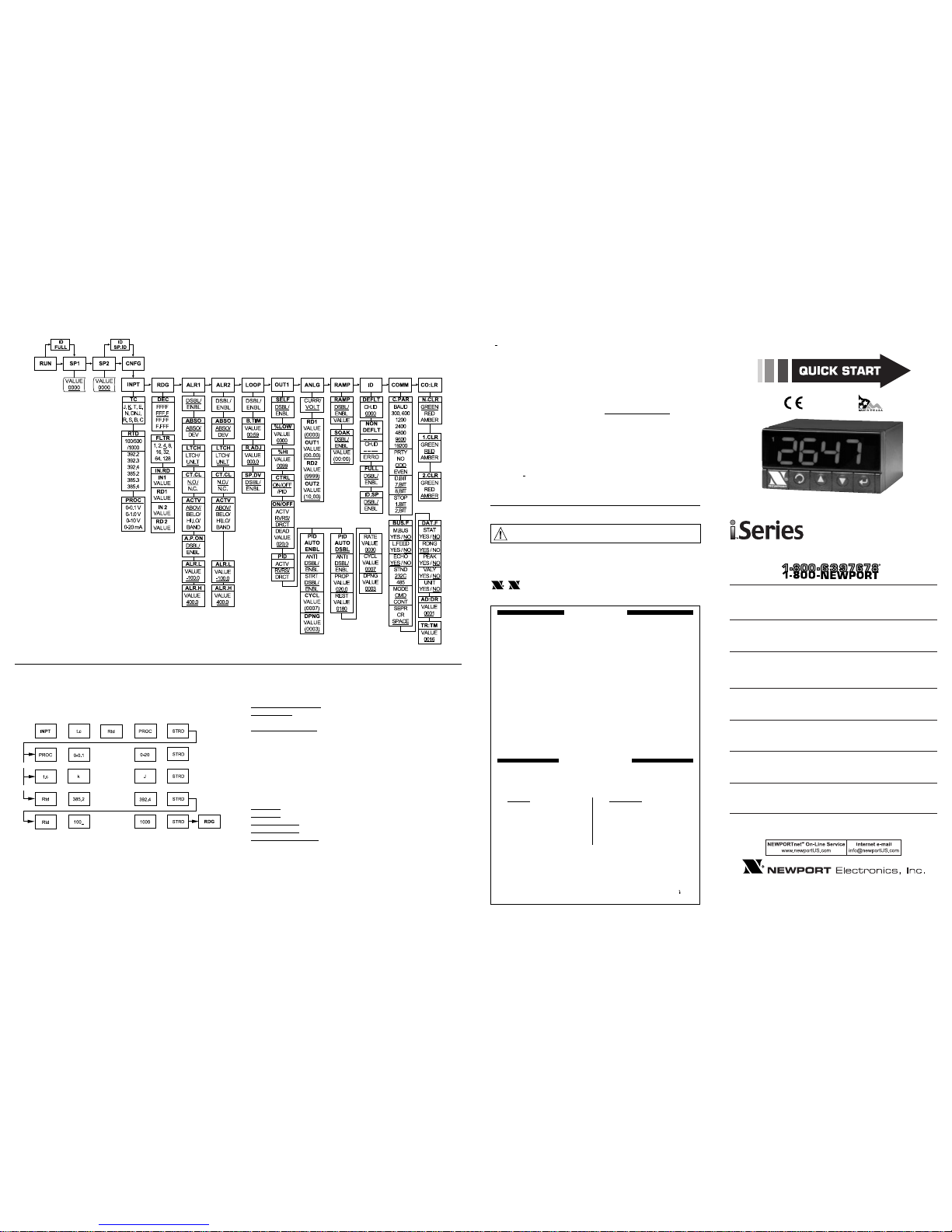
Below is a flowchart showing how to navigate through all
top level menus by pressing the d and a buttons.
_____Underline denotes factory default setup
FLOW CHART
DISPLAY COLOR SETUP (examples)
Example 1:
Output 1 & Output 2: SSR
Alarm setup: Absolute, Above, Alarm 2 HI Value
"ALR.H" =200, Alarm 1 HI Value "ALR.H"=400
Color Display setup: Normal Color "N.CLR"=Green,
Alarm 1 Color "1.CLR"=Amber, Alarm 2 Color "2.CLR"=Red
Display color change sequence:
GREEN | RED | AMBER
•-➤
----------------•-----------------------•--------------------------------
➤
0 AL2.H=200 AL1.H=400
Example 2:
Output 1: Relay, Set Point 1 = 200,
Output 2: Relay, Set Point 2 = 200
Alarm 1 setup: Deviation, Band, "ALR.H" = 20
Alarm 2 setup: Deviation, Hi/Low, "ALR.H = 10", "ALR.L = 5"
Color Display setup: "N.CLR"=Green, "1.CLR"=Amber,
"2.CLR"=Red
Display color change sequence:
AMBER | RED | GREEN | GREEN | RED | AMBER
•-➤
--------•----------•--------------•--------------•----------•------------
➤
0 180 195 200 210 220
INPUT MENU SETUP
(operation example)
Below is a flowchart showing how to navigate through the
submenus of Input menu item by pressing the front buttons.
dbbd
d
b
b
• • •
d
b
b
• • •
d
d
d
b
b
• • •
d
d
b
b
• • •
d
a
a
For immediate technical or application assistance please call:
Newport Electronics, Inc.
2229 South Yale Street • Santa Ana, CA • 92704 • U.S.A.
TEL: (714) 540-4914 • FAX: (714) 546-3022
Toll Free: 1-800-639-7678 • http://www.newportUS.com • e-mail:info@newportUS.com
ISO 9001 Certified
Newport Technologies, Inc.
976 Bergar • Laval (Quebec) • H7L 5A1 • Canada
TEL: (514) 335-3183 • FAX: (514) 856-6886
Toll Free: 1-800-639-7678 • http://www.newport.ca • e-mail:sales@newport.ca
Newport Electronics, Ltd.
One Omega Drive • River Bend Technology Centre
Northbank, Irlam • Manchester M44 5BD • United Kingdom
Tel: +44 161 777 6611 • FAX: +44 161 777 6622
Toll Free: 0800 488 488 • http://www.newportuk.co.uk • e-mail:sales@newportuk.co.uk
Newport Electronics B.V.
Postbus 8034 • 1180 LA Amstelveen • The Netherlands
TEL: +31 20 3472121 • FAX: +31 20 6434643
Toll Free: 0800 0993344 • http://www.newport.nl • e-mail: sales@newport.nl
Newport Electronics spol s.r.o.
Rudé armády 1868, 733 01 Karviná 8 • Czech Republic
TEL: +420 69 6311899 • FAX: +420 69 6311114
Toll Free: 0800-1-66342 • http://www.newport.cz • e-mail: sales@newport.cz
Newport Electronics GmbH
Daimlerstrasse 26 • D-75392 Deckenpfronn • Germany
TEL: 49 7056 9398-0 • FAX: 49 7056 9398-29
Toll Free: 0800 / 6397678 • http://www.newport.de • e-mail: sales@newport.de
Newport Electronique S.A.R.L.
9, rue Denis Papin • 78190 Trappes • France
TEL: +33 130 621 400 • FAX: +33 130 699 120
Toll Free: 0800-4-06342 • http://www.newport.fr • e-mail: sales@newport.fr
Mexico and Latin America
TEL: 001-800-826-6342 • FAX: 001 (203) 359-7807
En Español: 001 (203) 359-7803
It is the policy of NEWPORT to comply with all worldwide safety and EMC/EMI regulations that apply.
NEWPORTis constantly pursuing certification of its products to the European New Approach Directives.
NEWPORT will add the CE mark to every appropriate device upon certification.
The information contained in this document is believed to be correct, but NEWPORT Electronics, Inc.
accepts no liability for any errors it contains, and reserves the right to alter specifications without notice.
TRADEMARK NOTICE:
, NEWPORT®, NEWPORT®, and the “Meter Bezel Design”
are Trademarks of NEWPORTELECTRONICS, INC.
This device is marked with the international caution symbol. It is important to read the
Setup Guide before installing or commissioning this device, as the guide contains important
information relating to safety and EMC.
WARNING: These products are not designed for use in, and should not be used for, patientconnected applications.
WARRANTY/DISCLAIMER
NEWPORT Electronics, Inc. warrants this unit to be free of defects in materials and workmanship for a period of
one (1) year from the date of purchase. In addition to NEWPORT’s standard warranty period, NEWPORT
Electronics will extend the warranty period for four (4) additional years if the warranty card enclosed with each
instrument is returned to NEWPORT.
If the unit malfunctions, it must be returned to the factory for evaluation. NEWPORT’s Customer Service
Department will issue an Authorized Return (AR) number immediately upon phone or written request. Upon
examination by NEWPORT, if the unit is found to be defective, it will be repaired or replaced at no charge.
NEWPORT’s WARRANTYdoes not apply to defects resulting from any action of the purchaser, including but not
limited to mishandling, improper interfacing, operation outside of design limits, improper repair, or unauthorized
modification. This WARRANTY is VOID if the unit shows evidence of having been tampered with or shows
evidence of having been damaged as a result of excessive corrosion; or current, heat, moisture or vibration;
improper specification; misapplication; misuse or other operating conditions outside of NEWPORT’s control.
Components which wear are not warranted, including but not limited to contact points, fuses, and triacs.
NEWPORT is pleased to offer suggestions on the use of its various products. However, NEWPORT neither
assumes responsibility for any omissions or errors nor assumes liability for any damages that result from
the use of its products in accordance with information provided by NEWPORT, either verbal or written.
NEWPORT warrants only that the parts manufactured by it will be as specified and free of defects.
NEWPORT MAKES NO OTHER WARRANTIES OR REPRESENTATIONS OF ANYKIND WHATSOEVER,
EXPRESS OR IMPLIED, EXCEPT THAT OF TITLE, AND ALL IMPLIED WARRANTIES INCLUDING ANY
WARRANTY OF MERCHANTABILITY AND FITNESS FOR A PARTICULAR PURPOSE ARE HEREBY
DISCLAIMED.
LIMITATION OF LIABILITY: The remedies of purchaser set forth herein are exclusive, and the total liability
of NEWPORT with respect to this order, whether based on contract, warranty, negligence, indemnification,
strict liability or otherwise, shall not exceed the purchase price of the component upon which liability is
based. In no event shall NEWPORT be liable for consequential, incidental or special damages.
CONDITIONS: Equipment sold by NEWPORT is not intended to be used, nor shall it be used: (1) as a "Basic
Component" under 10 CFR 21 (NRC), used in or with any nuclear installation or activity; or (2) in medical
applications or used on humans. Should any Product(s) be used in or with any nuclear installation or activity,
medical application, or used on humans, or misused in any way, NEWPORTassumes no responsibility as set forth
in our basic WARRANTY/DISCLAIMER language, and, additionally purchaser will indemnify NEWPORTand hold
NEWPORT harmless from any liability or damage whatsoever arising out of the use of the Product(s) in such a
manner.
RETURN REQUEST/INQUIRIES
Direct all warranty and repair requests/inquiries to the NEWPORT Customer Service Department. BEFORE
RETURNING ANY PRODUCT(S) TO NEWPORT, PURCHASER MUSTOBTAIN AN AUTHORIZED RETURN
(AR) NUMBER FROM NEWPORT’S CUSTOMER SERVICE DEPARTMENT (IN ORDER TO AVOID
PROCESSING DELAYS). The assigned AR number should then be marked on the outside of the return package
and on any correspondence.
The purchaser is responsible for shipping charges, freight, insurance and proper packaging to prevent breakage
in transit.
FOR WARRANTYRETURNS, FOR NON-WARRANTYREPAIRS,
please consult NEWPORT for current have the following information available
repair BEFORE contacting NEWPORT: charges. Have the following information
available BEFORE contacting NEWPORT:
1. Purchase Order number under which 1. Purchase Order number to cover the
the product was PURCHASED, COST the repair,
2. Model and serial number of the 2. Model and serial number of product,
product under warranty, and and
3. Repair instructions and/or specific 3. Repair instructions and/or specific
problems relative to the product. problems relative to the product.
NEWPORT’s policy is to make running changes, not model changes, whenever an improvement is possible. This
affords our customers the latest in technology and engineering.
NEWPORT is a registered trademark of NEWPORTElectronics, Inc.
© Copyright 2001 NEWPORT Electronics, Inc. All rights reserved.
This document may not be copied, photocopied, reproduced, translated, or reduced to any electronic medium or
machine-readable form, in whole or in part, without the prior written consent of NEWPORT Electronics, Inc.
PATENT NOTICE:This product is covered by one or more of the following patents: U.S. Pat. No. Des. 336,895;
5,274,577; 6,243,021 / Canada 2052599; 2052600 / Italy 1249456; 1250938 / France Brevet No. 91 12756 / Spain
2039150; 2048066 / UK Patent No. GB2 249 837; GB2 248 954 / Germany DE 41 34398 C2. The ™is a
Trademark of OMEGAEngineering, Inc. USED UNDER LICENSE. Other U.S. and International patents pending or
applied for.
Panel Mounting Instruction:
1. Using the dimensions from the panel cutout diagram
shown above, cut an opening in the panel.
2. Remove sleeve from the rear of the case by removing
thumbnuts.
3. Insert the unit into the opening from the front of the
panel, so the gasket seals between the bezel and the
front of the panel.
4. Slip the sleeve over the rear of the case.
5. Tighten the thumbnuts to hold the meter firmly in the panel.
Disassembly Instruction:
If necessary, the meter may be removed from the panel and
opened.
Warning: Disconnect all ac power from the unit
before proceeding.
1. Remove all wiring connections from the rear of the
instrument, by unplugging the power and input connectors.
2. Remove both thumbnuts and set aside.
3. Remove the sleeve and set aside.
4. Remove the meter from the panel and bend the side
panel detents on the case outward to release the board.
Pull the board assembly out of the case.
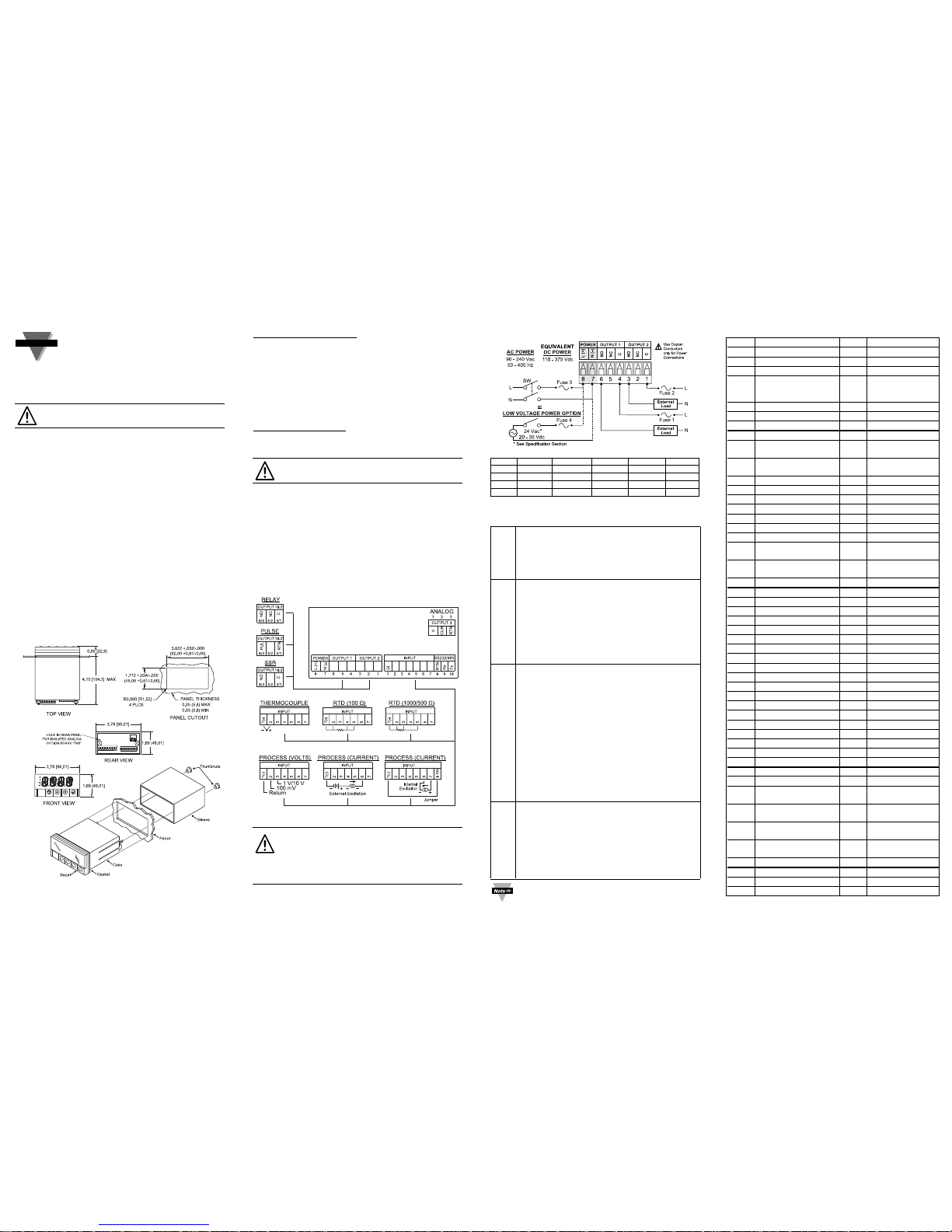
WIRING
Wire the instrument according to the schematic below.
Warning: Do not connect ac power to your
device until you have completed all input and
output connections. This device must only be
installed by a specially trained electrician with
corresponding qualifications. Failure to follow all
instructions and warnings may result in injury!
This Quick Start Reference provides information
on setting up your instrument for basic operation.
The latest complete Communication and
Operational Manual as well as free Software and
ActiveX Controls are available at
www.newportUS.com/i or on the CD-ROM
enclosed with your shipment.
SAFETY CONSIDERATION
This device is marked with the international
Caution symbol.
The Controller is a panel mount device protected in
accordance with Class II of IEC 1010. Remember that the
controller has no power-on switch. Building installation
should include a switch or circuit-breaker that must be
compliant to IEC 947-1 and 947-3.
SAFETY:
• Do not exceed voltage rating on the label located on
the top of the instrument housing.
• Always disconnect power before changing signal and
power connection.
• Do not use this instrument on a work bench without
its case for safety reasons.
• Do not operate this instrument in flammable or
explosive atmospheres.
• Do not expose this instrument to rain or moisture.
EMC:
• Whenever EMC is an issue, always use shielded cables.
• Never run signal and power wires in the same conduit.
• Use signal wire connections with twisted-pair cables.
• Install Ferrite Bead(s) on signal wire close to the
instrument if EMC problems persist.
MOUNTING
START HERE
Connect the main power connections in the figure shown
below.
FUSE Connector Output Type For 115Vac For 230Vac DC
FUSE 1 Output 1 Relay 3 A(T) 3 A(T) FUSE 2 Output 2 Relay 3 A(T) 3 A(T) FUSE 3 Power N/A 100 mA(T) 100 mA(T) 100 mA(T)
FUSE 4 Power N/A N/A N/A 400 mA(T)
CONFIGURATION
Button Functions in Configuration Mode
•
To enter the Menu, the user must first press abutton.
• Use this button to advance/navigate to the next
menu item. The user can navigate through all the
top level menus by pressing a.
• While a parameter is being modified, press this
button to escape without saving the parameter.
• Press the up b button to scroll through “flashing”
selections. When a numerical value is displayed
press this key to increase value of a parameter that
is currently being modified.
• Holding the b button down for approximately
3 seconds will speed up the rate at which the set
point value is incremented.
• In the Run Mode pressing b causes the display to
flash the PEAK value – press again to return to the
Run Mode.
• Press the down c button to go back to a previous
Top Level Menu item.
• Press this button twice to reset the controller to
the Run Mode.
• When a numerical value is flashing (except set point
value) press this button to scroll digits from left to
right allowing the user to select the desired digit to
modify.
•
When a set point value is displayed press this button
to decrease value of a set point that is currently being
modified. Holding the cbutton down for
approximately 3 seconds will speed up the rate at
which the setpoint value is decremented.
• In the Run Mode pressing c causes the display to
flash the Valley value - press again to return to the
Run Mode.
• Press this button to access the submenus from a
Top Level Menu item.
• Press this button to store a submenu selection or
after entering a value — the display will flash a
STRD
message to confirm your selection.
• Press this button to reset flashing PEAK value.
• In the Run Mode, press ENTER twice to enable
Standby Mode with flashing
STBY
- press again to
return to the Run Mode.
a
d
c
b
(UP)
MENU
(DOWN)
ENTER
Reset: Except for Alarms, modifying any settings of
the menu configuration will reset the controller prior
to resuming Run Mode.
DISPLAY ABBREVIATIONS
SP1 Set Point 1 Value SP2 Set Point 2 Value
CNFG Configuration Menu
INPt Input Type Menu t.c
Thermocouple Input
k. . .J Thermocouple Type Rtd RTD Input
385.2 RTD Curve and 100 _ 100 _/500 _/1000 _
. . . . Connection Type . . . . RTD Sensor
392.4 (2, 3, 4-Wire) 1000
PROC Process Input
0 - 0.1 100 mV Input Voltage 0 - 1.0 1 V Input Voltage
0 - 20 20 mA Input Current 0 - 10 10 V Input Voltage
RdG Reading Configuration dEC Decimal Point
F.FFF. Decimal Point FLtR Filter Constant
..FFFF Position
0001.. Filter Constant Value IN.Rd
Input/Reading Scale
..0128 and Offset Menu
IN 1 Input 1 IN 2 Input 2
Rd 1 Reading 1 Rd 2 Reading 2
ALR1 Alarm 1 Menu AbSo Absolute Mode
_dEV Deviation Mode LtcH Latched Mode
UNLt Unlatched Mode Ct.CL Contact Closure
N.o. Normally Open N.c. Normally Closed
ActV Active Type AboV Active Above
bELo Active Below Hi.Lo Above High/Below
Low
bANd Above or Below Band A.P.oN
Alarm
Enable/Disable
at Power On
ALR.L Alarm Low Value ALR.H Alarm High Value
ALR.2 Alarm 2 Menu
LOOP Loop Break Menu b.tIM Loop Break Time
R.AdJ Reading Adjust SP.dN Set Point Deviation
OUt1 Output 1 Menu SELF Manual Control
º
ºLO Percent Low
º
ºHI Percent High
CtRL Control Type ON.OF On/Off Control
4 - 20 Amplitude Control PId PID Control
ActN Action Type RVRS Reverse Action
dRct Direct Action ANt1 Anti Integral
AUto Auto PID A.tUN Auto Tune PID
StRt Start Auto Tune PID PRoP Proportional Band
RESt Reset Setup RAtE Rate Setup
CYCL Cycle Time dPNG Damping Factor
dEAd Dead Band
ANLG Analog Output
VoLt Voltage Output CURR Current Output
Out.1 Output 1 Rd 1 Reading 1
Out.2 Output 2 Rd 2 Reading 2
RAMP Ramp Time SOAk Soak Time
Id ID Code Menu CH.Id Change ID Code
FULL Full ID SP.Id Set Point ID
COMM Communication Option* NONE Communication is
Not Installed
COLR Display Color Selection N.CLR Normal Color
Display
1.CLR Alarm 1 Color Display 2.CLR Alarm 2 Color
Display
REd Display Color is Red AMbR Display Color is
Amber
GRN Display Color is Green
ENbL Enable dSbL Disable
ERRo Error + OL Input (+) Overload
+OPN Input (+) Open
* For abbreviations of Communication Option see Communication Manual.
 Loading...