

Newport i8-AL, i16-AL, i32-AL Owner's Manual
Temperature/Process
Limit Alarm Controller
i8-AL, i16-AL, i32-AL
Operator’s Manual
www.newportUS.com/manuals

Additional products from
Counters
Frequency Meters
PID Controllers
Clock/Timers
Printers
Process Meters
On/Off
Controllers
Recorders
Relative
Humidity
Transmitters
Thermocouples
Thermistors
Wire
Rate Meters
Timers
Totalizers
Strain Gauge
Meters
Voltmeters
Multimeters
Soldering Iron
Testers
pH pens
pH Controllers
pH Electrodes
RTDs
Thermowells
Flow Sensors
Wireless
For Immediate Assistance
In the U.S.A. and Canada: 1-800-NEWPORT
In Mexico: (95) 800-NEWPORT
SM
®
Or call your local NEWPORT Office.
The information contained in this document is believed to be correct but NEWPORT Electronics, Inc. accepts no liability for any errors it
contains, and reserves the right to alter specifications without notice.
WARNING: These products are not designed for use in, and should not be used for, patient connected applications.
TRADEMARK NOTICE:
of NEWPORT Electronics, Inc.
PATENT NOTICE: This product is covered by one or more of the following patents: U.S. Pat. No. Des. 336,895; 5,274,577;
6,243,021 / CANADA 2052599; 2052600/ ITALY 1249456; 1250938 / FRANCE BREVET No. 91 12756 / SPAIN 2039150; 2048066 /
UK PATENT No. GB2 249 837; GB2 248 954 / GERMANY DE 41 34398 C2. The
Under License. Other US and International Patents pending or applied for.
This device is marked with the international caution symbol. It is important to read the Setup Guide before installing or
commissioning this device as it contains important information relating to safety and EMC.
Newport Electronics, Inc.
2229 South Yale Street
, NEWPORT, NEWPORT®, newportUS.com, and the “Meter Bezel Design” are trademarks
®
is a Trademark of OMEGA Engineering, Inc. Used
www.newportUS.com
info@newportUS.com
Santa Ana, CA 92704

TABLE OF CONTENTS
Part 1: Introduction .....................................................................................1
1.1 Description .....................................................................................2
1.2 Safety Considerations ....................................................................3
1.3 Before You Begin ...........................................................................4
Part 2: Setup ................................................................................................5
2.1 Front Panel ...................................................................................5
2.2 Disassembly ...................................................................................6
2.3 Electrical Installation ......................................................................7
2.3.1 Power Connections ............................................................7
2.3.3 Thermocouple - Input Connection ......................................8
2.3.4 Two / Three / Four Wire RTD-Hookups .............................9
2.3.5 Process Current - Wiring Hookup ....................................10
2.3.6 Process Voltage - Wiring Hookup ....................................10
2.3.7 Wiring Outputs - Wiring Hookup .......................................11
Part 3: Operation: Configuration Mode ...................................................12
Turning your device On for the First Time
Buttons Functions in Configuration Mode
3.2 Menu Configuration .....................................................................13
3.2.1 ID Number ........................................................................14
3.2.2 Setpoints .........................................................................15
3.2.3 Configuration Menu ..........................................................16
3.2.4 Input Type Menu .............................................................17
3.2.4.1 Input Type (Thermocouple) ................................ 18
3.2.4.2 Input Type (RTD) ............................................... 19
3.2.4.3 Input Type (Process) .......................................... 20
3.2.5 Reading Configuration Menu ..........................................21
3.2.6 Alarm 1 Menu ..................................................................25
3.2.7 Alarm 2 Menu ...................................................................29
3.2.8 Reading Adjust Menu .......................................................30
3.2.9 Setpoint Deviation Menu/Field Calibration ......................31
3.2.10 ID Code Menu .................................................................32
3.2.11 Display Color Selection Menu ..........................................41
3.1 Introduction .................................................................................12
Part 4: Specifications......................................................................................44
Part 5: Factory Preset Values .......................................................................47
CE APPROVAL INFORMATION .....................................................................48
i

LIST OF FIGURES:
Figure 2.1 Front Panel Display ........................................................................5
Figure 2.2 Rear Panel Input Connector Labels ..............................................6
Figure 2.4 Main Power Connections ..............................................................7
Figure 2.5 Thermocouple Wiring Hookup .......................................................8
Figure 2.6 Two/Three/Four-Wire RTD Wiring Hookup
a) RTD-1000 ohm/RTD-500 ohm ...................................................9
b) RTD-100 ohm ...........................................................................9
Figure 2.7 Process Current Wiring Hookup
(Internal and External Excitation) ................................................10
Figure 2.8 Process Voltage Wiring Hookup
a) With Sensor Excitation ............................................................10
b) Without Sensor Excitation ........................................................10
Figure 2.9 Mechanical Relay Outputs Wiring Hookup ..................................11
Figure 2.10 Excitation Output .........................................................................11
Figure 3.1 Flow Chart for ID and Setpoints . .................................................13
Figure 3.2 Flow Chart for Configuration Menu ..............................................16
Figure 3.3 Flow Chart for Input Type Menu .................................................17
Figure 3.4 Flow Chart for Reading Configuration .........................................21
Figure 3.5 Flow Chart for Alarm 1 .................................................................25
Figure 3.6 Flow Chart for Alarm 2 .................................................................29
Figure 3.7 Flow Chart for Reading Adjust .....................................................30
Figure 3.8 Flow Chart for Setpoint Deviation/Field Calibration ....................31
Figure 3.9 Flow Chart for ID Code ...............................................................32
Figure 3.10 Flow Chart for Display Color Selection ........................................41
LIST OF TABLES:
Table 2.1 Front Panel Annunciators ..............................................................5
Table 2.2 Rear Panel Connector ..................................................................6
Table 2.3 Power Connections .......................................................................7
Table 2.4 TC Wire Color Chart .....................................................................8
Table 3.1 Button Function in Configuration Mode ........................................12
Table 3.2 Conversion Table .........................................................................24
Table 4.1 Input Properties .. .........................................................................46
Table 5.1 Factory Preset Values .................................................................47
ii
NOTES, WARNINGS and CAUTIONS
Information that is especially important to note is identied by the following labels:
• NOTE
• WARNING or CAUTION
• IMPORTANT
• TIP
NOTE: Provide you with information that is important to successfully
setup and use the Programmable Digital System.
CAUTION or WARNING: Tells you about the risk of
electrical shock.
CAUTION, WARNING or IMPORTANT: Tells you of circumstances or
practices that can affect the instrument’s functionality and must refer to
accompanying documents.
TIP: Provides you helpful hints.
PART 1
INTRODUCTION
1.1 Description
The iSeries Limit Alarm Controller offers unparalleled exibility in process
measurement and alarm applications, accepting 10 different thermocouple types,
18 RTD combinations or 4 process voltage/current inputs and providing 2 relay
alarm outputs and a large multi-color, programmable display. Easily congured
options include 11 different alarm conditions and the unit supports an external
reset input and a buzzer audio annunciator.
Front panel conguration switches allow the user to select the type of input, the
alarm conditions and the resulting display color. Process inputs are fully scalable,
supporting virtually all engineering units with a selectable decimal point providing
a perfect solution for pressure, ow or other process inputs.
Standard features include a built-in 24 Vdc excitation source for transmitters or
other devices and a universal power supply that accepts 90 to 240 Vac. A low
power option is available that supports 24 Vac or 12 to 36 Vdc.
1
1.2 Safety Considerations
This device is marked with the international caution symbol. It is
important to read this manual before installing or commissioning this
device as it contains important information relating to Safety and
EMC (Electromagnetic Compatibility).
This device is a panel mount device protected in accordance with
EN 61010-1:2001, electrical safety requirements for electrical
equipment for measurement, control and laboratory. Installation of this
device should be done by qualied personnel. In order to ensure safe
operation, the following instructions should be followed.
This device has no power-on switch. An external switch or circuitbreaker shall be included in the building installation as a disconnecting
device. It shall be marked to indicate this function, and it shall be in
close proximity to the equipment within easy reach of the operator.
The switch or circuit-breaker shall meet the relevant requirements of
IEC 947–1 and IEC 947-3 (International Electrotechnical Commission).
The switch shall not be incorporated in the main supply cord.
Furthermore, to provide protection against excessive energy being
drawn from the main supply in case of a fault in the equipment, an
overcurrent protection device shall be installed.
• Do not exceed voltage rating on the label located on the top of
the device housing.
• Always disconnect power before changing signal and power
connections.
• Do not use this device on a work bench without its case for
safety reasons.
• Do not operate this device in ammable or explosive atmospheres.
• Unit mounting should allow for adequate ventilation to ensure
device does not exceed operating temperature rating.
• Use electrical wires with adequate size to handle mechanical
strain and power requirements. Install without exposing bare wire
outside the connector to minimize electrical shock hazards.
EMC Considerations
• Whenever EMC is an issue, always use shielded cables.
• Never run signal and power wires in the same conduit.
• Use signal wire connections with twisted-pair cables.
• Install Ferrite Bead(s) on signal wires close to the device if
EMC problems persist.
Failure to follow all instructions and warnings may result in injury!
2

1.3 Before you Begin
Inspecting Your Shipment:
Remove the packing slip and verify that you have received everything
listed. Inspect the container and equipment for signs of damage as
soon as you receive the shipment. Note any evidence of rough handling
in transit. Immediately report any damage to the shipping agent. The
carrier will not honor damage claims unless all shipping material is
saved for inspection. After examining and removing the contents, save
the packing material and carton in the event reshipment is necessary.
Customer Service:
If you need assistance, please call the nearest Customer Service
Department, listed in this manual.
Manuals:
The latest Operation Manual is available from the website listed in this
manual.
To Reset the Meter:
When the device is in the “MENU” Mode, push c once to direct device
one step backward of the top menu item.
Push c twice to reset device, prior to resuming “Run” Mode except
after “Alarms”, that will go to the “Run” Mode without resetting the
device.
When using external reset switch: when the device is in the “RUN”
Mode, push d twice to disable all outputs and alarms. It is now in
“STANDBY” Mode.
Push d once more to resume “RUN” Mode.
Push d twice to disable the system during an EMERGENCY.
3
PART 2
SETUP
2.1 Front Panel
Figure 2.1 Front Panel Display
Table 2.1 Front Annunciators
1 Setpoint 1/ Alarm 1 indicator
2 Setpoint 2/ Alarm 2 indicator
ºC °C unit indicator
ºF °F unit indicator
a
b
c
d
* See Part 3 Operation: Configuration Mode
Changes display to Conguration Mode and advances through
menu items*
Used in Program Mode and Peak Recall*
Used in Program Mode and Valley Recall*
Accesses submenus in Conguration Mode and stores selected
values*
4
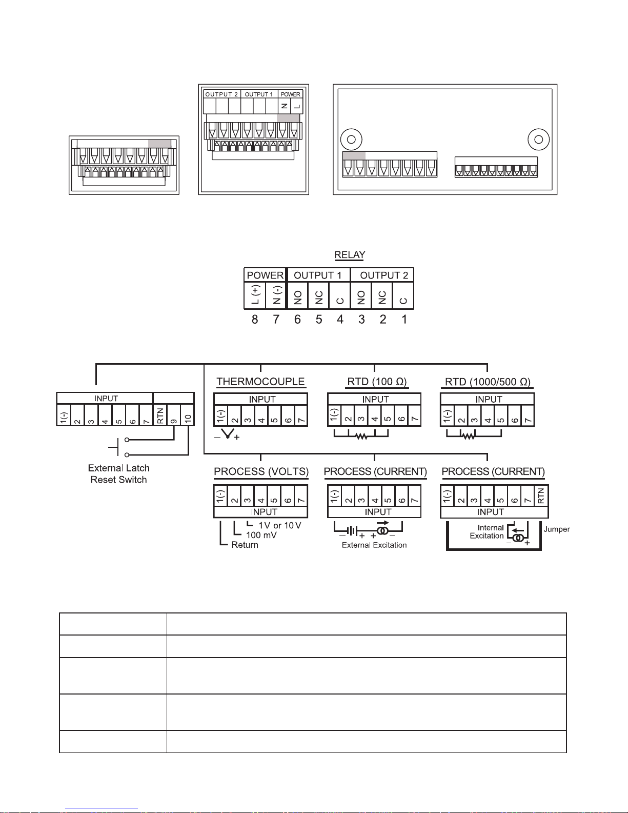
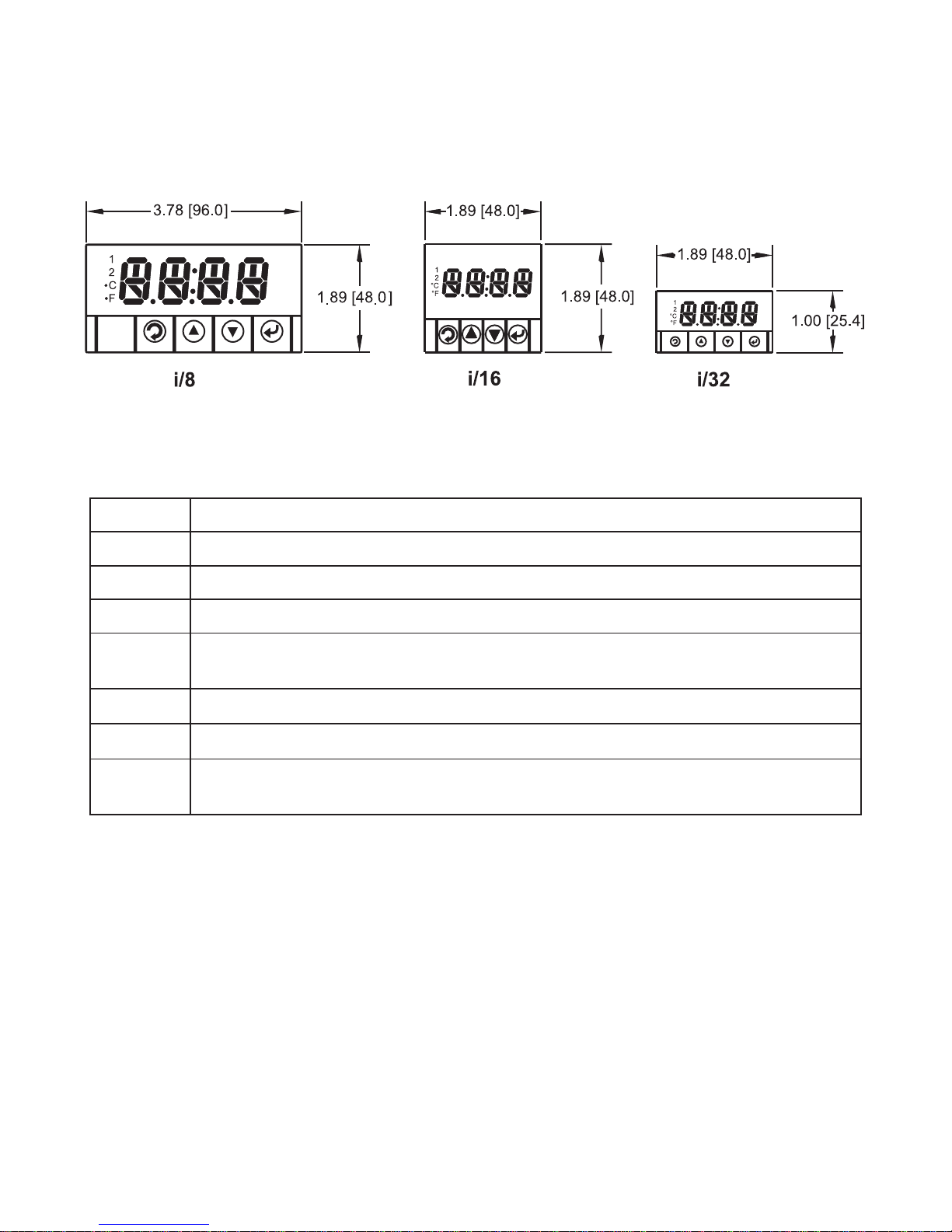
2.2 Rear Panel Connections
1/32 DIN 1/16 DIN 1/8 DIN
1 2 3 4 5 6 7 8
1 2 3 4 5 6 7 8
1 2 3 4 5 6 7 8 9 10
8 7 6 5 4 3 2 1
1 2 3 4 5 6 7 8 9 10
1 2 3 4 5 6 7 8 9 10
L N -OUTPUTS- -INPUTS-L N -OUTPUTS-
Figure 2.2 Rear Panel
Figure 2.3 Rear Panel Input Connector Labels
Table 2.2 Rear Panel Connector
POWER AC/DC Power Connector: All models
INPUT Input Connector: All models TC, PR (Process), RTD
ALARM 1
OUTPUT
ALARM 2
OUTPUT
Mechanical Relay SPDT
Mechanical Relay SPDT
OPTION Excitation, not available with low power option (-DC)
5
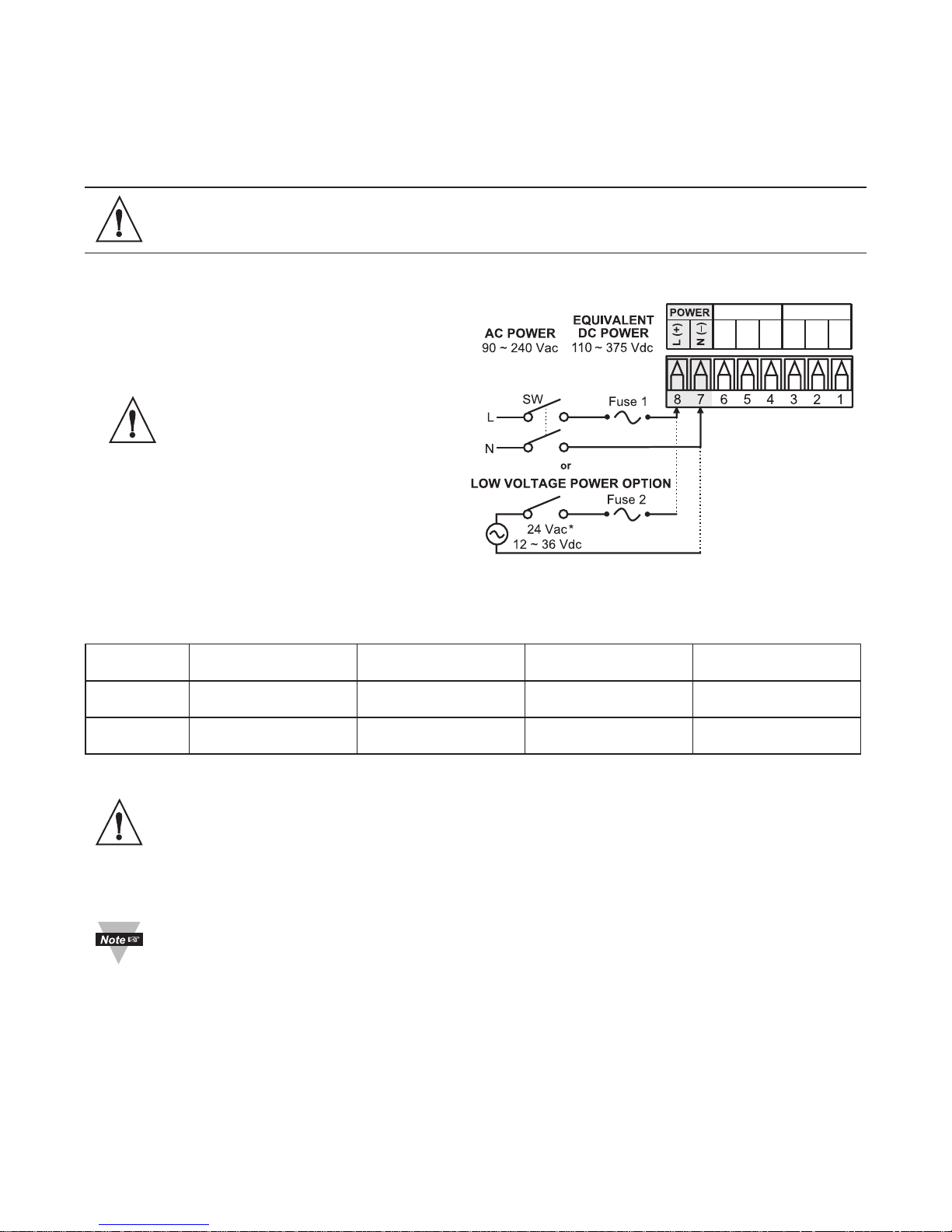
2.3 Electrical Installation
2.3.1 Power Connections
Caution: Do not connect power to your device until you have completed
all input and output connections. Failure to do so may result in injury!
Connect the main power connections as shown in Figure 2.4.
Use copper conductors
only for power connections
Figure 2.4 Main Power Connections
Table 2.3 Power Connections
FUSE Connector For 115 Vac For 230 Vac DC
FUSE 1 Power* 100 mA(T) 100 mA(T) 100 mA(T)
FUSE 2 Power* N/A N/A 400 mA(T)
For the low voltage power option, in order to maintain the same degree of
protection as the standard high voltage input power units (90 to 240 Vac),
always use a Safety Agency Approved DC or AC source with the same
Overvoltage Category and pollution degree as the standard AC unit
(90 to 240 Vac).
The Safety European Standard EN61010-1 for measurement, control,
and laboratory equipment requires that fuses must be specied based
on IEC127. This standard species for a Time-lag fuse, the letter code
“T”. The above recommended fuses are of the type IEC127-2-sheet III.
Be aware that there are signicant differences between the requirements
listed in the UL 248-14/CSA 248.14 and the IEC 127 fuse standards. As
a result, no single fuse can carry all approval listings. A 1.0 Amp IEC fuse
is approximately equivalent to a 1.4 Amp UL/CSA fuse. It is advised to
consult the manufacturer’s data sheets for a cross-reference.
6
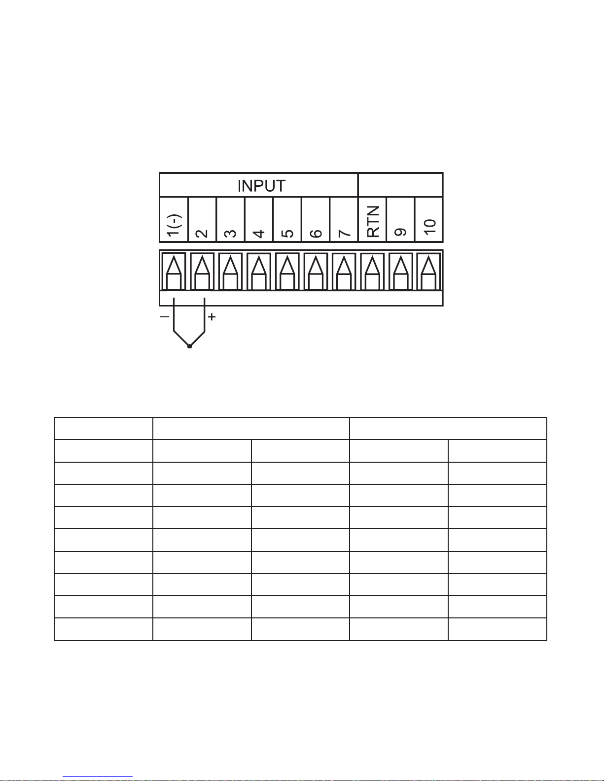
2.3.2 Thermocouple
The gure below shows the wiring hookup for any thermocouple type.
For example, for Type K hookup, connect the yellow wire to the “2” terminal and
the red wire to the “1(-)” terminal.
When conguring your device, select Thermocouple and Thermocouple
Type in the Input Type menu (see Part 3).
Figure 2.5 Thermocouple Wiring Hookup
Table 2.4 TC Wire Color Chart
Type Input Connector Jacket (External Insulation)
Terminal 1 (-) Terminal 2 (+) Extension Grade
J Red White Dark-Brown Black
K Red Yellow Dark-Brown Yellow
T Red Blue Dark-Brown Blue
E Red Purple Dark-Brown Purple
N Red Orange Dark-Brown Brown
R Red Black - Green
S Red Black - Green
B Red Gray - Black
7
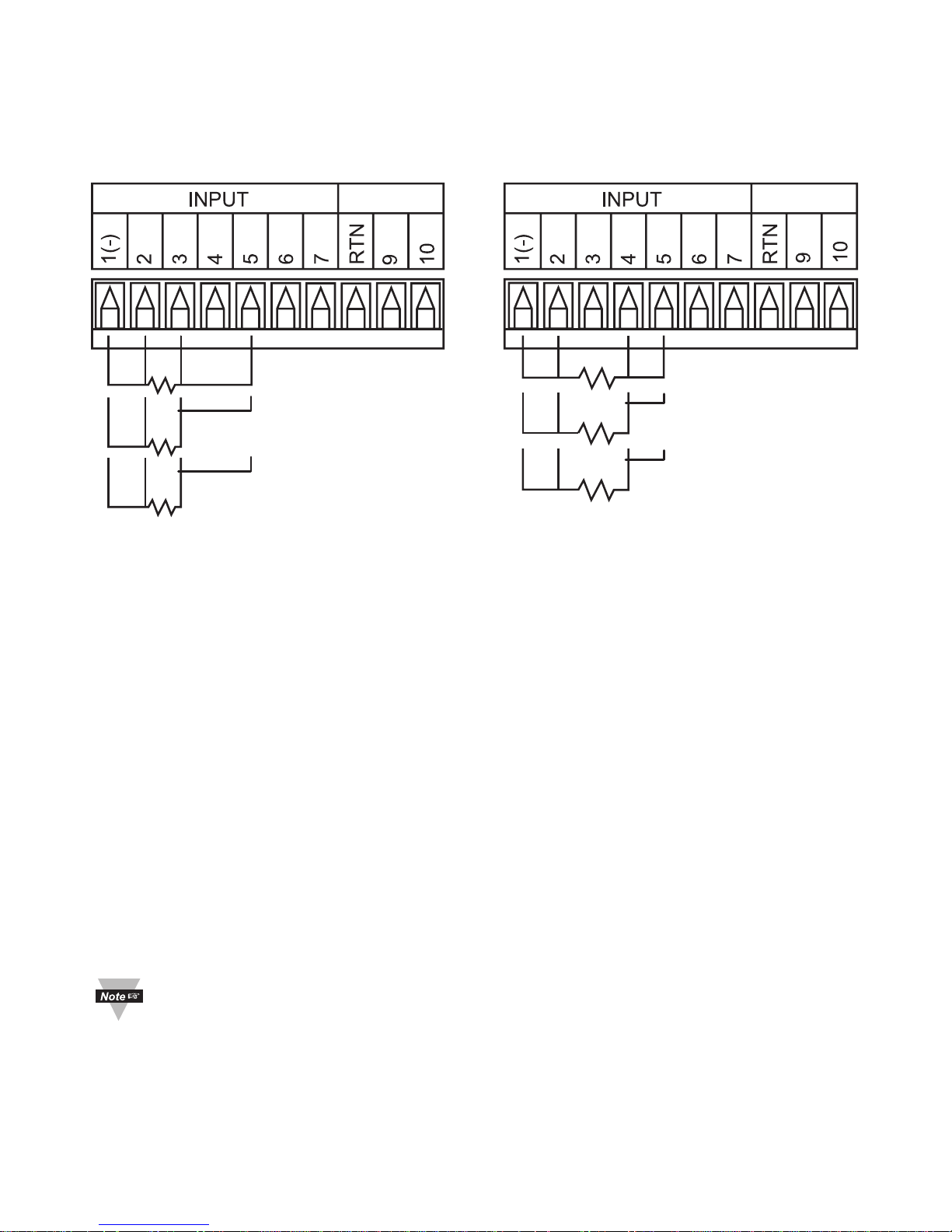
2.3.3 Two/Three/Four-Wire RTD
The gures below show the input connections and input connector jumpers
(shown in bold lines) required to hookup a 2-, 3- or 4-wire RTD.
RTD (1000/500) 4-Wire
RTD (1000/500) 3-Wire
RTD (1000/500) 2-Wire
RTD (100) 4-Wire
RTD (100) 3-Wire
RTD (100) 2-Wire
Figure 2.6 a) RTD-100 ohm and b) RTD-100 ohm Wiring Hookup
500 ohm Wiring
Hookup
The two-wire connection is simplest method, but does not compensate for
lead-wire temperature change and often requires calibration to cancel lead-wire
resistance offset.
The three-wire connection works best with RTD leads closely equal in
resistance. The device measures the RTD, plus upper and lower lead drop
voltage and the subtracts twice the measured drop in the lower supply
current lead producing excellent lead-resistance cancellation for balanced
measurements.
The four-wire RTD hookup is applicable to unbalanced lead resistance and
enables the device to measure and subtract the lead voltage, which produces
the best lead-resistance cancellation.
When conguring your device, select RTD type and RTD value in the Input
Type menu (see Part 3).
If the input wires of the meter get disconnected or broken, it will display
+OPN
“Input (+) Open” message except in case of 500/1000 Ω 2-wire
RTD. In this case the display shows
For safety purpose you may want to set up your alarm to be triggered
when input is open. See Alarm 1 & 2 Sections 3.2.6, 3.2.7 for details.
8
-OPN
“Input (-) Open” message.
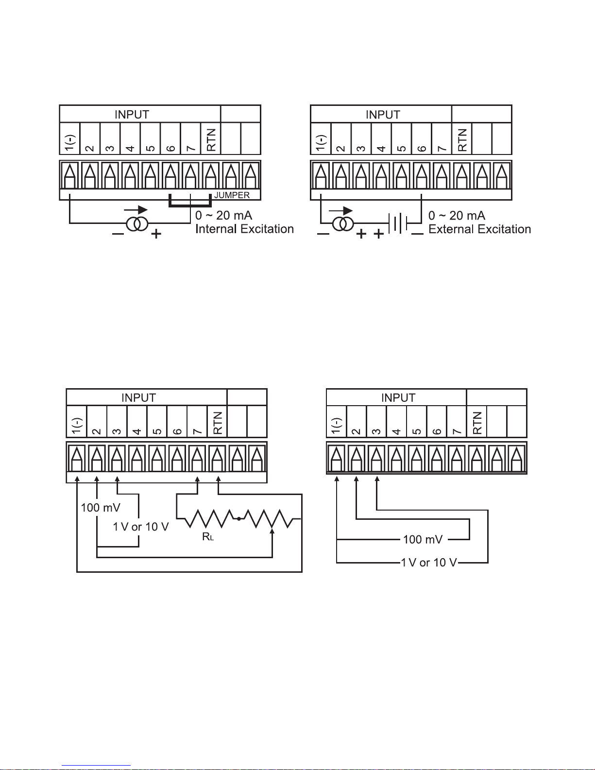
2.3.4 Process Current
The gure below shows the wiring hookup for Process Current 0 – 20 mA.
Figure 2.7 Process Current Wiring Hookup
(Internal and External Excitation)
When conguring your device, select Process Type in the Input Type Menu
(see Part 3).
2.3.5 Process Voltage
The gure below shows the wiring hookup for Process Voltage 0 – 100 mV,
0 – 1 V, 0 – 10 V.
Figure 2.8 a) Process Voltage b) Process Voltage Wiring
Wiring Hookup with Hookup without Sensor
Sensor Excitation Excitation
RL - Voltage limited resistor, which allows to convert 24 Vdc internal excitation
voltage to the appropriate process input value. For instance: if the potentiometer
value is equal to 10 kΩ, the minimum RL is 14 kΩ for 10 V process input.
When conguring your device, select Process Type in the Input Type Menu
(see Part 3).
9
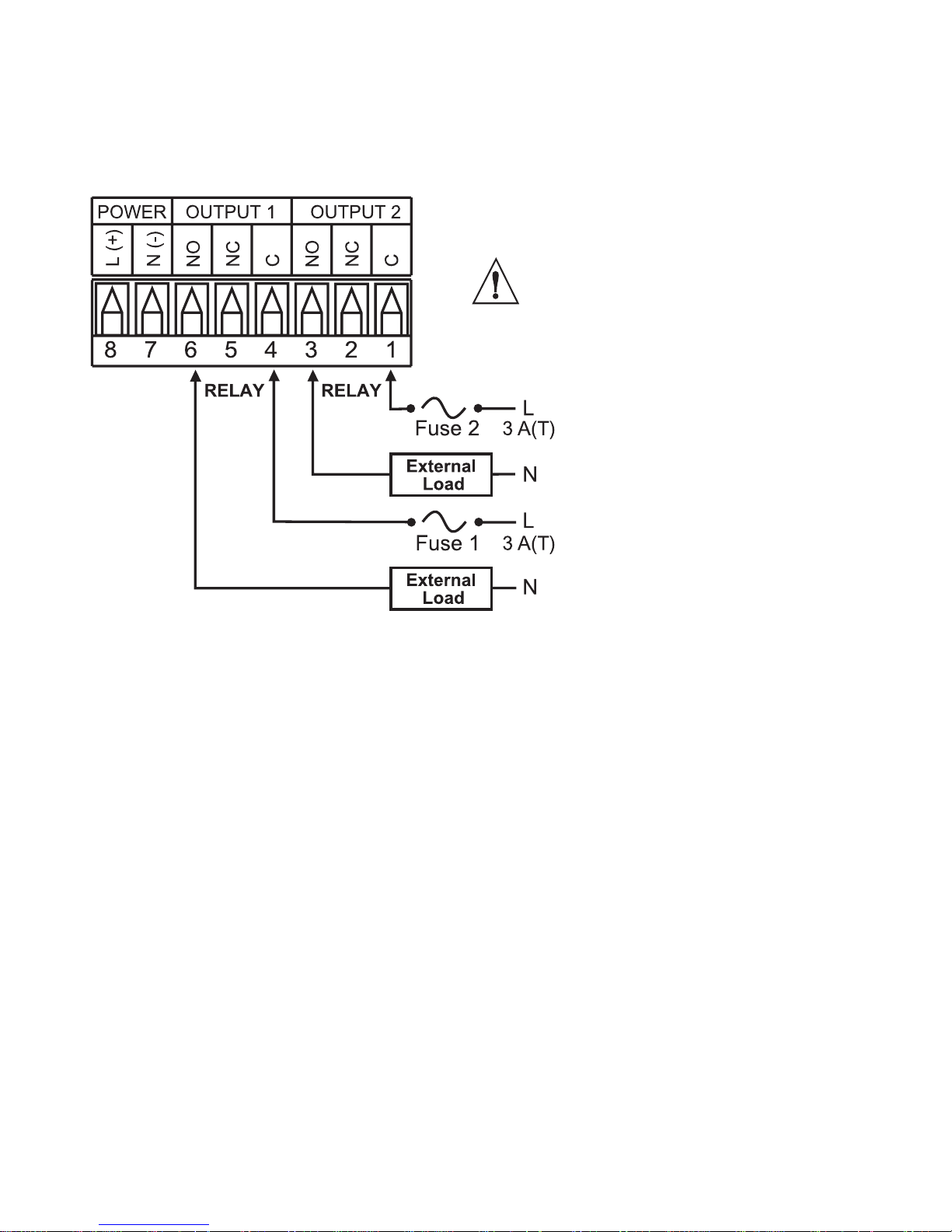
2.3.6 Wiring Outputs
This device has two factory installed outputs.
The SPDT Mechanical Relay Connection is shown below.
Use copper conductors
only for power connections
Figure 2.9 Mechanical Relay Output Wiring Hookup
10

PART 3
OPERATION: Conguration Mode
3.1 Introduction
The device has two different modes of operation.
The rst, Run Mode, is used to display values for the Process Variable,
and to display or clear Peak and Valley values.
The other mode, Menu Conguration Mode, is used to navigate through
the menu options and congure the device.
Part 3 of this manual will explain the Menu Conguration Mode. For your
device to operate properly, the user must rst “program” or congure the
menu options.
Turning your device On for the First Time
The device becomes active as soon as it is connected to a power
source. It has no On or Off switch.
The device at first momentarily shows the software version number,
followed by reset
, and then proceeds to the Run Mode.
RST
11
 Loading...