

Page 1

Newport Medical Instruments, Inc.
Newport HT70 Ventilator
Operating Manual
for Plus Model
OPRHT70-2 Rev. F
06/13
0344
Newport Medical Instruments, Inc.
1620 Sunower Ave.
Costa Mesa, CA 92626
Tel: 1.714.427.5811
Tel: 1.800.451.3111 (USA Only)
Fax: 1.714.427.0489
Customer Service ext. 282
www.ventilators.com
email: Info@ventilators.com
Page 2

Page 3

5
OPR360U A0509
5-1
Manual Revision History
HT70 Operating Manual OPRHT70-2
Revisions Date Description
Rev A October 2011 New release
Rev B November 2011 Miscellaneous type corrections,
text change on page 3-3, 7-1, 7-3
regarding Power Pac.
Rev C May 2012 Add Operating Manual Reivison.
Notice regarding the following
change: Pulse Oximeter accessory
and related functions no longer
available.
Rev D July 2012 Software update ver. P05.12.10
and above, Remove references
to optional Pulse Oximeter (not
available), Change Slope/Rise
setting was: 1 is fastest, is: 1 is
slowest.
Rev E November 2012 Update to correct image reversal
in F-1 and F-2, callout labels on
various drawings converted to
numbers and referenced in text or
added to table. Remove reference
to Aequitron nurse call systems.
Replace warranty details with who
to contact information.
Rev F June 2013
Add information about the
Aequitron Remote Alarm System.
OPRHT70-2 F0613
Page 4

Page 5

5
OPR360U A0509
5-1
Contact Information
Thank you for using the Newport HT70 family of ventilators. With
the HT70 you not only get a great ventilator, you get the support
of Newport Medical. Since 1981 we have maintained a focused
commitment to the design, production and sale of ventilators. We
have dedicated our efforts to providing ventilators that are easy to
use, clinically versatile, and cost effective.
We know that ventilatory support is critical in emergency and critical
care situations. But for many of our customers, it is also a part of
their daily lifestyle. The HT70 Ventilators offer home care users the
expanded mobility that allows them to experience more freedom in
their lives than many have ever known before.
We have designed this manual to be comprehensive and still very
user friendly. For the best performance from your HT70 Ventilator,
please take the time to review this manual completely.
See our contact information on the following page for complete
details.
OPRHT70-2 F0613
Page 6

Page 7

5
OPR360U A0509
Contact Information
Contact Information
Telephone:
+1.714.427.5811
1.800.451.3111 (US only)
Fax:
+1.714.427.0489
Departments:
Customer Service (Ext. 282)
Technical Services (Ext. 500) available 24/7
Clinical Support (Ext. 123) available 24/7
Operational Hours:
Days: Monday through Friday
Hours: 8:00 am to 5:00 pm (PST)
Emergency After-hours: 24-Hour Clinical and Technical Support
Email:
Customer Service: customers@ventilators.com
Clinical Education and Support: clinical@ventilators.com
Technical Education and Support: techservice@ventilators.com
Internet:
www.ventilators.com
Shipping Address:
Newport Medical Instruments
Attn: Receiving Department
1620 Sunower Avenue
Costa Mesa, CA 92626, USA
EC REP
Authorized European Representative
Emergo Europe
Molenstraat 15
2513 BH, The Hague
The Netherlands
OPRHT70-2 F0613
Page 8

Page 9

FOLDOUT DRAWINGS
Use the following drawings as reference while reviewing
the manual sections
Unfold to view drawing on reverse side
OPRHT70-2 F0613
Page 10
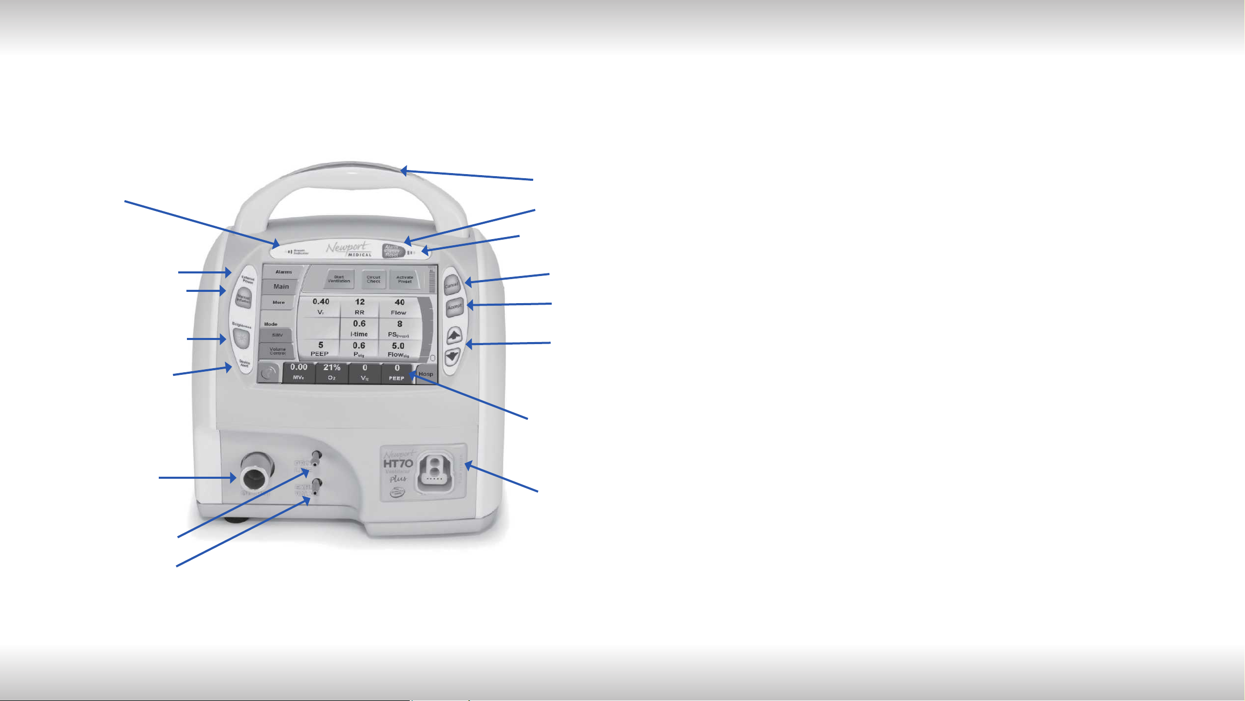
Figure F-1 English Version- Front Panel Overview
1
9
10
1. Breath Delivery Indicator LED. Flashes green with every breath delivered by the
ventilator.
2. External Power LED. Lights green whenever external power is connected. This
also indicates that the Internal Dual Battery System is being charged.
3. Manual Inflation button. Press and hold this button to deliver ow to the patient.
The ventilator will deliver ow at the current settings while the button is pressed.
Flow delivery is limited to a maximum of 3 seconds or until the High Pressure
alarm setting is reached.
11
2
3
4
5
6
12
13
14
15
16
4. Brightness button. Press this button repeatedly to scroll to one of four screen
brightness levels.
5. Device Alert LED. Lights red when there is a device alarm. Take the ventilator out
of service and use an alternate means of ventilation until resolved.
6. Patient Gas Output. Attach patient breathing circuit tubing here.
7. Proximal Pressure Line connector. Attach proximal pressure tubing here.
8. Exhalation Valve Drive Tubing connector. Attach exhalation valve drive tubing here.
9. Alarm Violation LEDs. LEDs in the handle light to indicate alarm conditions.
10. Alarm Silence/Reset button. Press this button to silence the audible alarm for 1
minute. Once an alarm condition has been corrected, press this button to clear/
reset the alarm message and latched indicators.
11. Alarm Silence LED. Remains lit during the one minute alarm silence period.
12. Cancel button. Press this button if you want to cancel changes that have not
already been accepted.
13. Accept button. Press this button to accept/conrm all changes made to control
settings.
F-1
14. s Up / t Down Arrow buttons. Press to change a highlighted parameter up/down
7
8
by one unit. Hold down continuously and the parameter will change at an increasingly
quicker pace.
15. Touch Screen User Interface. Touch screen to access alarms and parameter settings.
16. Flow Sensor connector. Attach on-airway ow sensor here.
OPRHT70-2 F0613
Page 11
Unfold to view drawing on reverse side
OPRHT70-2 F0613
Page 12
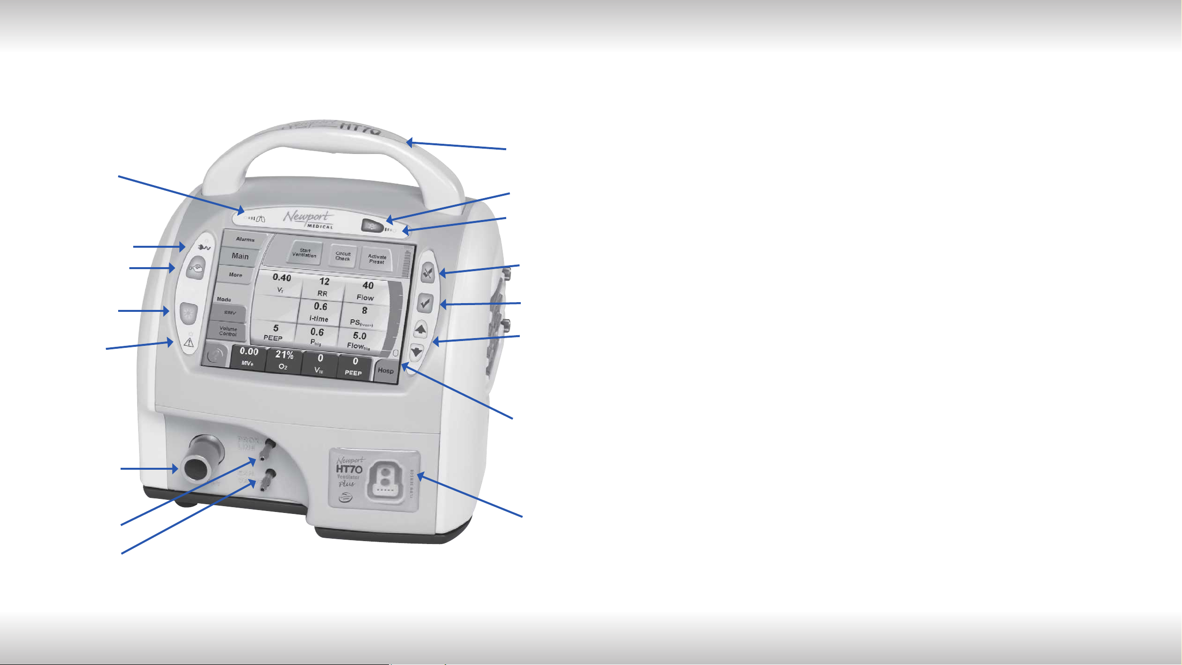
Figure F-2 Symbols Version- Front Panel Overview
1
9
10
1. Breath Delivery Indicator LED. Flashes green with every breath delivered by the
ventilator.
2. External Power LED. Lights green whenever external power is connected. This
also indicates that the Internal Dual Battery System is being charged.
3. Manual Inflation button. Press and hold this button to deliver ow to the patient.
The ventilator will deliver ow at the current settings while the button is pressed.
Flow delivery is limited to a maximum of 3 seconds or until the High Pressure
alarm setting is reached.
5
4
6
3
2
11
15
12
13
14
4. Brightness button. Press this button repeatedly to scroll to one of four screen
brightness levels.
5. Device Alert LED. Lights red when there is a device alarm. Take the ventilator out
of service and use an alternate means of ventilation until resolved.
6. Patient Gas Output. Attach patient breathing circuit tubing here.
7. Proximal Pressure Line connector. Attach proximal pressure tubing here.
8. Exhalation Valve Drive Tubing connector. Attach exhalation valve drive tubing here.
9. Alarm Violation LEDs. LEDs in the handle light to indicate alarm conditions.
10. Alarm Silence/Reset button. Press this button to silence the audible alarm for 1
minute. Once an alarm condition has been corrected, press this button to clear/
reset the alarm message and latched indicators.
11. Alarm Silence LED. Remains lit during the one minute alarm silence period.
12. Cancel button. Press this button if you want to cancel changes that have not
already been accepted.
13. Accept button. Press this button to accept/conrm all changes made to control
settings.
F-2
14. s Up / t Down Arrow buttons. Press to change a highlighted parameter up/down
7
16
8
by one unit. Hold down continuously and the parameter will change at an increasingly
quicker pace.
15. Touch Screen User Interface. Touch screen to access alarms and parameter settings.
16. Flow Sensor connector. Attach on-airway ow sensor here.
OPRHT70-2 F0613
Page 13
Unfold to view drawing on reverse side
OPRHT70-2 F0613
Page 14
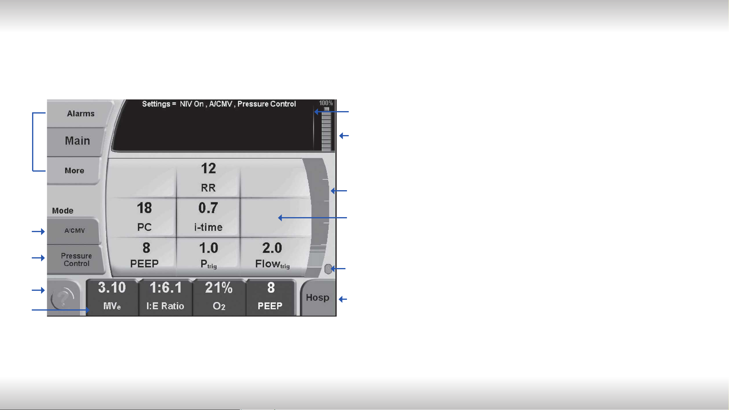
Figure F-3 HT70 Plus Model Touch Screen (Hospital Domain)
1
1. Screen Selections buttons. Touching any one of these buttons will take you to the new
screen. The More screen includes links to Event, Trends, Wave and Utility screens.
2. Mode selector. Touching this button scrolls through the mode choices. The mode will
not change until you press the Accept button.
3. Breath Type selector. Touching this button toggles the breath type choice. The breath
type will not change until you press the Accept button.
4. Help button. Touching this button enables a tutorial for each feature on the screen.
6
7
8
9
Touch the help button then touch any button for an explanation of that feature.
5. Monitored Data buttons. Touching any one of these four buttons opens a screen with a
view of monitored parameter choices to display in that button.
6. Message display. This area shows all informational and alarm messages and current
NIV selection, mode, and breath type selection. During an alarm violation this area will
light red for High Priority, amber for Medium Priority and yellow for Low Priority alarms
and display the alarm message.
7. Battery Charge Level indicator. Shows the charge level of the “Power Pac” battery
pack (blue icon) during external power or Power Pac use or the charge level of the
Backup Battery (red icon) during Backup Battery use.
8. Pressure Bar. Indicates dynamic pressure in the patient circuit in green, the High and
Low Pressure Alarm settings in red and the peak pressure of the last breath in green.
2
3
4
5
F-3
10
11/12
9. Parameter Setting buttons. Touching any one of these buttons will activate the
parameter to allow adjustments.
10. Patient Effort indicator. Flashes green to show a spontaneous patient effort.
11. Domain button. The HT70 can be set up in one of three Domains: Basic, Transport and
Hospital. Touch to scroll through the Domain choices. Press Accept to conrm choice.
12. AutoLock/Unlock button. This button is only visible if Auto Lock is enabled and the
panel is locked. Touch and hold for 3 seconds to unlock touch screen buttons.
NOTE: While operating on battery power with Power Save enabled and all alarms cleared, the
touch screen will go to sleep after 2 minutes. Just touch the screen to bring it back into view.
OPRHT70-2 F0613
Page 15

OPR360U A0509
5-1
5
Table of Contents
1 Introduction
Brief Device Description ............................................................. 1-1
Intended Use .............................................................................. 1-3
Warnings, Cautions and Notes ................................................... 1-3
2 Overview of Controls, Screens and Connectors
Front Panel Overview ................................................................. 2-1
Touch Screens Overview ............................................................ 2-1
Internal Dual Battery System Overview ...................................... 2-1
Rear Panel Overview .................................................................. 2-2
Right Side Overview ................................................................... 2-3
Left Side Overview ..................................................................... 2-3
Bottom Panel Labeling ............................................................... 2-4
3 Set up and Pre-use Preparations
Unpack the HT70 Ventilator ........................................................ 3-1
Assemble the Ventilator .............................................................. 3-2
Connect to AC Power ................................................................. 3-2
Using the Power Switch ............................................................. 3-3
Make Parameter Changes .......................................................... 3-4
Attach a Patient Circuit ...............................................................3-4
For use with a third party humidier ..................................... 3-5
For use with an HME ............................................................3-8
Using the On-airway Flow Sensor ...................................... 3 -10
Connect Optional Accessories .................................................. 3 -11
Air/Oxygen Entrainment Mixer .............................................3 -11
Low Flow Oxygen Reservoir ............................................... 3 -12
D.C. Auto Lighter Power Adapter ....................................... 3-14
Aequitron Remote Alarm Cable Accessory ........................ 3 -14
4 Navigating the HT70 Screens
Touchscreen (Graphical User Interface) Layout ......................... 4-1
Primary Screen Buttons and Displays........................................ 4 -1
Ventilator Settings Adjustment ...................................................4-4
Start Up Screen Navigation (Standby Condition Only) ..............4-4
Circuit Check Button ............................................................ 4-5
How to Perform a Circuit Check ..................................... 4-5
If the Circuit Check Fails .................................................4-6
Activate Preset Button .......................................................... 4-7
How to Use a Preset ....................................................... 4-7
Start Ventilation Button .............................................................. 4-7
OPRHT70-2 F0613
Page 16

555
OPR360U A0509
5-1
Table of Contents
Alarms Screen Navigation .......................................................... 4-8
Main Screen Navigation ............................................................. 4-9
More Screen Navigation ............................................................4 -11
More Screen Details ........................................................... 4-13
Events ........................................................................... 4 -13
Trends ........................................................................... 4-14
Waves ........................................................................... 4 -15
O2 Cylinder Data Screen .............................................. 4-16
Calibrate O2 Monitor .....................................................4-17
Utility Screen ............................................................................ 4 -18
Utility Screen Details .......................................................... 4 -19
Time/Altitude Screen .................................................... 4-19
Customize Settings Screen .......................................... 4-20
Custom Presets ............................................................ 4-21
Back Up Ventilation ......................................................4-22
Domain Navigation ................................................................... 4-23
Hospital .............................................................................. 4-23
Transport ............................................................................ 4-24
Basic ................................................................................ 4-25
5 Operating the HT70 Ventilator
Quick Check Procedure ............................................................. 5-1
Introduction .......................................................................... 5-1
Equipment Needed ............................................................... 5-1
Pretest Inspection ................................................................. 5-1
Set Up .................................................................................. 5-1
Standard Test Settings ......................................................... 5-2
Quick Check Procedure ....................................................... 5-2
Pass / Fail Check Off Sheet ................................................. 5-4
Patient Setup Procedure ............................................................5-5
Troubleshooting Guide ............................................................... 5-7
6 Ventilator Alarms
Setting Alarms ............................................................................ 6-1
Alarm Quickset ..................................................................... 6-1
Alarm Indicators ......................................................................... 6-2
Alarm Silence/Reset Button .................................................6-2
Alarm Silence LED ................................................................ 6-2
User Adjustable Alarms .............................................................. 6-2
Backup Ventilation ......................................................................6-6
Automatic Alarms .......................................................................6-6
Battery Alarms ............................................................................ 6-9
OPRHT70-2 F0613
Page 17

5
5
OPR360U A0509
5-1
Table of Contents
7 Battery Operation
Internal Dual Battery System .......................................................7-1
Power Pac Battery Pack ..............................................................7-1
Backup Battery ........................................................................... 7-2
Conditions that Affect Battery Use Time .................................... 7-2
Check the Battery Charge Level and Battery Time Estimator ... 7-3
Best Use Tips ............................................................................. 7- 3
Battery System Maintenance ..................................................... 7- 4
Power Pac Battery Pack Removal .............................................. 7-4
Battery Alarms Overview ............................................................ 7-5
Power Accessories ..................................................................... 7- 6
8 Cleaning and Maintenance
Cleaning and Disinfecting ........................................................... 8 -1
Ventilator .................................................................................. 8 -1
Accessories ................................................................................ 8-2
Low Flow Oxygen Reservoir ................................................. 8-2
Air/Oxygen Entrainment Mixer .............................................. 8-2
Reusable Breathing Circuits ....................................................... 8-3
Air Intake Filter ............................................................................ 8-3
Proximal Inline Filter ...................................................................8-4
Maintenance Guidelines ............................................................. 8-4
Routine Maintenance ............................................................8-4
6 Month Maintenance ........................................................... 8-5
12 Month Maintenance ......................................................... 8-5
24 Month Maintenance ......................................................... 8-5
15,000 Hour Maintenance ....................................................8-6
General Warnings ....................................................................... 8-6
Factory Maintenance or Repair .................................................. 8-7
Repacking/Return Information ................................................... 8-7
9 Specifications
Front Panel Buttons - Symbols Version ..................................... 9-1
Miscellaneous Reference Symbols ............................................ 9-2
Controls / Monitors .....................................................................9-3
Monitor Data Selections ............................................................. 9-4
Front Panel Membrane Buttons and Indicators .........................9-4
Alarms .................................................................................. 9-5
User Adjustable .................................................................... 9-5
Automatic .............................................................................9-5
Hardware Requirements ............................................................. 9-7
Environment ................................................................................9-8
Size and Weight ..........................................................................9-8
OPRHT70-2 F0613
Page 18

5
5
OPR360U A0509
5-1
Table of Contents
Factory Default Parameters ........................................................ 9-9
Miscellaneous ............................................................................9-9
(optional) Air / Oxygen Entrainment Mixer .................................. 9-9
(optional) Low Flow Oxygen Reservoir ....................................... 9-9
Regulatory and Agency Standards .......................................... 9 -10
10 Explanations of Modes and Controls
Explanation of Modes and Controls ......................................... 10-1
Foldout Diagrams
English Version - Front Panel Overview ..................................... F-1
Symbols Version - Front Panel Overview ................................... F-2
HT70 Plus Model Touch Screen ................................................. F-3
OPRHT70-2 F0613
Page 19

Section 1:
Introduction
Introduction
Page 20

5
Page 21

5
OPR360U A0509
5-1
Section 1:
Introduction
Brief Device Description .................................... 1-1
Intended Use .......................................................1-3
Warnings, Cautions and Notes ......................... 1-4
Page 22

5
Page 23

5
OPR360U A0509
5-1
Introduction
Brief Device Description
The Newport HT70 family of ventilators are state of the art ventilators
that combine ruggedness, ease of use and clinical prociency with
exceptional mobility to provide ventilatory support for infant, pediatric
and adult patients in emergency care, transport, critical care,
subacute care and home care applications. They are also ideal for
emergency preparedness applications.
The compact, lightweight HT70 ventilator is built for hard work with a
durable polymer exterior and robust overall design that stands up to
harsh environments.
The HT70 Ventilator denes ease of use with all essential controls at
your ngertips using a simple membrane button and touch screen
combination. There are no complicated menus or difcult sequences
to follow in order to make necessary adjustments for common
operations.
A three-tiered management domain system makes it very easy
for critical caregivers to manage all controls while providing quick
access to the more essential elements in transport situations
and signicantly enhanced safety and simplicity in the homecare
environment.
1
Sophisticated Clinical Capabilities
In addition to its durability and ease of use, the HT70 ventilator offers
the complete array of clinical capabilities needed for managing
critical patients.
The twin micro-piston pump’s ability to deliver a variable ow enables
the HT70 to provide a full range of operating modes and breath types
with servo-controlled, leak-compensated PEEP. Leak compensation
helps to improve triggering and avoid auto-triggering when a leak is
present. The HT70 may be used with an endotracheal tube, tracheal
tube, face mask, nasal mask or prongs, or mouthpiece.
There are 3 models for the HT70 series of ventilators:
HT70S HT70 Basic for use when Pressure Support is not
needed.
HT70 HT70 Classic, adds Pressure Support and related
parameters and Trends screen
HT70PM HT70 Plus, adds on-airway ow sensor option with
graphics, ow trigger and exhaled volumes
The HT70 Basic and Classic models provide monitoring of inspiratory
tidal volume (every breath), inspiratory minute volume, total
respiratory rate, peak pressure, mean pressure and baseline (PEEP)
pressure. Real-time patient circuit pressure is displayed at all times
OPRHT70-2 F0613
1-1
Page 24

5
5
OPR360U A0509
5-1
1
Introduction
on the airway pressure gauge on the face panel. A comprehensive
alarm system is built-in to alert the user to violations of user-set or
ventilator safety limits. An optional built-in oxygen sensor allows
monitoring of O2 with high and low O2 alarms.
The HT70 Plus model adds an on-airway ow sensor with onscreen
graphics, exhaled tidal and minute volume monitoring/alarms, and ow
trigger. This manual describes the HT70 Plus model and will denote
features that are not available on the HT70 and HT70S models.
Gas delivery to the patient may be enriched with oxygen (0.21-1.00)
using either the optional Air Oxygen Entrainment (50 psi) Mixer or
optional Low Flow Oxygen Reservoir.
Exceptional Mobility
The ventilator’s unique design provides maximum mobility and safety
for short or long distance transport of critically ill patients and also for
patients who are going about their normal activities of daily life. This
exceptional mobility is derived from two sources: Newport’s patented,
power conserving dual-micro-piston technology which eliminates the
need for an external compressed gas source, and the Internal Dual
Battery System which allows virtually continuous use from battery
power through hot-swappable technology.
The HT70’s micro-pistons use a fraction of the power that is
consumed by turbines and blowers. This enables longer battery use
time. Our patented system also uses considerably less supplemental
oxygen than turbine or blower systems, again improving mobility for
transport or homecare use. The superior technology of our micropiston system over the turbine and blower systems allow the HT70
to ventilate safely over a wide range of environmental conditions and
altitudes.
The HT70’s twin micro-piston internal pump is made of mechanically
moving components. As with any other gas delivery system
made of moving components, it may emit a minor level of noise
during operation. This is not a malfunction and does not affect the
performance of the ventilator.
The Internal Dual Battery System consists of two independent but
coordinated lithium ion batteries, the Power Pac battery, located on
the back of the ventilator and the Backup Battery inside the ventilator.
The Internal Dual Battery System can provide up to 10 hours of
operation at standard settings when new and fully charged. This
system assures continued support during transport, daily activities or
power outages.
1-2
OPRHT70-2 F0613
Page 25

5
OPR360U A0509
5-1
Introduction
The detachable Power Pac is ‘hot-swappable’. That is, if more battery
time is needed, a depleted Power Pac can easily be removed from the
back of the HT70 and replaced with a recharged Power Pac without
interrupting ventilation. No tools are needed. The secondary Backup
Battery maintains operation without interruption when the Power Pac
is swapped out and also provides a minimum of 30 minutes of full
operation when all other power sources are depleted. The Power Pac
weighs two pounds and is charged anytime the ventilator is connected
to an external power source (AC or DC). It can also be charged
separately.
The HT70 may be operated from a variety of AC (100-240 VAC @ 50 /
60 Hz) or DC (12-24 VDC) external power sources or from the Internal
Dual Battery System. The optional DC Auto Lighter Power Adapter
accessory enables connection to an automobile-type DC outlet. Any
time the ventilator is connected to external power, both batteries in
the Internal Dual Battery System are charging, whether or not the
ventilator is in use.
Travel Certified
1
The HT70 has been tested for and meets requirements for use in
helicopter and xed wing transport and for use on commercial airlines.
Before traveling, be sure to speak with your airline representative
about their particular concerns and clear all of your equipment with
them well before your departure. The labeling that the FAA requires to
be on the ventilator is located on the bottom of the HT70.
Intended Use
Newport HT70 family of ventilators is intended to provide continuous
or intermittent positive pressure mechanical ventilatory support for the
care of individuals who require mechanical ventilation through invasive
or noninvasive interfaces.
Specically, the Newport HT70 family of ventilators is applicable
for infant, pediatric and adult patients greater than or equal to 5 kg
(11 lbs) in hospital, sub-acute, emergency department, and home
care environments as well as for transport and emergency response
applications.
NOTE:
Federal law (US) restricts sale by or on the order of a physician.
OPRHT70-2 F0613
1-3
Page 26

5
5
OPR360U A0509
5-1
1
Introduction
Ventilator Configurations
Newport Medical offers ve congurations for the 3 models in the
HT70 family of ventilators. See Table 1. In addition, the front control
panel labeling is available in various languages and regional power
cords, i.e. North American, European, etc., can be specied. See
your Newport Medical Representative for details.
Table 1
Part Number Description Distinguishing Features
HT70PM HT70 Plus
HT70M
HT70S
HT70SM
HT70
HT70, w/o
Oxygen Sensor
HT70, with
Oxygen Sensor
HT70, Basic w/o
Oxygen Sensor
HT70, Basic with
Oxygen Sensor
Full featured with Flow sensor,
graphics and built-in oxygen monitor
with alarms.
Classic features
No built-in oxygen monitor
Classic features
Includes built-in oxygen monitor with
alarms
Classic features except:
• No Pressure Support or Pressure
Support parameters
• No Trends
• No built-in oxygen monitor
Classic features except:
• No Pressure Support or Pressure
Support parameters
• No Trends
Includes built-in oxygen monitor with
alarms
Warnings, Cautions, and Notes
Please review all WARNINGS and Cautions outlined in this manual
before operating the ventilator.
Use of the product requires full understanding and strict observation
of all sections of these instructions. The equipment is only to be used
for the purposes specied under Intended Use and in conjunction
with appropriate patient observation and monitoring. Observe
all WARNINGS and Cautions that appear in this manual and on
equipment labels.
WARNING
1-4
A warning describes a condition that can cause injury.
OPRHT70-2 F0613
Page 27

5
OPR360U A0509
5-1
Introduction
1
Caution:
equipment.
NOTE:
convenient.
General Notes
The Newport HT70 has been designed to accommodate connectivity
with nurse call/monitoring systems. Because it is not possible to
anticipate every conguration of hardware and software associated
with nurse call/monitoring system, it is the user’s responsibility to
conrm proper functionality of the system when used in conjunction
with the HT70. Verication of alarms, alerts and patient data
transmissions is required. If the system performance is not as
expected, contact Newport Medical Technical Support for assistance
troubleshooting the set-up. Do not use the HT70 ventilator with a
nurse call/monitoring system until the functionality of the ventilator/
system combination has been conrmed.
General Cautions
Do not place liquids on or near the ventilator.
A caution describes a condition that can cause damage to
A note emphasizes information that is important or
Damage can occur if the HT70 is exposed to extreme temperatures.
Do not store the HT70 in areas where it may be exposed to
temperatures below -40° C (-40° F) or above 65° C (149° F).
To avoid the risk of electric shock, the ventilator should not be
opened by anyone other than an approved service provider.
General Warnings
The design of the HT70 ventilator, the Operating and Service
manuals, and the labeling on the ventilator take into consideration
that the purchase and use of the equipment is restricted to trained
professionals, and that certain inherent characteristics of the
ventilator are known to the operator. Instructions, warnings and
caution statements are therefore limited to the specics of the HT70.
This manual excludes references to various hazards which are
obvious to medical professionals and operators of this equipment
including consequences of product misuse, and potential adverse
effects in patients with abnormal conditions.
Transport of patients with the HT70 requires that medical staff
have a good working knowledge of the ventilator’s use and
problem resolution. Proper emergency backup equipment must be
immediately available during transport.
OPRHT70-2 F0613
1-5
Page 28

5
5
OPR360U A0509
5-1
1
Introduction
Product modication or misuse can be dangerous. Newport Medical
Instruments, Inc. disclaims all liability for the consequences of
product alterations or modications, as well as for the consequences
which might result from the combination of this ventilator with other
products, whether supplied by Newport or by other manufacturers,
unless such a combination has been specically endorsed by
Newport Medical. There is a risk of explosion if used in the presence
of ammable anesthetics.
A patient connected to a ventilator requires the constant attention of
trained caregivers to the patient’s condition.
Ventilator alarms are a critical element in the safety net of patient
care. It is extremely important for patient safety that caregivers
immediately identify and correct alarm violations.
Always have an alternate power source and means of ventilation
available when the ventilator is in use so that they are easy to access
in case of a mechanical or system problem.
If a fault is detected in the ventilator and its life support functions are
in doubt, immediately discontinue use; use an alternative method of
ventilation until the fault has been corrected. Contact your service
provider immediately.
Do not block the Emergency Gas Intake (on the bottom panel) or the
Fresh Gas Intake Port (on the right side panel).
Always use appropriate monitors to ensure sufcient oxygenation
and ventilation (such as a pulse oximeter and/or a capnograph) when
the HT70 Ventilator is in use on a patient.
The optional Air/Oxygen Entrainment Mixer and Low Flow Oxygen
Reservoir are designed to operate with medical grade oxygen.
Ensure that the oxygen source is not empty before and during
the use of the optional Air/Oxygen Entrainment Mixer or Low Flow
Oxygen Reservoir.
To avoid putting stress on the internal pump and compromising
gas delivery to the patient, ensure that the Air/Oxygen Entrainment
Mixer is not connected to the gas intake port on the ventilator when
performing a Circuit Check. Ensure that the oxygen supply is enabled
any time the optional Air/Oxygen Entrainment Mixer is secured in
place while ventilating.
1-6
OPRHT70-2 F0613
Page 29

5
OPR360U A0509
5-1
Introduction
Calibrated oxygen monitoring at clinically appropriate levels is
required for patient safety when supplemental oxygen is in use. The
optional built-in oxygen sensor on the HT70 allows High and Low O2
alarms to be enabled which can be used to assure proper oxygen
de livery.
Always plug the HT70 into an external power supply source whenever
it is available, even when HT70 is not in use, to keep the Internal
Dual Battery System fully charged and to ensure best battery
performance. Check battery capacity on the front panel before
detaching from external power.
When installing a replacement Power Pac during battery operation,
always ensure that the charge level LED on the replacement pack is
green, indicating 90% or higher charge level.
Always ensure that the green External Power LED lights when the
ventilator is connected to an external AC or DC power source.
To maintain grounding integrity when using AC power, only connect
to properly grounded receptacles.
1
Use only the Newport supplied AC Power Supply (p/n PWR3204P)
with the HT70 ventilator and HT70 Power Pac (p/n BAT3271A).
Always disconnect the external power supply prior to servicing.
After servicing the HT70, it must pass the Operational Verication
Procedure (OVP) before it is returned to patient use. See the HT70
Service Manual.
Do not use electrically conductive breathing circuits. Always use
clean and dry breathing circuits.
Always use a clean, dry lter in the following locations: a standard
bacteria lter on the gas output, a prox line (bacteria) lter on the
proximal pressure tubing port and an intake (bacteria) lter behind
the lter cover.
Adding attachments or other components or sub-assemblies to the
ventilator breathing circuit system can increase the patient’s work of
breathing and/or add resistance to patient exhalation.
Always ensure that the audible alarm loudness level is set at a
volume that can be heard by the caregiver. Do not use the ventilator
in an environment where audible alarms cannot be heard by the
caregivers.
OPRHT70-2 F0613
1-7
Page 30

5
5
OPR360U A0509
5-1
1
Introduction
The functioning of this machine may be adversely affected by the
operation of other medical equipment, such as high frequency
surgical(diathermy) equipment, debrillators or short-wave therapy
equipment in the vicinity.
This device has undergone EMC testing and found to be in
conformance with IEC 60601-1-2:2001 and meets the requirement of
CISPR11:2004 (Class B), IEC 61000-3-2:2006, and IEC 61000-3-3:1955
+ A1:2001 + A2:2005. These requirements are designed to provide
reasonable protection against harmful interference in a typical medical
installation, as well as in homecare environments. The equipment
generates, uses and can radiate radio frequency energy and, if not
installed and used in accordance with these instructions, may cause
harmful interference to other devices in the vicinity. However, there is
no guarantee that interference will not occur in a particular installation.
If this equipment does cause harmful interference with other devices,
which can be determined by turning the equipment off and on, the
user is encouraged to try to correct the interference by one or more of
the following measures;
• Reorient or relocate the receiving device.
• Increase the separation between the equipment.
• Connect the equipment into an outlet on a circuit different from
that to which the devices(s) is connected.
• Consult the manufacturer or eld service technician for help.
Copyright Information
© Copyright 2012 Newport Medical Instruments, Inc. All rights
reserved. Newport HT70 Ventilator is manufactured in accordance
with Newport Medical Instruments, Inc. proprietary information and is
protected under U.S. Patent # 7,654,802.
1-8
OPRHT70-2 F0613
Page 31

Section 2:
Overview
Overview
Page 32

5
Page 33

5
OPR360U A0509
5-1
Section 2:
Overview
of Controls,
Screens and
Connectors
Front Panel Overview ......................................... 2-1
Touch Screens Overview ................................... 2-1
Internal Dual Battery System Overview ........... 2-1
Rear Panel Overview ..........................................2-2
Right Side Overview ...........................................2-3
Left Side Overview .............................................2-3
Bottom Panel Labeling ......................................2-4
Page 34

Page 35

5
OPR360U A0509
5-1
Overview of Controls, Screens and Connectors
2
Front Panel Overview
Please refer to Foldout drawing F-1 at the front of the manual. The
HT70 front panel consists of easy access membrane buttons, LED
indicators and the patient connection manifold. The center touch
screen panel provides access to alarm and parameter settings. The
HT70 Plus model has the added port for connecting the on-airway
ow sensor. This manual describes the HT70 Plus full features.
Touch Screen Overview (Hospital Domain)
Please refer to Foldout drawing F-3 at the front of the manual. The
HT70 touch screen includes direct access to essential screens for
setting patient parameters and alarms. Simple menu navigation
allows access to advanced features and utility screens.
NOTE:
While operating on internal battery power, when the Power
Save feature is ON and there are no active alarms, the touch screen
will go to sleep after two minutes. Just touch the screen or any
membrane button to bring it back into view.
Internal Dual Battery System Overview
The Internal Dual Battery System can provide up to 10 hours of
operation when new and fully charged (under standard conditions
shown in Section 7) and consists of two independent but coordinated
lithium ion batteries; the hot swappable Power Pac battery and
the secondary Backup Battery. When external power is lost, the
ventilator will run on the Power Pac until the “Switching to Backup
Battery” alarm activates. The Backup Battery will then provide a
minimum of 30 minutes of emergency back up power. The Backup
Battery portion of the system also maintains operation without
interruption whenever the Power Pac is swapped out. The Power Pac
can be recharged independently from the ventilator. The Power Pac
has an LED on the bottom edge to show charge condition. Push the
button to see charge condition. Green = approximately 90% or higher
charge level, Amber = charge not completed, Red = battery depleted.
Always insert the Power Pac onto the HT70 and power it ON to verify
x arn
e ltE
o e
wrP
a
fa
lI i
lM aun
nn t o
Bi sen
r t s
g
h
ve ecD i
eA trl
1
1. Backup Battery
(inside the case)
2. Power Pac Battery
(exchangeable)
3. Release Latch
E
tx
oP wr
re na
e
l
nuaM la
fa o
tl iI nn
B
gr hi tn
e
s
s
D
e cv
eA
ei
r
tl
OPRHT70-2 F0613
3
2
2-1
Page 36

5
OPR360U A0509
5-1
2
Overview of Controls, Screens and Connectors
the actual charge level percentage (shown in the message display).
Proper care and maintenance of the Internal Dual Battery System will
ensure the longest life and best usage performance. See Section 7
for complete details on the Internal Dual Battery System.
Rear Panel Overview
1. “Power Pac” battery pack
2. External power supply input
3. Remote alarm output
4. Release latch
5. RS-232 output
with central monitoring systems.
6. Serial number label
7. On/Off power switch
ventilator On/Off.
Push to remove battery pack.
External communication port to communicate
Connects to Nurse Call systems.
Momentary switch to power the
2-2
OPRHT70-2 F0613
Page 37

5
OPR360U A0509
5-1
Overview of Controls, Screens and Connectors
2
Right Side Overview
1. Fresh Gas Intake port / Oxygen Accessories’ connection/
Optional Oxygen Accessories / Bio-filter connection
attachment of the optional Air Oxygen Entrainment Mixer, Low
Flow Oxygen Reservoir or Bio-lter.
2. Air Intake Filter cover
lter through the transparent cover.
Allows visual inspection of the air intake
Allows
Left Side Overview
1. Cooling fan cover
2. USB ports (2)
such as:
• aashdrivefordownloadingtheTrends*andEventHistory
les or uploading new software.
Protects the internal fan.
Allows the attachment of optional accessories
*not available on HT70S model
OPRHT70-2 F0613
2-3
Page 38

5
OPR360U A0509
5-1
2
Overview of Controls, Screens and Connectors
Bottom Panel Labeling
The Bottom Panel of the HT70 includes a label that contains
information regarding agency approvals and power ratings. Here you
will nd the model number and manufacturing information.
NOTE:
panel near the power switch.
The serial number for the unit is located on the lower rear
Type BF
0344
2-4
OPRHT70-2 F0613
Page 39

Section 3:
Set-up
Set-up
Page 40

5
Page 41

5
OPR360U A0509
5-1
Section 3:
Set up and
Pre-use
Preparations
Unpack the HT70 Ventilator .............................. 3-1
Assemble the Ventilator ....................................3-2
Connect to AC Power.........................................3-2
Using the Power Switch ....................................3-3
Make Parameter Changes .................................3-4
Attach a Patient Circuit .....................................3-4
For use with a third party humidifier .......... 3-5
For use with an HME .................................... 3-8
Using the On-airway Flow Sensor .............3-10
Connect Optional Accessories ....................... 3 -11
Air/Oxygen Entrainment Mixer ...................3 -11
Low Flow Oxygen Reservoir ....................... 3-12
DC Auto Lighter Power Adapter ................. 3 -14
Aequitron Remote Alarm Cable .................3-14
Page 42

5
Page 43

5
OPR360U A0509
5-1
Set up and Pre-use Preparation
Unpack the HT70 Ventilator
Remove all of the items from the shipping box and inspect each part
and component for completeness. Verify that there is no shipping
damage. To obtain information about a warranty, if any, contact
Technical Services or your local representative.
The Newport HT70 Ventilator, Plus Model assembly includes the
following parts:
1 ea. HT70PM-XX-X X Ventilator
1 ea. OPRHT70-2 Operating Manual
1 ea. PWR3204P AC Power Supply with Pinch Release
1 ea. PWRXXXX Country specic Power Cord
1 ea. HT460300 Air Intake Filter, Disposable (pkg. of 5 lters)
1 ea. HT6004701 Prox. Inline Filter, Disposable (pkg. of 5
lters)
1 ea. FLT3302P Bacteria Filter
2 ea. ------------- Adult/Ped Flow Sensor Kit (pkg. of 1)
Optional accessories:
o KIT3420A Adult/Ped Flow Sensor Kit (pkg. of 4)
o RSV3215A Low Flow Oxygen Reservoir
o MXL70A-XX-XX Air/Oxygen Entrainment Mixer
(country specic)
o FLT3209P Mixer Filter (for Air/Oxygen Entrainment
Mixer)
o ADP3203P DC Auto Lighter Power Adapter
o BAT3271A Power Pac Battery Pack with LED
o PWR3204P AC Power Supply with Pinch Release (use
to recharge extra batteries) (requires
country-specic power cord)
o PWR3207P NA-North American Style Power Cord (use
with Power Supply)
o PWR3210P UK-British Style Power Cord (use with
Power Supply)
o PWR3211P EU-Euro Style Power Cord (use with Power
Supply)
o CBL3223 Remote Alarm Cable (1/4” phone jack
connector)
o CRT3215A HT70 Cruiser Cart
o MNT3208A Single e-Cylinder Mount
o MNT3209A Dual e-Cylinder Mount
o 10104494 Aequitron Remote Alarm Cable
3
Contact Newport Medical Customer Service for more details on
available accessories.
OPRHT70-2 F0613
3-1
Page 44

5
5
OPR360U A0509
5-1
3
Set up and Pre-use Preparation
Assemble the Ventilator
1. After unpacking the ventilator, check to see that you have all
the accessories needed and check for any damage that may have
occurred during shipping.
2. Assemble the cart using the instructions provided with the cart.
3. Securely position the ventilator on the pedestal mount of the cart.
Caution:
ventilator and accessories remain secure and are not damaged.
Take care to assemble the cart correctly to assure that the
Connect to A.C. Power
The HT70 comes with an AC Power Supply that includes AC power
adapter with pinch-release power plug. The detachable AC power
cord can be ordered in country specic congurations. Only use the
approved HT70 AC Power Supply to connect the HT70 Ventilator to
AC p ower.
1. External power
supply input
2. Pinch Release
power cable
1
2
4
3
3. AC power cord
4. AC power adapter
Plug the pinch-release power plug from the AC Power adapter into
the external power supply input located on the lower left corner of
the Power Pac battery pack. Ensure that the cord is to the right of the
plug and that it locks in place securely. Plug one end of the power
cord into the adapter and the other end into a properly grounded
outlet.
To remove the AC Power Supply from the external power supply
input, gently pinch the connector to release the locking pin and then
pull the plug out.
3-2
OPRHT70-2 F0613
Page 45

5
OPR360U A0509
5-1
Set up and Pre-use Preparation
3
Pinch release power plug
Caution:
When the HT70 Ventilator is connected to external power, both batteries
in the Internal Dual Battery System are charged simultaneously.
NOTE:
ensure that both the Power Pac battery and the secondary Backup
Battery are fully charged before disconnecting from external power.
The Power Pac can also be connected to external power
independently of the ventilator. Before installation on an HT70
Ventilator, check the Battery Charge LED on the bottom edge of the
battery to ensure that the green LED is lit, indicating that the charge
level is approximately 90% or above. Insert the Power Pac onto the
HT70 and power it ON to verify the actual charge level percentage
(shown in the message display area).
Do not twist the power plug or it may be damaged.
Check the Battery Charge gauge on the touch screen to
Using the Power Switch
The momentary-type power switch
is located on the left side rear of the
ventilator along the bottom edge.
To power the ventilator On: Press
the power switch once and wait for
the startup screen to appear.
On/Off momentary
power switch
changes and perform the Circuit Check prior to ventilation.
To start ventilation, touch the ‘Start
Ventilation’ button at the top of the
screen.
To power the ventilator Off:
the power switch once. A message
appears that prompts you to ‘Press
Accept to Shutdown or Cancel to
Ignore’. Pressing the Accept
OPRHT70-2 F0613
The ventilator will be in Standby
Condition. You can make settings
Press
3-3
Page 46

5
5
OPR360U A0509
5-1
3
Set up and Pre-use Preparation
button will power off the ventilator. Pressing Cancel will return the
ventilator to its previous state. Press Alarm Silence to silence the
Shut Down alarm.
Make Parameter Changes
Most parameters are changed with a simple Touch / Adjust / Accept
method:
1. Activate the control by touching it (button will appear
highlighted).
2. Use the Up/Down s t buttons to adjust the setting.
3. Press the Accept button to accept the change.
You can make several adjustments before accepting the changes.
When you are satised with all of the changes, you can accept them
all by pressing the Accept button once. In the case of a mode and
or breath type change, select the Main Screen for view, change the
mode and/or breath type and then adjust all visible parameters prior
to pressing the Accept button.
Before you accept any change, if you want to go back to the previous
settings, simply press the Cancel button.
NOTE:
pressed within 20 seconds of the last button touched, the parameter
will revert to the original setting.
If a parameter is touched and adjusted but Accept is not
Attach a Patient Circuit
Always use a clean and dry patient circuit.
Always use an inline lter (p/n HT6004701 or equivalent) at the Prox.
Line Connector to protect the internal transducers from moisture or
other contaminants.
Always use a bacteria lter (p/n FLT3302P or equivalent) on the Gas
Output connector.
Always orient the exhalation valve for the correct ow orientation.
Valves used in a single limb circuit have arrows that point towards the
patient and valves that are used in J style or two limb circuits have
arrows that point away from the patient.
When using the on-airway ow sensor, orient it so that the blue
tubing is towards the patient.
3-4
OPRHT70-2 F0613
Page 47

5
OPR360U A0509
5-1
Set up and Pre-use Preparation
The HT70 Ventilator will perform to specication when Newport
recommended breathing circuits and exhalation valves are used.
Newport cannot guarantee the safe use of breathing circuits or
exhalation valves that are not recommended.
For use with a third party humidifier:
When using a humidier with the ventilator, be sure to follow the
manufacturer’s instructions for use.
See Figure 1:
1. Attach a bacteria lter to the Gas Output connector on the HT70.
2. Locate the short piece of 22 mm ID circuit tubing. Connect the
end that includes the prox line pressure port to the inlet port of
the humidier.
3
1. Prox Line Pressure Port
rml aA
ce
en
l
i
t
S
e
s
Re
ln
a
C ce
pcA
et
n
r
t a
Ex le
r
e
w
o
P
a
uln
a
M
in
ta
l
n
If o
se
s
nt
h
gB
i
1
2
r
S
A
G
PU U
T
O
c
ev
c
e
D i
t
r
e
l
A
X
O .
PR
E
N
LI
.X
H
E
E
V
L
A
V
T
6
5
2. Inlet port
3. Humidifier
4. Short section breathing
circuit
5. Bacteria filter
6. Gas output connector
3
4
Figure 1
OPRHT70-2 F0613
3-5
Page 48

5
5
OPR360U A0509
5-1
3
Set up and Pre-use Preparation
3. Attach the other end of the breathing circuit to the bacteria lter
on the HT70 Gas Output connector.
1. Breathing circuit
2. Outlet port
3. Humidifier
4. Pressure port
5. Prox line
6. Prox inline filter
7. Prox line connector
1
l mra
ee
A
nl c
t
Si
ese
R
ne
a lc
C
t
p
e
c
c
n
ra
e
x
Et l
r
owe
P
alM
nu
a
ioI
a
l
nf nt
sr
s
t
i
Bg neh
GAS
U UT
O T
A
ece
i
v
D
tA
r
el
ROX.P
E
I
LN
.
XHE
V L E A V
P
7
6
4
5
2
3
Figure 2
See Figure 2:
4. Locate the 22 mm ID end of the main breathing circuit. Attach this
end to the outlet port of the humidier chamber.
5. Attach the Prox Inline Filter with tubing to the Prox. Line
connector.
6. Attach one end of the prox tubing to the Prox Inline Filter.
7. Attach the other end of the prox tubing to the prox line pressure
port on the circuit tubing that is connected to the inlet port of the
humidier chamber.
3-6
OPRHT70-2 F0613
Page 49

5
OPR360U A0509
5-1
Set up and Pre-use Preparation
1. Exhalation Valve connector
mrAla
c
neSi
e
l
eeR ts
cn l
a e
C
tA
p
c
lE e axt
n
r
r
e
ow
P
a
a luM n
l nn iofI at
s
egh
n
ri tB s
eD cv
i
e
t
r
lAe
XP .RO
LINE
H
E .X
V
L E
VA
SG
A
OU PT U T
c e
2. Exhalation Valve tubing
3. Patient wye connector
4. Breathing circuit
5. Exhalation valve
3
1
5
2
4
3
Figure 3
See Figure 3:
8. Attach one end of the exhalation valve tubing (smallest clear
tubing) to the Exh. Valve connector.
9. Attach the other end of the exhalation valve tubing to the
connector on the exhalation valve at the end of the circuit.
10. Attach Flex Tube (not shown), if used, on the patient wye
connector.
11. If using the on-airway ow sensor, plug the connector into the
front panel port. Attach the ow sensor with the blue tubing
toward the patient onto the patient connection of the circuit. Use
the 15/22mm adapter supplied with the ow sensor to attach to
the patient interface as needed. Use the circuit clip supplied with
the ow sensor to secure the ow sensor lines to the main
breathing circuit tubing.
See Figure 4 for completed set up with humidier.
12. If a temperature probe is used, insert probes into ports at either
end of the tubing that connects the humidier and the patient wye
connector.
OPRHT70-2 F0613
3-7
Page 50

5
5
OPR360U A0509
5-1
3
Set up and Pre-use Preparation
Figure 4
13. Perform the Circuit Check. If the circuit includes an end cap,
use it during the rst step of the Circuit Check. See Section 4 for
instructions.
For use with an HME (artificial nose):
See Figure 5:
1. Attach a bacteria lter to the Gas Output connector on the HT70.
2. Locate the 22 mm ID end of the breathing circuit. Attach this end
to the bacteria lter.
3. Attach the HME to the patient wye connector.
4. Attach a pressure tee if the on-airway ow sensor is not used.
5. Attach Flex Tube, if used, to the patient side of the pressure tee/
or on-airway ow sensor adapter.
6. Attach the Prox Inline Filter with tubing to the Prox. Line
connector.
7. Attach one end of the prox tubing to the Prox Inline Filter.
8. Attach the other end of the prox tubing to the port located on the
wye connector (on-airway ow sensor in use) or to the pressure
tee adapter on patient side of the HME.
3-8
OPRHT70-2 F0613
Page 51

5
OPR360U A0509
5-1
Set up and Pre-use Preparation
1. Gas Output connector
ra m
l
e
A
c
n
eSil
teRse
a c lneC
c pec t
Ex rnte al
r
w
o e
P
l
an
u
a
M
tI an inol
f
n s
h est
i
Brg
i
e cv e
D
r
e
l t
A
ASG
U PT U
O T
A
X.R O
P
E
NI
L
XH.E
V L A V E
9
1
2
8
7
2. Bacteria filter
3. Breathing circuit
4. HME
5. Flex Tube (optional)
6. Pressure tee adapter
(patient side)
7. Prox line tubing
8. Prox inline filter
9. Prox Line connector
6
3
3
4 5
Figure 5
See Figure 6:
9. Attach one end of the exhalation valve tubing (smallest clear
tubing) to the Exh. Valve connector.
10. Attach the other end of the exhalation valve tubing to the
connector on the exhalation valve.
1. Breathing circuit
ml
r
a
A
nc
e
l e
i
S
R tees
cla eC
n
ce
lae
x r
E nt
ew
oP r
uaMa ln
l in nat
I of
g
Br tn si esh
G SA
O T UU P T
Ac pt
c
vDe ei
t
r
e
l
A
X
R
P .O
LINE
.
H
EX
V
V L A E
4
2. Exhalation valve
3. Exhalation tubing
4. Exhalation valve connector
3
2
OPRHT70-2 F0613
1
Figure 6
3-9
Page 52

5
5
OPR360U A0509
5-1
3
Set up and Pre-use Preparation
11. If using the on-airway ow sensor, plug the connector into the
front panel port. Attach the on-airway ow sensor with the blue
tubing toward the patient to the wye connector of the circuit. Use
the 15/22 mm adapter supplied with the on-airway ow sensor to
attach to the patient interface as needed. Use the circuit clip
supplied with the on-airway ow sensor to secure the on-airway
ow sensor lines to the main breathing circuit tubing.
See Figure 7 for completed setup for HME with ow sensor.
Figure 7
12. Perform the Circuit Check. If the circuit includes an end cap,
retain it for use in the Circuit Check. See Section 4 for
instructions.
Using the On-airway Flow Sensor
The Newport Flow Sensor is a disposable, single patient use onairway ow sensor that can be used for pediatric to adult patients.
Use the 15/22 mm adapter supplied with the on-airway ow sensor to
attach to the patient interface as needed. Use the circuit clip supplied
with the on-airway ow sensor to secure the on-airway ow sensor
lines to the main breathing circuit tubing.
Set up your patient breathing circuit as described above for the
appropriate usage (with or without humidier or HME). Plug the onairway ow sensor connector into the port on the front panel of the
HT70 Plus. Attach the on-airway ow sensor to the patient end of the
breathing circuit with the blue tubing toward the patient.
3-10
OPRHT70-2 F0613
Page 53

5
OPR360U A0509
5-1
Set up and Pre-use Preparation
When it is connected the ventilator will recognize the on-airway ow
sensor and enable these added features:
• Flowtrigger
• Exhaledvolumemonitoring
• HighTidalVolumealarm
• Highandlowexpiratoryminutevolumealarms
3
Caution:
circuit, be sure to remove the ow sensor from the circuit. This will
protect the ow sensor from medication build up.
When giving nebulizer treatments through the ventilator
Connect Optional Accessories
Connect optional accessories such as the Air/Oxygen Mixer, Low
Flow Oxygen Reservoir or Biolter, to the right side of the HT70 at the
Fresh Gas Intake Port.
For External DC Power use, connect the DC Auto Lighter Cable into
the external power supply input on the rear of the Power Pac battery
pack.
WARNING
of HT70. Use only approved accessories.
Air/Oxygen Entrainment Mixer
The Air/Oxygen Entrainment Mixer (p/n MXL70A-XX-XX) which is
used to blend atmospheric air with 50 psi medical grade oxygen,
attaches to the Fresh Gas Intake Port on the Filter Cover (right side
of the ventilator). Attach the mixer’s high pressure hose to an active
source of medical grade, 100% oxygen, before attaching the mixer
to the ventilator. The mixer should not be attached to the ventilator
before the Circuit Check is completed. Make sure that the oxygen
source gas is always on while using the mixer during ventilation.
Do not block the Fresh Gas Intake Port on the right side
(optional)
Use the mixer’s control knob to adjust oxygen enrichment of the gas
delivered to the patient circuit from 21 to 100 percent. The mixer
does not need re-adjustment when the PEEP and Bias Flow settings
or patient’s minute volume change.
Use a calibrated oxygen monitor with alarms (such as the one that is
built-in to the ventilator) to assure that the O
ventilator into the patient circuit matches the prescribed value.
2 that is delivered by the
OPRHT70-2 F0613
3-11
Page 54

5
5
OPR360U A0509
5-1
3
Set up and Pre-use Preparation
Check the mixer lter (p/n FLT3209P) at the time of setup and weekly
during use. Replace when dirty. See section 8 for instructions.
Pneumatic Requirements:
Oxygen 35-65 psig
(2.4 to 4.5 Bar)
Maximum accuracy 40-50
psiq (2.7-3.4 Bar)
Note:
must be medical grade,
Oxygen source gas
Ca elnc
Accept
GAS
TOU PUT
EXH.
VALVE
Oxygen Mixer
100% oxygen.
Low Flow Oxygen
Reservoir (optional)
The Low Flow Oxygen
Reservoir (p/n RSV3215A)
Low Flow Oxygen
Reservoir
which is used to blend
Ca eln
atmospheric air with 1-10
c
Accept
L/min of medical grade
oxygen, attaches to the
Fresh Gas Intake Port on the
GAS
TO U PU T
EXH .
VALVE
Filter Cover (right side of the
ventilator). Attach oxygen
supply tubing between the
oxygen owmeter and the small bore connector on the reservoir.
Attach the reservoir to the ventilator.
Use the oxygen owmeter to adjust oxygen enrichment of
the gas delivered to the patient circuit. When the Low Flow
Reservoir is in use, the percent of oxygen that is delivered
from the ventilator into the breathing circuit will vary,
depending on the use of Bias Flow and PEEP, the delivered
minute volume and the percent O
2 of the source gas.
3-12
OPRHT70-2 F0613
Page 55

5
OPR360U A0509
5-1
Set up and Pre-use Preparation
3
Oxygen Supply Flow vs Desired % of Oxygen
6
6
1
Min Vol i 25 Liters
2
Min Vol i 20 Liters
3
Min Vol i 15 Liters 7 Desired % of Oxygen Enrichment
4
Min Vol i 10 Liters
Oxygen Supply Flow vs Desired % of Oxygen
For Use With PEEP
2 3 4 51
7
5
Min Vol i 5 Liters
6 Oxygen Supply Flow, L/min
For Use Without PEEP
1 2 3 4 5
7
1
Min Vol i 25 Liters
2
Min Vol i 20 Liters
3
Min Vol i 15 Liters 7 Desired % of Oxygen Enrichment
4
Min Vol i 10 Liters
5
Min Vol i 5 Liters
6 Oxygen Supply Flow, L/min
Use these graphs for estimating the liter ow of supplemental oxygen
needed to attain a particular O2 percentage. Note that the rst graph
applies when PEEP is on (and NIV off) and the second graph applies
when PEEP is off. The graphs are also printed on the Instructions for
Use that are packaged with the reservoir.
To keep a constant percentage of O
adjustment when PEEP is turned on or off or the Bias Flow setting is
2, the owmeter will need re-
changed (PEEP and NIV on) or the patient’s minute volume changes.
Use a calibrated oxygen monitor with alarms (such as the one that
is built-in to the ventilator) to assure that the percentage of O
OPRHT70-2 F0613
2 that
3-13
Page 56

5
5
OPR360U A0509
5-1
3
Set up and Pre-use Preparation
is delivered by the ventilator into the patient circuit matches the
prescribed value.
Pneumatic Requirements: Oxygen 0-10 L/min
WARNING
oxygen will result in lower oxygen percentage levels than what is
printed on the graphs. Use a calibrated oxygen monitor to verify the
level of oxygen enrichment.
Using an oxygen concentrator in place of medical grade
Caution:
malfunction and damage.
DC Auto Lighter Power Adapter (optional)
The DC Auto Lighter Power Adapter (p/n ADP3203P) is used to plug
the HT70 into any vehicle’s DC power outlet (12 VDC to 16 VDC). The
external DC source of power will not only power the ventilator but
also charge both batteries in the Internal Dual Battery System.
This cable can also be used to connect the HT70 Ventilator to
other external batteries (12 VDC to 16 VDC) when combined with
an alligator clip adapter that is available from common electronics
outlets such as Radio Shack.
To use the DC Auto Lighter Power Adapter, plug the adapter’s pinchrelease power plug into the external power supply input located on
the lower left corner of the Power Pac battery pack. Ensure that the
cord is to the right of the plug and that it locks in place securely. Plug
the other end of the adapter into a vehicles autolighter power outlet
(12 VDC to 16 VDC).
To remove the DC Auto Lighter Power Adapter from the external
power supply input, gently pinch the connector to release the locking
pin and then pull the plug out.
Water in the oxygen supply can cause equipment
Aequitron Remote Alarm Cable
The Aequitron Remote Alarm Cable allows the user to connect the
HT70 Ventilator to the Aequitron 6217 remote alarm assembly.
This cable must be connected to both the nurse call and USB
output ports on the ventilator. The other end of this cable must be
connected to the original extension cable (not to the Aequitron unit
itself).
The ventilator must be congured to “Norm Close” (see Figure 4 on
page 4-18). In addition, see the General Notes regarding nurse call
connectivity on page 1-5.
Complete a self-test after the cable has been installed and at regular
intervals to ensure the Aequitron system is operating as intended. A
self-test consists of inducing an alarm and conrming the Aequitron
unit emits an audio alarm, and also conrming the audio alarm
ceases once the alarm in the ventilator has been reset.
3-14
OPRHT70-2 F0613
Page 57

Section 4:
Navigating
Navigating
Page 58

5
Page 59

5
OPR360U A0509
5-1
Section 4:
Navigating
the Screens
Touchscreen (Graphical User Interface)
Layout ............................................................ 4-1
Primary Screen Buttons and Displays ............. 4-1
Ventilator Settings Adjustment .........................4-4
Start Up Screen Navigation (Standby
Condition Only) ............................................. 4-4
Circuit Check Button .................................... 4-5
How to Perform a Circuit Check ..............4-5
If the Circuit Check Fails ..........................4-6
Activate Preset Button ................................. 4-7
How to Use a Preset .................................4-7
Start Ventilation Button ............................... 4-7
Alarms Screen Navigation .................................4-8
Main Screen Navigation ....................................4-9
More Screen Navigation .................................. 4 -11
More Screen Details ....................................4 -13
Events .......................................................4-13
Trends .......................................................4-14
Waves .......................................................4-15
O
Calibrate O
Utility Screen .................................................... 4-18
Utility Screen Details ...................................4 -19
Time/Altitude Screen ..............................4-19
Customize Settings Screen ....................4-20
Custom Presets ..................................4-21
Back Up Ventilation ............................4-22
2 Cylinder Data Screen .........................4-16
2 Monitor ...............................4-17
Page 60

5
5
OPR360U A0509
5-1
5
Domain Navigation ...........................................4-23
Hospital ........................................................ 4-23
Transport ..................................................... 4-24
Basic ............................................................ 4-25
Page 61

5
5
OPR360U A0509
5-1
Navigating the Screens
Touchscreen (Graphical User Interface) Layout
The touchcreen display is color coded so that it is very easy to
differentiate between basic ventilation settings which are green, alarm
settings which are red and monitored values which are yellow (on blue
background). The “More” and “Utility” settings are in blue.
If the power save feature is enabled, the HT70’s touch screen will go
dark if not touched for 2 minutes (while running on internal battery). To
bring it back into full view just touch the screen or a membrane button.
Primary Screen Navigation
The buttons for accessing Alarms, Main, and More screens as well as
the buttons for selecting mode and breath type are consolidated along
the left margin. Monitored values are displayed across the bottom
margin and the pressure bar graph rises and falls along the right. This
leaves plenty of room for the display in the middle of the screen.
The name of the active screen is written in larger letters than the other
two. To change to a different screen view, just touch one of the other
screen buttons. There is no need to press Accept.
4
Primary Screen Buttons and Displays
Refer to Figure 1
1/10
2
3
4 6/7
5
Figure 1
1.
Start up Screen selection buttons:
Condition there are three additional buttons in the Message
and Alerts display window. They disappear when the Start
Ventilation button is touched. See Startup Screen Navigation
on page 4-4 for a full description.
While in Standby
9
8
OPRHT70-2 F0613
4-1
Page 62

5
5
OPR360U A0509
5-1
4
Navigating the Screens
2.
buttons to open these screens in the center display area.
Simply touch the desired button and the screen changes.
You do not need to press Accept. See following pages for
details on these screens.
additional screens: Trends*, Events, Waves+ and Utility. You
can return to the Main screen from any of these screens by
touching the screen selection button labeled “Main”.
3.
type button to toggle between Volume Control and Pressure
Control. Then press Accept. Touch the mode button to scroll
through the selections A/CMV, SIMV or SPONT. Press Accept
to conrm.
4.
or button on the touch screen and the center panel displays
an explanation of the features or controls. Touch any button
except the help button again to close the tutorial.
5.
located at the bottom of the screen. To choose and change
the parameters displayed, touch any one of the buttons to
select it. The full monitoring screen appears and shows all
twelve monitored parameters. Touch the parameter that you
would like to display. That parameter will automatically
appear in the Monitor Data display button that was selected.
You can arrange these parameters in the order you want. The
Monitor screen will remain, showing the monitored
parameters, until you make an alternate selection, press a
different screen button (Alarms, Main or More) or for 2
minutes to allow you to view and check all monitored values.
The values on the monitor screen do not update while the
screen is displayed.
Screen selection buttons
NOTE:
Breath Type/Mode Selection buttons:
Help button:
Monitor Data display buttons:
From the “More” screen you can choose to view these
Touch the help button, then touch any feature
: Touch the Alarms, Main or More
Monitor Data buttons are
Touch the breath
NOTE:
Accept to complete your change.
6.
is determined by the Domain selection. The HT70 user
interface can be setup in one of three Domains: Basic,
Transport and Hospital. The Basic Domain is a simplied
screen for use in the longterm care or homecare setting.
The Transport Domain is an specically designed to assist
4-2
For monitor display selections, you do not have to push
Domain button:
The level of accessibility for HT70 controls
*not available in the HT70S models
+only available in the HT70 Plus models
OPRHT70-2 F0613
Page 63

5
OPR360U A0509
5-1
Navigating the Screens
during transport applications. The Hospital and Transport
Domains provide full access to all ventilation and alarm
settings as well as to the special screens and menus. Full
access is recommended for use in acute care settings and
for the initial setup of patients in long term care before
switching to Basic Domain. See Domain Navigation on pg
4-23 for more details.
7.
the Utility screen. When Auto Lock is enabled, the
touchscreen will automatically lock 20 seconds after the last
button was touched. When this occurs, a lock icon will
appear in the lower right corner in place of the Domain
button. To unlock the screen, simply touch and hold the lock
icon for 3 seconds. The screen will automatically relock when
no buttons have been touched for 20 seconds.
8.
It indicates dynamic pressure in the patient circuit with a
green bar that rises and falls. The High and Low Pressure
Alarm settings are indicated with red lines and the peak
pressure of the last breath is indicated with a green line.
Auto Lock button:
Pressure Bar:
The pressure bar appears on every screen.
The Auto Lock function is enabled from
4
9.
Battery Charge Level display:
the upper right corner of the screen. This icon indicates the
percent of charge level of the battery that is currently
operating the ventilator - either the Power Pac battery pack
(blue icon) or the Backup Battery (red icon).
10.
are three startup buttons that appear in this area. They
disappear when the ventilator is in ventilating condition. While
in Standby or while ventilating, messages, including alarm
alerts, are displayed in the message display area of the screen
in order of priority. Active alarms are displayed rst followed
by latched alarms that have not been cleared by the user.
Reset button (located on the top of the panel). As you clear
each alarm message, the alarm message with the next priority
will appear in the message display area. Continue pressing to
clear all alarm messages. Press and hold for 3 seconds to
clear all at once.
Messages and Alerts display:
NOTE:
To clear alarm messages, press the Alarm Silence
A battery icon is displayed in
In Standby Condition there
OPRHT70-2 F0613
4-3
Page 64

5
5
OPR360U A0509
5-1
4
Navigating the Screens
Ventilator Settings Adjustment
Most ventilator settings are changed by touching a parameter to
highlight it, using the up and down arrows to change the set value,
and then pressing Accept to conrm the change. Pressing and
holding the arrow button makes the change happen more rapidly.
Other parameters are changed by toggling, meaning that the same
button is touched repeatedly to change the value, then conrmed by
pressing Accept. In either case, you can press the Accept button
after each setting change or make multiple changes and then press
Accept.
If you decide not to make the changes you started, press the Cancel
button instead of pressing Accept or just wait and the values will
revert back to the original settings.
The mode and mandatory breath type selections determine which
Main Screen breath delivery parameters are active and available for
adjustment. Follow these steps when setting up ventilation:
1. While the Main screen is in view, start by selecting the mode
and mandatory breath type along the left margin of the
screen.
2. Adjust all Main screen parameters that are visible.
3. Press the Accept button to implement the mode/breath type
and relevant parameters change.
4. Visit the More screen to turn NIV ON or OFF.
5. When NIV is turned ON while PEEP is in use, the Bias Flow
adjustment window appears so that you can also adjust Bias
Flow.
6. Adjust the other relevant ventilation parameters on the More
screen.
7. Visit the Alarm screen to adjust/check alarm parameters.
Startup Screen Navigation (Standby Condition only)
When the HT70 is turned On, it goes through a short self-test before
entering the Standby Condition. Make sure that you hear the alarm
sound and see the LEDs light during the short self-test. While in
Standby, the Startup Screen is available. In addition, ventilator
settings can be adjusted. The Startup screen includes three buttons
in the top message area: Start Ventilation, Circuit Check and Activate
Presets.
4-4
OPRHT70-2 F0613
Page 65

5
OPR360U A0509
5-1
Navigating the Screens
4
Startup Screen
Circuit Check Button
Perform a Circuit Check each time the breathing circuit or exhalation
valve is replaced. While the ventilator is in Standby Condition, touch
the Circuit Check button and follow the instructions on the screen.
It is a simple two-step automated process. The Circuit Check is not
available during ventilation.
How to perform a Circuit Check
1. Touch the Circuit Check button at the top of the touchscreen and
follow the on-screen instructions.
2. For Step 1, occlude the patient connection end of the circuit. (Do
not use a test lung.)
3. Press the Accept button to conrm and start the Circuit Check.
OPRHT70-2 F0613
4-5
Page 66

5
5
OPR360U A0509
5-1
4
Navigating the Screens
4. For Step 2, open the patient connection end of the patient circuit.
5. Press the Accept button to continue the Circuit Check.
6. If the test passes, the message “Circuit Check PASSED Press
Accept to Conrm” will be displayed.
7. When the Circuit Check is completed, adjust patient settings as
needed and touch the Start Ventilation button when you are ready
to begin ventilation.
8. To cancel the Circuit Check and return to the Startup Screen,
press the Cancel button.
If the Circuit Check fails:
o The message “Circuit Check FAILED Press Accept to
Continue” will be displayed.
o Press the Accept button to return to Startup Screen.
o Check that all breathing circuit connections are properly
connected and leak free.
o Verify that the Air Oxygen Entrainment Mixer is not attached to
the Fresh Gas Intake port.
o Then touch the Circuit Check button to redo the test.
If the Circuit Check fails repeatedly, try a different circuit.
WARNING
ventilation may result. Use an alternate method of ventilation. Contact
Newport Medical Technical Support.
NOTE:
retained after power down.
4-6
Do not use the HT70 if the Circuit Check fails, inadequate
The Circuit Check results are logged into the Event History and
OPRHT70-2 F0613
Page 67

5
OPR360U A0509
5-1
Navigating the Screens
Activate Preset Button
4
While in Standby, ventilation and alarm settings can be adjusted
manually or they may be adjusted using custom or default preprogrammed parameter sets (presets) for Adult, Pediatric and Infant
patients. From the Activate Preset screen you can also touch the
New Patient Flag button to enter a “New Patient” ag in the Events
History log. You must be in Standby Condition to activate a preset or
enter a new patient ag.
How to Use a “Preset”
1. Touch the Activate Preset button.
2. Touch one of the six preset buttons that appear on the
screen. Default Preset settings are based on factory set
defaults. Custom Preset settings must be established by
the user.
3. Press the Accept button to implement the settings.
NOTE:
Alarms buttons and adjust ventilation and alarm parameters.
To establish custom parameters for a preset you must rst set all
parameters and alarms as you want them for your patient. Then go
to the More/Utility/Custom Settings/Set Custom Preset to select
a custom preset button. For instructions on how to customize the
Custom Patient Presets see page 4-20.
Start Ventilation button
Touch the Start Ventilation button to exit the Standby Condition and
begin ventilation.
NOTE:
the HT70 for the rst time.
WARNING
prior to starting ventilation. Note that during Standby Condition the
OPRHT70-2 F0613
If you do not want to use a Preset, press the Main, More and
Be sure to review all sections of this manual before you use
Ensure that all settings are appropriate for the patient
4-7
Page 68

5
5
OPR360U A0509
5-1
4
Navigating the Screens
monitored O2 is not representative of the set O2 or the O2 that will be
delivered during ventilating condition. After starting ventilation, use
a calibrated oxygen monitor (such as the one that is built-in to the
ventilator) to verify that the Air Oxygen Entrainment Mixer setting or
liter ow attached to the Low Flow Oxygen Reservoir is delivering the
prescribed O2.
Alarms Screen Navigation
(May be accessed in all Domains, Standby or Ventilating Condition
except where noted) Refer to Figure 2.
See Section 9, Specications, for ranges and more details for each
alarm and setting.
To enter Alarms Screen:
To set Alarm limits (not available in Basic Domain):
limit button to activate (highlight) it, use the up and down arrow panel
buttons to adjust the limit, then press Accept to conrm changes or
press Cancel to return to original settings. You can set multiple limits
before pressing Accept.
1.
Touch the Alarms button.
2.
Figure 2
Touch an Alarm
3.
1. Settable Alarms
#P (High Pressure) #Min Vol (High Minute Volume)
$P (Low Pressure) $Min Vol (Low Minute Volume)
#RR (High Respiratory Rate) Apnea (time adjustment)
#O2 (High O2) #VTE (High Exp. Tidal Volume)
$O2 (Low O2)
+ only available on the HT70 Plus model when the on-airway ow sensor is in use
4-8
OPRHT70-2 F0613
+
Page 69

5
OPR360U A0509
5-1
Navigating the Screens
4
2. Alarm Loudness Level 1-10 (10 is loudest)
use the up and down arrow panel buttons to adjust the loudness
level, then press Accept. Always set the alarm loudness level high
enough to ensure that caregivers will hear any alarm. If necessary
attach a remote alarm system (see Utility Screen for remote alarm
selections) to ensure that the caregiver can always hear an alarm
when it sounds.
3. Alarm Quickset
when there are no active alarms violations, Alarm Quickset will
automatically set the alarm limits. Touch this button to enter the
Alarm Quickset screen, then press Accept to activate or Cancel to
return to the Alarms screen.
When activated, Alarm Quickset monitors settings for 30 seconds
and then sets the alarms. If an alarm occurs during the monitoring
period, Quickset is canceled. During the 30 second period the touch
screen will not respond unless an alarm occurs or the Cancel button
is pressed.
Alarm Quickset will only activate when in ventilating condition.
– During Ventilating (not Standby) condition,
– Touch this button,
Main Screen Navigation
(May be accessed in all Domains, Standby or Ventilating Condition)
See Section 9, Specications, for ranges and details for all
parameters.
The ventilation parameters that are displayed on the Main Screen are
determined by the mode and breath type that are selected with the
Mode/Breath Type buttons along the left margin of the touchscreen.
Select the Mode and Breath Type rst to see the Main Screen
parameters that need adjustment.
OPRHT70-2 F0613
4-9
Page 70

5
5
OPR360U A0509
5-1
4
Navigating the Screens
Main Screen
To set ventilation parameters (not available in Basic Domain):
Touch a ventilation parameter button to activate (highlight) it, use the
up and down arrow panel buttons to adjust the setting, then press
Accept to conrm changes or press Cancel to return to original
settings. You can set multiple parameters before pressing Accept.
List of all possible ventilation parameter settings on the Main Screen
VT (Tidal Volume) RR (Respiratory Rate)
PEEP PS (Pressure Support)*
Ptrig PC (Pressure Control)
Flow (in volume control) Flow Trig
i time
+
NOTE:
Trig and Ptrig settings are active and the rst available detection of
patient effort (either ow or pressure ) will trigger a breath.
NOTE:
time are available to be set. The VT (tidal volume) is the controlling
setting. Flow and i time setting are inversely related to each other.
Changing either Flow or i time causes the inversely related setting to
be recalculated to match the new Flow or i time setting and the VT
remains steady.
For example, if you change the Flow rate to a higher setting, the
i time will decrease to meet the new Flow setting. If you change the
4-10
When an on-airway ow sensor is detected, both the Flow
For Volume Control mandatory breaths, VT, Flow and i
*not available on HT70S models
+ only available on HT70 Plus models
OPRHT70-2 F0613
Page 71

5
OPR360U A0509
5-1
Navigating the Screens
i time to a longer time period, the Flow rate will decrease to meet the
new i time setting.
Also while in Volume Control, changing the Flow waveform setting
on the More Screen will cause the Flow to change on the Main
screen. A square wave will use a lower ow and a descending ramp
waveform will use a higher ow. Always recheck the settings and
monitored values after changing the Flow waveform.
More Screen Navigation
(Hospital and Transport Domain, Standby and Ventilating Condition)
Refer to Figure 3.
See Section 9, Specications, for ranges and more details for each
parameter.
4
1. 2. 3. 4.
5. 6. 7. 8.
9.
Press the Accept button to conrm changes made to any of the
following parameters.
1. Slope Rise touch button, use up/down s t
to adjust from 1 - 10 (1 is slowest)
(Pressure Control and Pressure
Support breaths)
2. PS Exp Threshold * touch button, use up/down s t
to adjust from 5 - 85% (5% is
longest) (Pressure Support breaths)
10. 11. 12.
Figure 3
OPRHT70-2 F0613
*not available on the HT70S models
4-11
Page 72

5
5
OPR360U A0509
5-1
4
Navigating the Screens
3. PS Max i Time* touch button, use up/down s t
to adjust from 0.1 - 3.0 s (Pressure
Support breaths)
4. Flow [Square or Descending] touch button to select square or
descending ramp ow (Volume
Control breaths)
5. NIV touch button to select NIV (Non
Invasive) function ON or OFF for
all breaths
6. Bias Flow touch button, use up/down s t
to adjust from 3 to 30 L/min. Bias
Flow is delivered during exhalation
phase when PEEP is ON.
NOTE:
button, you can press Cancel at anytime to revert to previous setting.
7. O
set up oxygen cylinder content
tracking. (see page 4-16 for
details)
8. Calibrate O
screen for the internal oxygen
sensor (see page 4-17 for details)
For the above settings, if you have not pressed the Accept
2 Cylinder Data Screen touch button to access screen to
2 Monitor touch button to access calibration
9. Events touch button to access Events
screen (see page 4-13 for details)
10. Trends* touch button to access Trends
screen (see page 4-14 for details)
11. Wave s
screen (see page 4-15 for details)
12. Utility Settings touch button to access Utility
screen, see description on the
following pages
4-12
+
touch button to access Waves
*not available on the HT70S models
+only available on the HT70 Plus models
OPRHT70-2 F0613
Page 73

5
OPR360U A0509
5-1
Navigating the Screens
More Screen Details
Events Screen
(Hospital and Transport Domain, Standby and Ventilating Condition)
The Events Screen displays the last 1,000 recordable events. When
a new event occurs, the oldest event is cleared. Use the up and
down arrow panel buttons s t to scroll through the list of Events.
Recordable events include Circuit Check, parameter changes,
alarm activate/deactivate, date/time changes, alarm silenced, alarm
cleared, calibrations, screen brightness changes, new patient, and
power On/Off.
4
To record when a new patient is started, touch the ‘Activate Presets’
button while in the Startup Screen (Standby Condition) and then
press the “New Patient Flag” button. The Event History log will
record a “New Patient” entry.
As you scroll through Events, the time and parameters in use during
that Event are displayed.
NOTE:
Screen.
Date and time format selection is located on the Utility
OPRHT70-2 F0613
4-13
Page 74

5
5
OPR360U A0509
5-1
4
Navigating the Screens
Trends Screen Navigation*
(Hospital and Transport Domain, Standby and Ventilating Condition)
The Trends Screen displays trended data for monitored parameters.
Push the up and down arrow panel buttons to move the cursor to the
right or to the left.
As the cursor line moves across the graph, the time display will
indicate the time at that point on the graph and the numbers on the
line will show the value for each monitored parameter. The yellow
vertical bars represent time that the ventilator was off and not
collecting data.
There are four sets of parameters to display.
To Select a Trend Set:
To change the displayed parameters, touch the Tren ds Set button on
top of the Trends graph to scroll through these choices:
1) Peak pressure, Mean pressure and PEEP
2) Tidal Volume, Resp. Rate Total, Minute Volume
3) Peak Flow, Power Pac, Back up Batt
4) Power Pac Temp, Back up Batt Temp, Internal Temp
*not available on the HT70S models
4-14
OPRHT70-2 F0613
Page 75

5
OPR360U A0509
5-1
Navigating the Screens
To Adjust the Time Scale
You can display the trends in time frames of 1, 2, 4, 8, 24 or 72 hours.
To scroll through the time scale selections simply touch the hours
button on the top of the Trends graph.
Waves Screen
(Hospital and Transport Domain, Standby and Ventilating Condition)
+
4
The Waves Screen displays real time graphics for Pressure, Volume
and Flow. If the on-airway ow sensor is not installed, only the
pressure graph will be displayed.
Touch the ‘Choice’ button at the top of the central panel to select 1,
2 or 3 graphs for display. When only one or two graphs are chosen,
you can select which waveform you want displayed by toggling the
‘Wave’ button(s) at the top of the central panel.
Freeze.
the current waveform. The up/down arrows will move the cursor
across the waveforms and display the value for the displayed graph
at that point in time. To unfreeze, touch the same button again.
Time Scale (x-axis).
screen anywhere in the central panel. The time axis will turn yellow
and you can use the up/down arrows to increase/decrease the time
scale. Press Accept to save the new time scale.
Amplitude Scale (y-axis).
simply touch the central panel anywhere in the desired graph twice.
Touch the ‘Freeze’ button to the left of the graphs to freeze
To change the time scale simply touch the
To change the height of any waveform
OPRHT70-2 F0613
+only available on the HT70 Plus models
4-15
Page 76

5
5
OPR360U A0509
5-1
4
Navigating the Screens
The rst touch will highlight the time scale in yellow and the second
touch will highlight the y-axis. The up/down arrows can now be used
to increase/decrease the height of the y-axis. Press Accept to save
the change.
Oxygen Cylinder Data Screen
(Hospital and Transport Domain, Standby and Ventilating Condition)
Estimated cylinder use time can be displayed on the monitor screen
if the relevant cylinder data is entered, the O2 Cylinder Monitor is
Enabled, and the O2 Monitor on the Utility Screen is Enabled.
Touch More, touch O
pressure units and pressure for the cylinder you are using. Finally,
touch O2 Cylinder Monitor to Enable the function, and press Accept.
The HT70 will then calculate the estimated duration of your oxygen
supply and warn you before your cylinder may run out. Allow the
calculated display to stabilize for several minutes before starting
a transport and ensure that the estimated time is sufcient for the
planned trip or outing.
NOTE:
estimate only. It can be affected by many factors such as leaks in the
O2 path. Do not rely solely on this measurement. Check the oxygen
cylinder remaining pressure level frequently to conrm actual oxygen
consumption rate.
Size: Toggle to the size of oxygen cylinder in use: D, E, H, M, K, 100
L, & 150 L.
The oxygen cylinder use time displayed in the monitor is an
2 Cylinder Data Screen, then enter the size,
4-16
OPRHT70-2 F0613
Page 77

5
OPR360U A0509
5-1
Navigating the Screens
Units: Toggle this button to use the desired pressure units for the
oxygen cylinder (psi or ATM).
Cylinder Pressure: Touch this button and use the up/down arrows
to enter the current pressure in the oxygen cylinder (300-2450 psi or
25-175 AT M).
O
2 Cylinder Monitor: Toggle this button to ‘Enabled’ and press
accept when all data has been entered.
4
NOTE:
function to operate.
Calibrate O
(Hospital and Transport Domain, Ventilating Condition)
This screen allows the user to calibrate the internal oxygen sensor.
Either a single point or a two point calibration can be done. This can
be done while on a patient if they can tolerate the desired calibration
point (room air or 100% oxygen). Touch this button to go to the
Calibrate O2 Mon screen.
You must enable the O2 Monitor (Utility Screen) for this
2 Mon Screen
O
2 Cal, 21% O2. Touch this button and follow the onscreen
directions to calibrate at room air. Ensure that no oxygen device is
connected to the air intake port on the right side of the ventilator.
O
2 Cal, 100% O2. Touch this button and follow the onscreen
directions to calibrate at 100% oxygen. Ensure that 100% oxygen is
being delivered to the air intake port on the right side of the ventilator.
Newport suggests using the Low Flow Oxygen Reservoir with
10 L/min. of medical grade 100% oxygen connected to it.
OPRHT70-2 F0613
4-17
Page 78

5
5
OPR360U A0509
5-1
4
Navigating the Screens
Utility Screen
(Hospital and Transport Domain, Standby and Ventilating Condition
except where noted)
Refer to Figure 4
Access the Utility Screen through the More Screen as shown above.
See Section 9, Specications, for ranges and more details for each
parameter.
1. 2. 3. 4.
5. 6. 7. 8.
11.
9.
10.
12.
Figure 4
Press Accept button to conrm changes made to any of the following
parameters.
1. Auto Lock touch button to select Autolock function
Enabled or Disabled
2. Language touch button to scroll through language
selections
3. cmH
pressure units
4. Power Save touch button to select Power Save
function ON or OFF
5. Export Data only available in Standby Condition.
Touch to download data to Flash USB
Drive or computer. This is not available
while ventilating. Follow the instructions
on the screen.
6. Time/Altitude touch button to access Time and Altitude
screen (see page 4-19 for details)
2O or mbar touch button to select cmH2O or mbar
4-18
OPRHT70-2 F0613
Page 79

5
OPR360U A0509
5-1
Navigating the Screens
7. Remote Nurse Call touch button to select from Norm Open
(normally open), Norm Close (normally
closed), and Respironics nurse call
systems
For use of the Aequitron Remote Alarm
System, use Norm Close.
8. Comm touch button to select from Bernoulli
enabled, Vuelink enabled or Comm
inactive for central monitoring systems
9. Custom Settings touch button to access Backup
Ventilation (BUV) and Custom Presets
screens (see page 4-20 for details).
10. O
Enabled or Disabled
11. Software the software version installed is displayed
here
12. Hours the number of hours of ventilator
operation is displayed here
2 Monitor touch button to select to O2 Monitor
4
Utility Screen Details
Time/Altitude Screen
(Hospital and Transport Domain, Standby and Ventilating Condition)
Access the Time/Altitude Screen through the More/Utility Screens as
shown above.
OPRHT70-2 F0613
4-19
Page 80

5
5
OPR360U A0509
5-1
4
Navigating the Screens
Touch a button to activate (highlight) it, use the up and down arrow
panel buttons to adjust the setting, then press Accept to conrm
changes or press Cancel to return to original settings. You can
set multiple parameters before pressing Accept. The Hours are
displayed in military style; 1 - 12 for AM and 12 - 24 for PM.
Altitude can be displayed in meters or feet. The Altitude adjustment is
only for the accuracy of the on-airway ow sensor. If the ow sensor
is used, ensure that the altitude is set.
NOTE:
delivery in altitudes up to 15,000 feet. The patented twin micro-piston
system is a volume displacement technology that will deliver the set
volume regardless of the altitude.
Custom Settings Screen
(Hospital and Transport Domain, Standby and Ventilating Condition)
The HT70 ventilator automatically maintains accurate volume
Access the Custom Settings Screen through the More/Utility Screens
as shown above.
This screen allows access to available customization options for BUV
(Backup Ventilation) function and the Preset functions. The following
options are available on the Custom Settings Screen:
1. Set Custom Presets touch to access menu to dene the
available Custom Presets
2. BUV Settings touch to access the BUV Settings
Screen
4-20
OPRHT70-2 F0613
Page 81

5
OPR360U A0509
5-1
Navigating the Screens
4
Set Custom Presets
To store customized presets for different customized patient
protocols:
1. Turn the ventilator on.
2. Make all the changes on the ventilator that you require for
your protocol. Be sure to check the settings in the More
screen and the Alarms screen.
(from the Custom Settings Screen)
3. Once you are satised with the settings for your patient
protocol, return to the More Screen/Utility Screen/Custom
Settings screen and touch the Set Custom Presets button.
4. Touch the desired Custom Preset (infant, pediatric or adult).
5. Touch the Accept button to conrm and save your choice.
You can choose “Activate Presets” button to enable your preset
parameters from the Startup Screen (see page 4-17) in the Standby
condition.
NOTE:
Custom Presets are retained after power down.
OPRHT70-2 F0613
4-21
Page 82

5
5
OPR360U A0509
5-1
4
Navigating the Screens
BUV Settings Screen
This screen allows you to customize Backup Ventilation (BUV)
to your institution’s policies or to revert to factory default for the
Backup Ventilation parameters. You can also choose to link Backup
Ventilation to the Low Minute Volume alarm (LMV), the Apnea alarm,
or to both alarms. See Section 9, Specications, for ranges and
more details for each parameter.
(from the Custom Settings Screen)
Press Accept button to conrm changes made to any of the
parameters.
The BUV Settings Screen includes the following adjustable
parameters:
1. Minimum RR (respiratory rate)
2. Rate Factor (set rate will be multiplied times this number to
determine the BUV breath rate)
3. SPONT (mode) delta P (pressure target above set PEEP for
breath delivery)
4. SPONT (mode) i-time (i time for BUV breaths delivered while
in SPONT mode)
5. BUV Link (with LMV [low minute volume] alarm, Apnea alarm,
or both)
6. Revert to Defaults
4-22
OPRHT70-2 F0613
Page 83

5
OPR360U A0509
5-1
Navigating the Screens
Domain Navigation
The Newport HT70 is designed with the exibility of useful application
in the acute care as well as longterm care environments. To make
the product easy and safe to use in the full spectrum of applications,
we have divided care into three domains: hospital – which means
acute care, Transport – anytime the user is on the move with battery
and supplemental oxygen supplies, and Basic – for the long term/
home care environments.
Touch the Domain button in the lower right corner of the touch
screen to scroll through the domain choices, Hosp (Hospital), Trans
(Transport) and Basic (Basic). Press Accept to change to the new
domain. If the panel is locked this button is not visible until the panel
is unlocked.
Hospital Domain
4
The Hospital Domain has full access to all features and screen
selections available on the HT70. This manual describes all of the
features and screen selections found in the Hospital Domain. The
Transport and Basic Domain features and screen selections work
identically to the Hospital Domain with the limitations as noted below.
OPRHT70-2 F0613
4-23
Page 84

5
5
OPR360U A0509
5-1
4
Navigating the Screens
Transport Domain
This Domain gives preference to transport related monitoring features
like O
2 Cylinder use duration and estimated battery use time.
4-24
OPRHT70-2 F0613
Page 85

5
OPR360U A0509
5-1
Basic Domain
Navigating the Screens
4
This is a simplied screen for use in a homecare or sub-acute facility
type environment.The central parameter platform is replaced with
a digital clock unless the Main or Alarm buttons are touched. The
Breath Type and Mode settings are displayed and the user has
access to the Main and Alarm screens and can view all monitored
data by touching one of the monitor buttons at the lower margin
of the screen. The More screen is not available. No settings can
be changed within this Domain. This helps simplify operation and
protect against accidental settings changes. If a setting change is
needed or access to the More screen is required, simply use the
Domain button in the lower right corner of the screen to toggle to the
Hospital Domain. Press Accept to conrm your selection.
OPRHT70-2 F0613
4-25
Page 86

Page 87

Section 5:
Operating
Operating
Page 88

5
Page 89

5
OPR360U A0509
5-1
Section 5:
Operating
the Ventilator
Quick Check Procedure .................................... 5 -1
Introduction ................................................... 5-1
Equipment Needed ....................................... 5-1
Pretest Inspection ........................................ 5 -1
Set Up ........................................................... 5-1
Standard Test Settings ................................ 5-2
Quick Check Procedure ............................... 5-2
Pass / Fail Check Off Sheet ......................... 5-4
Patient Setup Procedure ...................................5-5
Troubleshooting Guide ......................................5 -7
Page 90

Page 91

5
OPR360U A0509
5-1
Operating the HT70 Ventilator
Quick Check Procedure
Introduction
This procedure is intended to assist qualied operators to establish
a routine program for verifying proper HT70 operation. Perform this
Quick Check procedure each time the ventilator is prepared for new
patient use. The Quick Check procedure should be performed every
6 months as part of the routine maintenance procedure to conrm
proper ventilator operation. Use a copy of the Quick Check Procedure
Check-off Sheet found at the end of this section to record the results
of each check.
HOMECARE PROVIDERS: This procedure should be performed prior
to delivery of the HT70 to a patient’s home.
5
NOTE:
when not used for two minutes. Just touch the screen anywhere to
bring it back into view.
WARNING
Equipment needed:
o 1 liter test lung with resistor (LNG800P)
o Patient breathing circuit with exhalation valve
Pre-test Inspection
1. Inspect the Air Intake Filter through the lter cover on the right
side of HT70. Replace the lter if it is dirty. See Section 8 for
replacement.
2. Examine the test lung and patient circuit to ensure that there are
no holes that will cause leaks.
3. Verify that the AC power supply is in good condition.
Set Up
1. Connect the AC power supply to an AC power source.
2. Verify that the External Power LED is lit.
3. Turn the ventilator on and verify that the audible alarm sounds
and the LEDs light during the self test.
4. Connect a breathing circuit with exhalation valve and on-airway
ow sensor if used.
5. Set the ventilator to the following Standard Test Settings and
press Start Ventilation.
If Power Save is On, the screen will go to sleep (go blank)
Do not use the HT70 if it fails the Quick Check Procedure.
Standard Test Settings
Mode A/CMV
Breath Type Volume Control
NIV Off
Tidal Volume 500 mL
i time 1.0 sec
RR 15 b/min
Ptrig 1 cmH
OPRHT70-2 F0613
2O / mbar
5-1
Page 92

5
OPR360U A0509
5-1
5
Operating the Ventilator
Flow Trig Off
$Low P Alarm 5 cmH2O / mbar
#High P Alarm 99 cmH2O / 97 mbar
$Low Min Vol alarm 0.01 L (minimum setting)
#High Min Vol alarm 50 L (maximum setting with NIV Off)
#VTE Alarm 1.00 L
PEEP/CPAP 0 cmH2O / mbar
Quick Check Procedure
1. Perform a Circuit Check
o Touch the Circuit Check button at the top of the touchscreen and
follow the on-screen instructions.
o For Step 1, occlude the patient connection end of the circuit. (Do
not use a test lung.)
o Press the Accept button to conrm and start the Circuit Check.
o For Step 2, open the patient connection end of the patient circuit.
o Press the Accept button to continue the Circuit Check.
o If the test passes, the message “Circuit Check PASSED Press
Accept to Conrm” will be displayed.
If the test fails, the message “Circuit Check FAILED Press Accept to
Continue” will be displayed.
o Press the Accept button to return to Startup Screen.
o Check that all breathing circuit components/connections are
properly connected and leak free.
o Verify that the Air Oxygen Entrainment Mixer is not
attached to the Fresh Gas Intake port.
o Then touch the Circuit Check button to redo the test.
If the Circuit Check fails repeatedly, try a different circuit.
WARNING
ventilation may result. Use an alternate method of ventilation.
Contact Newport Medical Technical Support.
o Connect the test lung to the patient connection of the circuit.
Touch Start Ventilation.
2. No External Power Alarm Check
o Disconnect the AC power supply. Verify that there is an audible
alarm and the alarm LEDs in the HT70 handle ash. Verify that the
External Power LED turns off, and the Message Area turns yellow
and displays the No External Power alarm message. Conrm that
HT70 continues to ventilate.
o Press the Alarm Silence/Reset button and conrm that its LED
lights yellow, the audible alarm is muted and the message area
returns to black.
o Press the Alarm Silence/Reset button again and conrm that the
alarm message clears.
o Reconnect the AC power supply. Verify that the External Power
LED lights green.
Do not use the HT70 if the Circuit Check fails, inadequate
5-2
OPRHT70-2 F0613
Page 93

5
OPR360U A0509
5-1
Operating the Ventilator
3. Alarms and Indicators Check
High #P Alarm
o Set the High Pressure alarm limit to 20 cmH
an audible alarm sounds and the High Pressure message displays
and that inspiration ends when pressure reaches the high limit.
Set the High Pressure alarm limit back to 99 cmH
verify that the audible alarm stops and the alarm message remains.
Press the Alarm Silence/Reset button to clear the alarm message.
Low $P Alarm
o Disconnect the test lung from the breathing circuit and verify that
after two breaths an audible alarm sounds and the Low Pressure
Alarm message displays.
o Attach the test lung to the breathing circuit and verify that the
audible alarm ceases and the alarm message remains. Press
Alarm Silence/Reset button to clear the message.
4. Pressure Gauge / PEEP Check
o Verify that the pressure gauge moves up and down with each
breath.
o Select PEEP and Peak Paw to display in each of two Monitor
Data buttons.
o Adjust PEEP to 5 cmH
displays a PEEP value of 4 to 6 cmH
o Select Pressure Control and set PC at 20 cmH
Monitor Data button displays a Peak Paw of 17 to 23 cmH
2O. Verify that the Monitor Data button
2O. Reduce PEEP to zero.
2O/mbar. Verify that
2O /mbar and
2O. Verify that the
2O.
5
5. Volume/Minute Volume/Respiratory Rate Monitor Check
o Change Breath Type back to Volume Control and conrm Tidal
Volume is set to 500.
o Select VT, Min Vol and RR Tot to display in each of three Monitor
Data buttons. Verify that VT= 450-550, Min Vol = 6-9 and RR
Tot = 13-17.
6. Power Pac Battery Pack and Backup Battery Check
o Unplug the AC power supply, clear the alarm with the Alarm
Silence/Reset button. Verify that HT70 continues to ventilate and
the Power Pac battery gauge (blue icon) reads at least 80%. If
battery charge level is not sufcient, plug into external power to
fully charge the Internal Dual Battery System.
o Remove the Power Pac battery pack. Verify that HT70 continues
to ventilate, the alarm sounds, the alarm LEDs light and the
message in the message area indicates that the Backup Battery
is in use.
o Verify that the battery gauge is now red (for secondary backup
battery) and reads at least 80%. If the secondary backup battery
charge level is not sufcient, re-insert the Power Pac battery and
plug into external power to fully charge the system.
o Replace the Power Pac battery pack and verify that the audible
alarm clears but the message remains.
o Reconnect the AC power supply into the Power Pac battery pack
and conrm that the External Power LED turns green.
OPRHT70-2 F0613
5-3
Page 94

5
OPR360U A0509
5-1
5
Operating the Ventilator
o Press the Alarm Silence/Reset button repeatedly until all alarm
messages are cleared.
7. Brightness Check
o Press the Brightness button and verify that it scrolls through 4
levels of brightness. Set the brightness at desired level.
THIS CONCLUDES THE QUICK CHECK PROCEDURE
HT70 Ventilator Quick Check Procedure
Pass / Fail Check-Off Sheet
Preparation for Use Tests Indicate result for each test
1. Circuit Check Procedure Pass _____ Fail ______
2. No External Power Alarm Check Pass _____ Fail ______
3. Alarms & Indicators Check
High
Low
#P Alarm Pass_____ Fail _____
$P Alarm Pass _____ Fail ______
4. Pressure Gauge / PEEP Check Pass _____ Fail ______
5. Volume/Minute Volume/ Pass _____ Fail ______
Respiratory Rate Monitor Check
6. Power Pac Battery Pack and Pass _____ Fail ______
Backup Battery Check
7. Brightness Check Pass _____ Fail ______
The ventilator is ready for operation when all tests have been
successfully completed.
Note any comments on inspection of unit, corrective action taken,
or recommendations for further action.
Completed by: ___________________________ Date: _________
Facility: _______________________________________________
Serial #: _______________________________________________
Unit hours: _____________________________________________
5-4
OPRHT70-2 F0613
Page 95

5
OPR360U A0509
5-1
Operating the Ventilator
Patient Set Up Procedure
5
WARNING
Section 1 prior to using the ventilator.
All ventilator controls and alarm limits must be appropriate for
the patient’s condition, according to the therapy prescribed by a
physician.
1. Press the momentary power switch located on the back of the
ventilator to turn the ventilator On. The ventilator performs a brief
self-test to ensure proper microprocessor function. During the
self-test, verify that the Startup Screen appears, the LEDs light
and the audible alarm sounds briey.
2. Ensure the ventilator, patient circuit and accessories are
assembled correctly. (See Section 3)
3. Make sure HT70 has passed the Quick Check Procedure.
4. Perform the Circuit Check. Resolve any issues. (See Section 4)
5. Set all parameters per physician’s prescription using manual
adjustment or a Custom or Default Preset. See Section 9 for
specications on all settings.
a. Select mode and breath type. Then set all parameters on
the Main Screen and relevant parameters on the More
Screen.
b. Select safe/appropriate alarm limits on the Alarms Screen.
c. Ensure that the Alarm Loudness is set loudly enough for
the alarm to be heard under all circumstances.
Review all of the General Warnings and Cautions in
6. Place a test lung on the patient end of the breathing circuit and
press the Start Ventilation button on the touchscreen.
7. Ensure that the ventilator starts operation appropriately.
NOTE:
and volume delivery for pressure breaths will be different than they
will be on the patient. Pressure Support breaths will not perform the
same way they do on patients. And PEEP may cause auto-triggering.
These differences may cause nuisance alarms during this step.
8. When you are ready, remove the test lung and attach the patient
connection of the breathing circuit to the patient interface.
9. Monitor the patient settings and check for appropriate alarm
settings.
OPRHT70-2 F0613
While ventilating a test lung, peak pressure for volume breaths
5-5
Page 96

5
OPR360U A0509
5-1
5
Operating the Ventilator
10. Verify that the patient trigger icon lights each time the patient
initiates a spontaneous breath. Re-adjust sensitivity (Ptrig or Flow
trig if using on-airway ow sensor on HT70 Plus model) as
necessary to ensure comfortable triggering without auto-
triggering. When using PEEP while ventilating a patient with an
airway leak, set NIV to ON and adjust Bias Flow to stabilize the
PEEP and eliminate auto-triggering at reasonable trigger settings.
11. Closely monitor the patient and ventilator to ensure appropriate
oxygen delivery, and adequate oxygenation and ventilation.
WARNING
ventilating patients.
WARNING
appropriately, the patient should be taken off the ventilator
immediately and connected to an alternate method of ventilation.
Contact your health care provider or physician immediately.
NOTE:
into an external power source when it is available, even when the
ventilator is not in use.
Always ensure adequate monitoring is in place when
If, at any time, the patient is not responding to ventilation
To ensure best battery performance, always plug the HT70
5-6
OPRHT70-2 F0613
Page 97

5
OPR360U A0509
5-1
Operating the Ventilator
Troubleshooting Guide for Newport HT70
Ventilation and alarm settings are determined by the physician’s
prescription. Consult with your physician on ventilation and alarm
settings.
• AlarmmessagescanbeclearedwiththeSilence/Resetbutton.
• ReviewtheentireOperatingManualforfulluserinstructions.
• Notethattheminutevolumealarmsareexpiratoryminute
volume alarms when the on-airway ow sensor is in use and
they are inspiratory minute volume alarms when the on-airway
ow sensor is not in use.
• BackupVentilationincreasestherespiratoryrateinA/CMVand
SIMV and provides pressure controlled breaths in SPONT mode.
It may be caused by the violation of a Low Minute Volume Alarm
or Apnea Alarm. Resolve the alarm to resolve the back up
ventilation.
Problem/ Area
of Concern
Touchscreen
doesn’t
respond to
touch
Touchscreen
is dark/blank
Need to view
all monitored
values
Alarm
indicator(s)
lit but not
blinking/Alarm
message in
the message
window
Water
accumulating
in the
breathing
circuit
Probable
Cause
Screen is locked
by Auto-lock
function (set on
Utilities screen)
Using Basic
Domain and
the parameters
are changed to
displays rather
than buttons
Power Save
is ON (Utility
Screen) and the
screen has “gone
to sleep” to save
power
Alarm condition
is resolved.
(Alarm is
“latched”.)
Gas is cooling as
it travels through
the circuit tubing
Touch the lock icon in the lower right
corner of the screen for 3 seconds to
unlock the screen
Touch the Basic Domain button in
the lower right corner of the screen to
toggle the domain to Hospital (Hosp),
then press Accept.
Touch the screen or push any button
to “wake up” the screen
Touch any monitored value at lower
edge of the screen
Push Silence/Reset button to clear the
indicator and messages one at a time.
Hold 3 seconds to clear all messages
at once.
Keep tubing as short and warm as
possible between the humidier and
the airway so that water remains in the
vapor state
Keep tubing away from cold surfaces
Do not aim a cooling fan at the tubing
If appropriate, use a heated wire
circuit
Resolution
5
OPRHT70-2 F0613
Water trap needs
to be emptied
Empty the water trap frequently
5-7
Page 98

5
OPR360U A0509
5-1
5
Operating the Ventilator
Problem/ Area
of Concern
Audible alarm
is too quiet
Power Pac
battery
doesn’t last
long enough
Probable
Cause
Alarm Loudness
is set too low
Not fully
recharged
Ventilator
settings/ patient
condition (a
large leak
during pressure
ventilation, a
high level of bias
ow setting, or
an aggressively
breathing
patient) demand
more gas
delivery than
the standard
settings.
Power Pac
needs to be
replaced
Resolution
Touch Alarms, touch Alarm Loudness.
Adjust setting to a higher number and
press Accept.
Connect the Power Pac to external
AC or DC power for at least 3 hours
between uses
The Power Pac battery is functioning
normally. Carry at least one extra
fully charged Power Pac battery (Part
Number: BAT3271A) for ventilator
dependent patients and for patients
whose ventilation pattern requires
higher battery power consumption.
Contact a Newport Authorized
Service Provider or Newport Medical
Technical Service Department for
assistance. Email: techservice@
ventilators.com
Tel: 1.714.4275811 Ext. 500
Check Circuit
or Prox Line
Alarm
5-8
Circuit
disconnect
Humidity in
Proximal Line
No proximal
lter in place
Inspiratory Flow
is too low, circuit
pressure does
not rise fast
enough when
the breath starts
Reconnect the circuit
Change where Proximal Line is
connected to the circuit. Move it from
the connection at the patient wye (wet
environment) to an adapter placed
directly on the inlet of the humidier
chamber(dry environment).
Insert approved proximal lter (part
number: HT6004701)
As appropriate, increase Flow or
change ow pattern in Volume
Control or speed up Slope Rise in
Pressure Control/Pressure Support.
OPRHT70-2 F0613
Page 99

5
OPR360U A0509
5-1
Operating the Ventilator
5
Problem/ Area
of Concern
Circuit Check
fails
Green “Ext
Power”
indicator on
panel does
not light
when HT70
is plugged
into external
AC (wall) or
DC (external
battery or
auto lighter
outlet) power
Probable
Cause
Leak in
breathing circuit
Connecting test
lung instead
of occluding
patient
connection of
the circuit in
step 1.
Incorrect
assembly
of circuit/
exhalation valve
Incompatible
circuit/exhalation
valve
Oxygen
connected
directly to the
circuit
Ventilator needs
service
No external
power is
reaching HT70.
HT70 is running
from the Internal
Battery System.
Resolution
Tighten all circuit & water trap
connections
Trim ends of the proximal and
exhalation valve tubings to enable a
tighter t
Check the integrity of/replace the
exhalation valve diaphragm
Remove test lung and occlude the
patient connection of the circuit
during step 1.
See Operating Manual for proper
assembly
Contact Newport Medical to verify if
circuit is compatible. Email: clinical@
ventilators.com
Use the Low Flow Oxygen Reservoir
or 50 psi Air Oxygen Mixer. Connect
oxygen devices to the Fresh Gas
Intake port after, not before, the
Circuit Check is complete
Contact a Newport Authorized
Service Provider or Newport Medical
Technical Service Department for
assistance. Email: techservice@
ventilators.com
Tel: 1.714.4275811 Ext. 500
Check power cord connections
(L-shaped pinch t connector on rear
of HT70 should angle toward the
midline of the ventilator, not away.
See diagram on sticker.)
Check that power outlet is active
External battery is depleted, plug into
another external battery, auto lighter
or AC power
Check / replace the fuse in the
External Battery System or Auto DC
Cable
Contact a Newport Authorized
Service Provider or Newport Medical
Technical Service Department for
assistance. Email: techservice@
ventilators.com
Tel: 1.714.4275811 Ext. 500
OPRHT70-2 F0613
5-9
Page 100

5
OPR360U A0509
5-1
5
Operating the Ventilator
Problem/ Area
of Concern
Autotriggering
(at a typical
trigger
setting)
(green trigger
light illuminates
when there
is no patient
effort)
In SIMV
or SPONT
modes, some
or all breaths
seem to last
extra long
Occlusion
Alarm/
Sustained
Occlusion
Alarm
The patient
will not be
ventilated.
Manually
ventilate the
patient until
this is resolved.
High (Peak)
Pressure
Alarm
This alarm
violation stops
breath delivery
until pressure
drops
Probable
Cause
Circuit and/or
airway leak
Leak is causing
ow to remain
high during
pressure
support breath
delivery, so
the PS Exp.
Threshold (ow
cycling off
threshold) is
never met
The patient’s
expiratory
gas pathway
is occluded
or partially
occluded
Coughing
/ need for
airway care or
bronchodilator
treatment
Secretions
too dry due
to inadequate
humidity
Resolution
Check for and resolve leaks if
unintentional.
If airway leak is intentional, turn on
NIV and adjust Bias Flow/Trigger
settings so that the patient can trigger
effectively without auto-triggering.
Consider using the Flow Sensor and
Flow Trigger.
Eliminate circuit leaks
Set the PS Max i-Time control to limit
the breath delivery to a reasonable
inspiratory time
Evaluate everything in the patient’s
pathway of exhalation to determine
what is causing resistance and
resolve the issue
Change HME and/or expiratory lter
if used
Change the exhalation valve
Unkink expiratory drive line
Replace ow sensor
Perform suctioning/airway care, or if
due and prescribed, give prescribed
bronchodilator treatment
Use heated humidier with
appropriate temperature setting and
keep tubing warm
5-10
Pneumatic
nebulizer inline
cont.
Contact Newport Medical for
assistance
Email: clinical@ventilators.com
Tel: 1.714.4275811 Ext. 123
cont.
OPRHT70-2 F0613
 Loading...