

Page 1

Newport Medical Instruments, Inc.
NEWPORT HT50 VENTILATOR
Service Manual
SERHT50NA Rev. A
September 2008
(P/N HT50-H, HT50-H1, HT50-H1-B)
Exclusively distributed by:
NEWPORT MEDICAL INSTRUMENTS, INC.
1620 Sunflower Avenue
Costa Mesa, CA 92626 USA
Tel: 1.714.427.5811 Ext. 500
Tel: 1.800.451.3111 (USA only)
Fax: 1.714.427.0572
Customer Service ext. 282
www.Ventilators.com
email: Info@Ventilators.com
Page 2

MANUAL REVISION HISTORY
HT50 Service Manual SERHT50NA
DATE REVISION PAGES EFFECTED
August 2008 A New release for dual
nal battery update
inter
SERHT50NA A0808
Page 3

TABLE OF CONTENTS
Section 1 . . . . . . . . . . OPERATOR’S RESPONSIBILITY
• Operator’s Responsibility for Patient Safety
• Limitation of Liability
• Warranty
• Definitions
• Typing Conventions
• Warnings and Cautions
• Factory Maintenance or Repair
• Contact Information
Section 2 . . . . . . . . . . SPECIFICATIONS
Intended Use
•
• Symbols / Labeling Table
• Controls / Alarms / Monitors
• Hardware Requirements
• Miscellaneous Specifications
• Humidifier Specifications
• Air / Oxygen Entrainment Mixer Specifications
• Oxygen Blending Bag Kit Specifications
Section 3 . . . . . . . . . . DESCRIPTION OF CONTR
ALARMS & CONNECTORS
• Front Panel Overview
• Front Panel Controls & Indicators
• Front Panel Alarms
• Front Panel Message Display Window
• Left Side Connectors
• Right Side Connectors
• Optional Accessories
• User Set Up
Section 4 . . . . . . . . . . THEORY OF OPERATION
• General System Ov
• A/CMV Mode (Assist/Control Mandatory Ventilation)
• SIMV Mode (Synchronized Intermittent Mandatory
Ventilation)
• SPONT Mode (Spontaneous Ventilation)
• P support (Pressure Support)
• Pressure Control Ventilation
• Volume Control Ventilation
• Back-Up Ventilation
erview
OLS, INDICATORS,
SERHT50NA A0808
Page 4

Section 5 . . . . . . . . . . CALIBRATION AND OPERATION VERIFICATION
• Introduction
• Test Equipment Required
• Pre-Test Inspection
• Front Panel Test / Alarm Check
• System Leak Test
• Pressure Transducer Calibration
• Pressure Meter Calibration
• Volume Factor Calibration
• Pressure Relief Valve Calibration
• Exhalation Valve Calibration
• Operational Set-Up (Standard Test Settings)
• Pressure Verification
• P trig
• PEEP / CPAP
• Pressure Control
• Exhalation Valve Sealing
• Manual Inflation
• High Paw Alarm
• Low Paw Alarm
• Check Prox Line Alarm
• Battery Test
• Humidifier (for HT50-H)
• OVP Test Record
Section 6 . . . . . . . . . . MAINTENANCE PR
• Introduction
• Tools Required
• Parts Required
• Routine Maintenance Procedure
• Annual Maintenance Procedure
• 10,000 Hour Maintenance Procedure
Section 7 . . . . . . . . . . TR
OUBLESHOOTING
• Introduction
• Mechanical and Pneumatic Troubleshooting
• Electronic Troubleshooting
OCEDURES
SERHT50NA A0808
Page 5

Section 8. . . . . . . . . . ELECTRONIC & PNEUMATIC COMPONENT REMOVAL &
REPLACEMENT PROCEDURES
• Introduction
• Tools Required
• Discharge the HT50 Power Supply
• Disassembly (Lower Case)
• Internal Battery Assembly Replacement
• Pump Assembly Replacement
• Outlet Assembly Replacement
• Humidifier Heater Assembly Replacement
• Front Panel Board Replacement
• Front Panel Bezel Replacement
• Main Board Assembly Replacement
• Power Supply Board Replacement
Section 9 . . . . . . . . . . DIAGRAMS AND PARTS LISTS
• Figure 9-1, Internal View
Figure 9-2, Final Assembly, Front View HT50-H
•
• Figure 9-3, Final Assembly, Front View HT50-H1
• Figure 9-4, Main Board with Mounting Hardware
• Figure 9-5, Main Board Tubing Connection, Left Side
• Figure 9-6, Right Side Case
• Figure 9-7, Front Panel, Side View
• Figure 9-8, Pneumatic Schematic
• Drawing Parts Reference List
Section 10 . . . . . . . . . REPACKAGING AND SHIPPING INSTRUCTIONS
Appendix A . . . . . . . . HT50 PARTS AND ACCESSORIES
SERHT50NA A0808
• Introduction
RGA (Return Goods Authorization)
•
• Packaging: Complete Unit
• Packaging: Parts or Accessories
• HT50
Ventilator Parts and Accessories
• Service Parts List
Page 6

1. OPERATOR’S RESPONSIBILITY
Operator’s Responsibility for Patient Safety . . . . . 1-1
Limitation of Liability. . . . . . . . . . . . . . . . . . . . . . . . 1-2
Warranty . . . . . . . . . . . . . . . . . . . . . . . . . . . . . . . . . 1-2
Definitions. . . . . . . . . . . . . . . . . . . . . . . . . . . . . . . . 1-3
Typing Conventions . . . . . . . . . . . . . . . . . . . . . . . . 1-3
Warnings and Cautions . . . . . . . . . . . . . . . . . . . . . 1-4
Factory Maintenance or Repair . . . . . . . . . . . . . . 1-7
Contact Information . . . . . . . . . . . . . . . . . . . . . . . . 1-8
SERHT50NA A0808
Page 7

OPERATOR’S RESPONSIBILITY FOR PATIENT SAFETY
The Operation manual (p/n OPRHT50-NA) contains information
intended to ensure safe and effective ventilator use. The label on
the inside of the front panel cover door is meant to complement not
replace the Operation manual.
The design of the HT50 ventilator, the Operating and Service
manuals, and the labeling on the ventilator take into consideration
that the purchase and use of the equipment is restricted to trained
professionals, and that certain inherent characteristics of the
ventilator are known to the operator. Instructions, warnings and
caution statements are therefore limited to the specifics of the
Newport HT50.
Caution Federal law restricts this device to sale by or on the
order of a physician.
SECTION 1
This man
ual excludes references to various hazards which are
obvious to medical professionals and operators of this equipment,
to the consequences of product misuse, and to potentially adverse
effects in patients with abnormal conditions.
When the HT50 is used in home care and sub acute environments it
is important that the primary caregiver has received training and has
demonstrated competency in all equipment functions. A specific
written care plan must be established by the attending physician.
Transport of patients with the HT50 requires that medical staff have
a good working knowledge of the ventilator’s use and problem
resolution. Proper emergency back-up equipment must be
immediately available during transport.
HT50 operators must recognize their responsibility for implementing
safety monitoring mechanisms which supply appropriate
information on equipment performance and patient condition.
Patient safety may be achieved through a wide variety of means
such as electronic surveillance of equipment performance and
patient condition. However, equipment surveillance should not
replace direct observation of clinical signs. The HT50 operator is
solely responsible for selecting the appropriate level and method of
patient monitoring.
SERHT50NA A0808 1-1
Product modification or misuse can be dangerous. Newport Medical
Instruments, Inc. (N
EWPORT) disclaims all liability for the
consequences of product alterations or modifications, as well as for
the consequences which might result from the combination of this
ventilator with other products, whether supplied by Newport or by
other manufacturers, unless such a combination has been
specifically endorsed by Newport.
Page 8

OPERATOR’S RESPONSIBILITY
LIMITATION OF LIABILITY
The liability of Newport Medical Instruments, Inc. (NEWPORT) is
subject to and limited to the exclusive terms and conditions as set
forth herein. Said liability is limited whether arising out of, or related
to, the manufacture and sale of goods, their installation,
demonstration, sales representation, use, performance, or
otherwise. Any liability based upon product warranty, whether
breach of warranty or otherwise, is limited regardless of any fault
attributable to N
breach of warranty, negligence, and strict liability).
The expressed warranties are in lieu of all other warranties,
expressed or implied, including, without limitation, warranties of
merchantability, fitness for any purpose, or noninfringement.
EWPORT shall not be liable for any special incidental or
N
consequential damages incurred by the buyer to a third party. The
buyer shall not be entitled to make liability recoveries from N
due to such situations.
EWPORT and the nature of the action (including
EWPORT
WARRANTY
The Newport HT50 Ventilator is guaranteed to be free of defects for
a period of two (2) years from date of delivery. The following are
exceptions to this warranty:
1. Defects caused by misuse, mishandling, tampering, or by
modifications not authorized by Newport Medical Instruments,
Inc. (N
EWPORT) or its representatives.
2. Rubber and plastic components and materials are guaranteed
to be free of defects at time of delivery.
3. The internal batteries are warranted for six months.
Any product which proves to be defective in workmanship or
material will be replaced, credited, or repaired. Newport retains the
discretion to select the most suitable of these options. Newport is
not responsible for deterioration, wear, or abuse. In all cases,
Newport will not be liable beyond the original selling price.
Application of this warranty is subject to the following conditions:
1-2 SERHT50NA A0808
EWPORT or its authorized representatives must be promptly
1. N
notified upon detection of the defective material or equipment.
2. Defective material or equipment must be returned to N
or its authorized representative.
EWPORT
Page 9

SECTION 1
DEFINITIONS
3. Examination b
confirm that the defect is covered by the terms of this warranty.
To ensure complete protection under this warranty, the Warranty
Registration Card must be returned to Newport within ten (10) days
of equipment receipt.
The above is the sole warranty provided by N
warranty, expressed or implied, is intended. Representatives of
Newport are not authorized to modify the terms of this warranty.
WARNING Possibility of personal injury, to patient or others, if
disregarded.
Caution Possibility of equipment damage if disregarded.
NOTE: Additional information intended to avoid inconveniences
during operation.
followed.
y NEWPORT or its authorized representatives must
EWPORT. No other
Notes also indicate important procedures to be
TYPING CONVENTIONS
Inspection: Examination of actual condition.
Service: Measures required to maintain a specified condition.
Repair: Measures required to restore a specified condition.
Maintenance: Required inspection, service, and repair of the
device.
Preventive Maintenance: Maintenance performed at regular
vals to keep the device in good working condition.
inter
Within the text of this manual, controls, alarms, and indicators are
designated by the labeling name as they appear on the ventilator,
e.g.: Psupport (pressure support), Ptrig (pressure trigger), and
SPONT (spontaneous mode).
Please review all WARNINGS and Cautions outlined in this
ual prior to servicing the HT50 for the first time.
man
SERHT50NA A0808 1-3
Page 10

OPERATOR’S RESPONSIBILITY
WARNINGS AND CAUTIONS
At all times, strictly follow this Manual.The safe use of the HT50
Ventilator requires a full understanding of its operation and
adherence to the manual’s instructions.The equipment is only to be
used for the purpose specified under “Intended Use” (see Section
2). Observe all of the WARNINGS and Cautions posted in this
man
accessories.
General Warnings
External power connection: To maintain grounding integrity when
using A.C. power, only connect to hospital grade receptacles.
Always disconnect the external power supply prior to servicing.
Always use the power cord supplied with the HT50. Make certain
the power cord ferrite is always attached to the A.C. power cord to
ensure that the HT50 meets EMC requirements.
There is a risk of explosion if used in the presence of flammable
anesthetics.
ual and on labels found on the HT50 Ventilator and associated
All settings and adjustments in the different ventilation modes must
be made in accordance with a physician’s prescribed therapy.
EWPORT cannot warrant or endorse the safe performance of third
N
party humidifiers for use with the HT50.
When the HT50 is operating on battery power, the optional built-in
humidifier does not function. A heat moisture exchanger, or other
humidification device, should be used until the unit is connected to
A.C. power at which time the built-in humidifier can be used.
Do not use electrically conductive patient circuits.
Always use a clean patient circuit.
Always use an inline filter (p/n HT6004701 or equivalent) at the
Airway Pressure Connector to protect the internal transducers from
moisture or other contaminants.
Always use appropriate monitors to ensure sufficient oxygenation
and ventilation (such as pulse oximeter and/or capnograph) when
the HT50 Ventilator is in use on a patient.
The ventilator is ready for operation only when:
a) It is completely assembled, and;
b) The Quick Check Procedure, including the Exhalation Valve
Calibration (see Appendix A, Operating Manual) or OVP
(Service Manual) has been successfully completed.
1-4 SERHT50NA A0808
Constant attention by qualified medical personnel is recommended
whenever a patient is ventilated with the HT50.
Page 11

SECTION 1
When the HT50 is used in homecare environments
, proper
education and training of the appointed caregiver must be provided
prior to the patient leaving the health care facility.
If a fault is detected in the ventilator and its life support functions
are in doubt, immediately discontinue use; use an alternative
method of ventilation until the fault has been corrected. Contact
EWPORT Technical Service Department immediately.
N
Failure to identify and correct alarm violations may result in patient
injury.
Continuous oxygen monitoring is required for patient safety. The
HT50 does not have a built-in alarm system to notify user of a failure
or disconnection of the oxygen source.
Ensure that the oxygen source is not empty before and during the
use of the optional Air/Oxygen Entrainment Mixer or Oxygen
Blending Bag Kit.
The primary internal battery should be replaced every 12 months or
sooner if the use time no longer meets the needs of the user.This
will depend on a number of factors including settings and usage
patterns. The secondary internal battery should be replaced every
24 months.
Please recognize that any life support equipment should have
appropriate alternate power sources and means of ventilation
readily available in case of a mechanical or system problem. If you
need alternative power sources, contact Newport Medical
Instruments Inc.
When the HT50 is used for transport applications, ensure that the
internal battery system is fully charged prior to use.
When the Battery Empty audible alarm sounds continuously, only a
limited time of internal battery power remains and an alternate
power source should be found immediately.
Frequent deep discharge of the internal battery system will
decrease the amount of time the HT50 will operate on battery
power from a full charge state.
If you use the internal battery system as your primary power
source, replace the primary battery as needed to ensure that the
battery operation time is sufficient.
SERHT50NA A0808 1-5
Page 12

OPERATOR’S RESPONSIBILITY
Charge the internal battery system for a minimum of 8 hours before
powering the ventilator from the internal batteries. This will provide
approximately 80% of the battery charge. If the battery system is
completely depleted, it will take approximately 10 hours to fully
recharge.
Always ensure that the green Ext. Pow er LED lights after
connecting the HT50 to an e
take up to two minutes to light). If the LED does not light, check all
power connections and resolve any problems.
Always plug the HT50 into an external power supply source when
not in use to insure best battery performance.
The flow resistance of the air inlet filter, located on the right side of
ventilator, is likely to increase with repeated use. Ensure that the
filter is changed regularly.
The HT50 Ventilator is guaranteed to perform to specification when
the Newport HT50 breathing circuit with exhalation valve is used.
See Appendix B for circuit configurations and parts list.
xternal AC or DC power source (it can
Only N
EWPORT approved exhalation valves can be used with
the HT50.
Perform an exhalation valve calibration each time a clean
circuit/exhalation valve is installed.
The functioning of this machine may be adversely affected by the
operation of equipment, such as high frequency surgical
(diathermy) equipment, defibrillators or short-wave therapy
equipment in the vicinity.
This equipment has been tested and found to comply with the EMC
limits for the Medical Device Directive 93/42/EEC (EN55011 Class
A and EN 60601-1-2). These limits are designed to provide
reasonable protection against harmful interference in a typical
medical installation. The equipment generates, uses and can
radiate radio frequency energy and, if not installed and used in
accordance with these instructions, may cause harmful interference
to other devices in the vicinity. However, there is no guarantee that
interference will not occur in a particular installation. If this
equipment does cause harmful interference with other devices,
which can be determined by turning the equipment off and on, the
user is encouraged to try to correct the interference by one or more
of the following measures:
1-6 SERHT50NA A0808
• Reorient or relocate the receiving device
• Increase the separation between the equipment
Page 13

SECTION 1
Cautions
• Connect the equipment into an outlet on a circuit diff
from that to which the devices(s) is connected
• Consult the manufacturer or field service technician for help.
Only use medical grade oxygen with the Air/Oxygen Entrainment
Mixer or Oxygen Blending Bag Kit.
Do not place liquid containers in the immediate vicinity or on top of
the HT50. Liquids that get into the ventilator can cause equipment
malfunction and damage.
After servicing an HT50, it must completely pass an Operational
Verification Procedure (see Service Manual) before being returned
to patient use.
An authorized Newport Medical Instruments factory-trained
technician must do all service or repairs performed on the HT50.
Do not open the ventilator or perform service on an open unit while
connected to external power.
erent
Use standard anti-static techniques while working inside the
ventilator or handling any electronic parts.
Clean all external parts of the ventilator prior to servicing.
Water in the oxygen supply can cause equipment malfunction and
damage.
Always replace a blown fuse with one of proper rating for
corresponding voltage range.
NOTE: Review HT50 Oper
(Section 4 of this manual) before servicing the ventilator.
NOTE: Use the tools and equipment specified in this manual to
perf
Batteries contain materials that can harm the environment. Do not
discard them in an incinerator or force them open. Batteries cannot
be disposed of with normal waste.
Factory Maintenance or Repair
ating Manual and Theory of Operation
orm specific procedures.
SERHT50NA A0808 1-7
Scheduled maintenance or repair services are available from the
Newport Technical Service Department. To send your ventilator in
for service, see HT50 Service Manual for repackaging and shipping
instructions.
Page 14

OPERATOR’S RESPONSIBILITY
Current pricing for scheduled maintenance and labor rates can be
found in Newport Medical Instruments Annual Price List. To obtain a
copy, please contact your local Newport Sales Representative or
contact our Customer Service Department using information below.
Contact Information
Address: Newport Medical Instruments, Inc.
Phone numbers: Toll-free within the United States:
Fax numbers: Main fax: 1.714.427.0489
1620 Sunflower Ave
Costa Mesa, California, USA 92626
800.451.3111
Worldwide: 1.714.427.5811
Technical Ser
Website: www.NewportNMI.com /
www
.ventilators.com
Email: Info@NewportNMI.com
Department
extensions: Customer Service: 282
T
echnical Service: 500 (24-hour pager activated
after Technical Service department hours)
Clinical Support: 123 (24-hour pager)
Corporate Office Monday through Frida
hours: (USA Pacific Time)
Technical Service Monday through Friday, 7:00 am to 4:00 pm
hours: (USA Pacific Time)
HT50s distributed internationally have CE authorization (HT50-H, HT50H1) and are represented by: Obelis, s.a. , 34 Ave de Tervuren, bte 44, B1040 Brussels, Belgium. Tel: +32.2.732.59.54 Fax:+32.2.732.60.03
email:mail@obelis.net
vice fax: 1.714.427.0572
y, 8:00 am to 5:00 pm
1-8 SERHT50NA A0808
Page 15

2. SPECIFICATIONS
Intended Use . . . . . . . . . . . . . . . . . . . . . . . . . . . . . 2-1
Symbols / Labeling Table . . . . . . . . . . . . . . . . . . . . 2-1
Controls / Alarms / Monitors . . . . . . . . . . . . . . . . . 2-2
Hardware Requirements . . . . . . . . . . . . . . . . . . . . 2-5
Miscellaneous Specifications . . . . . . . . . . . . . . . . . 2-5
Humidifier Specifications . . . . . . . . . . . . . . . . . . . . 2-7
Air / Oxygen Entrainment Mixer Specifications . . . 2-8
Oxygen Blending Bag Kit Specification . . . . . . . . . 2-8
SERHT50NA A0808
Page 16
INTENDED USE
SECTION 2
SECTION 2
This device is intended to provide continuous or intermittent mechanical
ventilator support for the care of individuals who require mechanical
ventilation. The ventilator is a restricted medical device intended for use by
qualified, trained personnel under the direction of a physician. Specifically,
the HT50 is applicable for adult and pediatric (i.e. infant, child and
adolescent) patients, greater than or equal to 10 kg or 22 lbs., who require
the following general types of ventilatory support, as prescribed by an
attending physician: positive pressure ventilation with assist/control, SIMV
and SPONT modes of ventilation. The HT50 is suitable for use in hospital,
sub-acute, emergency room, home care environments as well as for
transport and emergency response applications.
Front panel controls allow trained operators to select between a number
of operational modes, pressure support and volume or pressure control.
A comprehensive alarm system is built-in to alert the user to violations of
set safety limits. When new and fully charged, the internal battery system
provides up to 10 hours of power. With its patented, self-contained gas
supply source, the HT50 requires no external air compressor.
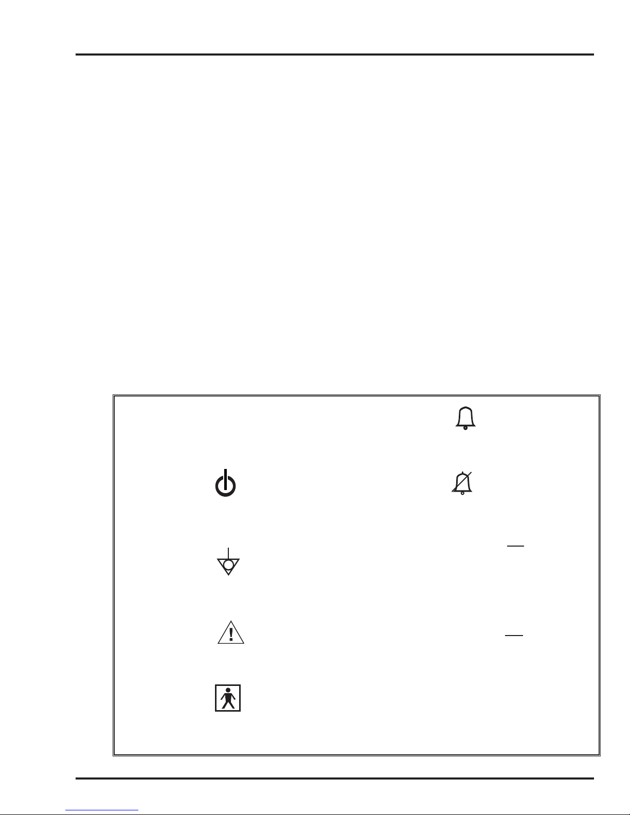
|
Main Power On
Main Power Standby
Equipotentiality
Refer to Operating Manual
Alarm Setting
Audible Alarm Silence/Reset
▲
High Alarm Set High Alarm
▼
Low Alarm Set Low Alarm
▲
▼
Applied Parts Type BF
SERHT50NA A0808 2-1
Page 17

SPECIFICATIONS
SPECIFICATIONS
SYMBOLS/LABELING TABLE
Controls/Alarms/Monitors Range/Selection
1. MODE (Pressure or A/CMV
Volume Control) SIMV
SPONT
2. Volum e C ont rol (Tidal Volume) 100 to 2,200 mL, ATPS, ± 10%
3. Pressure Control PEEP + 5 to 60 cmH
(Target Pressure)
•
4.
V
(Flow) 6 to 100 L/min
5. t
(Inspiratory Time) 0.1 to 3.0 sec
I
6. ƒ (Frequency) 1 to 99 b/min
7. P trig (Sensitivity) –9.9 to 0 cmH
O / mbar, pressure triggering
2
(Patient Effort Indicator LED blinks once each time the airway
pressure reaches the Ptrig setting.)
8. PEEP/CPAP 0 to 30 cmH
9. P support (Pressure Support) 0 to 60 cmH
O / mbar
2
O / mbar above baseline pressure,
2
limited to PEEP + Psupport <
10. I:E Ratio 1:99 to 3:1
11. Maximum Limited Airway 100 cmH
O (98 mbar)
2
Pressure (Safety Valve)
12.
Manual Inflation 3 sec maximum
(While b
utton is pushed, the ventilator closes the exhalation
valve and delivers a operator controlled breath to the patient.)
O / mbar
2
60 cmH2O / mbar
13. Humidifier (Optional) 19ºC to 39ºC
14. Airway Pressure Meter –10 to 100 cmH
15. Alarm Silence/Reset Button Pressing button silences an audib
& Indicator seconds and resets a latched alarm indicator. LED lights to
16. ALARMS Indicators Indicators for violated alarms blink red. When the alar
17. Int. Battery Button & Indicator Pressing button displays the internal battery charge level in the
2-2 SERHT50NA A0808
O / –10 to 98 mbar
2
le alarm violation for 60
indicate that Silence is activ
e
m is no
longer violated, the indicator latches (stays lit). Cancel a latched
indicator by pressing the Silence/Reset button.
airw
ay pressure meter (Paw) window when operating on the
internal battery system for accurate reading. LED lights to
indicate internal battery system operation and alarms.
Page 18

Controls/Alarms/Monitors Range/Selection
SECTION 2
18. FIO
19.
2
(with optional accessories)
On / Standby Button Press once to put in Setting condition. (On-Setting/LED off)
0.21 to 1.00
Press again to begin v
entilating (On-Ventilating/LED on).
When the HT50 is ventilating, press two times to put ventilator
into Standby/Off condition (LED off).
20. Push To Unlock Buttons & Pressing button unlocks front panel buttons if locked by
Indicator automatic panel lockfeature. Auto lock is enabled/disabled in User
Set Up
. LED lights to indicate panel is locked.
21. Alarms
▲Paw (High Pressure) 4 to 99 cmH
▼Paw (Low Pressure) 3 to 98 cmH
O / 4 to 99 mbar, must be 1< Low Paw
2
O / 3 to 98 mbar, limited by > PEEP + 3 and High
2
Paw -1
Low Baseline Pressure Paw <
High Baseline Pressure Paw >
PEEP - 3 cmH2O/mbar for 3 sec during exhalation
PEEP + 8 cmH
O/mbar at onset of a breath or 3 sec
2
after the start of exhalation
Occlusion Paw >
PEEP + 15 cmH2O/mbar at onset of a breath or 3 sec
after start of expiration
Apnea 30 sec ± 3 sec
PCV Not Reached Paw P < 50% of PCV setting
•
Insp. Min. Volume 1.1 to 50.0 L/min
▲V
I
•
Insp. Min. Volume 0.1 to 49.0 L/min
▼V
I
Check Prox Line Prox Paw does not match machine Paw during inspiration
Humidifier (5 messages) Humidifier malfunction/disconnection
Power Switchover External power to internal battery switchover alert
Battery Low Minimum of 30 minutes battery time remains until shutdown
Battery Empty Minimum of 15 minutes battery time remains until shutdown
NOTE: The time between the Battery Low Alarm violation and the Battery Empty Alarm violation
will vary depending on the v
Alarm will occur much sooner after the Battery Low Alarm, than it will at lower volumes and
pressures. In all cases, the stated minimum times for each alarm will be met, even if the two
alarms occur almost simultaneously.
Device Alert (5 messages) Ventilator malfunction: FAULT BAT SYS, OCCLUSION, 10V
Shut Down Alert On to Standby/Off Shut Down Alert
SERHT50NA A0808 2-3
entilator load. At high volumes and pressures, the Battery Empty
SHUTDOWN, SYSTEM ERROR or MOTOR FAULT
Page 19

SPECIFICATIONS
22. Message Display Window
Up to 16 characters, LED alpha numeric display
yed monitored parameters:
Displa
VT(Actual delivered tidal volume)
•
V
(Inspiratory minute volume)
I
ƒ (Total breath frequency)
Paw P (Peak airway pressure)
Paw M (Mean airway pressure)
Paw B (Baseline airway pressure)
H (Hours of operation)
S (Software version)
L (or Q) (Buzzer volume (Loud or Quiet) for audible alarm)
Other displayed parameters
(In USER SET UP):
Power Save (On / Off)
Airway Pressure Units (cmH
Set Up (User / Default)
Auto Panel Lock (Enabled / Disabled)
Tech. Setup (Technical set up, refer to Service Manual)
23. Front Panel Indicators
Modes
A/CMV Green LED indicates that A/CMV mode is active.
SIMV Green LED indicates that SIMV mode is active.
SPONT Green LED indicates that SPONT mode is active.
O / mbar)
2
Contr
ols
Volume Control Green LED indicates Volume Control ventilation.
Pressure Control Green LED indicates Pressure Control ventilation.
Alarms
▲Paw (High Pressure) Red LED indicates high peak airway pressure, high baseline
pressure, or occlusion alarm violation.
▼Paw (Low Pressure) / Apnea Red LED indicates low peak airway pressure, low baseline
pressure
, apnea, or PCV (50% of PCV setting not achieved)
alarm violation.
Device Alert Red LED indicates ventilator malfunction alert.
•
▲V
(High Insp. Min. Volume) Red LED indicates high inspiratory minute volume alarm limit is
I
•
▼V
(Low Insp. Min. Volume) Red LED indicates low inspiratory minute volume alarm limit
I
(Back-Up Vent) is violated.
Misc.
Indicators
violated.
Silence / Reset Yellow LED indicates that the audible alarm is silenced for 60
seconds.
Auto Lock On Green LED indicates that the panel is currently locked.
On / Standby Green LED indicates that the HT50 is ventilating.
Ptrig Green LED blinks on to indicate patient breathing effort.
•
V
(Flow) Green LED indicates that Flow is displayed in the V•/ I:E Ratio
numeric window display.
I:E Green LED indicates that the I:E Ratio is displayed in the V
•
/ I:E
Ratio numeric window display. Blinking LED indicates a breath
with an inverse I:E Ratio.
2-4 SERHT50NA A0808
Page 20

SECTION 2
Ext. P
ower / Green LED indicates external power is on and the internal
Charging Int. Battery battery is being charged. Red LED indicates power switchover
to internal battery.
Int. Battery (Push to Test) Yellow LED indicates internal battery is in use. LED blinks
yellow to indicate Battery Low alarm condition or blinks red to
indicate Battery Empty alarm condition.
Humidifier On Green LED indicates humidifier is active. LED blinks yellow to
indicate humidifier alarm condition.
Hardware Requirements
24. Electrical Applied parts type BF
25. External A.C. /D.C. (Battery 100-240 VAC, max. 2 A
Input) 50 / 60 / 400 Hz
12-30 VDC, max. 12 A
26. Dual Internal Battery Primary battery: lead acid, 12 VDC, 5 AH
Secondary back up battery: nickel metal hydride,12 VDC, 2.1 AH
When new and fully charged, the Dual Pac internal battery
supplies power for up to 10 hours of operation at these
settings: A/CMV mode, ƒ=15, Volume Control=500 mL, tI=1.0
sec, PEEP=Ø, max. airway pressure 30 cmH
Save mode ON.
O/mbar, Power
2
NOTE: The Dual Pac internal battery charges whenever the
HT50 is connected to an external power source. Battery charge
level is best maintained by keeping the HT50 continuously
connected to external power.
NOTE: The primary internal batter
y capacity diminishes with
age. As the battery ages the Battery Low alarm will occur
sooner. If this begins to infringe on the needed battery time,
prior to scheduled replacement, the primary internal battery
should be replaced.
27. RS-232C Interface /Remote 8 pin SEMCONN connector. Operates at 19,200 baud. Allows
Alarm Output put for interfacing with central alarms systems.
28. Pneumatics Gas delivery system requires no external air compressor.
Miscellaneous Description
29. Operating Temperature –18ºC to 50ºC
NOTE: For proper operation at low range temperatures (-18°C),
the HT50 must be star
environment and allowed to run for 30 minutes prior to transfer
to colder environment.
NOTE: At temperatures ove
disabled and the internal battery does not charge.
ted in a normal room temperature
r 40ºC the charging circuit is
30. Operating Humidity 15 to 95% non-condensing
31. Operating Altitude Sea level to 15,000 ft (0 to 4,572 m)
SERHT50NA A0808 2-5
There is no altitude limitation when HT50 is oper
pressurized environment.
ated in a
Page 21

SPECIFICATIONS
32. Operating Pressure 600 to 1,100 mbar
33. Regulatory and Agency Complies with the following international standards & requirements:
Standards/Requirements Testing and evaluation of the NEWPORT HT50
entilator has been conducted in compliance with the following
V
voluntary standards:
IEC 60601-1:1988 (+A1:1991 +A2:1995; EN 60601-1:1990
+A1:1993 +A2:1995 +A3:1996) Medical Electr
Part 1: General Requirements for Safety
CEI/IEC 60529:2001 Degrees of Protection Provided by
Enclosures (IP Code)
MIL-STD-810E Environmental Test Methods and Engineering
Guidelines
IEC 601-2-12:1988 Particular Requirements for the Safety of
Lung
Ventilators for Medical Use
IEC 60601-1-2:2001 (+A1:2006) Medical Electrical Equipment,
Collater
Requirements and Tests
IEC 68-2-6 Test Fc Environmental Tests: Vibration (sinusoidal)
IEC 68-2-29 Test Eb Environmental Tests: Bump
IEC 68-2-32 Test Ed Environmental Tests: Free Fall
IEC 68-2-36 Test Fdb Environmental Tests: Random Vibration
ISO 8185:1997 Humidifiers for Medical Use: General
Requirements f
ASTM F 1100-90:1990 Standard Specifications for V
Intended for Critical Care Use
ASTM F 1246-91:1991 Standard Specifications for Electrically
P
owered Home Care Ventilators - Part 1: Positive-Pressure
Ventilators and Ventilator Circuits
DO-160D Environmental Conditions and Test Procedures for
Airbor
al Standard: Electromagnetic Compatibility -
or Humidification Systems
ne Equipment
ical Equipment -
entilators
34. Storage Temperature –40ºC to 65ºC
35. Storage Humidity 0 to 95% non-condensing
36. Height (includes handle) 10 inches (26 cm)
37. Width 11 inches (27 cm)
38. Depth 8 inches (20 cm)
39. Weight 16.7 lbs. (7.6 kg) without humidifier
18.0 lbs
40. Patient Range Adult - Pediatric (i.e. infant, child & adolescent) with
body w
. (8.2 kg) with humidifier
eight >
10 kg
2-6 SERHT50NA A0808
Page 22

41. Factory Default Parameters
P
atient Settings:
MODE A/CMV PEEP/CPAP 0 cmH2O
Volume Control 500 mL P support 0 cmH
t
I
1.0 sec Humidifier Off
ƒ 15 b/min Buzzer Volume Loud
O ▼Paw
2
2
O
2
O
2
O ▲Paw
•
I
•
I
Ptrig –1.0 cmH
Paw Alarms 5 cmH
•
Alarms 3 L/min ▼V
V
I
40 cmH
20 L/min ▲V
User Set Up:
Power Save On
Pressure Units cmH
Auto Panel Lock Disabled
Set Up User
SECTION 2
O
2
42. Patient Circuit Reusable 22 mm I.D. adult/pediatric circuit with 3/16 inch
(4.8
mm) I.D. proximal pressure sensing line, 1/8 inch (3.2 mm)
I.D. exhalation valve control drive line, and exhalation valve.
43. Exhalation Valve N
EWPORT'S HT50 exhalation valve (P/N HT600039) is
manufactured and designed specifically for the N
Ventilator. N
EWPORT MEDICAL does not approve of the use of any
EWPORT HT50
type or brand of exhalation valve that has not been tested and
approved by N
EWPORT MEDICAL for use with the HT50.
HT50-H, HT50-HB Humidifier Specifications
(operates on A.C. power only)
Set Target T
Operating Water V
Usable Volume of
ater Bottle: 265 mL
W
Compliance at Minimum
ater Level (Refill Line): 0.5 mL/cmH
W
emperature Range: 19ºC to 39ºC
olume: 300 mL
O / mbar @ 23ºC
2
Compliance at Maximum
Water Level (Full Line): 0.33 mL/cmH
Intended Use: Adult and pediatric patients whose supraglottic airway is or is
SERHT50NA A0808 2-7
not b
ypassed.
O / mbar @ 23ºC
2
Page 23

SPECIFICATIONS
Warm-Up Time: 30 minutes
Gas Leakage: 2 mL/min at airway pressure of 80 cmH
O / mbar
2
Humidifier Output: 33.8 mg/L at a continuous flow of 10 L/min @ 39ºC
Maximum Operating
y Pressure: 100 cmH
Airwa
O / 98 mbar
2
Maximum Temperature at
atient Wye That
the P
Triggers an Alarm: 41ºC
(optional) Air / Oxyg
en Entrainment Mixer Specifications
Pneumatic Requirements:
Oxygen 35 to 90 psig (2.4 to 6.2 Bar) full operating range
™
40 to 70 psig (2.7 to 4.8 Bar) accuracy
} .08
Air Atmospheric pressure
Control: adjusted continuously from 0.21 to 1.00
F
IO2
WARNING Continuous oxygen monitoring is required for patient
safety. The HT50 does not have a built-in alarm system to notify user
of a failure or disconnect of the oxygen source.
(optional) Oxygen Blending Bag Kit Specifications
Pneumatic Requirements:
Oxygen 0-10 L/min (calibrated)
Air Atmospheric pressure
Control: FIO2, indirectly adjusted from 0.21 up to 1.00
F
IO2
WARNING Continuous oxygen monitoring is required for patient
saf
of a failure or disconnect of the oxygen source.
via oxygen flow (L/min)
ety. The HT50 does not have a built-in alarm system to notify user
2-8 SERHT50NA A0808
Page 24

3. DESCRIPTION OF CONTROLS,
INDICATORS, ALARMS & CONNECTORS
Front Panel Overview. . . . . . . . . . . . . . . . . . . . . . . 3-1
Front Panel Controls and Indicators . . . . . . . . . . . 3-5
Front Panel Alarms. . . . . . . . . . . . . . . . . . . . . . . . 3-14
Front Panel Message Display Window . . . . . . . . 3-23
Left Side Connectors . . . . . . . . . . . . . . . . . . . . . . 3-24
Right Side Connectors . . . . . . . . . . . . . . . . . . . . . 3-25
Optional Accessories . . . . . . . . . . . . . . . . . . . . . . 3-26
User Set Up . . . . . . . . . . . . . . . . . . . . . . . . . . . . . 3-27
SERHT50NA A0808
Page 25

FRONT PANEL OVERVIEW
Turning the HT50 On and Off
SECTION 3
The following is an overview of the HT50 front panel button
functions. For an indepth description, please review FRONT
PANEL CONTROLS AND INDICATORS.
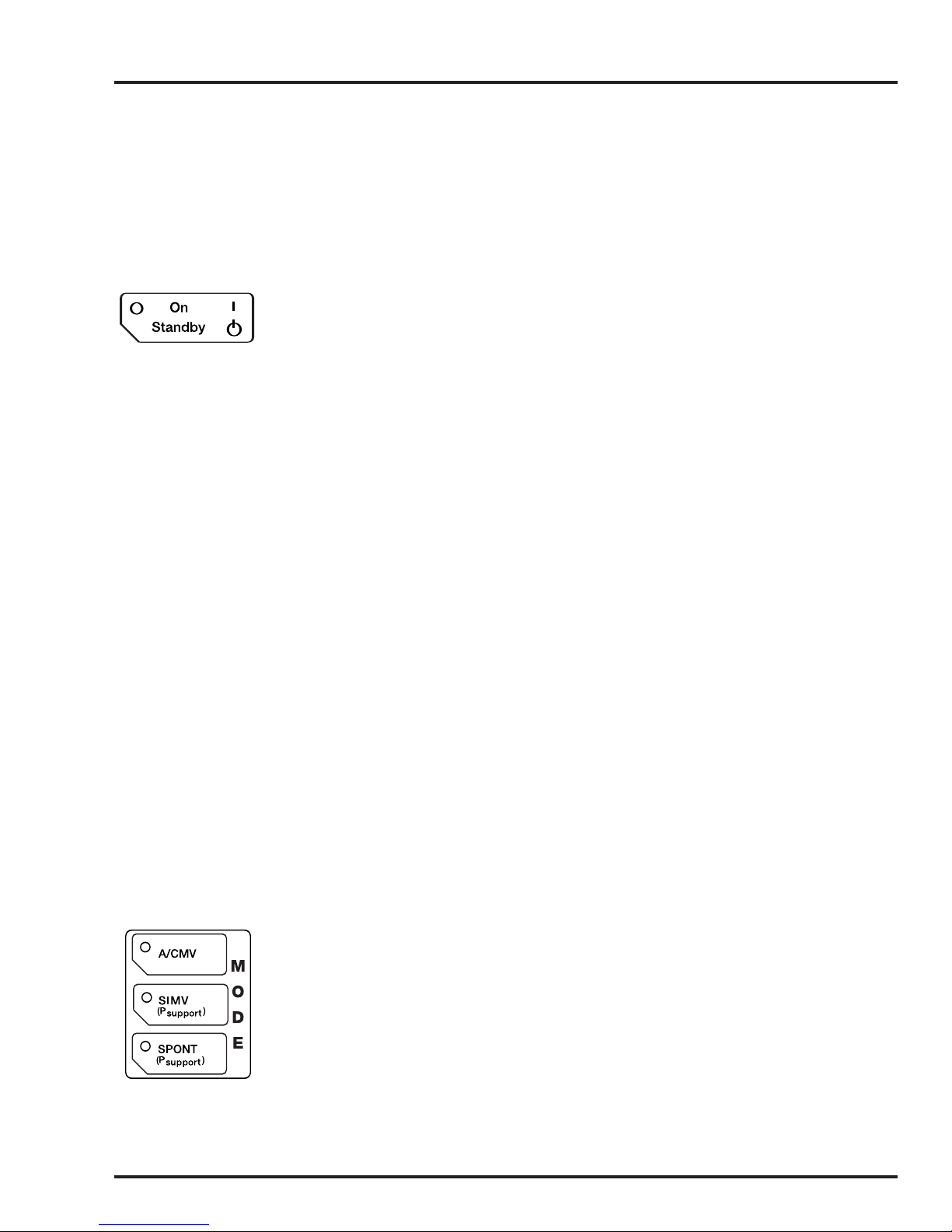
The On/Standby button toggles between the following conditions:
Changing the MODE Control
Setting Condition Press the A/CMV, SIMV or SPONT button.The LED on the
On Condition Press the A/CMV, SIMV or SPONT button.The LED on the
Standby
Press On/Standby button once to go from Standby to Setting.
Press again to tur
Standby: HT50 dormant.
Setting: Enables setting of control parameters and exhalation
valv
On: Enables ventilation
NOTE: There is approximately a two second delay in going from
Standby to Setting condition. During this time, the HT50 performs a
self test and will light all displa
The MODE control buttons ( A/CMV / SIMV / SPONT ) function
differently in Setting and On conditions.
selected Mode will light g
selected Mode will b
will read “PRESS AGAIN.” Press the button again within 5
seconds to confirm the mode change, or the previously selected
mode will continue.
g Setting g On gg
n On. Press twice to go from On to Standby.
e calibration.
ys on the front panel.
reen to confirm the selection.
link green and the Message Display Window
Standby
Changing between Pressure Control and Volume Control
On Condition: A/CMV or SIMV Select—Adjust (▲Up / ▼Down)—Accept
SERHT50NA A0808 3-1
The Pressure Control and Volume Control buttons function
differently when in A/CMV or SIMV in On condition compared to
when in SPONT mode in On condition or Settings condition.
Select the Pressure Control or Volume Control button. Both the
LED indicator and the target value will blink.
Adjust the blinking target value for the selected control with the
▲Up / ▼Down buttons.
To Accept the new control and target v
desired control button (Volume or Pressure) a second time.
alue you must press the
Page 26

DESCRIPTION OF CONTROLS, INDICATORS, ALARMS & CONNECTIONS
On Condition: SPONT
or
Setting Condition: A/CMV, SIMV, or SPONT
Select—Adjust (▲Up / ▼Down)—Accept
Select the Pressure Control or Volume Control button. Both the
LED indicator and target v
Adjust the blinking target value for the selected control with the
▲Up / ▼Down buttons.
Accept the new control and target value by either pressing the
selected b
new parameter for adjustment, or by waiting 5 seconds without
making a change.
Note: The transition to a new pressure or volume target may
require se
utton again; or by pressing another button to select a
veral breaths.
alue will blink.
Changing a Parameter (or Multiple Parameters)
Select—Adjust (▲Up / ▼Down)—Accept
Select the parameter by pressing the labeled button (i.e. ƒ, Ptrig,
The parameter’s numeric display will blink.
etc).
Adjust the numeric value with the ▲Up / ▼Down buttons.
Accept the value by either pressing the selected button again; or
by pressing another b
adjustment, or by waiting 5 seconds without making a change.
Enabling/Disabling Auto Panel Lock
Auto Panel Lock can be enabled or disabled via User Set Up (see
pg 3-27). When the Auto Panel Lock is enabled, the Panel will lock
30 seconds after the last button is pushed and the LED lights
green. All touch buttons (except Silence/Reset and Internal
Battery Test) are locked, preventing accidental parameter
changes.
utton to select a new parameter for
3-2 SERHT50NA A0808
NOTE: Auto P
To temporarily unlock parameters when Auto Panel Lock is active,
push the Push To unlock button for at least one second. The
Panel will relock 30 seconds after the last button is pushed.
anel Lock is factory preset to “Disabled” (off).
Page 27
SECTION 3
SERHT50NA A0808 3-3
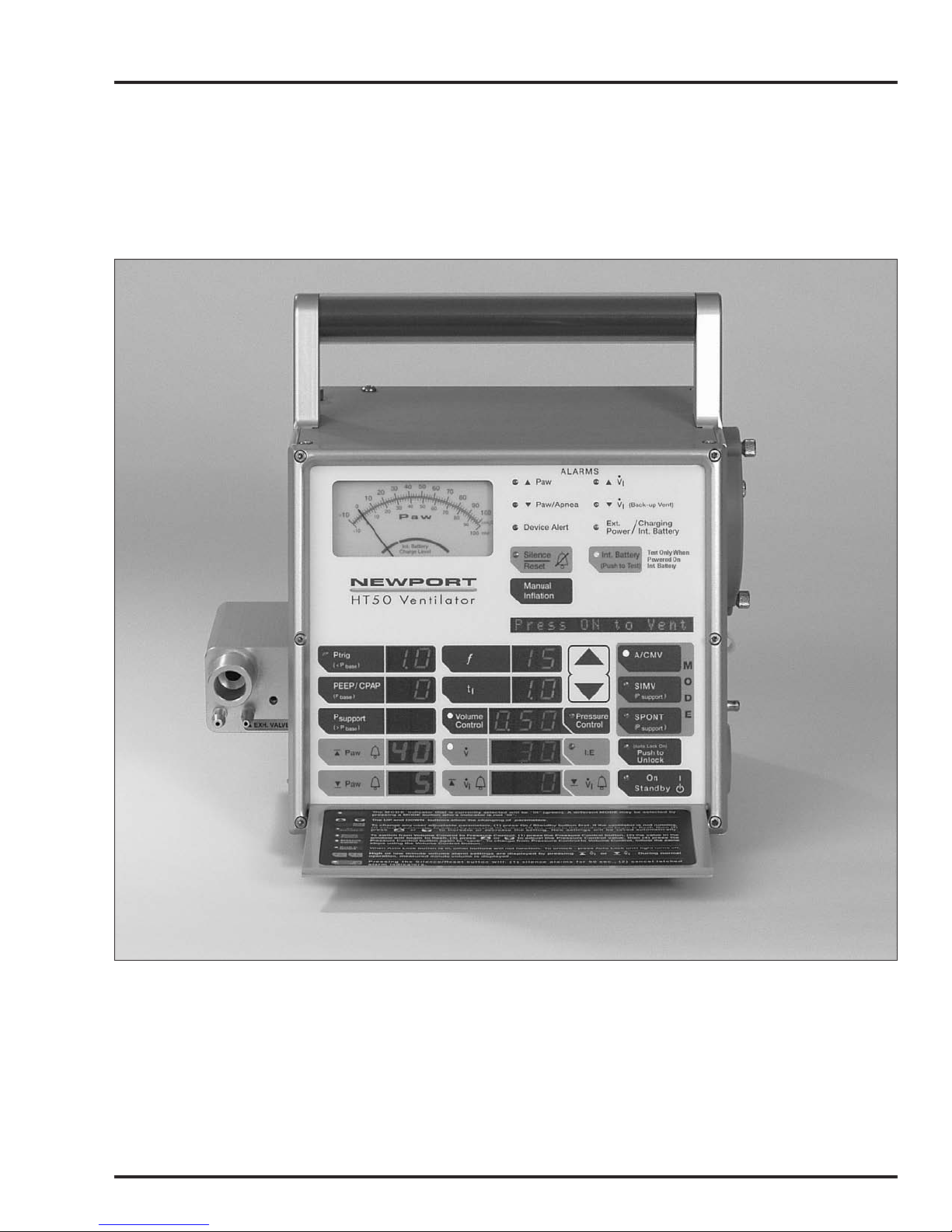
Figure 3-1
HT50 Ventilator Front Panel
(model HT50-H1, HT50-H1B)
Page 28
DESCRIPTION OF CONTROLS, INDICATORS, ALARMS & CONNECTIONS
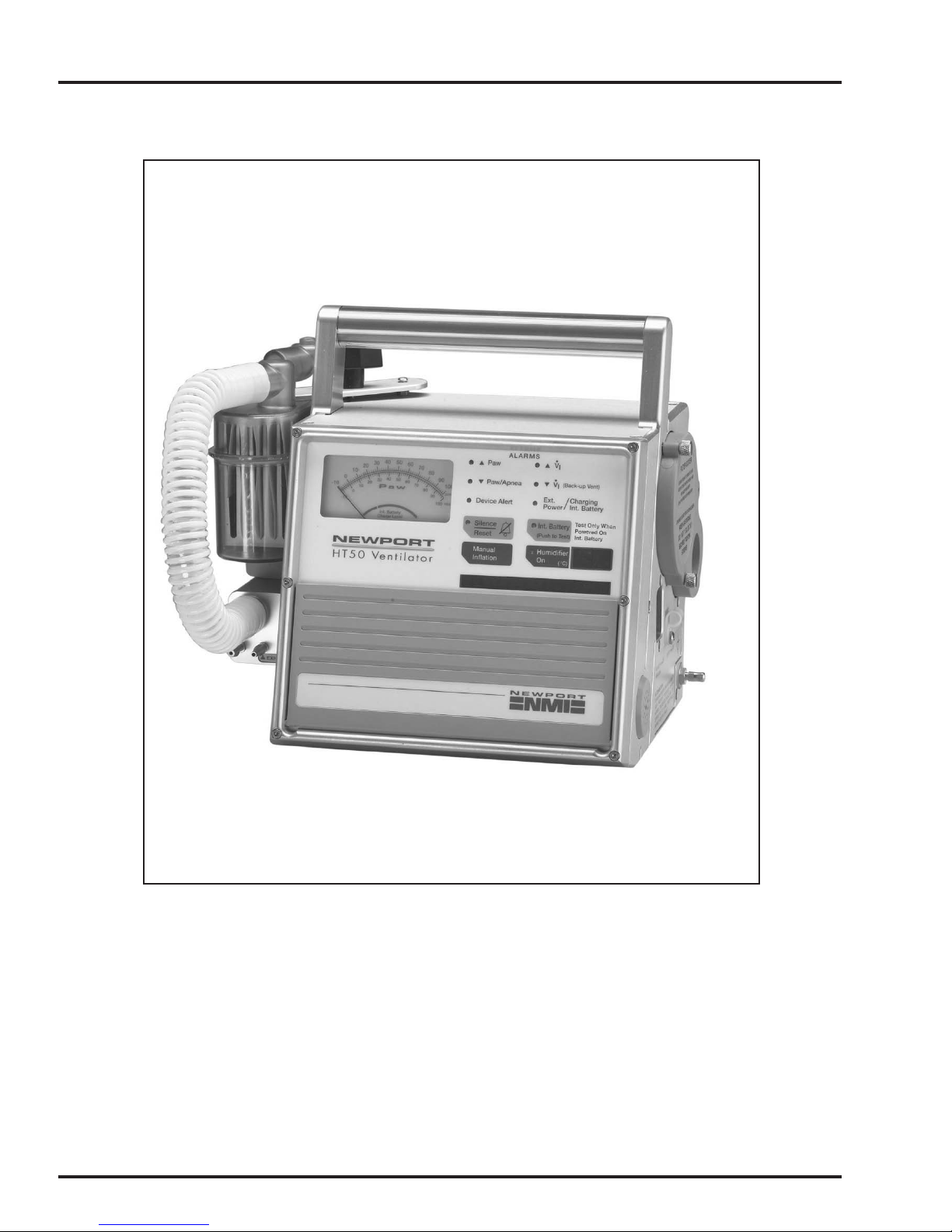
Newport HT50-H, HT50-HB (with built-in humidifier)
3-4 SERHT50NA A0808
Figure 3-2
Page 29
FRONT PANEL CONTROLS & INDICATORS
Front panel controls that have corresponding LED indicators are
included with the description of the control.
The HT50 front panel is shown in Figure 3-1 on pg 3-3.
On / Standby
This button toggles between the following conditions:
Standby (if attached to external power, the battery is being charged)
g Setting (allows setting of control parameters) g On (enables
ventilation)
Standby: The HT50 is dormant and ventilation is not enabled. If
attached to e
LED is lit green, indicating that the internal battery is being charged.
The On/Standby indicator is not lit.
Setting: Pressing the On/Standby button once changes the
entilator from Standby to Setting condition.
v
gg
Standby
xternal power, the Ext. Power/ Charging Int. Battery
SECTION 3
MODE Control
NOTE: There is approximately a two second delay in going from
Standb
self test and will light all displays on the front panel.
During Setting condition, all adjustable LEDs are lit. This allows
the operator to preset and adjust controls prior to ventilation. The
On/Standby indicator is not lit. The Message Display Window
shows “Press ON to Vent,” suggesting that the On/Standby button
needs to be pressed if you want the HT50 to start ventilation.
On: Pressing the On/Standby b
ventilator from Setting to On. In the On condition, the HT50 is
ventilating and the On/Standby indicator is lit green.
Pressing the On/Standby button twice while in On condition turns
the ventilator from On to Standby.
The MODE control buttons enable the user to switch between the
following operational modes:
• A/CMV
• SIMV
• SPONT
y to Setting condition. During this time, the HT50 performs a
utton once more changes the
SERHT50NA A0808 3-5
In A/CMV and SIMV, mandatory breaths can be pressure
controlled or volume controlled. A green LED indicates which
operational mode is active.
Page 30

DESCRIPTION OF CONTROLS, INDICATORS, ALARMS & CONNECTIONS
If the HT50 is in Setting condition, changes are made by pressing
the requested MODE button once. If in ON condition, changes are
made by pressing the requested MODE button twice. After the
first press, the Message Display Window reads “PRESS AGAIN”
and the requested MODE’s indicator starts to blink. If the
requested MODE button is not pressed within 5 seconds, the
change is cancelled.
A/CMV
(Assist / Control Mandatory Ventilation)
In A/CMV, the user may choose to pressure or volume control
mandatory breaths. In either case, all breaths delivered to the patient,
whether time (ventilator initiated) or patient-triggered, are the same.
The ƒ (frequency) setting determines the minimum number of
time-triggered mandatory breaths delivered each minute. The
Ptrig setting determines the airway pressure threshold that patient
effort must reach to trigger additional mandatory breaths. If
patient effort doesn’t cause airway pressure to drop enough to
meet the Ptrig threshold, or if the patient doesn’t breathe, the
HT50 will deliver the set ƒ (frequency) of mandatory breaths.
NOTE: If the Ptrig setting is not adjusted to a level that allows the
patient’s inspir
as CMV (control) mode.
atory effort to be detected, A/CMV mode performs
SIMV
(Synchronized Intermittent Mandatory Ventilation)
In SIMV, the user may choose to pressure or volume control
mandatory breaths. In either case, all mandatory breaths
delivered to the patient, whether time (ventilator initiated) or
patient-triggered, are the same. In addition, the user may choose
to pressure support the spontaneous breaths in between
mandatory breaths.
Unlike A/CMV, the ƒ (frequency) setting in this mode determines
the total rather than the minimum number of time (ventilator) or
patient triggered mandatory breaths delivered each minute.
The ƒ (frequency) setting also establishes a timing window which
determines whether a patient trigger results in a mandatory
breath or a spontaneous breath.
The Ptrig setting determines the airway pressure threshold that
patient effort must reach to trigger mandatory breaths and also to
trigger spontaneous breaths in between mandatory breaths.
3-6 SERHT50NA A0808
If patient effort doesn’t cause airway pressure to drop enough to
meet the Ptrig threshold or if the patient doesn’t breathe, the
HT50 will deliver the set ƒ (frequency) of mandatory breaths each
minute.
Page 31

SPONT
(Spontaneous Ventilation)
Up and ▼ Down Control
▲
SECTION 3
In this mode, all breaths are patient triggered by spontaneous
efforts. Psupport (Pressure Support Ventilation) may be used to
support spontaneous efforts. When PEEP/CPAP is set above 0,
the ventilator mode is CPAP (without P support) or Bilevel Positive
Airway Pressure (with Psupport).
The ▲Up/▼Down control buttons have multiple uses on the HT50.
1. Parameter Adjustment: Use the ▲Up/▼Down buttons to
adjust v
Control and Volume Control values), alarms, and humidifier
setting (if available). Select the desired parameter by pressing its
touch button once. The corresponding value (numerical display)
will blink. Press the ▲Up control to increase or the ▼Down to
decrease the affected parameter value
changes when the ▲Up/▼Down controls are pressed and held.
The v
selected parameter button again, or (2) the user selects a
different parameter, or (3) five seconds elapses. Pressing a
parameter button without pressing either the ▲Up or ▼Down
control b
current value.
entilation control parameter values (including Pressure
. The value continuously
alue adjustment is accepted if (1) the user presses the
utton within 5 seconds causes the parameter to retain its
NOTE: If in the On condition and switching betw
Control and Pressure Control, the value adjustment for the new
breath type selected (Volume or Pressure) will be accepted as
noted above, but the breath type (VC or PC) will only change if
the user presses the new breath type control button again.
2. Monitored Information: The ▲Up/▼Down controls are used to
access and displa
Window. Monitored information includes volume, frequency,
pressure values and operation information. See pg 3-23 for more
information on the Message Display Window.
When the HT50 is ventilating, and there are no alarm messages
displayed on the Message Display Window, press the ▲Up control
utton to access the monitoring information. Pressing the ▲Up
b
utton again allows you to scroll through the messages.
b
3. Changing Default Settings: The ▲Up/▼Down controls are
also used in User Set Up to change a set up value
Up on pg 3-27 for more details.
y monitoring messages in the Message Display
een Volume
. See User Set
SERHT50NA A0808 3-7
Page 32

DESCRIPTION OF CONTROLS, INDICATORS, ALARMS & CONNECTIONS
ƒ
(frequency)
Range: 1 to 99 b/min
ƒ (frequency) setting determines the minimum number of
The
time triggered mandatory breaths in the A/CMV mode and the
total number of mandatory breaths in the SIMV mode. The
frequency or rate value is displayed in the window adjacent to the
selector button.
The user is alerted to frequency settings which result in an
inverse I:E Ratio by an audible beep and an “Inverse I:E” message
in the Message Display Window. Attempts to continue increasing
the value after this alert are permitted up to an I:E Ratio of 3:1.
t
I
(inspiratory time)
NOTE: In SPONT mode, the
can be preset.
Range: 0.1 to 3.0 sec
The tIsetting determines the inspiratory time for mandatory breaths
(volume or pressure control). The selected time value is displayed
in the window adjacent to the selector button. The user is alerted to
tIsettings which result in an inverse I:E Ratio by an audible beep
and an “Inverse I:E” message in the Message Display Window.
Attempts to continue increasing the value after this alert are
permitted up to an I:E Ratio of 3:1. If the inspiratory time setting
causes the flow rate to reach the maximum or minimum level of the
flow specification, adjustment of tIceases, a beep sounds, and a
setting limitation message appears in the Message Display
Window.
NOTE: In SPONT mode, the tIsetting is not utiliz
can be preset.
NOTE: See pg. 3-24 for a list of setting limitation messages.
ƒ setting is not utilized but the value
ed but the value
Volume Control
(tidal volume)
3-8 SERHT50NA A0808
Range: 100 to 2,200 mL, ATPS
NOTE: When Volume Control is first initiated, or when a large
change is made to the v
to reach the volume setting.
Pressing this control button, followed by pressing the
▲Up/▼Down controls, allows the adjustment of the tidal volume
setting.
adjacent window displays the set tidal volume. See Theory of
Operation, pg 4-5 for more details.
When the green Volume Control LED illuminates, the
olume setting, it may take 5 or 6 breaths
Page 33

SECTION 3
Pressure Control
(target pressure)
If the V
olume Control setting causes the flow rate to reach the
maximum or minimum level of the flow specification, adjustment
of Volume Control ceases, a beep sounds, and a setting limitation
message appears in the Message Display Window.
NOTE: See pg. 3-24 for a list of setting limitation messages.
NOTE: In SPONT mode, the Volume Control is not utilized but
alue can be preset.
the v
Switching from Pressure Control to Volume Control:
Press the Volume Control button. The set tidal volume is displayed in
the adjacent windo
w if the HT50 is ventilating. A “PRESS AGAIN”
message appears in the Message Display Window.
Adjust the tidal volume level by pressing the ▲Up/▼Down controls
while the LED and n
umerical display are blinking. If the HT50 is
ventilating you will need to Press the Volume Control button again
within 5 seconds following adjustment.
Range: 5 to 60 cmH2O / mbar
NOTE: When Pressure Control is first initiated or the setting is
changed, the first f
ew breaths may cycle off early until slope/rise
is optimized. If early cycling off continues, re evaluate the
breathing circuit configuration and lengthen the tubing as
necessary.
Pressing this control button, followed by pressing the
▲Up/▼Down controls, allows the adjustment of the target airway
pressure setting. T
arget pressure is referenced to ambient
(atmospheric pressure). When the green Pressure Control LED
illuminates, the adjacent window displays the set airway pressure.
See Theory of Operation pg 4-4 for more details.
NOTE: In SPONT mode, the Pressure Control is not utilized b
ut
the value can be preset.
Switching fr
om Volume Control to Pressure Control:
Press the Pressure Control button. The set target airway pressure
value is displayed in the adjacent window if the HT50 is
v
entilating. A “PRESS AGAIN” message appears in the Message
Display Window.
Adjust the set target airway pressure by pressing the
▲Up/▼Down controls while the LED and numerical display are
linking. If the HT50 is ventilating you will need to press the
b
Pressure Control button again within 5 seconds following
adjustment.
SERHT50NA A0808 3-9
NOTE: The minimum target airway pressure is 5 cmH
above set baseline pressure.
O / mbar
2
Page 34

DESCRIPTION OF CONTROLS, INDICATORS, ALARMS & CONNECTIONS
Ptrig (sensitivity)
Range: 0.0 to –9.9 cmH2O/mbar
The Ptrig setting determines trigger sensitivity in terms of how far
airway pressure must drop below the set baseline pressure for a
patient’s spontaneous efforts to be detected. The Ptrig LED
indicator illuminates each time the airway pressure reaches the
set Ptrig level, and turns off once the airway pressure has
returned to baseline pressure. The blinking Ptrig LED is referred
to as the Patient Effort Indicator. The P trig value is displayed in
the adjacent window. Set Ptrig as close to 0.0 cmH
without autotriggering to maximize triggering synchrony.
PEEP/CPAP
Range: 0 to 30 cmH2O/mbar
The PEEP/CPAP setting establishes airway pressure in the
patient circuit during the exhalation phase. It is also referred to as
base or baseline pressure. The set PEEP/CPAP value is displayed
in the adjacent window.
O as possible
2
Psupport
(pressure support)
NOTE: In Pressure Control ventilation, PEEP/CPAP cannot be
set higher than 5 cmH
O/mbar below the set Pressure Control
2
setting.
NOTE: The value of PEEP/CPAP plus Psupport cannot exceed
60 cmH
O/mbar.
2
Range: 0 to 60 cmH2O/mbar
The Psupport (pressure support) setting determines the target
rise/change in pressure during inspiration for patient triggered
spontaneous breaths in SIMV and SPONT modes. The target
pressure is the set Psupport plus the PEEP level.
Any time the active Psupport control is pressed, Psupport flow
delivery slows to a lower level then it gradually increases to the
appropriate level as pressure rise is re-assessed.
NOTE: The value of PEEP/CPAP plus Psupport cannot exceed 60
O/mbar.
cmH
2
3-10 SERHT50NA A0808
Page 35

Manual Inflation
SECTION 3
Range: 0 to 3.0 sec
Pressing this button delivers an operator initiated Manual Inflation.
Pressing the Manual Inflation button will not initiate an inflation if
the patient is currently in the inspiratory phase of a breath or if
airway pressure is > 5 cmH
level. Manual Inflation delivers the set flow rate (in Volume
Control) or the set target pressure (in Pressure Control), but
inspiratory time is controlled by the user.
During Manual Inflation, the breath is terminated if (1) the Manual
Inflation button is released, or (2) the ▲Paw (High Pressure)
m is violated or (3) three seconds have elapsed.
alar
NOTE: Manual Inflation is only available in A/CMV and SIMV modes.
NOTE: Manual Inflation may be prematurely cycled off in the first
veral breaths in Pressure Control when the initial flow has not yet
se
been optimized.
O (mbar) above the set PEEP/CPAP
2
Humidifier On Button
(HT50-H, HT50-HB only)
Range: 19ºC to 39ºC
This touch button activates the b
uilt-in humidifier. Pressing this button
displays the set target temperature in the adjacent window. While the
display is blinking, use the ▲Up/▼Down controls to adjust the
target temper
ature. When temperature adjustment is complete
and (1) five seconds have elapsed without touching the control,
(2) the Humidifier On button is pressed again, or (3) another
parameter is selected for adjustment, the display stops blinking
and the measured temperature is displayed. While the humidifier is
On, the target temperature can be readjusted at any time by
pressing the Humidifier On button and using the ▲Up/▼Down
controls
.
NOTE: Preheating the humidifier for 30 minutes prior to beginning
entilation will improve the heating performance of the humidifier.
v
During ventilation (On condition) the displayed temperature is the
measured temperature at the patient connector. In the Setting
condition, the displayed temperature is the measured temperature
at the humidifier bottle outlet.
SERHT50NA A0808 3-11
To turn the humidifier Off, press and hold the Humidifier On button
for three seconds. See pg 5-11 for more details.
NOTE: The measured proximal temperature may be different
from the set target temperature due to the environmental
temper
ature, minute volume, patient temperature, etc.
Page 36

DESCRIPTION OF CONTROLS, INDICATORS, ALARMS & CONNECTIONS
NOTE: The humidifier is operational only when the HT50 is
powered by external A.C. power.
NOTE: If the humidifier and/or the temperature probe is removed or
ved prior to turning the
•
V
(mandatory flow)
malfunctions or if the humidifier bottle is remo
humidifier off, the Humidifier On LED changes from green to blinking
yellow, an audible alarm sounds and the heater shuts down
automatically. To restart the humidifier, correct the alarm condition
and press the Humidifier On button.
Range: 6 to 100 L/min
•
shares a numeric display window with I:E Ratio.
V
•
LED is illuminated green when flow is displayed.
V
Displays the calculated flow delivered from the ventilator during
volume controlled mandatory breaths. V
during Pressure Controlled breaths or SPONT mode.
NOTE: Flow can be adjusted indirectly by changing the tidal
olume (Volume Control) or tIsettings.
v
I:E Ratio
(inspiratory time to expiratory time)
e: 1:99 to 3:1
Rang
I:E Ratio shares a numer
I:E LED is illuminated green when I:E Ratio is displayed.
I:E Ratio is determined by the
is longer than inspiratory time, the display format is 1:X.X. If
expiratory time is shorter than tI, the display format is X.X:1. When
the I:E Ratio is inverse, the I:E Ratio indicator illuminates once every
breath. I:E Ratio does not function during SPONT mode.
Internal Battery Test Button and Indicator
When the HT50 is powered by the dual internal battery, the LED
on this button illuminates. A yellow LED indicates the internal
battery system is in use. A blinking yellow LED indicates low
power. When the battery system is completely discharged, the LED
blinks red.
•
display is not available
ic display window with V
ƒ and t
settings. If expiratory time
I
•
.
3-12 SERHT50NA A0808
Pressing this button allows the Int. Battery Charge Level to be
read in the lower half of the Paw meter window. The battery
charge level should only be tested when the HT50 is operating on
the dual internal battery. Testing while plugged into any external
power source will give inaccurate readings.
Test the HT50 dual internal battery periodically to verify that the
charge level is in the blue area. The numbers on the Paw meter do
not reflect the percent of charge.
Page 37

Internal Battery Charge Level Meter
The Int. Battery Charge Level meter is located beneath the Paw
meter. If the needle is in the red when the test button is presed the
battery charge is low.You should use an external power source.
The blue area indicates medium to full battery charge. Each
battery use time is different based on your conditions. The
numbers on the Paw meter do not reflect the percent of charge.
NOTE: The battery charge level is best maintained by keeping
the HT50 contin
uously plugged into an external power source.
Push to Unlock Button and Auto Lock Indicator
Auto Panel Lock can be enabled or disabled via User Set Up (see
pg 3-29). When Auto Lock is set to “Enabled” in User Set Up and
the ventilator is in On condition and 30 seconds have elapsed
without pressing any buttons, the Auto Lock function is
automatically activated and the (Auto Lock On) LED illuminates
green. When Auto Lock is active, all touch buttons (except
Silence/Reset and Int. Battery Test) are locked, preventing
accidental changes.
SECTION 3
Silence / Reset
Press and hold the Push to Unlock button for at least one second
to unlock the panel and enable the activation of all touch buttons
for adjustment. An audible beep sounds and the LED is
extinguished. When 30 seconds have elapsed without pressing
any buttons, the Auto Lock is automatically activated again.
NOTE: Auto Panel Lock is factory preset to “Disabled” (off).
The Silence/Reset button has three functions:
1. Silencing alarms: Press the Silence/Reset button to silence all
alarms for 60 seconds. When the Silence/Reset indicator is
illuminated, all alarms are silenced except Device Alert alarm.
Press the Silence/ Reset button again to cancel the silence
period.
2. Clearing alarm messages: Press the Silence/Reset button to
clear all alarm messages in the Message Display Window and
to release latched LED indicators when the cause for the
alarm is no longer present.
3. Toggle Buzzer Volume (alarm loudness) between Loud and
Quiet: Press and hold the Silence/Reset button when there
are no alarm messages displayed to toggle the alarm audible
volume between loud and quiet. The alarm will sound at the
new setting.
SERHT50NA A0808 3-13
Page 38

DESCRIPTION OF CONTROLS, INDICATORS, ALARMS & CONNECTIONS
NOTE: The Battery Empty Alarm and the Device Alert Alarm can
not be silenced permanantly. These alarms indicate that an alternate
source of ventilation must be utilized. See pgs 3-20 and 3-21 for
more details.
Paw Meter
(airway pressure meter)
Range: –10 to 100 cmH2O / 98 mbar
The Paw meter displays airway pressure. It also indicates the
internal battery charge level when the Int. Battery button is
pressed.
FRONT PANEL ALARMS
The front panel alarm LED indicators blink when an alarm limit
setting is violated. Once the violation is no longer in effect, the
indicators latch (remain steadily lit) until they are reset by
pressing the Silence/Reset button.
High ▲ Paw and Low ▼ Paw Alarm Control and Display
(airway pressure)
Range: Paw –10 to 100 cmH2O / 98 mbar
High ▲Paw Alarm 4 to 99 cmH
Low ▼
The ▲Pa
pressure alarm setting.
The ▼
pressure alarm setting.
To adjust either alarm, press the desired button once. The value in
the adjacent display window will blink. Use the ▲Up/▼Down
controls to adjust the display
setting can be retained by (1) pressing the selected button again
to accept the alarm setting, (2) selecting another parameter for
adjustment, or (3) allowing five seconds to elapse without
adjustment.
NOTE: In SPONT mode the ▼
value can be preset.
w button allows the selection of the high (peak) airway
Paw button allows the selection of the low peak airway
Paw Alarm 3 to 98 cmH2O / 96 mbar
O / 97 mbar
2
ed alarm setting value.The new
Paw alarm is inactive but the
3-14 SERHT50NA A0808
NOTE: The ▼
PEEP/CPAP + 3. The ▲Pa
least 1 above the ▼
Paw alarm setting cannot be a value below
Paw alarm setting.
w alarm setting must be a value at
Page 39

▲ Paw (High Pressure) Alarm
(user adjustable)
▼ Paw (Low Pressure) Alarm
(user adjustable)
SECTION 3
Audible Alarm: Intermittent beep
Visual Alarm: ▲Paw indicator blinks red
Message Window: HIGH PRESSURE
The High ▲Paw Alarm is activated when airway pressure (Paw)
reaches the ▲Paw alarm limit setting. Any breath in progress
immediately cycles to e
when Paw falls below the Paw alarm limit setting and at least one
second has elapsed since the alarm was activated.
Audible Alarm: Intermittent beep
Visual Alarm: ▼Paw indicator blinks red
Message Window: LOW PRESSURE
xhalation. The alarm violation is cancelled
High ▲ V
•
and Low ▼ V
I
•
Alarm Control and Display
I
(inspiratory minute volume)
The Low ▼Paw Alarm is activated when airwa
below the ▼
Paw alarm limit setting for two consecutive mandatory
y pressure remains
breaths. The alarm violation is cancelled when one mandatory
breath is delivered without a ▼Pa
w alarm violation.
NOTE: The Low ▼Paw Alarm does not function in SPONT mode.
The ▼Paw alarm limit does not apply to spontaneous breaths in
SIMV mode.
Range: V
This window displays the inspiratory minute volume (in liters) and
is automatically updated every 10 seconds. The V
displays the delivered minute volume, except when the user is in
the process of setting either the High or Low V
To adjust the High or Low V
•
I
High ▲ V
Low ▼
•
V
•
Alarm 1.1 to 50.0 L/min
I
Alarm 0.1 to 49.0 L/min
I
•
alarm limit, press the ▲or ▼ V
I
0 to 99.0 L/min
•
I
•
alarm limit.
I
window always
•
I
button. The value in the adjacent display window will blink. Use
the ▲Up/▼Down controls to adjust the displayed alarm limit
alue. The new limit can be retained by (1) pressing the selected
v
button again to accept the alarm setting, (2) selecting another
parameter for adjustment, or (3) allowing five seconds to elapse
without adjustment.
SERHT50NA A0808 3-15
NOTE: The high inspiratory minute volume alarm limit is limited
to 1 > the low alar
m limit setting. The low alarm limit is limited to 1
< the high alarm limit setting.
Page 40

DESCRIPTION OF CONTROLS, INDICATORS, ALARMS & CONNECTIONS
•
▲ V
(High Insp. Minute Volume) Alarm
I
(user adjustable)
•
▼ V
(Low Insp. Minute Volume) Alarm
I
Back-up Ventilation
(user adjustable)
Audible Alarm: Intermittent beep
Visual Alarm: ▲V
Message Window: HIGH V
The High Insp. Minute Volume Alarm is activated when the
delivered inspiratory minute volume exceeds the High ▲ V
setting. The alarm is cancelled after delivered inspiratory minute
volume falls below the ▲V
•
indicator blinks red
I
•
i
•
alarm setting.
I
•
alarm
I
WARNING The Insp. Minute Volume Alarms are based on the
ered volume from the ventilator. The actual minute volume
deliv
in the patient lungs may be significantly different in cases such
as circuit leak, disconnection, and pneumothorax. To verify the
exhaled minute volume, use a separate exhaled volume
monitor.
Audible Alarm: Intermittent beep
Visual Alarm: ▼V
Message Window: LOW V
•
indicator blinks red
I
•
i
•
LOW V
i (BUV) (if back-up ventilation is active)
The Low Insp. Minute Volume Alarm is activated when delivered
inspiratory minute volume falls below the Low ▼
•
V
alarm limit
I
setting.
WARNING The Insp. Minute Volume Alarms are based on the
ered volume from the ventilator. The actual minute volume
deliv
in the patient lungs may be significantly different in cases such
as circuit leak, disconnection, and pneumothorax. To verify the
exhaled minute volume, use a separate exhaled volume
monitor.
Back-up Ventilation
Back-up Ventilation is an alarmed function that activates when the
delivered inspiratory minute volume (V
setting. During Back-up Ventilation, the Low ▼V
alarm indicator blinks, an audible alarm sounds, and “LOW V
•
) falls below the Low ▼V
I
•
(Back-up Vent)
I
•
I
•
i (BUV)”
is displayed in the Message Display Window. The ventilation settings
employed by Back-up Ventilation are then displayed on the front
panel. Back-up Ventilation ceases when V
•
I
= ▼V
•
+ 10%, at which
I
time ventilation and front panel displays return to user-set values.
Back-up Ventilation is functional in all modes. See page 4-5 for a
complete description of Back-up Ventilation.
3-16 SERHT50NA A0808
Page 41

High Baseline Pressure Alarm
(automatic)
SECTION 3
Audible Alarm: Intermittent beep
Visual Alarm: ▲Paw indicator blinks red
Message Window: HIGH Pbase
Occlusion Alarm, Circuit
(automatic)
Occlusion Alarm, Device
(automatic)
The High Baseline Pressure (High P
when airway pressure is above the Low ▼
base) alarm is activated
Paw alarm limit setting
at the beginning of a time activated mandatory breath. The alarm
resets when Paw drops to within 5 cmH
O / mbar of the set
2
PEEP/CPAP level.
Audible Alarm: Intermittent beep
Visual Alarm: ▲Paw indicator blinks red at the high
iority rate
pr
Message Window: OCCLUSION
An Occlusion alarm is activated when airwa
the set PEEP + 15 cmH
O/mbar at 3 seconds after the beginning
2
y pressure is above
of expiration, or at the end of expiration, whichever comes first.
When a breathing circuit occlusion occurs, the ventilator will be
unable to release the pressure, therefore additional breaths will
not be delivered until the condition is corrected. The alarm resets
when airway pressure falls to within 15 cmH
O/mbar of baseline,
2
at which point breath delivery is resumed.
Audible Alarm: Intermittent beep
Visual Alarm: ▲Pa
w indicator blinks red at the high priority
rate and Device Alert indicator blinks
Message Window: OCCLUSION
SERHT50NA A0808 3-17
An Occlusion alar
the set PEEP + 15 cmH
m is activated when airway pressure is above
O/mbar at 3 seconds after the beginning
2
of expiration, or at the end of expiration, whichever comes first.
When the Occlusion alarm is caused by a malfunction inside the
ventilator, the HT50 will attempt to relieve circuit pressure through
its redundant safety system. If successful, ventilation will continue,
but in an alarmed state. It is possible that the condition causing
the alarm will self-correct, in which case the alarm is reset.
Otherwise, the ventilator will continue to alarm until the necessary
service is performed. If the HT50 is unsuccessful in relieving
circuit pressure, additional breaths will not be delivered unless
airway pressure falls to within 15 cmH
O/mbar of baseline.
2
Page 42

DESCRIPTION OF CONTROLS, INDICATORS, ALARMS & CONNECTIONS
WARNING Any time a Device Alert violation occurs along
with the message “OCCLUSION,” an alternate method of
ventilation should be provided for the patient as soon as
possible so that the cause of the violation can be adequately
and safely investigated.
Low Baseline Pressure Alarm
(automatic)
Audible Alarm: Intermittent beep
Visual Alarm: ▼Paw/Apnea indicator blinks red
Message Window: LOW Pbase
Check Prox Line Alarm
(automatic)
The Lo
unstable baseline (leak in the breathing circuit) or by a baseline
decrease since the last PEEP/CPAP control change. A Low Pbase
violation occurs in all modes when airway pressure remains >
cmH
blinks during Low ▼Paw violations blinks when this alarm is
activated. The alarm resets when airway pressure is < 3
cmH
Audible Alarm: Intermittent beep
Visual Alarm: ▼Paw/Apnea indicator blinks red
Message Window: CHECK PROX LINE
The Chec
the pressure measurement of the proximal pressure sensing line
is significantly different from the internal back up pressure sensing
line located inside the ventilator. This may be caused by a
disconnected, kinked, water-filled proximal sensing line, or a
blocked proximal line filter.Ventilation is continued during the
alarm condition, using the pressure measurement of the internal
sensing line.
w Baseline Pressure (Low Pbase) Alarm is activated by an
O/mbar below baseline for 3 seconds.The same LED that
2
O/mbar below baseline.
2
k Prox Line Alarm is activated when, during inspiration,
3
Apnea Alarm
(automatic)
3-18 SERHT50NA A0808
Audible Alarm: Intermittent beep
Visual Alarm: ▼Paw/Apnea indicator blinks red
Message Window: APNEA
The Apnea Alar
detected spontaneous efforts occur for 30 seconds. The alarm is
reset by a time or patient trigger.
NOTE: The Apnea Alarm does not activate Back-up Ventilation.
m is activated when no mandatory breaths or
Page 43

PCV Not Reached Alarm
(automatic)
SECTION 3
Audible Alarm: Intermittent beep
Visual Alarm: ▼Paw/Apnea indicator blinks red
Message Window: PCV NOT REACHED
Humidifier Alarm
(automatic) HT50-H only
The PCV Not Reached Alar
ventilation when the maximum inspiratory pressure (Paw P) is
less than 50% of the target pressure for 2 consecutive mandatory
breaths. The alarm is reset when maximum inspiratory pressure
(Paw P) is >
Audible Alarm: Intermittent 3-pulse caution beep
Visual Alarm: Humidifier indicator blinks yellow
The Humidifier Alar
conditions occur in the HT50 built-in humidifier. When an alarm
condition is detected the humidifier heater shuts down.
There are five humidifier alarms:
Messa
Check Humidifier Bottle removed or not clamped
50% of the target pressure.
m is activated when any of the following
ge Display Window Cause of Alarm
m is activated in pressure control
properly when trying to activate
the humidifier.Temp Probe not
connected or missing when
trying to activate the humidifier.
Humidifier Fail Bottle removed while humidifier
is On. Failure of the primary
humidifier control.
Check Temp Probe Temp Probe damaged or
missing while humidifier is On.
High Prox Temp Proximal temperature exceeds
set target temperature by 4°C
when set at >
set at < 34°C.
High Temp Core Excessive temperature in the
humidifier heating element.
NOTE: The Humidifier Alarm is automatically set when using the
HT50 humidifier. Humidifier Alarms (and the built-in humidifier) do
not function when the HT50 is po
wered on internal battery.
34°C or 6°C when
SERHT50NA A0808 3-19
Page 44

DESCRIPTION OF CONTROLS, INDICATORS, ALARMS & CONNECTIONS
Battery Low Alarm
(automatic)
Audible Alarm: Intermittent 3-pulse caution beeps
Visual Alarm: Int. Battery indicator blinks yellow
Message Window: Battery Low
Battery Empty Alarm
(automatic)
Indicates that a minim
remains in the dual internal battery. Pressing the Silence/Reset
button will cancel the audible three-pluse caution beeps but the
visual alarm will continue to blink and the alarm will beep once
every three minutes as long as the alarm condition continues. The
alarm is reset when A.C. or external D.C. power is connected to
the HT50.
NOTE: The battery condition and ventilator settings will affect
remaining time
Audible Alarm: Intermittent beep
Visual Alarm: Int. Battery indicator blinks red
Message Window: BATTERY EMPTY
Indicates that a minimum of 15 minutes of oper
remains in the dual internal battery. An alternate power source
must be located immediately. This alarm can only be temporarily
silenced as long as the alarm condition continues. The alarm is
reset when A.C. or external D.C. power is connected to the HT50.
, but it will be at least 30 minutes.
um of 30 minutes of operating power
ating power
NOTE: The battery condition and v
remaining time, but it will be at least 15 minutes.
NOTE: Frequent deep discharge of the dual internal battery will
decrease the amount of time the HT50 will oper
power from a full charge state. Replace the battery when battery
operation time is insufficient for application.
WARNING Immediately secure an external power source when
the Battery Empty alarm is violated. Charge the batter
minimum of 5 hours (~80% recharged) before powering the
ventilator again from the internal battery. If the battery is completely
depleted, it takes approximately 7 to 8 hours to fully recharge.
NOTE: If the HT50 is to be pow
for an extended period, ensure that the dual internal battery is fully
charged prior to use.
entilator settings will affect
ate on battery
y for a
ered from the dual internal battery
3-20 SERHT50NA A0808
Page 45

Fault, Battery System Alarm, Device Alert
(automatic)
Audible Alarm: Intermittent beep
Visual Alarm: Device Alert indicator blinks red
Message Window: FAULT BAT SYS
SECTION 3
Power Switchover Alarm
(automatic)
The status of the inter
continuously monitored and any deficiency will result in a Battery
Fault Alarm. The HT50 will continue to operate properly from an
external power source but it can not be powered by the internal
battery system.
NOTE: If the “Fault Bat Sys” device alert alarm occurs, keep the
HT50 plugged into an e
Medical Technical Service Dept.
Audible Alarm: Intermittent 3-pulse caution beeps
Visual Alarm: Ext. Power indicator illuminates red
Messag
The Power Switchover Alarm is activated by switching from
external power to the dual internal battery due to disconnection
from the power cord or a power interruption. Pressing the
Silence/Reset button will (1) cancel the audible alarm, (2) cancel
the “No ext power” message, (3) cancel the Ext. Power LED and
(4) cause the Int. Battery LED to change to non-blinking yellow
indicator.
e Window: No ext power
nal battery system and the charging system is
xternal popwer source. Contact Newport
Battery indicator blinks yellow
Int.
Device Alert Alarm
(automatic)
SERHT50NA A0808 3-21
If external power is connected within 60 seconds following internal
battery operation, the HT50 will immediately switch back to
external power. If internal battery operation has lasted longer than
60 seconds, there will be a delay of up to an additional 60
seconds before the HT50 will switch back to external power. If “No
ext power” message is still displayed following the re-connection
to external power, press Silence/Reset button to cancel the
message.
Audible Alarm: Intermittent beep
Visual Alarm: Device Aler
Message Window: OCCLUSION or 10V SHUTDOWN or
T BAT SYS or SYSTEM ERROR or
FAUL
MOTOR FAULT
t indicator blinks red
Page 46

DESCRIPTION OF CONTROLS, INDICATORS, ALARMS & CONNECTIONS
The Device Alert Alarm is activated when the microprocessor
detects a functional problem with the ventilator. With the exception
of OCCLUSION & FAULT BAT SYS, all other Device Alert alarms
are non-recoverable and will result in the HT50 discontinuing
ventilation. When this occurs, the ventilator must be powered
down by pressing the On/Standby button. DO NOT use the
ventilator until the cause of the alert has been determined and
corrected.
NOTE: See Pg. 3-17, Occlusion Alarm, Device, and Pg. 3-21,
ault Battery System Alarm, for a detailed description of these
F
recoverable Device Alert Alarms.
There are three possible messages that will be displayed when a
non-recoverable Device Alert Alarm occurs; (1) MOTOR FAULT
(2) 10V SHUTDOWN and (3) SYSTEM ERROR. For MOTOR
FAULT and10V SHUTDOWN the full text message will be
displayed for 5 seconds, followed by an abbreviated form of the
message, eg. MTR Fail, or 10V Fail. A timing message will also
appear, documenting how long the condition has been present.
The format for the time is “H:MM:SS.” The SYSTEM ERROR
message will always be displayed with full text.
Shut Down Alert Alarm
(automatic)
NOTE: If the cause of the SYSTEM ERROR does not allow the
HT50 to displa
to light, the ventilator will shut down and the Shut Down Alert Alarm
will activate. Upon the next power up of the unit, the SYSTEM
ERROR message will be displayed. If the cause of the alarm has
been corrected, the message can be cancelled by pressing the
Silence/Reset button.
WARNING If a non-recoverable Device Alert alarm occurs,
immediately disconnect the patient from the ventilator and
provide an alternate method of v
NOTE: A non-recov
without first turning the ventilator Off (Standby).
Audible Alarm: Intermittent beeps
Visual Alarm: –
Message Window: –
The Shut Do
Off. An intermittent audible alert indicates the ventilator is no longer
operating. The intermittent beeps will continue for at least 10
minutes or until it is silenced by pressing the Silence/Reset button.
y the alarm message and the Device Alert indicator
entilation.
erable Device Alert Alarm cannot be silenced
wn Alert Alarm occurs when the ventilator is powered
3-22 SERHT50NA A0808
Page 47

FRONT PANEL MESSAGE DISPLAY WINDOW
Message Display Window
All messages and alarms are displayed in a 16 character, alpha
numeric window located above the MODE controls.
Monitoring Messages:
When the Message Display Window is blank (no message
yed) press the ▲Up control button to scroll through the
displa
monitor
volume, frequency, pressure values and operation information.
Tidal volume, peak pressure, and baseline pressure are updated
breath by breath. Frequency and mean pressure are also updated
breath by breath, using a 6 sec. rolling average for frequency and
a 60 sec. rolling average for mean pressure. Minute volume is
updated every 10 seconds using a 60 sec. rolling average.
NOTE: Monitoring Messages cannot be accessed during alarm
violations.
ing messages available. Monitored information includes
SECTION 3
There are 3 selections a
•
• VT / V
i / f
vailable:
• Paw / P / M / B
• H/S/L (or Q)
Press the ▲ Up button to scroll through the lines.Three seconds after
selecting a line
, the relevant operating parameters are displayed.
Following are the parameters for each line:
•
Line 1: “VT xxx V
VT – Tidal volume (in mL)
•
i – Insp. Minute Volume (in L/min) rounded to nearest
V
i xx f xx”
whole number
ƒ – Total number of patient or time activated breaths
detected for the last 60 seconds (in b/min)
Line 2: “Paw Pxx Mxx Bxx”
P – Peak airway pressure of last breath
M – Mean airway pressure
B – Baseline airway pressure at the end of expiration
SERHT50NA A0808 3-23
Line 3: “H xxxxx Sxxxxx L (or Q)”
H – Hour meter reading
S – Software Version
L/Q– Audible Level of Alarm (Loud or Quiet)
After 4 seconds this line will go blank. Access this information any
time by pressing the ▲ Up button.
Page 48

DESCRIPTION OF CONTROLS, INDICATORS, ALARMS & CONNECTIONS
Alarm and Caution Messages:
All alarms have corresponding messages in the Message Display
Windo
violated, they are displayed in order of medical priority. Alarm
messages override the display of monitored parameters.
Setting Limitation Messages:
The following “Setting Limitation” messages are displayed to notify
the user that adjustments ha
software defined limitations.
Reached Max V
Reached Min V
Inverse I:E: inverse I:E ratio has been reached
Reached Max I:E: inverse I:E ratio has reached 3:1
V
Peep + PS Too High: set PEEP + Psupport is higher than 60
PC – Peep Too Low: Pressure Control value minus PEEP is less
q – PEEP Too Low: High Pressure alarm limit minus PEEP is
w. See pg 2-3 for list of alarms. If more than one alarm is
ve caused parameters to reach
•
: maximum V• (flow) setting has been reached
•
: minimum V• (flow) setting has been reached
•
Unavailable: V• display is not available in Pressure Control
than 5 cmH
less than 5 cmH
O/mbar
2
O/mbar
2
LEFT SIDE CONNECTORS
Airway Pressure Connector
The following messages are provided as “prompts” or reminders.
Panel Locked: notifies user that the front panel buttons are
now locked
PRESS AGAIN: notifies user that a second press on the
same button is required in order to confirm
change requested
WARNING The round heater for the optional humidifier is
located near the left side connectors. This heater becomes
extremely hot when the humidifier is on. DO NOT TOUCH!
Measures airway pressure. Connect the proximal pressure
sensing line of the patient breathing circuit to this fitting.
WARNING Always use an inline filter (p/n HT6004701 or
alent) at the Airway Pressure Connector to protect the
equiv
internal pressure transducers from moisture or other
contaminants.
Gas Output Connector
3-24 SERHT50NA A0808
Supplies gas flow to the patient. Connect the patient breathing
circuit to this outlet.
Page 49

Exhalation Valve Connector
Temperature Probe Connector
(HT50-H model)
RS-232C Connector
SECTION 3
Controls the exhalation valve. Connect the exhalation valve
control drive line to this outlet.
Electrical connector for dual-channel temperature probes which
are used to measure the temperature in the humidifier water
bottle and the patient breathing circuit.
An 8 pin SEMCONN connector operating at 19,200 baud which
allows the ventilator system to interface with central alarm
systems and remote alarms.
NOTE: Contact your N
information regarding compatibility with specific remote monitoring
systems.
Emergency Air Intake
Allows the patient to pull ambient air into the breathing circuit in
the event of a complete system failure. Air intake opening
pressure is approximately –3 cmH
RIGHT SIDE CONNECTORS
Fresh Gas Intake And Filter Cover
EWPORT representative for more
O (–3 mbar).
2
WARNING Do not obstruct the Emergency Air Intake! Any
impediment could result in patient suff
WARNING HOME CAREGIVERS: Should a complete failure
of the ventilator occur
patient to breath from room air through the intake valve.
Blockage of the valve could result in suffocation. Check
periodically to ensure that the valve functions correctly.
, the Emergency Air Intake allows the
ocation.
SERHT50NA A0808 3-25
Environmental air enters through this 30 mm ID Fresh Gas Intake.
The air inlet particle filter is placed behind the Filter Cover to
protect the patient as well as the ventilator’s piston system from
dirt and particles. The Fresh Gas Intake is the attachment socket
for the optional HT50 Air/Oxygen Entrainment Mixer or an Oxygen
Blending Bag.
WARNING Do not block the Fresh Gas Intake.
Page 50

DESCRIPTION OF CONTROLS, INDICATORS, ALARMS & CONNECTIONS
External Power Connector
100-240 VAC, max. 2A 12-30 VDC, max. 12A
50/60/400 Hz
The HT50 uses a single inlet for both A.C. and D.C. power sources.
D.C. connections
A.C. connections
Equipotential Connector
The inlet power connector automatically recognizes A.C. voltage
ranges from 100 to 240 and D.C. ranges from 12 to 30. A Newport
approved external battery can be attached to this connector.
WARNING To ensure proper grounding and prevent possible
k hazards, this device should only be connected to
shoc
“Hospital Grade” power receptacles.
WARNING HOME CAREGIVERS: External power in the
home en
vironment must support min. 100 to max. 240 VAC
and must have a grounded receptacle.
Used for electric potential equalization.
Power Cord Ferrite
OPTIONAL ACCESSORIES
Air/Oxygen Entrainment Mixer
Use of the Power Cord Ferrite ensures that the HT50 meets EMC
requirements. Anytime the HT50 is operating on A.C. power, the
ferrite should be attached to the power cord. Operating from D.C.
power does not require the use of the ferrite.
NOTE: Alwa
ys use the A.C. power cord supplied with the HT50.
The Air/Oxygen Entrainment Mixer (p/n HT460700) is used to
blend atmospheric air with medical grade oxygen at a precise
ratio. A control knob allows for incremental adjustment from 0.21
to 1.00 F
. The high pressure oxygen hose has a standard
IO2
female DISS 1240 connection. The Mixer attaches into the Fresh
Gas Intake of the HT50 on the Filter Cover, located on the right
side of the ventilator.
3-26 SERHT50NA A0808
Pneumatic Requirements
Oxygen 35-90 psig (2.4 to 6.2 Bar)
Page 51

Oxygen Blending Bag Kit
Auto Lighter Cable
SECTION 3
The Oxygen Blending Bag Kit (p/n HT600044) is used to blend
atmospheric air with a low flow (0 to 10 L/min) medical grade
oxygen source. The Oxygen Blending Bag Kit attaches into the
Fresh Gas Intake on the Filter Cover, located on the right side of
the ventilator. This system allows the user to ventilate patients
with oxygen enriched gas from 0.21 up to 1.00 F
Pneumatic Requirements
Oxygen 0-10 L/min
The Auto Lighter Cable (p/n HT460085) allows the HT50 to be
powered through the D.C. lighter plug in an automobile. The
internal battery charges whenever the HT50 is connected to an
external power source, equal to or greater than 12 VDC, including
the D.C. lighter plug.
IO2
.
USER SET UP
The User Set Up allows the operator to select a variety of
functional parameters. User Set Up parameters must be
established before the HT50 is used for ventilation.
NOTE: HOME CAREGIVERS: The User Set Up parameters
should be defined in conjunction with y
Dealer. Once established, these parameters are kept in memory
and will be in affect each time the ventilator is powered on until the
operator enters User Set Up and makes changes.
NOTE: To enter User Set Up the HT50 must be in the Standby
condition.
o access User Set Up, when connected to A.C. power, press and
T
hold the Silence/Reset button down. When operating on internal
battery, you must press the On/Standby button while pressing and
holding the Silence/Reset button. When the Message Display
Window briefly displays the message “USER SETUP”, release the
button. The Message Display Window will next display the first
parameter. See Table 3-1.
The user may scroll through the rest of the set up parameters by
pressing the Int. Battery button. Use the ▲Up/▼Down control
b
uttons to change the parameter setting. To exit User Set Up, press
the Silence/Reset button once. The HT50 is now ready for use.
our physician or Homecare
SERHT50NA A0808 3-27
Page 52

DESCRIPTION OF CONTROLS, INDICATORS, ALARMS & CONNECTIONS
Parameter Display ▲ Up/ ▼ Down
(allows selection)
Headline USER SETUP None
Power Save Power Save ON* Toggles On/Off
Pressure Units Pressure cmH2O* Toggles cmH2O/mbar
* Factory default setting. May be
different if another setting was
selected during the previous
User Set Up.
Set up Set up USER* Toggles User/Default
Auto Panel Lock Lock DISABLED* Toggles
Enabled/Disabled
Technical Set Up Tech. Setup Refer to Service
Manual Section 5
Table 3-1: User Set Up Parameters
NOTE: Only the ▲Up/▼Down, Silence/Reset, and Int. Battery
uttons are active during User Set Up.
b
User Set Up Parameter
Power Save
Use the ▲Up/▼Down controls to toggle the Power Save function On
. To conserve battery power consumption during internal
or Off
battery operation, the Power Save function automatically blanks the
HT50’s numeric displays if the ventilator has operated for 2 minutes
with no buttons pressed or alarms violated. MODE, On/Standby, Int.
Battery indicators and message display window remain active at all
times.
If an alarm condition occurs, or any button is pressed, the Power
Save function is suspended for 2 minutes. The Power Save
feature can extend battery operating time by as much as 30%.
Pressure Units
Selects between cmH
O and mbar as the unit used on the
2
pressure meter and the various front panel controls. The HT50 is
factory set to cmH
O. Use the ▲Up/▼Down controls to toggle
2
to the mbar setting.
NOTE: For consistency, particularly in medical record keeping, it
is recommended that each institution standardiz
“cmH
O” or “mbar” operation.
2
e to either
3-28 SERHT50NA A0808
NOTE: HOME CAREGIVERS: The unit of measure, along with
other par
ameter settings, should be established by the patient’s
physician or Homecare Dealer.
Page 53

SECTION 3
Set Up
The Set Up parameter allows the operator to set the ventilator’s
star
t up settings. There are two selections, DEFAULT or USER.
Use the ▲Up/▼Down button to toggle between selections.
When USER is selected, all of the v
entilation parameters in effect
at shutdown will be saved.The saved parameters will appear next
time the ventilator is powered on.
When DEFAULT is selected, factory set default parameters will
appear next time the ventilator is powered on. Default parameters
are listed on pg 2-7.
NOTE: HOME CAREGIVERS: This parameter should always be set
to USER f
or home use to ensure that when the HT50 is powered off
and on the physician directed ventilation settings remain in place.
Auto Panel Lock
This setting allows the user to enable (turn on) or disable (tur
n
off) the Auto Panel Lock feature. For a complete description of
Auto Panel Lock see pg 3-13. The Auto Panel Lock feature is
factory set at Disabled or off. Use the sUp/tDown buttons to toggle
between Enabled and Disabled.
NOTE: HOME CAREGIVERS: Newport recommends that the Auto
Panel Lock feature be enabled in homecare environments as an
added safety f
eature to prevent accidental changes to panel controls.
Exiting User Set Up
SERHT50NA A0808 3-29
Exit by pressing the Silence/Reset button at any time.
Page 54

4. THEORY OF OPERATION
General System Overview . . . . . . . . . . . . . . . . . . . 4-1
A/CMV Mode (Assist/Control
Mandatory Ventilation). . . . . . . . . . . . . . . . . . . . 4-2
SIMV Mode (Synchronized Intermittent
Mandatory Ventilation). . . . . . . . . . . . . . . . . . . . 4-3
SPONT Mode (Spontaneous Ventilation) . . . . . . . 4-3
Psupport (Pressure Support) . . . . . . . . . . . . . . . . 4-4
Pressure Control (Pressure Control Ventilation) . . 4-4
Volume Control (Volume Control Ventilation). . . . . 4-5
Back-Up Ventilation . . . . . . . . . . . . . . . . . . . . . . . . 4-5
SERHT50NA A0808
Page 55

GENERAL SYSTEM OVERVIEW
The Newport HT50 Ventilator is a compact, lightweight, powerconservative, ventilator that is designed to provide ventilation for
adult and pediatric (infants, children & adolescents) patients with
body weight >
The HT50 Ventilator’s unique, patented dual-micro-piston gas
compressing technology allows the HT50 to operate without an
external compressed gas source, making it convenient to use in a
variety of environments such as hospitals, emergency response,
subacute facilities, homes and transport operations.
The dual micro pistons’ ability to deliver a variable flow enables
the HT50 to provide a full range of operating modes and breath
types, including Assist Control, SIMV and SPONT modes with
Volume Control and Pressure Control mandatory breaths,
Pressure Support of spontaneous breathing and servo-controlled
leak-compensated PEEP. Leak compensation helps to improve
triggering and avoid auto-triggering when a leak is present. The
HT50 may be used with an endotracheal tube, tracheal tube,
mask or mouthpiece.
SECTION 4
10 kg.
The HT50 provides monitoring of inspiratory tidal volume (every
breath), inspiratory minute volume, total respiratory rate, peak
pressure, mean pressure and baseline (PEEP) pressure. Realtime patient circuit pressure is displayed at all times on the airway
pressure gauge on the face panel.
The user sets variable alarm settings for High Pressure, Low
Pressure, High Inspiratory Minute Volume and Low Inspiratory
Minute Volume, with Back Up Ventilation provided in all modes in
response to a Low Minute Volume Alarm. There are also built in
alarms for High Baseline, Low Baseline, (Circuit) Occlusion,
Apnea, PCV Not Reached, Check Prox Line, Power Switchover
(from external to internal), Low Battery and Empty Battery and
Device Alerts. The HT50-H model also provides humidifier related
alarms.
Gas delivery to the patient may be enriched with oxygen (0.21-
1.00) using either the Air Oxygen Entrainment (50 psi) Mixer
(HT460700) or the Low Flow Oxygen Blending Bag Kit
(HT600044).
There is an Auto-Lock feature that may be enabled or disabled.
The alarm loudness may be set to two different levels.
SERHT50NA A0808 4-1
The HT50 may be operated from a variety of AC (100-240 VAC @
50 / 60 / 400 Hz) or DC (12-30 VDC) external power sources or
from the Dual Pac Internal Battery System. The Autolighter Cable
(HT460085) accessory enables connection to an automobile-type
DC outlet.
Page 56

THEORY OF OPERATION
Any time external power is connected to the ventilator, the Dual
Pac Internal Battery system is charging. And when external power
is lost, the (new and fully charged) Dual Pac Internal Battery
system takes over and powers the HT50 for up to 10 hours, at
standard ventilator settings. A Battery Low Alarm alerts the user
when a minimum of 30 minutes operating time remains.
The HT50 is available with a built-in humidifier or without.
The HT50 is very easy to set up and use with clear indications of
all ventilation and alarm settings and alarm violations.
NOTE: When the HT50 is used in a home care environment it is
important that the pr
demonstrated competency in all equipment functions. A specific
written care plan must be established by the attending physician.
NOTE: Transport of patients with the HT50 requires that medical
staff ha
problem resolution. Proper emergency back-up equipment must
be immediately available during transport.
ve a good working knowledge of the ventilator’s use and
imary caregiver has received training and has
A/CMV MODE
(Assist/Control Mandatory Ventilation)
In A/CMV mode, time activated (mandatory) breaths are delivered
in accordance with the
breaths in addition to, or in place of, time activated (mandatory)
breaths if the effort they generate causes airway pressure to meet
the Ptrig setting. Every such patient effort results in a mandatory
breath. The breath can be volume or pressure controlled.
PEEP/CPAP may be added. Tidal volume is determined by the
target pressure, tI, and patient respiratory mechanics in Pressure
Control and by the tidal volume setting in Volume Control.
As with all HT50 operating modes, Back-up Ventilation is activated
if the Low ▼V
ƒ setting. Patients can trigger mandatory
•
alarm limit is violated.
I
4-2 SERHT50NA A0808
Page 57

Figure 4-1
TIME TRIGGERED
MANDATORY BREATH
PATIENT TRIGGERED
MANDATORY BREATH
SPONTANEOUS BREATH
PRESSURE
100%
A
B
C
C
A
A
MANDATORY BREATH
INTERVAL
MANDATORY BREATH
INTERVAL
MANDATORY
BREATH
LOCKOUT
INTERVAL
A: Time Triggered Mandatory Breath
B: Patient Triggered Mandatory Breath
C: Spontaneous Breath
---: "Scheduled" Mandatory Breath not delivered because of the patient triggered mandatory
breath in the last interval
Synchronized Intermittent Mandatory Ventilation (SIMV)
SECTION 4
SIMV MODE
(Synchronized Intermittent Mandatory Ventilation)
In SIMV mode, patients receive a fixed number of volume or
pressure controlled mandatory breaths (time or patient activated)
and may breathe spontaneously between mandatory breaths, with
or without pressure support (Psupport). See Figure 4-1 for
schematic illustration. PEEP/CPAP may be added.
The first patient triggered breath in any mandatory breath interval
will be a patient triggered mandatory breath. The patient has the
rest of the interval to breathe spontaneously. If the patient does
not trigger the ventilator, and one complete mandatory breath
interval has elapsed, a time triggered mandatory breath is
delivered.
A mandatory breath lockout interval is activated whenever the
patient triggers a mandatory breath. This limits the number of
mandatory breaths (time triggered or patient triggered) the patient
receives in 60 seconds to the
As with all HT50 operating modes, Back-up Ventilation is activated
if the Low ▼V
•
alarm limit is violated.
I
ƒ (b/min) setting.
SPONT MODE
(Spontaneous Ventilation)
SERHT50NA A0808 4-3
In SPONT mode, mandatory breaths are not delivered but the
user can adjust both PEEP/CPAP and pressure support
(Psupport) levels. The patient has control over each breath.
Page 58

THEORY OF OPERATION
When PEEP/CPAP is set above 0, the ventilator mode is CPAP
(without Psupport) or Bi-level Positive Airway Pressure (with
Psupport). Ensure that Ptrig is set so the HT50 detects all
spontaneous patient efforts.
ƒ, t
Entries for tidal volume, pressure control,
limit are all inactive in SPONT mode. However, users can preset
these parameters for future A/CMV or SIMV operation.
and Low Paw alarm
I
As with all HT50 operating modes, Back-up Ventilation is activated
if the Low ▼V
PSUPPORT
(Pressure Support)
Psupport only functions during patient triggered spontaneous
breaths in SIMV and SPONT modes. During each spontaneous
breath, the ventilator supports the patient by elevating the airway
pressure to the Psupport + PEEP level. Breaths are terminated
when (1) flow to the patient drops to 25% of that breath’s peak flow
rate, or (2) the target airway pressure is exceeded by 3 cmH
(mbar), or (3) after 3 seconds of inspiration.
PRESSURE CONTROL
(Pressure Control Ventilation)
The HT50 targets and maintains patient airway pressure at the
set pressure control level throughout inspiration. Breath
termination occurs when (1) the set tIelapses, or (2) Paw
exceeds the Pressure Control setting by 8 cmH
•
alarm limit is violated.
I
O (mbar).
2
O
2
4-4 SERHT50NA A0808
NOTE: The target airwa
mandatory breaths in A/CMV and SIMV is the display setting
above ambient pressure, not above PEEP.
Both time and patient triggered mandatory breaths can be
delivered in A/CMV and SIMV Pressure Control operation. During
SIMV Pressure Control operation, patients can breathe
spontaneously between mandatory breaths with or without
pressure support.
NOTE: When disconnecting the patient circuit during PCV/PSV
ventilation, i.e
compensate for the low pressure. After reconnecting the patient
circuit, the flow will automatically readjust to meet the patient’s
demand.
. for suctioning, the flow may increase in order to
y pressure for pressure controlled
Page 59

VOLUME CONTROL
(Volume Control Ventilation)
BACK-UP VENTILATION
SECTION 4
During Volume Control ventilation, tidal volume can be set for
mandatory breaths. If a volume setting is changed while the
ventilator is operating, the change takes place in increments over
a series of breaths.
When tidal volume is adjusted, inspiratory time remains constant
•
(mandatory flow) changes.
and V
If an attempted tidal volume setting results in a flow rate in excess
of 100 L/min or less than 6 L/min, adjustment ceases and the
user is alerted by an audible beep and the message “Reached
•
Max V
Window.
NOTE: Make sure that the mandatory flow (V
to meet patient flow demands. The flow setting is displayed by
pressing the front panel button labeled V
changed by adjusting tI.
” or “Reached Min V•” will appear in the Message Display
•
) setting is adequate
•
. Mandatory flow is
Back-up Ventilation is an alarmed function that activates when the
delivered inspiratory minute volume (V
alarm limit setting. During Back-up Ventilation, the Low ▼V
up Vent) alarm indicator blinks, an audible alarm sounds, and
•
“Low V
i (BUV)” is displayed in the Message Display Window. The
•
) falls below the Low ▼ V
I
•
I
•
I
(Back-
ventilation settings employed by Back-up Ventilation are displayed
on the front panel.
Back-up Ventilation is functional in all modes.
NOTE: Back-up Ventilation is not active for 60 seconds after the
user adjusts any ventilator controls, changes modes or turns the
entilator On from the Setting condition.
v
NOTE: During Back-up Ventilation, the Silence/Reset button can
be pressed to silence the audib
le alarm. This will not cancel Back-
up Ventilation.
NOTE: Back-up Ventilation in the HT50 is based on the delivered
atory minute volume. The inspiratory minute volume may be
inspir
different from the expiratory minute volume in some conditions,
such as in the case of a patient breathing circuit or patient airway
leak.
SERHT50NA A0808 4-5
Page 60

THEORY OF OPERATION
Back-up Ventilation in A/CMV and SIMV Modes:
(Back-up Ventilation parameters are indicated on the front panel displays.)
In A/CMV or SIMV modes, mandatory breath frequency increases
by 1.5 times the frequency (
ƒ) setting, up to a maximum of 99
b/min. The minimum breath frequency delivered is 15 b/min.
The frequency (
ƒ) will only increase up to a rate that produces a 1:1
I:E ratio even if the calculated Back-up Ventilation rate is higher.
Back-up Ventilation in SPONT Mode:
(Back-up Ventilation parameters are indicated on the front panel displays.)
In SPONT mode, the MODE changes from SPONT to SIMV,
Pressure Controlled ventilation, mandatory breath frequency (
15 b/min., peak inspiratory pressure = 15 cmH
O/mbar above set
2
ƒ)=
PEEP and inspiratory time (tI) = 1.0 sec.
Cancellation of Back-up Ventilation
User Cancelled
If during Back-up Ventilation, the user adjusts any ventilation
ameter, Back-up Ventilation is suspended for one minute and
par
all user selected ventilation parameters are employed. Another 60
seconds must pass after parameter adjustments before a ▼
•
V
I
alarm violation will result in Back-up Ventilation.
Patient Cancelled
•
V
If delivered inspiratory minute volume exceeds the Low ▼
setting by 10%, Back-up Ventilation is cancelled, the audible
alarm stops, the Low ▼V
•
(Back-up Vent) alarm indicator latches
I
alarm
I
and the HT50 resumes ventilation at the user-selected
parameters.
Press the Silence/Reset button to cancel the latched alarm
indicator and alarm message in the Message Display Window.
4-6 SERHT50NA A0808
Page 61

5. CALIBRATION AND OPERATIONAL
VERIFICATION PROCEDURE (OVP)
Introduction. . . . . . . . . . . . . . . . . . . . . . . . . . . . . . . 5-1
Test Equipment Required. . . . . . . . . . . . . . . . . . . . 5-1
Pre-Test Inspection. . . . . . . . . . . . . . . . . . . . . . . . . 5-2
Front Panel Test / Alarm Check . . . . . . . . . . . . . . . 5-3
System Leak Test . . . . . . . . . . . . . . . . . . . . . . . . . . 5-3
Pressure Transducer Calibration . . . . . . . . . . . . . . 5-4
Pressure Meter Calibration . . . . . . . . . . . . . . . . . . 5-5
Volume Factor Calibration . . . . . . . . . . . . . . . . . . . 5-5
Pressure Relief Valve Calibration. . . . . . . . . . . . . . 5-6
Exhalation Valve Calibration. . . . . . . . . . . . . . . . . . 5-6
Operational Set-Up (Standard Test Settings) . . . . 5-7
Pressure Verification. . . . . . . . . . . . . . . . . . . . . . . . 5-8
P trig . . . . . . . . . . . . . . . . . . . . . . . . . . . . . . . . . . . . 5-8
PEEP / CPAP . . . . . . . . . . . . . . . . . . . . . . . . . . . . . 5-8
Pressure Control . . . . . . . . . . . . . . . . . . . . . . . . . . 5-9
Exhalation Valve Sealing . . . . . . . . . . . . . . . . . . . . 5-9
Manual Inflation . . . . . . . . . . . . . . . . . . . . . . . . . . . 5-9
High Paw Alarm . . . . . . . . . . . . . . . . . . . . . . . . . . . 5-9
Low Paw Alarm . . . . . . . . . . . . . . . . . . . . . . . . . . 5-10
Check Prox Line Alarm . . . . . . . . . . . . . . . . . . . . 5-10
Battery Test. . . . . . . . . . . . . . . . . . . . . . . . . . . . . . 5-10
Humidifier (for HT50-H) . . . . . . . . . . . . . . . . . . . . 5-11
OVP Test Record . . . . . . . . . . . . . . . . . . . . . . . . . 5-12
SERHT50NA A0808
Page 62

INTRODUCTION
This procedure is intended to assist a Newport authorized service
technician to establish a routine verification program to verify proper
operation of the HT50 Ventilator (p/n HT50-H1, HT50-H1-B, HT50-H).
An OVP must be performed each time the ventilator is serviced or a
minimum of once a year.
TEST EQUIPMENT REQUIRED
20 cc syringe with Luer lock
HT50 adult reusable breathing circuit with exhalation valve
500 cc Test Lung (LNG500A with restrictor or LNG800P) that will
function at 90 cmH
Parabolic resistor Rp50 (p/n RP50)
SECTION 5
WARNING Do not use the ventilator if it does not pass the
ational Verification Procedure.
Oper
O/mbar or equivalent
2
Cap (CAP100P)
Calibrated manometer or pressure gauge
(range: 0 to 100 cmH
T-connector (p/n TOL200A)
Humidifier bottle and probe (for HT50-H with humidifier)
Vacuum gauge (0-120 mmHg minimum)
Stop watch or equivalent
Caution The accuracy of any test equipment should be
ann
ually certified by a testing laboratory before use. Take
calibration data into account.
NOTE: Make a copy of the Test Record at the end of this section
and check off each test as it is perf
version number and hours on the test record.
NOTE: Audible alarms will activate periodically while performing
some tests
Silence/Reset button.
. You may silence the alarm by pushing the
O/mbar)
2
ormed. Enter the software
SERHT50NA A0808 5-1
NOTE: After every setup parameter change, wait a few breaths to
w the ventilator to stabilize before recording values.
allo
Page 63

CALIBRATION / OPERATIONAL VERIFICATION PROEDURE
PRE-TEST INSPECTION
Refer to Figure 9-1.
1. General Inspection
• Inspect the patient breathing circuit, exhalation valve, and
500 cc test lung for any deterioration which may cause leaks
in the system. Replace any defective parts prior to performing
the OVP.
• Inspect the A.C. power cord for any deterioration. Replace
the power cord as necessary.
• Inspect the proximal filter. If filter housing indicates the
presence of dirt or moisture, replacement of the filter is
necessary.
WARNING DO NOT reverse filters. This practice will allow
contaminates to enter the breathing circuit or ventilator
contaminated filters must always be replaced with new filters.
2. Air Inlet Filter
• Remove the Air Inlet Filter Cover (8).
• Inspect the inlet filter (11). If the filter material indicates the
presence of dirt or is discolored, replacement of the filter is
necessary.
• Before reinstalling the Inlet Filter Cover, make certain that the
filter is lying flat within the counterbore of the cover.
• Reinstall the Cover, making certain that the filter material
remains securely in place. Verify that the O-ring (9) is in its
proper place.
. Dirty or
3. Connecting Breathing Circuit, Exhalation Valve, and Test Lung
• Connect one end of the patient tubing to the main flow outlet
labeled “GAS OUTPUT” (bypassing any humidifier) and the
other end to the exhalation valve. Connect one end of the
exhalation drive line tubing to the connector labeled “EXH.
VALVE” and the other end to the white connector on the
exhalation valve. Connect one end of the proximal pressure
tubing to the connector labeled “AIRWAY PRESSURE” (via
the proximal inline filter) and the other end to the blue
connector on the exhalation valve.
• Connect the 500 cc test lung to the exhalation valve.
NOTE: The proximal filter must remain inline for all calibrations and
tests.
5-2 SERHT50NA A0808
Page 64

FRONT PANEL TEST/ALARM CHECK
1. Connect the ventilator to A.C. power.
2. Press the On/Standby button once. The ventilator performs a
self-test and then switches to the Settings condition. During the
self-test, verify operation of the audible alarm and all LED
indicators, numeric and alphanumeric displays.Verify that:
• All single color and dual color indicator LEDs are functional
and are at the same intensity.
• All 7-segment LEDs are functional.
3. Press all buttons and verify that all buttons are functional and
can be operated with the same force.
SECTION 5
SYSTEM LEAK TEST
NOTE: Before contin
has been in Settings or On mode for at least 5 minutes.
4. Disconnect the ventilator from A.C. power.
5. Place the ventilator in the Standby condition by pressing the
On/Standby button twice.
6. Let the shutdown alarm continue for at leaset two minutes
before silencing it with the alarm Silence/Reset button.
7. If the alarm does not continue strongly for at least two minutes,
contact Newport technical support.
8. Connect the ventilator to A.C. power.
1. Set the HT50 to Standard Test Settings.
2. Check the 3 thumbscrews of the inlet filter cover in order to
ensure no leakage around the cover.
uing to the next step, verify that the ventilator
SERHT50NA A0808 5-3
3. Connect the vacuum (negative pressure) gauge to the gas inlet.
4. Start ventilation. The required pressure reading must be 120
mmHg or greater. A failed test is characterized by either (1)
failing to achieve 120 mmHg negative pressure, or (2) a rapid
drop in the vacuum during exhalation.
NOTE: During exhalation phase, a decrease in negative pressure
on the negativ
e pressure gauge is normal.
Page 65

CALIBRATION / OPERATIONAL VERIFICATION PROEDURE
NOTE: If system leak test fails and the leak exists in the pneumatic
system between the manifold and patient circuit, calibration shall be
performed again after the leak is fixed.
PRESSURE TRANSDUCERS CALIBRATION
1. Connect the T-connector between the patient fitting on the
exhalation valve and a test lung. Connect the small bore tubing
from the T-connector to the calibrated pressure gauge.
2. While in the Standby condition, enter USER SETUP by
pressing and holding the Silence/Reset button until the
Message Display Window shows “USER SETUP,” then release
the button.
3. Use the Int. Battery button to scroll to the “Tech. Setup”
message. Use the ▲Up control button to select this parameter.
When the Message Displa
press the ƒ button then the A/CMV button within 5 seconds.
y Window displays “Enter Code…,”
4. The Message Display Window will display “Pressure Cal.”
5. Press the ▲Up control button and the Message Display
w will display “Apply Zero Pressure.” Make sure that the
Windo
calibrated pressure gauge shows zero pressure. If pressure > 0,
remove breathing circuit to relieve pressure.
6. Press the Int. Battery button. The system will start the motor
and will inflate the test lung. The Message Display Window will
show “Pressure = 60.0” (60 is the default value). Adjust the
displayed value in the Message Display Window on the
ventilator using the ▲Up/▼Down control buttons so that it
ws the same value as the calibrated pressure gauge.The
sho
value should be between 40 and 90.
7. Press the Int. Battery button again. After a couple of seconds
you will see two pressure values displayed: P1 = X and P2 = X
(X is the pressure value). After a few seconds the Message
Display Window will show the message “Pressure Cal.” You are
now ready to repeat the calibration.
8. Repeat steps 5 through 7, this time making note of the P1 and
P2 values. These two numerical values should be within 1.5 of
each other. If the difference is within an acceptable range, you
are ready for the next calibration. If they are not, repeat
calibration until the values are within this range.
5-4 SERHT50NA A0808
9. Remove the T-connector and 500 cc test lung.
Page 66

PRESSURE METER CALIBRATION
1. Use the Int. Battery button to scroll to “Meter Cal.”
2. Press the ▲Up control button to select “Meter Cal.” The
Message Displa
3. Use the ▲Up/▼Down control buttons to adjust the Paw needle
to 0.
Press the Int. Battery button and the Message Display Window
4.
will display “Adjust to 60.”
5. Use the ▲Up/▼Down control buttons to adjust the Paw needle
to 60.
Press the Int. Battery button and the Message Display Window
6.
will display “Verification” and will then cycle the Paw meter
needle to 0, 30, 60 and 90. The needle should be within 4 at
each setting. If it is not, complete step 7 then repeat steps 1-6.
SECTION 5
y Window will display “Adjust to 0.”
7. Press the Int. Battery button to exit “Verification.” The routine will
exit after reaching 90, and the display will return to “Meter Cal.”
VOLUME FACTOR CALIBRATION
1. Use the Int. Battery button to scroll to “Set Vol Factor.”
2. Press the ▲Up control button. The Message Display Window
will displa
3. Connect an Rp50 parabolic resistor to the patient end of the
exhalation valve and leave the other side of the resistor open to
air. MAKE SURE IT IS NOT BLOCKED IN ANY WAY.
4. Press the Int. Battery button and the system will star
After the motor stops the Message Display Window will display
“Vol Factor=XXX.” Valid numbers are between 80-120. Record
the value on the test sheet.
5. Press the Int. Battery button. Press the ▲Up control button.
Repeat step 4. If the Volume Factor is not within ± 5 of the
6.
previous value and within the range of 80-120, repeat steps 2-6
until two consecutive calibration procedures produce Vol Factor
+
y “Connect Rp50.”
t the motor.
5 of each other and both are between 80 and 120.
SERHT50 C1104 5-5
7. Press the Int. Battery button to exit the Volume Factor
Calibration.
Page 67

CALIBRATION / OPERATIONAL VERIFICATION PROEDURE
PRESSURE RELIEF VALVE CALIBRATION
1. Use the Int. Battery button to scroll to “Adjust Rel Valve.”
2. Block the Mainflow outlet using CAP100P, and press the ▲Up
control b
system will begin to rise.
3. Verify there is no air leaking from the exhalation valve. All air
leakage must be from the pressure relief valve.
If no leakage is noted, proceed to step 4. If leakage is noted,
you will need to pressurize the exhalation valve from an
external source. While the motor continues to run, perform the
following:
• Disconnect the exhalation valve tubing from the EXH.VALVE
• Connect this same tubing to the Luer connector on the 20 cc
• Pressurize the exhalation valve diaphragm by pushing on the
utton. This will start the motor and pressure in the
connector on the ventilator.
syringe.
syringe plunger until the leakage from the exhalation valve
ceases.
4. The Message Display will indicate the circuit pressure. Verify
that the displayed pressure is 110 ±10.
5. If the pressure is outside this limit, use a Phillips screwdriver to
adjust the pressure by turning the pressure relief screw located
on the underside of the Mainflow Outlet Assembly.
6. After verifying that the Message Display Window is showing 110
±10, unblock the outlet of the Rp50, and press the Int. Battery
button.
NOTE: If the 20 cc syringe was used, remove it now and reconnect
the exhalation v
7. To exit Tech. Setup and USER SETUP, press the Silence/Reset
button twice.
NOTE: If the pressure relief valve is adjusted, perform Pressure
ransducers Calibration and Volume Factor Calibration again.
T
EXHALATION VALVE CALIBRATION
alve tubing to the exhalation valve connector.
5-6 SERHT50NA A0808
WARNING Each time an exhalation valve is replaced it must
be calibrated.
Page 68

SECTION 5
OPERATIONAL SET-UP
1. Connect the HT50 patient breathing circuit to the v
entilator.
Connect an adult test lung with restrictor or use test lung
(LNG800P) or occlude the patient side of the exhalation valve.
2. Press the On/Standby button once to enter Settings condition.
3. Press the Manual Inflation button once, then again within
three seconds.
4. The HT50 will start the exhalation valve calibration and the
ventilator will automatically test the exhalation valve. If it
passes the test, the messages "Cal Completed", then "Press
ON to Vent" will be displayed.
5. If the test fails, the message "Cal Failed" will be displayed.
• Press the Silence/Reset button.
• Check the integrity of the circuit, connections and test
lung, then press the Manual Inflation button twice to
initiate calibration again.
1. Connect the 500 cc test lung to the patient connection on the
exhalation valve.
2. If testing model HT50-H (w/ humidifier), the humidifier should no
longer be bypassed. The patient circuit should be connected to
the output of the humidifier chamber and the humidifier tubing
should be connected between the input to the humidifier
chamber and the connector on the ventilator labeled “GAS
OUTPUT.”
3. With the ventilator in the Standby condition, press the
On/Standby button once to enter Setting condition. Adjust
controls to the following Standard Test Settings:
MODE
A/CMV
Volume Control 500 mL
t
I
1.0 sec
ƒ 15 b/min
P trig 1 cmH
Paw alarm 3 cmH
•
alarm 1 L/min min ▼ / 50 L/min max ▲
V
I
99 cmH
O/mbar
2
O/mbar ▼Paw /
2
O/mbar ▲_Paw
2
_
PEEP/CPAP 0 cmH2O/mbar
P support 0 cmH
O/mbar
2
Humidifier Off
SERHT50NA A0808 5-7
Page 69

CALIBRATION / OPERATIONAL VERIFICATION PROEDURE
PRESSURE VERIFICATION
1. Connect the T-connector between the test lung and the
exhalation valve. Connect the tubing from the T-connector to a
calibrated pressure gauge.
2. Press the ▲Up control button to select “Paw P M B” in the
Message Displa
begin ventilation.
NOTE: Whenever an alarm message is in the Message Display
Windo
w, the user cannot select pressure or volume measurements for
display.
y Window. Press the On/Standby button to
P trig
PEEP / CPAP
3. Set t
to 2.0 seconds. Verify that the peak pressure displayed on
I
both the calibrated pressure gauge and the Message Display
Window (i.e. “P”) are within 10% of each other.
4. Leave calibrated pressure gauge connected.
1. Set tIto 1.0 second and set ƒ to 1 b/min. Trigger breaths by
squeezing the test lung hard enough to create a negative
pressure equal to or greater than 1 cmH
O/mbar.Verify the P
2
trig indicator blinks and the ventilator delivers a mandatory
breath with each successful squeeze of the test lung.
2. Set ƒ to 15 b/min and Ptrig to 0.2 cmH
O/mbar.Verify that there
2
is no auto-triggering.
1. Connect the Rp50 parabolic resistor between the T-connector
and the test lung.
5-8 SERHT50NA A0808
2. Set Volume Control to 250 mL, PEEP to 5, and Ptrig to 1.0.
After a few breaths, verify that the baseline pressure
measurements for the Paw meter and the Message Display
Window are both 5 ±1 cmH
O/mbar. If necessary, increase
2
Ptrig level until there is no auto triggering. Verify the Ptrig level
does not exceed 1.5 cmH
O/mbar.
2
3. Set PEEP to 15. After a few breaths, verify that the baseline
pressure measurements for the Paw meter and the Message
Display Window are both 15 ±2 cmH
O/mbar. If necessary,
2
increase Ptrig level until there is no auto triggering. Verify the
Ptrig level does not exceed 2 cmH
O/mbar.
2
Page 70

PRESSURE CONTROL
SECTION 5
1. Set ventilator to Standard Test Settings.
2. Press the Pressure Control button, then adjust the Pressure
Control setting to 15 cmH
3. Verify both the Message Display Window and the calibrated
pressure gauge indicate 15 ±2 cmH
O/mbar. Set tIto 3.0 seconds.
2
O/mbar.
2
4. Set Pressure Control to 30 cmH
5. Remove T-connector, leaving the Rp50 inline.
EXHALATION VALVE SEALING
1. Set the HT50 to Standard Test Settings. Set the ƒ to 5.
2. Change the Volume Control setting so that the Paw meter
3. Verify there is no gas leakage from the exhalation valve during
MANUAL INFLATION
1. Set ventilator to the Standard Test Settings. Set ƒ to 1. Press
O/mbar.Verify the Message
2
Display Window and the calibrated pressure gauge indicate 30
±3 cmH
reaches 70 ±5 cmH
O/mbar.
2
O/mbar during inspiration.
2
inspiration.
and release the Manual Inflation button.
HIGH ▲Paw ALARM
SERHT50NA A0808 5-9
2. Verify that a manual inflation occurs each time the Manual
Inflation button is pressed. Verify inflation is terminated when
the button is released. Set ƒ to 15.
1. Set High ▲Paw alarm to 20 cmH2O/mbar.Verify that (1) an
audible and visual High ▲Paw alarm occurs, (2) inspiration is
minated, and (3) maximum pressure displayed on the Paw
ter
meter is 20 ±4 cmH
2. Set the High ▲Paw back to 99 cmH
O/mbar.
2
O/mbar and press the
2
Silence/Reset button to clear the visual alarm.
Page 71

CALIBRATION / OPERATIONAL VERIFICATION PROEDURE
LOW ▼Paw ALARM
1. Disconnect the test lung from the breathing circuit and verify
that after 2 breaths, both an audible and visual Low ▼Paw
m occurs.
Alar
2. Attach the test lung to the breathing circuit and verify that the
audible alarm ceases. Press the Silence/Reset button to clear
the visual alarm.
CHECK PROX LINE ALARM
1. Disconnect the Proximal Airway Pressure Line at the ventilator
connection and verify that both an audible and visual Check
Prox Line Alarm occurs.
2. Reconnect the Proximal Airway Pressure Line to the ventilator.
Verify that the audible alarm ceases. Press the Silence/Reset to
clear the visual alarm.
BATTERY TEST
NOTE: Before proceeding with this test, ensure that the HT50 has
been connected to an external power source for the purpose of
charging the Int. Battery.
1. Press and hold the Int. Battery button. Verify the charge level on
the Paw meter is in the blue area, and there is no “Charge
Fault” message in the Message Display Window.
2. Disconnect the A.C. power cord, verify the “Ext. Power” visual
and audible alarm occurs, the charging indicator illuminates red,
the Int. Battery indicator turns on, and “No Ext. Power” message
is displayed in the Message Display Window.
3. Silence the alarm. Press and hold the Int. Battery button. Verify
the charge level on the Paw meter is in the blue area after 5
minutes.
4. Reconnect the AC. power cord, verify the Int. Battery LED turns
off and the Ext. Power LED indicator changes to green.
5. Repeat steps 2-4, allowing 90 seconds to elapse prior to
reconnecting to AC power. Verify the HT50 switches back to
A.C. power between 30 and 90 seconds later.
5-10 SERHT50NA A0808
Page 72

HUMIDIFIER
SECTION 5
1. Connect the temperature probe to the ventilator. Attach an
empty humidifier bottle to the ventilator (no water or heat sink).
2. Use the HT50 On/Standby button to enter the Settings
condition. Press the Humidifier On button and adjust the set
target temperature to 39 ºC. Press the Humidifier On button to
accept.
3. Verify the continuously displayed temperature is stable and is
approximately room temperature for at least 5 seconds.
4. Use the HT50 On/Standby button to enter the ON condition.
Verify the continuously displayed temperature is stable and is
approximately room temperature for at least 5 seconds.
5. Disconnect the humidifier bottle. Verify that the audible and
visual “Humidifier Fail” alarm occurs.
6. Reconnect the humidifier bottle. Clear the alarm message by
pressing the Silence/Reset button. Press the Humidifier On
button.
7. Disconnect the temperature probe from the Temp Probe inlet
jack beneath the Mainflow Outlet Manifold. Verify that the
audible and visual “Temp Probe” alarm occurs.
8. Reconnect the temperature probe. Clear the alarm message by
pressing the Silence/Reset button.
9. Remove the humidifier bottle and replace the heat sink.
Reinstall the bottle on the HT50.
SERHT50NA A0808 5-11
Page 73

CALIBRATION / OPERATIONAL VERIFICATION PROEDURE
TEST RECORD FOR HT50
Hospital/Organization__________________________________________________________________
Model No. HT50-H1-B _________
Serial No. ___________________ Software Version ____________ Hour Meter ________________
Tested By _______________________________________________ Date _____________________
Released By _____________________________________________ Date _____________________
OVP TESTS PASS REMARKS
Pre-Test Inspection
Front Panel Test
System Leak Test
Pressure Calibration P1= P2=
Pressure Meter Calibration
Volume Calibration Volume factor = ___________
Pressure Relief Calibration
Exhalation Valve Calibration
Pressures Verification
P trig
PEEP / CPAP
Pressure Control
Exhalation Valve Sealing
Manual Inflation
High Paw Alarm
Low Paw Alarm
Check Prox Line Alarm
Battery Test
Humidifier
TEST EQUIPMENT IDENTIFICATION ID NO.
Calibration Analyzer
Oxygen Analyzer
Electrical Safety Analyzer
Digital Multimeter
ELECTRICAL SAFETY TEST COMMENTS
TEST TOLERANCE ACTUAL
Ground Resistance < 0.1Ω
Maximum Leakage < 500 µA
The HT50 is operational when all tests have been performed successfully.
5-12 SERHT50NA A0808
Page 74

6. MAINTENANCE PROCEDURES
Introduction. . . . . . . . . . . . . . . . . . . . . . . . . . . . . . . 6-1
Tools Required . . . . . . . . . . . . . . . . . . . . . . . . . . . . 6-1
Parts Required . . . . . . . . . . . . . . . . . . . . . . . . . . . . 6-2
Routine Maintenance Procedure . . . . . . . . . . . . . . 6-2
Annual Maintenance Procedure . . . . . . . . . . . . . . 6-3
10,000 Hour Maintenance Procedure . . . . . . . . . . 6-4
SERHT50NA A0808
Page 75

INTRODUCTION
SECTION 6
SECTION 6
The HT50 ventilator requires routine maintenance for best
performance and technical maintenance every 10,000 hours. It is
recommended that the primary internal battery be replaced every
12 months. If the primary internal battery is used to LOW
BATTERY alarm level on a routine basis, the battery life will be
shortened. It is recommended that the secondary internal battery
be replaced every 24 months. If the dual internal battery no longer
meets the time requirements of the user, it should be replaced.
NOTE: When 10,000 hours has elapsed, the HT50’s Message
y Window will indicate “Service Needed” after the next power
Displa
up.
WARNING After every technical maintenance, the Calibration
and Oper
performed successfully before returning the HT50 to patient use.
WARNING Lethal voltages are present inside the ventilator.To
vent electrical shock, use extreme caution when working on
pre
the ventilator with the front or bottom cover panel opened.
ational Verification Procedure (Section 5) must be
TOOLS REQUIRED
When preparing to return service replacement parts clearly identify
them as such, and return them to N
information:
• Date
• Ventilator serial number
• Contact name
• Organization name
• Organization address
• Reason for replacement
• Copy of completed OVP test record (Section 5)
Follow the shipping instructions detailed in Section 10 of this
manual.
Contact NEWPORT Tech. Service for more information. Tel.
714.427.5811, ext. 500 or fax 714.427.0572.
Computer with PCS download program
Download cable P/N V23-00001-29
#10 Torx screwdriver
Philips head screwdriver
7/64" Allen wrench
Torque screwdriver (for #10 torx & 7/64" allen)
EWPORT with the following
SERHT50NA A0808 6-1
NOTE: All allen head and #10 torx screws are tightened to 12
inch/lbs
.
Page 76

MAINTENANCE PROCEDURES
PARTS REQUIRED
1 ea. V11-21000-60 Pump Assembly
1 ea. G19-00001-29 Internal Battery, Lead Acid
1 ea. HT460300 Air Intake Filters, 5 pk
1 ea HT6004701 Proximal Inline Filters, 5 pk
1 ea V09-13130-60 Internal Battery, NIMH
NOTE: The items listed above are not offered as a kit, since they
are replaced at diff
ROUTINE MAINTENANCE PROCEDURE
Inspection of the Ventilator
NOTE: While performing the maintenance, visually inspect all parts of
the ventilator for wear or damage. Replace parts as necessary.
1. Power Cord
• Inspect the power cord to ensure that there are no exposed
wires. If damage is noted, replace power cord.
• Inspect the ends of the power cord to ensure that the plugs
do not show excessive wear.
erent intervals.
Cleaning the HT50 Ventilator
2. Front Panel Overlay
• Inspect the front panel overlay to ensure that there are no
raised edges or cuts in the overlay that would allow
moisture underneath the panel.
3. Humidifier Assembly (HT50-H model only)
• Inspect the humidifier chamber for any stress fractures or
cracks. Replace as necessary.
• Inspect the heater plate for corrosion and clean as
necessary.
WARNING Before disassembly of parts on the inside of the
HT50 tak
discharged.
Wipe the surfaces of the ventilator with a damp cloth containing a
mild medical detergent.
Caution Do not use agents containing acetone, toluene,
halogenated h
or ventilator housing.
es place, the HT50 power supply needs to be
ydrocarbons, or strong alkalines on the face panel
6-2 SERHT50NA A0808
NOTE: Alcohol may be used to sanitize the face panel and
entilator housing. Care should be taken not to allow liquids to
v
penetrate the ventilator.
Page 77

Changing the Air Inlet and Proximal InlineFilters
WARNING Do not reverse the filters. Always replace them if dirty
or contaminated.
Remove the Air Inlet Filter Cover (#8) by loosening the three (3)
1.
thumbscrews.
2. Remove and discard the old filter. Install the new filter (p/n
HT460300), making certain that the filter media is laying flat
within the counterbore of the cover.
3. Reinstall the Air Inlet Filter Cover, making certain that the filter
media remains in place and the three thumbscrews are
tightened securely.
4. Remove and discard the old Proximal Inline Filter and tubing.
Replace with new filter/tubing assembly (p/n HT6004701).
SECTION 6
ANNUAL MAINTENANCE PROCEDURE
NOTE: Perform all Routine Maintenance procedures with the addtion of
the following to replace the internal battery.
Discharge the HT50 Power Supply
1. Discharge the HT50 power supply per Discharge the HT50
Power Supply in Section 8.
Removal of Lower Case Assembly
1. Remove the lower case assembly per Disassembly (lower
case) in Section 8.
2. Remove the lower case cover, carefully avoiding tension on
the battery wire harness. Disconnect the 3 connectors at the
dual pack battery circuit board connecting the dual pack
battery circuit board to the main board. See figure 8-1.
3. To reinstall the lower case assembly reverse above steps.
SERHT50NA A0808 6-3
Page 78

MAINTENANCE PROCEDURES
Replacement of Internal Primary Battery
1. Replace the Internal Primary Battery per Removal of Internal
Primary Battery in Section 8.
Operational Verification Procedure
Upon completion of the internal battery replacement, perform all
calibrations and Operation Verification Procedures as detailed in
Section 5.
Replacement of the Internal Secondary Battery
NOTE: To ensure the NiMH battery can supply adequate power to
the HT50 after the LOW BATTERY alarm Newport recommends the
NiMH battery to be replaced every 2 years or if the NiMH battery
no longer meets the time requirements of the user, it should be
replaced.
1. Replace the Internal Secondary Battery as per Removal of
Internal Secondary Battery in Section 8.
Operational Verification Procedure
Upon completion of the internal battery replacement, perform all
calibrations and Operation Verification Procedures as detailed in
Section 5.
10,000 HOUR MAINTENANCE PROCEDURE
Replacement of Pump Assembly
NOTE: The Pump Assembly is scheduled to be replaced every
10,000 hrs. The pump should also be replaced if it exhibits any
unusual noise or if it appears to be malfunctioning in any way.
1. Replace the Pump Assembly as per Pump Assembly
Replacement in Section 8.
Setting “Next Service Due Meter”
6-4 SERHT50NA A0808
After replacing the pump assembly due to the 10,000 hour
maintenance or for any reason, it is necessary to properly set the
next service due meter. Set “Next Service Due Meter” per setting
“Next Service Due Meter” in Section 8.
Page 79

Burn-in Test
1. To complete the burn-in test, set the ventilator to the Standard
2. Let the ventilator operate for 24 hours.
Operational Verification Procedure
Upon completion of the Burn-in test, perform all calibrations and
Operation Verification Procedures as detailed in Section 5.
SECTION 6
WARNING The ventilator is a critical life support device. Upon
replacement of any critical assembly, it is important to complete
a 24 hour burn-in to assure proper operation.
Test Settings detailed in Section 5.
SERHT50NA A0808 6-5
Page 80

Page 81

7. TROUBLESHOOTING GUIDE
Introduction. . . . . . . . . . . . . . . . . . . . . . . . . . . . . . . 7-1
Mechanical and Pneumatic Troubleshooting . . . . . 7-2
Electronic Troubleshooting . . . . . . . . . . . . . . . . . . . 7-5
SERHT50NA A0808SERHT50NA A0808
Page 82

INTRODUCTION
SECTION 7
This troubleshooting guide is intended to assist a NEWPORT
authorized service technician to troubleshoot and repair the HT50
ventilator.
The troubleshooting instructions are separated into two sections:
• Mechanical and Pneumatic
• Electronic.
NOTE: Refer to the Troubleshooting section of the Operating
ual for more clinically oriented ventilator problems.
man
WARNING Hazardous voltages are present inside the
entilator. Disconnect electrical power and oxygen sources
v
before attempting any disassembly. Failure to do so could
result in injury to service personnel or equipment.
Further questions or problems should be addressed to the
Technical Service Department at Newport Medical Instruments.
800.451.3111 (USA only) or 1.714.427.5811 ext. 500
FAX 1.714.427.0572
email: TechSupport@NewportNMI.com
Or write to:
Technical Service Department
NEWPORT MEDICAL INSTRUMENTS, INC.
1620 Sunflower Avenue
Costa Mesa, California 92626 USA
SERHT50NA A0808 7-1
Page 83

TROUBLESHOOTING
MECHANICAL & PNEUMATIC TROUBLESHOOTING
PROBLEM POTENTIAL CAUSE SUGGESTED CORRECTIVE ACTION
Ventilator fails
System Leak Test.
Ventilator fails
Pressure Transducer
and/or Pressure Relief
Valve calibration.
Pump is pulling in air from around the
air inlet filter cover.
Muffler Assembly is disconnected or
leaking or is cracked.
Silicone cuff around ends of muffler
may be old.
Leak in the patient circuit Assembly
Torn or improperly sealed manifold
diaphragm.
Make certain that the filter media is
positioned within the counterbore of the
cover and that the thumbscrews are
tightened securely.
Verify Muffler Assembly is securely
connected to both the pump inlet and the
air intake. With the air intake filter cover
removed, verify that the end of the muffler is
flush with the ventilator housing. Visually
inspect muffler assembly for cracks.
Replace if cracked.
Replace as needed.
Make certain that the humidifier chamber is
bypassed for these tests.The breathing
circuit tubing should be directly connected
to the GAS OUTPUT connector. Also, verify
that the exhalation valve is not leaky at the
highest pressure level. If so, replace
exhalation valve.
Note: When performing the Pressure
Relief Valve calibration, if an alternate
Newport approved exhalation v
it may begin to leak at lower maximal
pressures than the permanent blue
exhalation valve. This is a limitation of the
exhalation valve and the HT50 driving
pressure. The ventilator is performing
appropriately.
Remove manifold pump and inspect
disphragm. Replace if damaged.
alve is used
Low proximal pressure
(Paw), but normal flows.
Faulty patient breathing circuit.
Humidifier chamber leaking.
Pressure transducer out of calibration.
Faulty exhalation valve.
Pressure relief valve or emergency
intake valve leaking.
7-2 SERHT50NA A0808
Check breathing circuit for leaks and/or
proper connections.
Bypass chamber and retest. If problem is
solved, loosen, reposition, and tighten
chamber cover. Retest.
Calibrate entire HT50 (see Section 5)
Recalibrate exhalation valve (Section 5). If
problem persists, replace valve.
Check both valves for proper sealing.
Perform the Pressure Relief Valve
calibration (Section 5).
Page 84

SECTION 7
PROBLEM POTENTIAL CAUSE SUGGESTED CORRECTIVE ACTION
Low proximal pressure
(Paw) and low flows
at Gas Output connector.
“Motor Fault” Device
Alert alarm, or
no Device Alert alarm,
but proximal pressure
is rising slower than
expected.
Unstable baseline.
Pressure relief valve or emergency
intake valve leaking.
Air inlet filter clogged.
Internal leak in the pump (i.e. ruptured
diaphragm, leaking one way valve).
Blocked air inlet.
High FIO2selected on Air/O2mixer,
and oxygen supply is depleted.
Breathing circuit leak.
Check both valves for proper sealing.
Perform the Pressure Relief Valve
calibration (Section 5).
Replace air inlet filter.
Check diaphragm, replace if damaged.
Tighten 4 screws connecting the pump to
the left side. If problem persists, replace the
Pump Assembly.
Replace air inlet filter.
Verify sufficient oxygen supply. Replace as
needed. If problem continues, remove
Air/O2mixer. If problem is resolved, replace
Air/O2mixer. If problem persists, replace
Pump Assembly.
Check breathing circuit for leaks and/or
proper connections. Make certain “star”
tubing is not a direct connection to any
HT50 connectors.
Exhalation valve is not calibrated.
Internal solenoid is not functioning
properly.
Main board not calibrated correctly.
Calibrate the exhalation valve (Section 5). If
the valve fails calibration, replace. If valve
passes but problem persists, try a new
valve.
Verify that both ends of the tubings
connected to the solenoid are secure. Verify
that the tubing from the Gas Output
connector and the internal pressure
transducers are secure. Calibrate the
exhalation valve. Retest for baseline
stability. If the problem persists, replace the
Pump Assembly
(Note: Solenoid is part of the pump.)
Calibrate entire HT50 (see Section 5)
SERHT50NA A0808 7-3
Page 85

TROUBLESHOOTING
PROBLEM POTENTIAL CAUSE SUGGESTED CORRECTIVE ACTION
Baseline shows PEEP
w/ PEEP set to zero.
Proximal pressure returns
to baseline very slowly.
Pump is emitting
“squeaking” noise.
Water inside exhalation valve
diaphragm.
Kinked or obstructed exhalation or
proximal pressure tubing.
Paw meter needs calibration.
Contaminated solenoid.
Kinked or obstructed proximal pressure
line.
HME causing resistance to exhalation.
Contamination on the piston rods. Using alcohol and a non-residue type
Disconnect the exhalation drive line tubing,
then turn exhalation valve upside down to
allow any water that is trapped to exit. If
problem still persists, replace exhalation
valve.
Check and correct as needed. Replace
inline proximal filter.
Calibrate. (See Section 5.)
Replace Pump Assembly.
(Note: Solenoid is part of the pump)
Check and correct as needed. Replace
inline proximal filter.
Remove/change HME.
material (i.e. gauze), gently clean piston
rods. If problem is not corrected, replace
Pump Assembly.
Pump is emitting
“ticking” noise.
Pump loudness seems
to be much greater than
normal.
Vibration noise (i.e. bezel,
humidifier, retaining arm, etc.)
Front panel cover is loose,
rattling, or not shutting
properly.
Unit triggers with PEEP
set > 0
Loose bearing. Replace Pump Assembly.
Large leak in breathing circuit.
Internal muffler is disconnected.
Problem with Pump Assembly
Improper Assembly Secure all external screws to 12" lbs.
Physical damage to the front panel
cover.
Leak in circuit.
Exhalation valve not calibrated.
Resolve leak.
Open lower case and make sure that the
muffler is connected securely at both ends
with the appropriate silicone cuff. Perform
System Leak Test in Section 5.
Replace Pump Assembly.
Tighten all thumbscrews or knobs securely.
Remove and replace front panel cover.
Verify that the springs are present on both
ends of the cover.
Check circuit for leaks.
Calibrate exhalation valve.
7-4 SERHT50NA A0808
Page 86

SECTION 7
ELECTRONIC TROUBLESHOOTING
PROBLEM POTENTIAL CAUSE SUGGESTED CORRECTIVE ACTION
Ventilator does not
operate on internal battery.
Ventilator is unable to
switch from DC power
back to AC power.
10 V SHUTDOWN
Device Alert Alarm
Battery fully discharged.
Battery fuse defective.
Defective Main PCB.
Defective Power Supply PCB.
Defective Main PCB.
Defective Main PCB. Replace Main PCB.
Connect HT50 to A.C. power, allowing
battery to charge for several hours, then
check charge level. If the battery does not
seem to be charging, disconnect the battery
wiring harness from the charger. Check the
voltage across the battery wiring harness
connector. If voltage is > 0 volts but < 8
volts, replace battery.
Check the voltage across the battery wiring
harness connector. If voltage is 0 volts,
replace fuse.
Replace Main PCB.
If ventilator functions normally on internal
battery, replace Power Supply PCB.
Replace Main PCB.
OCCL. SHUTDOWN
Device Alert Alarm
SYSTEM ERROR
Device Alert Alarm
MOTOR FAULT
Device Alert Alarm
Prox line kinked or prox filter occluded.
Defective Solenoid.
Defective Main PCB.
EPROM not seated firmly.
Battery completely empty or
disconnected during ventilation.
Defective Main PCB.
Pump is unable to get sufficient air
intake.
Defective Pump Assembly
Defective Main PCB.
Replace prox line filter and check prox line
for obstruction.
Replace Pump Assembly.
Replace Main PCB.
Make certain EPROM is firmly in the
socket.
Check battery connectors and fuse. Charge
battery.
Replace Main PCB.
Check air intake filter. Replace as needed. If
using Air/O2mixer, verify sufficient tank
supply pressure.
Replace Pump Assembly.
Replace Main PCB.
SERHT50NA A0808 7-5
Page 87

TROUBLESHOOTING
PROBLEM POTENTIAL CAUSE SUGGESTED CORRECTIVE ACTION
Meter does not calibrate.
Humidifier Fail alarm
(HT50-H)
Meter is holding static charge.
Defective meter.
Loss of A.C. power.
Improper installation of the chamber or
temperature probe.
Defective temperature probe.
Humidifier heater Assembly is
defective.
Using a cloth with alcohol, gently wipe the
surface area of the front panel that covers
the meter. Recalibrate.
Replace panel PCB.
Restart humidifier when A.C. power is
available.
See Operating manual for installation
instructions.
Replace temp. probe.
With humidifier chamber firmly secured,
disconnect the square four pin connector on
the Main PCB. Using an ohmmeter,
measure the resistance between the pins of
the two blue wires. Resistance should be <
3000 ohms, but > 0. Next, measure the
resistance between the pins of the two
black wires. Resistance should be approx. 4
ohms. If either of these measurements are
incorrect, replace the heater Assembly
High Prox Temp alarm
(HT50-H)
LED(s) and or
control panel button(s)
do not function.
Unit auto triggers
Defective temperature probe.
Defective connection to Main PCB.
Defective Main PCB.
Ribbon cable not securely fastened.
Defective Panel PCB.
Relief vavle set too high or
pressure transducers out of calibration.
Replace temp. probe.
Using an ohmmeter, verify continuity from
probe connector to Main PCB.
Replace Main PCB.
Verify that both ends of the ribbon cable are
securely fastened.
Replace Panel PCB.
Perform a complete HT50 calibration (see
Section 5)
7-6 SERHT50NA A0808
Page 88

8. ELECTRONIC & PNEUMATIC
COMPONENT REMOVAL &
REPLACEMENT PROCEDURES
Introduction. . . . . . . . . . . . . . . . . . . . . . . . . . . . . . . 8-1
Tools Required . . . . . . . . . . . . . . . . . . . . . . . . . . . . 8-1
Discharge the HT50 Power Supply . . . . . . . . . . . . 8-2
Disassembly (Lower Case) . . . . . . . . . . . . . . . . . . 8-2
Internal Battery Assembly Replacement . . . . . . . . 8-3
Pump Assembly Replacement. . . . . . . . . . . . . . . . 8-5
Outlet Assembly Replacement. . . . . . . . . . . . . . . . 8-7
Humidifier Heater Assembly Replacement . . . . . . 8-8
Front Panel Board Replacement . . . . . . . . . . . . . . 8-9
Front Panel Bezel Replacement . . . . . . . . . . . . . . 8-9
Main Board Assembly Replacement . . . . . . . . . . 8-10
Power Supply Board Replacement . . . . . . . . . . . 8-10
SERHT50NA A0808
Page 89

INTRODUCTION
SECTION 8
The following assemblies are replaceable during service, if they are
worn, damaged or suspected to be performing improperly.
• Internal battery assembly
• Pump assembly
• Outlet assembly
• Humidifier assembly
• Front panel PCB assembly
• Main board assembly
• Power supply assembly
Parts that are removed from the ventilator for warranty exchange
are to be placed in their replacement box with the following
information:
✓ Date
✓ Ventilator serial number
✓ Contact name
✓ Organization name
✓ Organization address
✓ Reason for the replacement: perf
complaint that initiated the replacement
✓ Copy of the completed OVP test record
✓ Total operating hours
ormance observations or user
TOOLS REQUIRED
Follow the shipping instr
Replacement parts and assemblies which are returned to the
manufacturer in the proper manner will be credited according to the
warranty core charge list. Contact Newport Service Department for
more information. 1.714.427.5811, ext. 500
Fax: 714.427.0572
Warning Hazardous voltages are present inside the ventilator.
Disconnect electr
attempting any disassembly. Failure to do so could result in
injury to service personnel or equipment.
#10 torx screwdriver
Phillips head screwdriver
7/64" Allen wrench
Torque screwdriver (for #10 torx & 7/16" Allen)
NOTE: All allen head and size #10 torx screws are tightened to 12
in-lb torque
.
uctions detailed in Section 10.
ical power and oxygen sources before
SERHT50NA A0808 8-1
Page 90

ELECTRONIC & PNEUMATIC COMPONENT REMOVAL & REPLACEMENT
WARNING Before disassembly of parts on the inside of the
HT50 takes place, the HT50 power supply needs to be
discharged.
DISCHARGE THE HT50 POWER SUPPLY
NOTE: Refer to pg. 3-26, External Power Connector, for proper
connection of an external DC power source.
1. Connect a DC power source to the external power connector
on the HT50. Leave the external DC power source connected
to the HT50 for at least 10 seconds.
2. After 10 seconds has elapsed, remove the external power
source. Only after the HT50 power supply has been
discharged is it safe to remove components from the inside of
the HT50.
DISASSEMBLY (Lower Case)
1. Remove the 6 ea. #10 torx screws securing the lower case (1)
of the HT50 to the ventilator housing.
2. Remove the lower case cover, carefully avoiding tension on
the battery wire harness. Disconnect the 3 connectors at the
dual pack battery circuit board connecting the dual pack
battery circuit board to the main board. See figure 8-1.
3. To reinstall the lower case assembly reverse above steps.
Three connectors to
be disconnected
8-2 SERHT50NA A0808
Figure 8-1
Page 91

INTERNAL BATTERY ASSEMBLY REPLACEMENT
Removal of the Primary Internal Battery
1. Remove lower case assembly. See Above Steps
2. Disconnect the 2 cables on the dual pack battery circuit board
connecting the NiMH battery to the circuit board.
3. Disconnect the 2 cables on the dual pack battery circuit board
connecting the lead acid battery and the transistor to the
circuit board. See Figure 8-2
4. Remove the 10 ea #10 torx screws (6) securing the battery
case (2) to the lower case cover. Loosen the strain relief
securing the battery wiring harness to the battery case.
Remove the battery case.
5. Remove the battery wiring harness from the old battery and
install it onto the new battery. Make certain the red wire
terminal connector with the in-line fuse is attached to the
positive (+) terminal and the black wire terminal connector is
attached to the negative (-) terminal on the battery.
SECTION 8
6. Write the installation date and hours of the HT50 on the side
of the new battery.
7. Lay the battery on the side with the negative terminal closest
to the lower case, tighten the strain relief securing the battery
wiring harness to the battery case, secure the battery cover
over the battery using the 10 torx screws removed in step 4.
8. Connect the 3 connectors at the dual pac battery circuit board
(Figure 8-1). Gently insert the lowering assembly into the
HT50. Pay attention to not pinch the harness.
9. Tighten the 6 torx screws to secure the lower case assembly.
Two
connectors
to be
disconnected
SERHT50NA A0808 8-3
Figure 8-2
Page 92

ELECTRONIC & PNEUMATIC COMPONENT REMOVAL & REPLACEMENT
Caution The HT50 ventilator contains an internal sealed lead
acid battery. After replacing the battery, be certain to recycle or
dispose of it properly.
Removal of the Secondary Internal Battery
1. Remove lower case assembly. See above steps
2. Disconnect the 2 cables on the dual pack battery circuit board
connecting the NiMH battery to the circuit board. See figure 83
3. Remove the 2 ea. Phillips screws securing the NiMH battery
pack to the NiMN battery bracket. See figure 8-4
4. Install the new NiMH battery by reversing the above steps.
NOTE: The NiMH battery comes with a thermal pad already
installed.
not facing the NiMH bracket.
Be sure to install the NiMH battery so the thermal pad is
Two Connectors
Disconnected
8-4 SERHT50NA A0808
Figure 8-3
Page 93

PUMP ASSEMBLY REPLACEMENT
SECTION 8
Figure 8-4
Refer to Figure 9-1 (Internal View).
1. Follow steps 1- 3 in the DISASSEMBLY (Lower Case) section.
2. Disconnect the solenoid two-pin wiring harnesses from the
Main harness by pressing the release tab on each connector.
3. Slide the Muffler Assembly (#13) from the pump inlet by
pushing and twisting it back and forth until it disengages from
the silicone cuff on the pump. After disconnecting the Muffler
Assembly from the pump inlet, rotate it toward the rear panel
of the ventilator housing so that it creates minimal interference
with the removal of the pump.
4. Remove the four (4) #10 torx screws (#28) securing the pump
to the ventilator housing. These screws are located externally
near the Main Flow Outlet Manifold of the ventilator.
5. Remove the 6 pin power supply wiring harness connector from
the Main PCB JP8 by pressing the release tab on the
connector.
6. Remove the two (2) silicone tubes (#38 & 49) from the
Solenoid.
SERHT50NA A0808 8-5
7. Gently slide the Pump Assembly out of the ventilator housing.
Page 94

ELECTRONIC & PNEUMATIC COMPONENT REMOVAL & REPLACEMENT
NOTE: Before installing the new Pump Assembly, make certain
the diaphragm in the new pump is clean and is properly seated in
the pump housing counterbore.
8. Before installing the new Pump Assembly, refer to Figure 9-5.
Make certain to attach each tube to the identical connector on
the new solenoid.
9. Install replacement Pump Assembly by reversing steps 2
through 7.
NOTE: When sliding the Muffler Assembly (#13) back into place,
open the air intak
the muffler is flush with the ventilator housing. This will minimize the
possibility of a leak around either Muffler connection.
10. Remove Front Panel Assembly per Front Panel Board
Replacement in this section.
11. Verify the silicone tube (#12) covers the Muffler Assembly
(#13) and the air intake connector on the side pane (#5).
e filter cover (8) and make certain that the end of
Setting “Next Service Due Meter”
12. Reinstall the Front Panel Assembly.
13. Re-assemble the ventilator per instructions on pg. 8-2.
After replacing the pump assembly due to the 10,000 hour
maintenance or for any reason, it is necessary to properly set the
next service due meter. Follow these steps:
1. Record the current hours meter reading.
2. Connect the HT50 to the computer with the PCS download
program via the communication cable P/N V23-00001-29.
3. Connect the HT50 to an AC power source.
4. Start the PCS download program.
5. Select the project (current version is 1.071, however, yours may
be different)
8-6 SERHT50NA A0808
6. The tables in the PCS download program will fill up with
information from the HT50 Ventilator.
Page 95

SECTION 8
7. Locate the label
8. Press the download button in the upper right corner of the PCS
download program.
9. A window will show the progress of the download. While the
software is being downloaded, select and highlight the
“NextService” label. Change the number according to the hour
meter reading and press the enter key.
NOTE: The “NextService” number comes from the factory set to
This indicates the “Service Needed” message will appear when
10.
the HT50 hour meter reading equals 10,000 hours. If the motor
pump was replaced at 10,000 hours, the “NextService” number
should be changed to 20. If the motor pump was replaced at 7,500
hours, the “NextService” number should be changed to 17.5.
10. Do not remove the communication cable or close the PCS
download program until these 3 END of download criteria have
been met.
1. The program has completed the download.
“NextService”.
2. The green LED for external power is illuminated.
3. The bottom of the PCS download program displays the
message “Done Downloading Data”
OUTLET ASSEMBLY REPLACEMENT
Refer to drawing Figure 9-1, Internal View and Figure 9-5 Main
Board Tubing Connections.
NOTE: The outlet assemblies are different between the HT50-H
and HT50-H1 models.
The Outlet Assemb
• Damage to either of the 3 connectors is visible.
• Emergency Intake Valve is leaking (rear of outlet block).
• Pressure Relief Valve is leaking at low pressure (bottom of
outlet block).
1. Follow steps 1 through 7 of the PUMP ASSEMBLY
REPLACEMENT section.
ly should be replaced if:
SERHT50NA A0808 8-7
2. Remove the four (4) silicone tubes attached to the Outlet
Assembly, marking them to avoid improper reattachment.
3. Remove the two (2) #10 torx screws (#31) which secure the
Outlet Assembly to the ventilator housing.
Page 96

ELECTRONIC & PNEUMATIC COMPONENT REMOVAL & REPLACEMENT
4. Install the new Outlet Assembly, making certain the o-ring seal
and the humidifier’s heater wires (HT50-H only) are within the
counterbore of the Outlet Assembly so that neither are pinched
by the Outlet Assembly when securing it to the ventilator
housing.
5. Reverse steps 1 through 3 to reassemble.
HUMIDIFIER HEATER ASSEMBLY REPLACEMENT (HT50-H ONLY)
Refer to drawing Figure 9-1, Internal View.
The Humidifier Heater Assembly should be replaced if:
• the humidifier chamber is securely fastened but the safety
thermostat activates, turning the heater off.
• the assembly is cracked or physically damaged.
• the heater plate does not rise and activate the safety switch
beneath it when the humidifier chamber is removed.
1. Follow steps 1 through 3 in the previous Outlet Assembly
Replacement section.
2. Remove the two (2) #10 torx screws (#27) that secure the
Humidifier Heater Assembly to the ventilator housing.
3. Disconnect the humidifier heater’s wiring assembly connector
from the Main PCB by pressing the release tab on the
connector. Pull the connector out through the hole in the
ventilator housing to remove the old Assembly
4. Place the connector of the new Humidifier Heater Assembly
through the hole in the ventilator housing.
5. Place the Outlet Assembly (#30) over the heater assembly’s
wiring harness, making certain that it is not pinched and that
the o-ring seal of the Outlet Assembly is properly in place.
6. Secure the Outlet Assembly to the ventilator housing with 2 ea.
#10 torx screws (#31).
7. Secure the Humidifier Heater Assembly to the ventilator
housing with two (2) #10 torx screws (#27).
8-8 SERHT50NA A0808
8. Reattach the wiring harness connector to the Main PCB.
9. Reverse step 1 to reassemble.
Page 97

FRONT PANEL BOARD REPLACEMENT
Refer to drawing Figure 9-2, Final Assembly Front View.
The Front Panel PCB should be replaced if:
• any of the front panel buttons, displays, or alarms are
malfunctioning.
• the analog meter is malfunctioning.
1. Remove the six (6) 7/64" allen screws (#49) from the Front
Panel bezel. Gently separate the bezel from the main ventilator
housing.
2. Disconnect two (2) connectors (JP1 & JP2) from the Front
Panel PCB.
3. Place the Front Panel Assembly face down on a flat surface.
Remove the ten (10) Philips head screws securing the Front
Panel PCB to the front panel plate.
SECTION 8
NOTE: Some older HT50 units have nine (9) Phillips scre
securing the Front Panel PCB to the front panel plate.
4. Remove Front Panel PCB and place it inside an anti-static bag.
5. Remove the protective plastic cover from the analog meter.
Install the new Front Panel PCB, by reversing steps 1 through 3.
FRONT PANEL BEZEL REPLACEMENT
Refer to drawing Figure 9-2, Final Assembly Front View.
The Front Panel Bezel should be replaced if:
• the bezel is cracked or dented
1. Follow steps 1 through 4 in the FRONT PANEL BOARD
REPLACEMENT section.
2. Remove the six (6) #10 torx screws securing the front panel
plate to the bezel. Gently separate the plate from the bezel.
ws
SERHT50NA A0808 8-9
3. To install the new Front Panel Bezel, reverse steps 1 and 2.
Page 98

ELECTRONIC & PNEUMATIC COMPONENT REMOVAL & REPLACEMENT
MAIN BOARD ASSEMBLY REPLACEMENT
Refer to drawing Figure 9-1, Internal View, Figure 9-3, Final
Assembly Front View, Figure 9-4, Main Board with Mounting
Hardware and Figure 9-5 Main Board Tubing Connection.
NOTE: Any electronic malfunction that is not resolved with the
replacement of the F
replacing the Main PCB Assembly
1. Follow steps 1 through 3 of the DISASSEMBLY (Lower Case)
section.
2. Remove the six (6) 7/64" allen screws (#49) from the Front
Panel bezel. Gently separate the bezel from the main ventilator
housing.
3. Disconnect two (2) connectors (JP1 & JP2) from the Front
Panel PCB.
ront Panel PCB is usually resolved by
4. Disconnect all electrical connectors from the Main PCB.
5. Remove the four (4) Philips head screws (#58) securing the
RS232 connector (P1) and the two transistors (Q1 & Q9) to left
hand side of the ventilator housing.
6. Remove the three (3) #10 torx screws (#52 & 61) securing the
Main PCB’s mounting hardware to the ventilator housing.
7. Disconnect the two (2) silicone tubes (#39 & 40) from the
transducers mounted to the Main PCB, marking them to avoid
incorrect reattachment.
8. Remove defective Main PCB.Transfer the mounting hardware
as necessary to the new PCB.
9. Reverse steps 1 through 7 to install the new Main PCB and
reassemble.
NOTE: The small white insulator should be inserted into the
transistor hole. Gently tighten the scre
the insulator.
ws making sure not to pinch
8-10 SERHT50NA A0808
NOTE: Make certain that the insulator and the insulating bushing
are proper
ly placed.
Page 99

SECTION 8
POWER SUPPLY BOARD REPLACEMENT
WARNING Before disassembly of parts on the inside of the
HT50 takes place, the HT50 power supply needs to be
discharged. See instructions on pg. 8-2.
WARNING Ensure that the HT50 is unplugged from the AC
wer source.
po
Refer to drawing Figure 9-1, Internal View.
The Power Supply Board should be replaced if the ventilator is
inoperable with either external A.C. or D.C. power.
1. Follow steps 1 through 3 of DISASSEMBLY (Lower Case)
section.
2. Remove the Filter Cover Assembly (8).
3. Remove the six (6) #10 torx screws (#5) securing the Power
Supply PCB to the ventilator housing.
NOTE: These screws are located externally on the right hand side
of the v
black electrical socket inlet.
4. Disconnect the wiring harness from the Power Supply PCB by
5. Remove and replace the old PCB with the new assembly.
6. Reverse steps 1 through 4 to reassemble.
entilator.The two longer screws are used to secure the
pressing the release tab on the connector.
SERHT50NA A0808 8-11
Page 100

 Loading...