

Page 1

ESP300 Motion Controller/Driver
User's Manual
Page 2

Warranty
Newport Corporation warrants that this product will be free from
defects in material and workmanship and will comply with Newport’s
published specifications at the time of sale for a period of one year from
date of shipment. If found to be defective during the warranty period,
the product will either be repaired or replaced at Newport's option.
To exercise this warranty, write or call your local Newport office or
representative, or contact Newport headquarters in Irvine, California.
You will be given prompt assistance and return instructions. Send the
product, freight prepaid, to the indicated service facility. Repairs will
be made and the instrument returned freight prepaid. Repaired
products are warranted for the remainder of the original warranty
period or 90 days, whichever first occurs.
Limitation of Warranty
The above warranties do not apply to products which have been
repaired or modified without Newport’s written approval, or products
subjected to unusual physical, thermal or electrical stress, improper
installation, misuse, abuse, accident or negligence in use, storage,
transportation or handling. This warranty also does not apply to fuses,
batteries, or damage from battery leakage.
THIS WARRANTY IS IN LIEU OF ALL OTHER WARRANTIES,
EXPRESSED OR IMPLIED, INCLUDING ANY IMPLIED
WARRANTY OF MERCHANTABILITY OR FITNESS FOR A
PARTICULAR USE. NEWPORT CORPORATION SHALL NOT
BE LIABLE FOR ANY INDIRECT, SPECIAL, OR
CONSEQUENTIAL DAMAGES RESULTING FROM THE
PURCHASE OR USE OF ITS PRODUCTS.
First printing 1999
Copyright 2002 by Newport Corporation, Irvine, CA. All rights
reserved. No part of this manual may be reproduced or copied without
the prior written approval of Newport Corporation.
This manual has been provided for information only and product
specifications are subject to change without notice. Any change will
be reflected in future printings.
2002 Newport Corporation
1791 Deere Ave.
Irvine, CA 92606
(949) 863-3144
P/N 28187-02 Rev. F
ii Preface
Page 3

Confidentiality & Proprietary Rights
Reservation of Title:
The Newport programs and all materials furnished or produced in
connection with them ("Related Materials") contain trade secrets of
Newport and are for use only in the manner expressly permitted.
Newport claims and reserves all rights and benefits afforded under
law in the Programs provided by Newport Corporation.
Newport shall retain full ownership of Intellectual Property Rights in
and to all development, process, align or assembly technologies
developed and other derivative work that may be developed by
Newport. Customer shall not challenge, or cause any third party to
challenge the rights of Newport.
Preservation of Secrecy and Confidentiality and Restrictions to
Access:
Customer shall protect the Newport Programs and Related Materials
as trade secrets of Newport, and shall devote its best efforts to ensure
that all its personnel protect the Newport Programs as trade secrets of
Newport Corporation. Customer shall not at any time disclose
Newport's trade secrets to any other person, firm, organization, or
employee that does not need (consistent with Customer's right of use
hereunder) to obtain access to the Newport Programs and Related
Materials. These restrictions shall not apply to information (1)
generally known to the public or obtainable from public sources; (2)
readily apparent from the keyboard operations, visual display, or
output reports of the Programs; 93) previously in the possession of
Customer or subsequently developed or acquired without reliance on
the Newport Programs; or (4) approved by Newport for release
without restriction.
Service Information
This section contains information regarding factory service for the
ESP300 System. The user should not attempt any maintenance or
service of the system or optional equipment beyond the procedures
outlined in this manual. Any problem that cannot be resolved should
be referred to Newport Corporation.
Preface iii
Page 4

ESP300
1999
EU Declaration of Conformity
iv Preface
Page 5

Table of Contents
Warranty ............................................................................ ii
Limitation of Warranty ....................................................... ii
Copyright ............................................................................ ii
EU Declaration of Conformity........................................... iv
Section 1 – Introduction ...........................................1-1
1.1 Scope............................................................... 1-1
1.2 Safety Considerations ..................................... 1-2
1.3 Conventions and Definitions........................... 1-3
1.3.1 Definitions and Symbols.................... 1-3
1.3.2 Terminology....................................... 1-5
1.4 System Overview ............................................ 1-6
1.4.1 Features .............................................. 1-6
1.4.2 Specifications ..................................... 1-7
1.4.3 Descriptions of Front Panel Versions 1-8
1.4.4 Rear Panel Description....................... 1-9
1.5 System Setup................................................. 1-11
1.5.1 Line Voltage..................................... 1-11
1.5.2 First Power ON ................................ 1-11
1.6 Quick Start .................................................... 1-12
1.6.1 Connecting Motion Devices............. 1-12
1.6.2 Motor On.......................................... 1-13
1.6.3 Homing............................................. 1-13
1.6.4 First Jog............................................ 1-14
Section 2 – Modes of Operation...............................2-1
2.1 Overview of Operating Modes........................ 2-1
2.1.1 LOCAL Mode .................................... 2-1
2.1.2 REMOTE Mode................................. 2-1
2.2 Operation in LOCAL Mode............................ 2-2
2.2.1 Accessing the Menu ........................... 2-2
2.2.2 Navigating the Menu.......................... 2-2
2.2.3 Changing Values ................................ 2-2
2.2.4 Motion from the Front Panel.............. 2-3
2.2.5 Detailed Description of Menu Items.. 2-5
Section 3 – Remote Mode.........................................3-1
3.1 Programming Modes....................................... 3-1
Preface v
Page 6

3.2 Remote Interfaces............................................ 3-4
3.2.1 RS-232C Interface.............................. 3-4
3.2.2 IEEE488 Interface.............................. 3-5
3.3 Software Utilities ............................................ 3-6
3.4 Command Syntax............................................ 3-7
3.4.1 Summary of Command Syntax .......... 3-8
3.5 Command Summary ....................................... 3-9
3.5.1 Command List by Category ............. 3-10
3.5.2 Command List - Alphabetical .......... 3-14
3.6 Description of Commands ............................ 3-17
Section 4 – Advanced Capabilities ..........................4-1
4.1 Grouping ......................................................... 4-1
4.1.1 Introduction – Advanced Capabilities 4-1
4.1.2 Defining a Group & Group
Parameters.......................................... 4-1
4.1.2.1 Creating a Group................. 4-1
4.1.2.2 Defining Group Parameters 4-2
4.1.3 Making Linear and Circular Moves ... 4-2
4.1.3.1 Making Linear Move .......... 4-3
4.1.3.2 Making Circular Move........ 4-3
4.1.4 Making Contours................................ 4-4
4.1.5 Miscellaneous Commands ................. 4-7
4.2 Slaving a Stage to Trackball, Joystick, or a
Different Stage ................................................ 4-7
4.2.1 Introduction – Slaving a Stage ........... 4-7
4.2.2 Slave to a Different Stage .................. 4-8
4.2.3 Slave to a Trackball............................ 4-8
4.2.4 Slave to a Joystick.............................. 4-9
4.3 Closed Loop Stepper Motor Positioning......... 4-9
4.3.1 Introduction – Closed Loop Stepper .. 4-9
4.3.2 Feature Implementation ................... 4-10
4.4 Synchronize Motion to External and Internal
Events............................................................ 4-12
4.4.1 Introduction – Synchronize Motion . 4-12
4.4.2 Using DIO to Execute Stored
Programs .......................................... 4-12
4.4.3 Using DIO to Inhibit Motion ........... 4-14
4.4.4 Using DIO to Monitor Motion
Status................................................ 4-14
Section 5 – Motion Control Tutorial.........................5-1
5.1 Motion Systems............................................... 5-1
5.2 Specification Definitions................................. 5-2
5.2.1 Following Error.................................. 5-3
vi Preface
Page 7

5.2.2 Error ................................................... 5-3
5.2.3 Accuracy ............................................ 5-3
5.2.4 Local Accuracy .................................. 5-4
5.2.5 Resolution .......................................... 5-6
5.2.6 Minimum Incremental Motion........... 5-6
5.2.7 Repeatability ...................................... 5-7
5.2.8 Backlash (Hysteresis)......................... 5-8
5.2.9 Pitch, Roll and Yaw ........................... 5-9
5.2.10 Wobble ............................................. 5-10
5.2.11 Load Capacity .................................. 5-10
5.2.12 Maximum Velocity .......................... 5-11
5.2.13 Minimum Velocity........................... 5-11
5.2.14 Velocity Regulation ......................... 5-12
5.2.15 Maximum Acceleration.................... 5-12
5.2.16 Combined Parameters ...................... 5-13
5.3 Control Loops ............................................... 5-13
5.3.1 PID Servo Loops.............................. 5-14
5.3.2 Feed-Forward Loops ........................ 5-16
5.4 Motion Profiles ............................................. 5-18
5.4.1 Move ................................................ 5-18
5.4.2 Jog .................................................... 5-19
5.4.3 Home Search .................................... 5-20
5.5 Encoders........................................................ 5-22
5.6 Motors ........................................................... 5-26
5.6.1 Stepper Motors................................. 5-26
5.6.1.1 Stepper Motor Types.......... 5-31
5.6.2 DC Motors........................................ 5-32
5.7 Drivers........................................................... 5-33
5.7.1 Stepper Motor Drivers ..................... 5-33
5.7.2 Unipolar-Bipolar Drivers ................. 5-35
5.7.3 DC Motor Drivers ............................ 5-36
5.7.3.1 PWM Drivers ..................... 5-38
Section 6 – Servo Tuning .........................................6-1
6.1 Tuning Principles ............................................ 6-1
6.2 Tuning Procedures .......................................... 6-1
6.2.1 Hardware and Software Requirements6-2
6.2.2 Correcting Axis Oscillation ............... 6-2
6.2.3 Correcting Following Error................ 6-2
6.2.4 Points To Remember.......................... 6-4
Section 7 – Optional Equipment ..............................7-1
7.1 Hand-held Keypad .......................................... 7-1
7.1.1 Description of Keys ........................... 7-2
7.1.2 Activating the Keyboard .................... 7-2
Preface vii
Page 8

Appendix A – Error Messages................................. A-1
Appendix B – Trouble-Shooting/Maintenance ....... B-1
B.1 Trouble-Shooting Guide .................................B-2
B.2 Fuse Replacement ...........................................B-4
B.2.1 Replacing Fuses on the ESP300 Rear
Power Line Panel ...............................B-4
B.3 Cleaning ..........................................................B-5
Appendix C – Connector Pin Assignments............ C-1
C.1 ESP300 Rear Panel .........................................C-1
C.1.1 GPIO Connector (37-Pin D-Sub) ......C-1
C.1.2 Signal Descriptions (Digital I/O, 37-Pin
JP4 Connector)..................................C-1
C.1.3 Motor Driver Card (25-Pin) I/O
Connector ..........................................C-2
C.1.4 Signal Descriptions (Motor Driver Card,
25-Pin I/O Connector).......................C-3
C.1.5 Auxiliary Encoder Inputs ..................C-5
C.1.6 IEEE488 Interface Connector (24-
Pin) ....................................................C-6
C.1.7 RS-232C Interface Connector (9-Pin
D-Sub)...............................................C-6
C.1.8 RS-232C Interface Cable...................C-7
C.1.9 Motor Interlock Connector (BNC) ....C-7
Appendix D – Binary Conversion Table ................. D-1
Appendix E – System Upgrades ............................. E-1
E.1 Adding Axes ...................................................E-2
E.2 Adding IEEE488.............................................E-3
E.3 Changing the Front Panel Option....................E-4
Appendix F – ESP Configuration Logic...................F-1
Appendix G – Programming Non-ESP Compatible
Stages................................................ G-1
viii Preface
Page 9

Appendix H – Factory Service................................. H-1
H.1 Service Form .................................................. H-2
List of Figures
Figure No. Page
Figure 1.1: ESP 300 Controller/Driver ..........................................1-6
Figure 1.2: ESP300 Front Panel with displays ..............................1-9
Figure 1.3: Rear Panel of the ESP300..........................................1-10
Figure 2.1: Menu Section................................................................2-2
Figure 2.2: Menu Item.....................................................................2-3
Figure 2.3: Motion from the Front Panel Displayed ......................2-3
Figure 3.1: Command Syntax Diagram ..........................................3-7
Figure 4.1: A Contour with Multiple Circular Moves ....................4-5
Figure 4.2: A Contour with Multiple Linear and Circular Moves 4-5
Figure 4.3: Block Diagram of Via Point Data Handling
By Command Processor.............................................4-6
Figure 4.4: Block Diagram of Via Point Data Handling
By Trajectory Generator...........................................4-7
Figure 4.5: Block Diagram of Closed Loop Stepper Motor
Positioning .......................................................... 4-11
Figure 5.1: Typical Motion Control Systems ..................................5-1
Figure 5.2: Position Error Test.......................................................5-4
Figure 5.3a: High Accuracy for Small Motions..............................5-5
Figure 5.3b: Low Accuracy for Small Motions...............................5-5
Figure 5.4: Effect of Stiction and Elasticity on Small Motion ........5-6
Figure 5.5: Error Plot .....................................................................5-6
Figure 5.6: Error vs. Motion Step Size ...........................................5-7
Figure 5.7: Hysteresis Plot .............................................................5-8
Figure 5.8: Real vs. Ideal Position..................................................5-9
Figure 5.9: Pitch, Roll and Yaw Motion Axes.................................5-9
Figure 5.10: Pitch, Yaw and Roll Motion Axes...............................5-9
Figure 5.11: Wobble Generates a Circle ......................................5-10
Figure 5.12: Position, Velocity and Average Velocity................. 5-11
Figure 5.13: Servo Loop ...............................................................5-14
Figure 5.14: P Loop ......................................................................5-15
Figure 5.15: PI Loop.....................................................................5-15
Figure 5.16: PID Loop..................................................................5-16
Figure 5.17: Trapezoidal Velocity Profile ....................................5-17
Figure 5.18: PID Loop with Feed Forward..................................5-17
Figure 5.19: Tachometer-Driven PIDF Loop...............................5-18
Figure 5.20: Trapezoidal Motion Profile......................................5-19
Figure5.21: Position and Acceleration Profiles ...........................5-19
Figure 5.22: Home (Origin) Switch and Encoder Index Pulse.....5-21
Preface ix
Page 10

Figure 5.23: Slow Speed Home (Origin) Switch Search............5-21
Figure 5.24: High/Low-Speed Home (Origin) Switch Search ...5-21
Figure 5.25: Home (Origin) Search From Opposite
Direction ...............................................................5-22
Figure 5.26: Encoder Quadrature Output .................................5-23
Figure 5.27: Optical Encoder Scale...........................................5-23
Figure 5.28: Optical Encoder Read Head .................................5-24
Figure 5.29: Single-Channel Optical Encoder Scale and
Read Head Assembly.............................................5-24
Figure 5.30: Two-Channel Optical Encoder Scale and
Read Head Assembly.........................................5-25
Figure 5.31: Stepper Motor Operation ......................................5-26
Figure 5.32: Four-Phase Stepper Motor ...................................5-27
Figure 5.33: Phase-Timing Diagram.........................................5-27
Figure 5.34: Energizing Two Phases Simultaneously................5-28
Figure 5.35: Timing Diagram, Half-Stepping Motor.................5-28
Figure 5.36: Energizing Two Phases with Different
Intensities ..........................................................5-28
Figure 5.37: Timing Diagram, Continuous Motion (Ideal) .......5-29
Figure 5.38: Timing Diagram, Mini-Stepping ...........................5-29
Figure 5.39: Single Phase Energization ....................................5-30
Figure 5.40: External Force Applied .........................................5-30
Figure 5.41: Unstable Point.......................................................5-30
Figure 5.42: Torque and Tooth Alignment ................................5-30
Figure 5.43: DC Motor ..............................................................5-32
Figure 5.44: Simple Stepper Motor Driver................................5-34
Figure 5.45: Current Build-up in Phase ....................................5-34
Figure 5.46: Effect of a Short ON Time on Current ..................5-34
Figure 5.47: Motor Pulse with High Voltage Chopper..............5-35
Figure 5.48: Dual H-Bridge Driver ...........................................5-36
Figure 5.49: DC Motor Voltage Amplifier.................................5-36
Figure 5.50: DC Motor Current Driver.....................................5-37
Figure 5.51: DC Motor Velocity Feedback Driver....................5-37
Figure 5.52: DC Motor Tachometer Gain and
Compensation....................................................5-38
Figure 7.1: Alphanumeric Hand-held Keypad.............................7-1
Figure B.1: Rear Power Line Panel Fuse Replacement ............. B-4
Figure C.1: RS-232C Connector pin-out .................................... C-7
Figure C.2: Connector, Pin-to-Pin RS-232C Interface Cable....C-7
Figure C.3: Motor Interlock Connector (BNC) with dust cap .... C-8
Figure E.1: Removal of the Top Cover ....................................... E-2
Figure E.2: Interior of the unit explaining the connectors ......... E-3
Figure E.3: How to remove screws inside the unit for the
Front Panel .......................................................... E-4
Figure F.1: Configuration Logic................................................. F-2
x Preface
Page 11

List of Tables
Table No. Page
Table 3.5.1: Command List by Category..................................... 3-10
Table 3.5.2: Command List - Alphabetical.................................. 3-14
Table 4.1: Slave to a Different Stage Steps ................................... 4-8
Table 4.2: Slave to a Trackball Steps ............................................ 4-9
Table 4.3: Slave to a Joystick Steps............................................... 4-9
Table 4.4: An Example of Closed Loop Stepper Motor
Positioning Setup .................................................. 4-11
Table 4.5: Closed Loop Stepper Positioning Commands............ 4-12
Table 4.6: Commands to Synchronize Motion to External
Events .................................................................... 4-15
Table 6.1: Servo Parameter Functions ......................................... 6-5
Table B.1: Trouble-Shooting Guide Descriptions.........................B-2
Table C.1: Digital Connector Pin-Outs ........................................C-1
Table C.2: Driver Card Connector Pin-Outs................................C-2
Table C.3: Auxiliary Encoder Connector Pin Outs ......................C-6
Table C.4: IEEE488 Interface Connector.....................................C-6
Table D.1: Binary Conversion Table, using decimal and
ASCII copies........................................................... D-1
Table H.1: Technical Customer Support Contacts ...................... H-1
Preface xi
Page 12

Command Index (Section 3)
Command Description Page in section 3-
AB abort motion...............................................................................................20
AC set acceleration...........................................................................................21
AE set e-stop deceleration................................................................................23
AF set acceleration feed-forward gain.............................................................25
AG set deceleration...........................................................................................26
AP abort program.............................................................................................28
AU set maximum acceleration and deceleration ..............................................29
BA set backlash compensation.........................................................................30
BG assign DIO bits to execute stored programs ..............................................31
BK assign DIO bits to inhibit motion...............................................................32
BL enable DIO bits to inhibit motion ..............................................................33
BM assign DIO bits to notify motion status......................................................34
BN enable DIO bits to notify motion status .....................................................35
BO set DIO port A, B direction........................................................................36
BP assign DIO bits for jog mode .....................................................................38
BQ enable DIO bits for jog mode.....................................................................39
CL set closed loop update interval...................................................................40
CO set linear compensation..............................................................................41
DB set position deadband.................................................................................42
DC setup data acquisition .................................................................................43
DD get data acquisition done status..................................................................45
DE enable/disable data acquisition ..................................................................46
DF get data acquisition sample count ..............................................................47
DG get acquisition data ....................................................................................48
DH define home................................................................................................49
DL define label.................................................................................................50
DO set dac offset ..............................................................................................51
DP read desired position ..................................................................................52
DV read desired velocity..................................................................................53
EO automatic execution on power on ..............................................................54
EP enter program mode ...................................................................................55
ES define event action command string ..........................................................56
EX execute a program ......................................................................................58
FE set maximum following error threshold.....................................................59
FP set position display resolution....................................................................60
FR set encoder full-step resolution ..................................................................61
GR set master-slave reduction ratio .................................................................62
HA set group acceleration ................................................................................63
HB read list of groups assigned ........................................................................65
HC move group along an arc............................................................................66
xii Preface
Page 13

HD set group deceleration ................................................................................68
HE set group e-stop deceleration .....................................................................70
HF group off.....................................................................................................71
HJ set group jerk..............................................................................................72
HL move group along a line.............................................................................73
HN create new group........................................................................................75
HO group on .....................................................................................................77
HP read group position ....................................................................................78
HQ wait for group command buffer level ........................................................79
HS stop group motion ......................................................................................80
HV set group velocity.......................................................................................81
HW wait for group motion stop.........................................................................82
HX delete group................................................................................................84
HZ read group size ...........................................................................................85
ID read stage model and serial number...........................................................86
JH set jog high speed.......................................................................................87
JK set jerk rate.................................................................................................88
JL jump to label ..............................................................................................89
JW set jog low speed ........................................................................................90
KD set derivative gain ......................................................................................91
KI set integral gain..........................................................................................92
KP set proportional gain ..................................................................................93
KS set saturation level of integral factor..........................................................94
LP list program ................................................................................................95
MD read motion done status .............................................................................96
MF motor off ....................................................................................................97
MO motor on.....................................................................................................98
MT move to hardware travel limit ....................................................................99
MV move indefinitely .....................................................................................100
MZ move to nearest index ..............................................................................102
OH set home search high speed......................................................................103
OL set home search low speed .......................................................................104
OM set home search mode ..............................................................................105
OR search for home........................................................................................106
PA move to absolute position ........................................................................108
PH get hardware status...................................................................................109
PR move to relative position..........................................................................112
QD update motor driver settings.....................................................................113
QG set gear constant.......................................................................................114
QI set maximum motor current .....................................................................115
QM set motor type...........................................................................................116
QP quit program mode...................................................................................117
QR reduce motor torque .................................................................................118
QS set microstep factor..................................................................................119
QT set tachometer gain ..................................................................................120
QV set average motor voltage ........................................................................121
Preface xiii
Page 14

RS reset the controller....................................................................................123
SB set / get DIO port A, B bit status..............................................................126
SI set master-slave jog velocity update interval...........................................129
SK set master-slave jog velocity scaling coefficients....................................130
SL set left travel limit ....................................................................................131
SM save settings to non-volatile memory ......................................................132
SN set axis displacement units.......................................................................133
SR set right travel limit ..................................................................................134
SS define master-slave relationship ..............................................................135
ST stop motion...............................................................................................136
SU set encoder resolution ..............................................................................137
TB read error message ...................................................................................138
TE read error code .........................................................................................139
TJ set trajectory mode...................................................................................140
TP read actual position ..................................................................................141
TS read controller status ................................................................................142
TV read actual velocity ..................................................................................143
TX read controller activity .............................................................................144
UF update servo filter ....................................................................................145
UH wait for DIO bit high................................................................................146
UL wait for DIO bit low.................................................................................147
VA set velocity ...............................................................................................148
VB set base velocity for step motors..............................................................149
VE read controller firmware version..............................................................150
VF set velocity feed-forward gain .................................................................151
VU set maximum velocity..............................................................................152
WP wait for position .......................................................................................153
WS wait for motion stop.................................................................................154
WT wait .........................................................................................................155
XM read available memory .............................................................................156
XX erase program...........................................................................................157
ZA set amplifier I/O configuration.................................................................158
ZB set feedback configuration .......................................................................161
ZE set e-stop configuration............................................................................163
ZF set following error configuration .............................................................165
ZH set hardware limit configuration ..............................................................167
ZS set software limit configuration ...............................................................169
ZU get ESP system configuration ..................................................................171
ZZ set system configuration ..........................................................................173
xiv Preface
Page 15

Section 1 - Introduction
1.1 Scope
This manual provides descriptions and operating procedures for the
integrated 3 axis ESP300 Controller/Driver (ESP = Enhanced System
Performance). There are two configurations available:
ESP300 - XXXXX1: 150W Power Supply Models
ESP300 – XXXXX2: 400W Power Supply Models
Safety considerations, conventions and definitions, and a system
overview are provided in Section 1, Introduction.
Procedures for unpacking the equipment, hardware and software
requirements, descriptions of controls and indicators, and setup
procedures are provided in Section 1, Introduction.
Instructions for configuring and powering up the ESP300 and stage
motors, for home and jog motions, and for system shut-down are
provided in Section 1, Introduction.
Overview of operating modes (LOCAL and REMOTE) and Menu
Options in LOCAL Mode are provided in Section 2, Modes of
Operation.
Motion commands, language-specific information, and error-handling
procedures are provided in Section 3, Remote Mode.
An overview of motion parameters and equipment is provided in
Section 4, Motion Control Tutorial.
Servo tuning principles and procedures are given in Section 5.
Procedures for ordering, installing, and using optional equipment are
provided in Section 6.
The following information is provided in the Appendices:
• Error messages
• Trouble-shooting and maintenance
• Connector pin assignments
• Decimal/ASCII/binary conversion table
• System upgrades for software and firmware
• Factory service
Section 1 – Introduction 1-1
Page 16

1.2 Safety Considerations
The following general safety precautions must be observed during all
phases of operations of this equipment. Failure to comply with these
precautions or with specific warnings elsewhere in this manual
violates safety standards of design, manufacture, and intended use of
the equipment.
Disconnect or do not plug in the power cord in the following
circumstances:
• If the power cord or any other attached cables are frayed or
• If the power plug or receptacle is damaged.
• If the unit is exposed to rain or excessive moisture, or liquids are
• If the unit has been dropped or the case is damaged.
• If you suspect service or repair is required.
• When you clean the case.
damaged.
spilled on it.
To protect the equipment from damage and avoid hazardous
situations, follow these recommendations:
• Do not make modifications or parts substitutions.
• Return equipment to Newport Corporation for service and repair.
• Do not touch, directly or with other objects, live circuits inside
the unit.
• Keep air vents free of dirt and dust.
• Do not block air vents.
• Keep liquids away from unit.
• Do not expose equipment to excessive moisture (>90% humidity).
WARNING
All attachment plug receptacles in the vicinity of this unit are to
be of the grounding type and properly polarized. Contact an
electrician to check faulty or questionable receptacles.
1-2 Section 1 - Introduction
Page 17

WARNING
This product is equipped with a 3-wire grounding type plug. Any
interruption of the grounding connection can create an electric
shock hazard. If you are unable to insert the plug into your wall
plug receptacle, contact an electrician to perform the necessary
alterations to assure that the green (green-yellow) wire is attached
to earth ground.
WARNING
This product operates with voltages that can be lethal. Pushing
objects of any kind into cabinet slots or holes, or spilling any
liquid on the product, may touch hazardous voltage points or
short out parts.
When opening or removing covers observe the following
precautions:
• Turn power OFF and unplug the unit from its power source
• Remove jewelry from hands and wrists
• Use insulated hand tools only
• Maintain grounding by wearing a wrist strap attached to
instrument chassis.
1.3 Conventions and Definitions
This section provides a list of symbols and their definitions, and
commonly used terms found in this manual.
1.3.1 Definitions and Symbols
The following are definitions of safety and general symbols used on
equipment or in this manual.
WARNING
Section 2 – Modes of Operation 1-3
Page 18

p
p
p
WARNING
Calls attention to a procedure, practice or condition which, if not
correctly performed or adhered to, could result in injury or death.
CAUTION
Calls attention to a procedure, practice, or condition which, if not
correctly performed or adhered to, could result in damage to
property or equipment.
NOTE
Calls attention to a procedure, practice, or condition that is
considered important to remember in the context.
This symbol indicates the principle On/Off
ush-push switch is in the ON position when
ressed in, and in the OFF position when deressed.
Protective conductor terminal
Caution, risk of electric shock
Caution (refer to accompanying documents)
1-4 Section 1 - Introduction
Page 19

Fuse
Stop (of action or operation)
1.3.2 Terminology
The following is a brief description of the terms specific to motion
control and the ESP300 Motion Controller/Driver.
Axis – a logical name for a stage/positioner/ motion device
Encoder – a displacement measuring device, term usually used for
both linear and rotary models.
ESP – Enhanced System Performance motion system is comprised
of compatible stage(s). ESP is synonymous with a plug-and-play
motion system.
ESP – compatible – refers to Newport Corporation stage with its
own firmware-based configuration parameters. Newport stages or
other stages without this feature are referred to as being not ESPcompatible and must be uniquely configured by the user.
Home (position) – the unique point in space that can be accurately
found by an axis, also called origin.
Jog – a motion of undetermined-length, initiated manually.
Motion device – electro-mechanical equipment. Used
interchangeably with stage and positioner.
Move – a motion to a destination
Origin – used interchangeably with home
PID – a closed loop algorithm using proportional, integral, and
derivative gain factors for position control
Positioner – used interchangeably with stage and motion device
Stage – used interchangeably with motion device and positioner
Section 2 – Modes of Operation 1-5
Page 20
1.4 System Overview
The Enhanced System Performance (ESP) architecture consists of the
ESP300 Controller/Driver and ESP-compatible stages. The ESP300 is
an advanced stand-alone controller with integrated motor drivers. It
can control and drive up to 3 axes of motion in any stepper and DC
motor configuration.
The ESP plug-and-play concept significantly increases user
friendliness and improves overall motion performance.
The ESP300 is used as a stand-alone controller to drive an ESP
motion device. All components are designed for optimal performance.
1.4.1 Features
A number of advanced features make the ESP300 an excellent choice
for many applications:
• Integrated controller and driver design is cost effective and space
saving
• Compact, standard 2U height rack mountable or bench-top
enclosure
• Allows any combination of motor types (2 phase stepper and
brush DC) up to 3A, 48V per axis
• Digital Signal Processing architecture
• Real-time high speed command processing
• Powerful commands for most demanding applications
• Motion program storage (up to 99 programs) in 64kB non-volatile
memory
• Advanced motion programming capabilities and complex digital
I/O functions
• User selectable displacement units
• Optional full-featured front panel with position and status displays
for each axis, push-buttons for simple motion sequences and
access to an elaborate menu that allows setup of the system
without use of a computer
• Optional handheld keypad for full access to ESP300 command set
without computer.
Figure 1.1: ESP300 Controller/Driver
1-6 Section 1 - Introduction
Page 21

1.4.2 Specifications Function:
• Integrated motion controller and driver.
Number of motion axes:
• 1 to 3, in any combination or order of 2 phase stepper and brush
DC motors, up to 48VDC, 3A per axis.
Trajectory type:
• Trapezoidal velocity profile
• S-curve velocity profile.
Motion device compatibility:
• Family of motorized Newport motion devices, using either stepper
or DC motors
• Custom motion devices (call for compatibility).
DC motor control:
• 18 bit DAC resolution
• 4 MHz maximum encoder input frequency
• Digital PIDFF servo loop, 0.4 ms update rate.
Stepper motor control:
• Up to 1000 microstep resolutions per full step.
Computer Interface:
• RS232-C, 19200 baud, 8 bits, 8, N, 1
• IEEE-488 – optional, Please contact Newport for information
Utility interfaces:
• 16 bit digital inputs/outputs, user definable, in blocks of 8.
• Remote motor off input (interlock).
User Memory:
• 64 KB non-volatile program memory
• 512 byte command buffer
Operating modes:
• Local mode – stand-alone operation, executing motion from the
front panel
• Remote mode – executing commands received over one of the
computer interfaces or the optional handheld keypad
• Program execution mode – execution of a stored program.
Section 2 – Modes of Operation 1-7
Page 22

Optional display:
• 80 character alpha-numeric LCD display
• Displays position, status, utility menus and setup screens.
Dimensions:
• 3" (2U) H x 16.5" W x 12" D (75 x 412 x 300 mm) for ESP300-
XXXXX1 Models
• 3" (2U) H x 16.5" W x 13.5" D (75 x 412 x 342.9 mm) for
ESP300-XXXXX2 Models
Power requirements:
• 100-240VAC ±10%, 50/60 Hz
• 4A max for ESP300 - XXXXX1 Models
6.3A max for ESP300 - XXXXX2 Models
Fuses:
• T4A / 250VAC for XXXXX1 Models
• T6.3A/250VAC for XXXXX2 Models
Weight:
• 10.90Lbs. max (4.9kg) max for ESP300 - XXXXX1 Models
• 14.05Lbs. max (6.37kg) max for ESP300 - XXXXX2 Models
Operating conditions:
• Temperature: 0°C to 40°C
• Humidity: 20% to 90% RH, non-condensing
Other :
• Pollution degree :2
• Installation category: II
• Altitude: <2000m
• Instrument use: the model ESP300 is intended for indoor use only.
1.4.3 Descriptions of Front Panel Versions
The ESP300 is available with either a blank front panel or a front
panel with LCD display and manual control buttons. With the display
version, a menu allows the user to change velocities, accelerations
and more, without a computer interface.
1-8 Section 1 - Introduction
Page 23
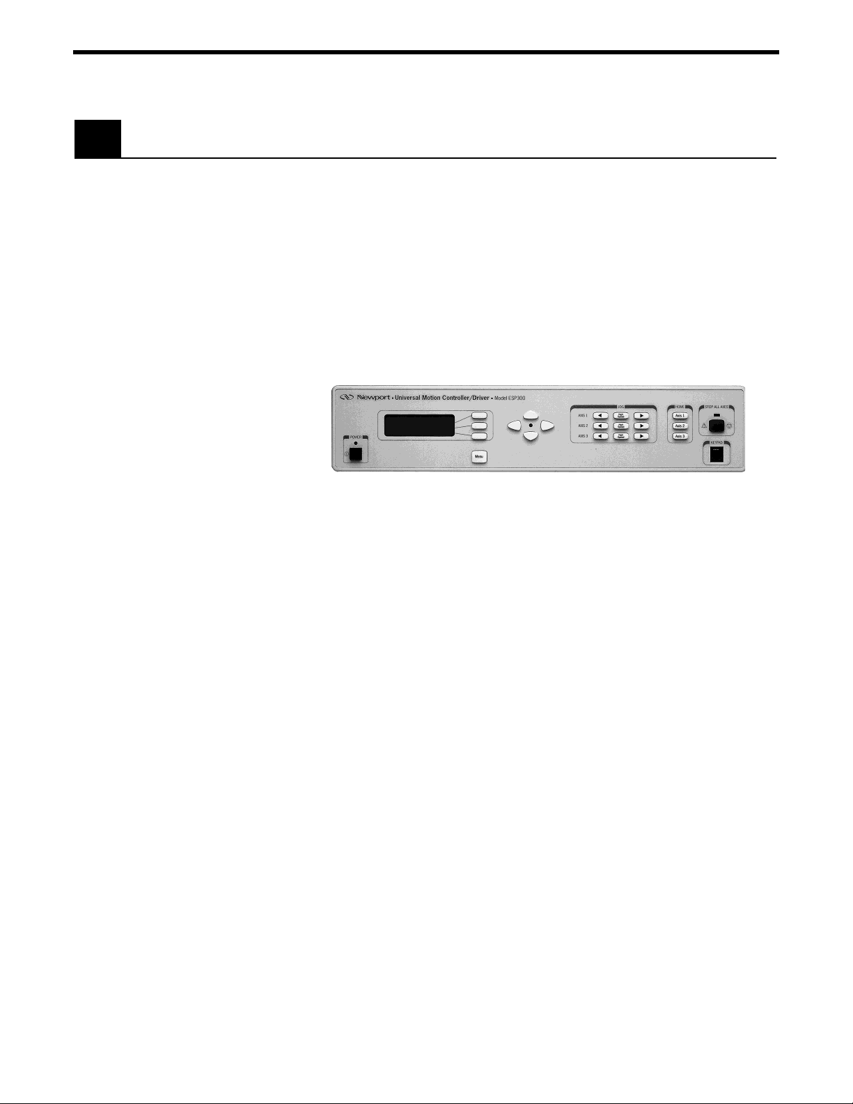
FRONT PANEL DISPLAY
A general view of the front panel is shown in (Figure 1.2). There are
two distinct areas: a display/menu section and a motion/home section
that allows simple manual motion sequence like JOG and HOMING.
X-Y buttons
Home Buttons
Stop All Axis
Power
Display
Window
Figure 1.2: ESP300 Front Panel with Displays
Menu
Button
BLANK FRONT PANEL
This version does not provide a display or local operation.
Power Section
The black push button type switch on the lower left corner is used to
turn power On or Off . The on state is indicated with a green LED
above the push-button.
1.4.4 Rear Panel Description
NOTE
See Appendix C for pin-outs.
AXIS CONNECTORS (AXIS 1 – AXIS 3)
J og Buttons
Keypad
Connector
There are up to three 25-pin D-Sub connectors on the rear panel, one
for each axis. Unused axes have blank panels.
Section 2 – Modes of Operation 1-9
Page 24
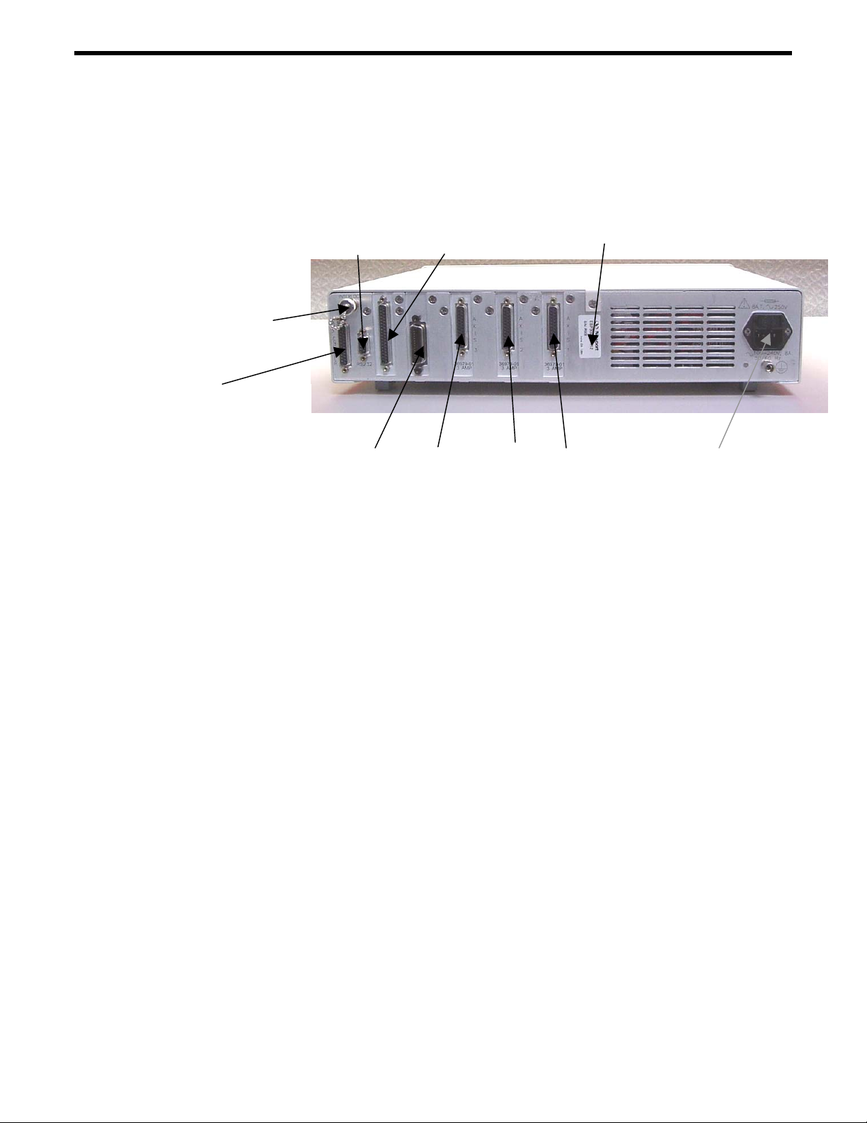
+/GPIO CONNECTOR
This is a 37-pin D-Sub connector used for general purpose, digital
Input/Output signals. A variety of commands are available to control
these ports. See Section 3, Remote Mode and Appendix C for
Connector Pin Outs.
Serial No. Label
Motor
Interlock
AUX Encoder
RS232-C
GPIO
IEEE-488 (optional)
Axis 3 Axis 2 Axis 1
Axis Connectors
Power Entry
Module
Figure 1.3: Rear Panel of the ESP300 (400 Watt chasse shown)
AUXILIARY ENCODER
This 25 pin D-Sub connector provides input for 3 auxiliary encoder
channels (axis 4, 5, 6). For signal description, see Section C.1.4.
These channels can be used for master-slaving (see Section 4.2),
trackball and other applications. Additionally, 4 digital I/O pins are
provided (See Section C.1.2).
MOTOR INTERLOCK CONNECTOR
The coaxial connector provides remote motor power interlock
capability. One or more external switches can be wired to remotely
inhibit the motor power in a way similar to the Stop All button on the
front panel.
The controller is shipped with a mating connector that provides the
necessary wiring to enable proper operation without an external
switch.
RS232-C CONNECTOR
The RS232-C interface to a host computer or terminal is made
through this 9 pin D-Sub connector. The pin out enables the use of an
off-the-shelf, pin-to-pin cable.
IEEE-488 CONNECTOR
1-10 Section 1 - Introduction
Page 25

1.5 System Setup
This is a standard 24 pin connector to interface with a standard
IEEE-488 device.
Note:
This is an optional feature.
POWER ENTRY MODULE
The power entry section on the right side of the rear panel provides a
standard IEC 320 inlet, a fuse holder, and a binding post to ground the
controller if the main power supply wiring does not provide earth
ground terminals.
This section guides the user through the proper set-up of the motion
control system.
Carefully unpack and visually inspect the controller and stages for
any damage.
Place all components on a flat and clean surface.
1.5.1 Line Voltage
The controller can operate from 100-240VAC, ±10%, at a
1.5.2 First Power ON
Plug the AC line cord supplied with the ESP300 into the power entry
module on the rear panel.
Do not block AC line cord entry area for disconnecting purpose.
Plug the AC line cord into the AC wall-outlet.
Push in the POWER switch on the lower left side of the front panel.
Shortly after the power is switched on, the ESP300 with front panel
display will perform a start-up sequence as described below.
NOTE
frequency of 50/60 Hz.
CAUTION
• Momentarily display: "Newport ESP300" and the Firmware
Version
Section 2 – Modes of Operation 1-11
Page 26

1.6 Quick Start
• Momentarily show the stage type that is connected. Since there
should be no stages connected at this point, the "NO STAGE"
message is displayed for all axes.
NOTE
Any time you call for technical support, the firmware version is
essential to trouble-shoot a problem. It is displayed every time the
controller power is turned on. Users of the blank front panel can
query the version with the "VE" command
(see Section 3, Remote Mode).
This section serves as a quick start for ESP300 with front panel
display only.
The following paragraphs guide you through a very basic motion
sequence that verifies that the system is working properly.
1.6.1 Connecting Motion Devices
NOTE
Never connect/disconnect stages while the ESP300 is powered on.
Power the ESP300 off.
If an ESP motion control system was purchased, all necessary
hardware for set-up is included.
With ESP compatible stages, the configuration of each axis is
identified automatically by the ESP300 at power up. ESP compatible
stages are visually identified with a blue "ESP Compatible" sticker,
on the stage.
Carefully connect one end of the supplied cables to the stage and the
other end to the appropriate axis connector on the rear of the
controller. Secure both connectors with the locking thumb-screws.
1-12 Section 1 - Introduction
Page 27

H
Users of the ESP300 with blank front panel can skip to Section 3,
Remote Mode.
1.6.2 Motor On
After the controller and the stages are connected as described, the
motors can be powered on.
Make sure that the motion devices are placed on a flat surface and
their full travel is not obstructed.
CAUTION
Be prepared to quickly turn the motor power off by pressing the
STOP ALL button or power switch if any abnormal operation is
observed.
After the power switch is pushed in, the controller performs the startup sequence as described in Section 1.5.2.
The default state after start-up is motor power off.
To apply power to the motors, press the button on the right of the
display to enable power for the respective axis. The ON state of the
motor power is indicated on the display. Blank Front Panel must use
external interface to enable motor power.
1.6.3 Homing
HOME Search
The HOME Search routine is a sequence of motion segments through
which the controller determines the exact location of a home (origin)
switch. A detailed description of the algorithm can be found in the
Motion Control Tutorial (Section 5).
It is recommended that the user perform a home search routine
after each controller power-on. The controller must know the
exact initial position of the motion device not only to accurately
repeat a motion sequence (program) but also to prevent it from
NOTE
hitting the travel limits (limit switches).
To perform a home search routine, press the home function key for
the respective axis.
Section 2 – Modes of Operation 1-13
Page 28
The display will indicate that a home routine is in progress with
to the left of the axis number.
NOTE
The position value is reset at the home position.
Only one axis can be homed at a time; i.e., even if multiple homing
commands are issued, the prior axis has to finish homing before the
second can start homing.
1.6.4 First Jog
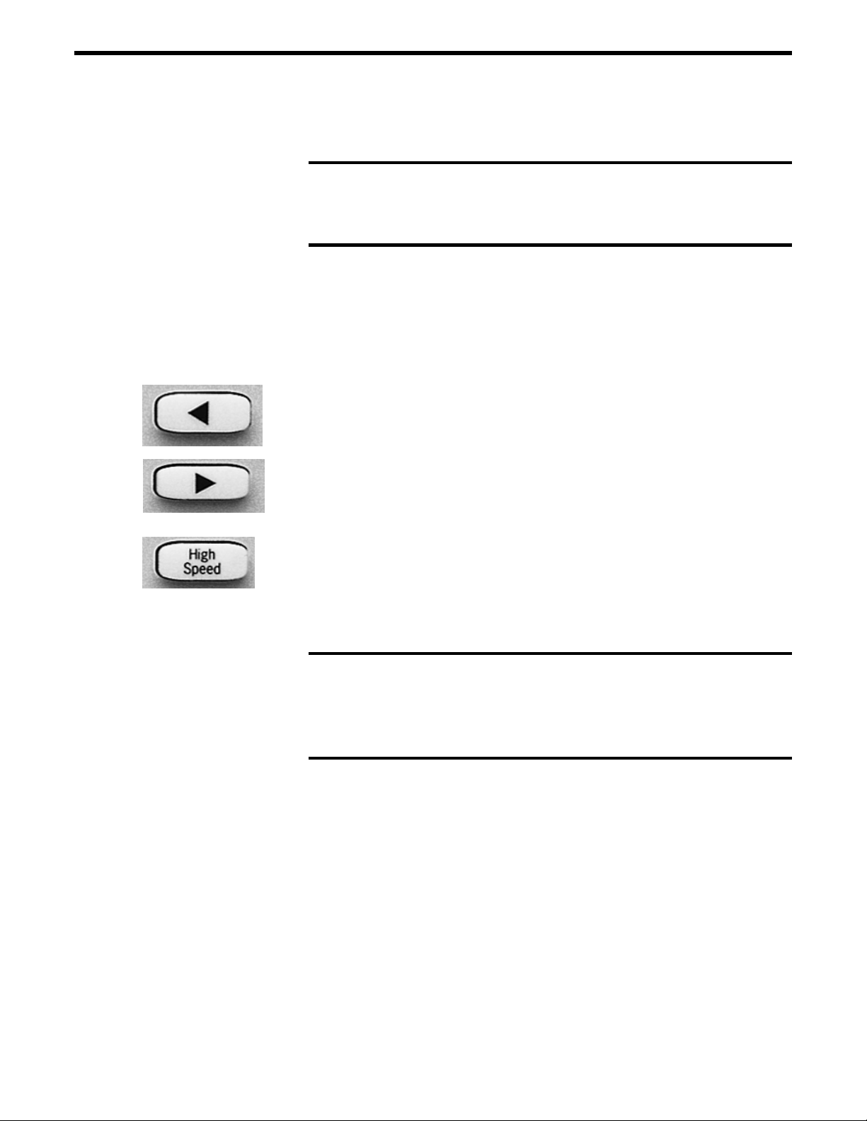
If left jog key is pressed, the selected axis will move slowly in the
negative direction. To move a single step at a time, press this switch
once. See Section 2.2.4 for details.
If right jog key is pressed, the selected axis will move slowly in the
positive direction. To move a single step at a time, press this switch
once. See Section 2.2.4 for details.
If the HIGH SPEED key between the jog keys is pressed
simultaneously with one of the jog keys, the axis will jog fast in the
selected direction. See Section 2 for setting of high speed rate.
At this point, you may proceed to Section 2 of this manual, to get
familiar with the controller and the local motion modes.
NOTE
Remember that only motions inside the software travel limits are
allowed (see 'SL' command in Section 3, Remote Mode). Any
move outside these limits will be ignored.
1-14 Section 1 - Introduction
Page 29

This page is intentionally left blank.
Section 2 – Modes of Operation 1-15
Page 30

Page 31

Section 2 – Modes of Operation
2.1 Overview of Operating Modes
The ESP300 can be operated in two basic modes:
• LOCAL mode
• REMOTE mode
2.1.1 LOCAL Mode
This mode is applicable only if your unit is equipped with the optional
front panel display. If your ESP300 is equipped with the blank front
panel, you may skip to the REMOTE Mode Section 3.
In LOCAL Mode the user has access to a sub-set of the ESP300
command set. In this Mode, the ESP300 is controlled by pressing the
menu key and axis push-buttons on the front panel.
Using this mode, the user can adjust motion parameters like velocity
and acceleration without using a computer or terminal.
See Section 2.2 for a detailed description of the front panel.
2.1.2 REMOTE Mode
In COMMAND Mode, the ESP300 receives motion commands
through one of its interfaces (IEEE488 or RS232-C) using a computer
or terminal. Additionally, an optional alphanumeric keypad with an
LCD display enables the user to access the full command set of the
ESP300 without the use of a computer interface (See Section 7.1.2).
In this mode, the ESP300 employs a set of over 100 commands.
Please refer to Section 3 (Remote Mode) for a detailed description of
the ESP300 command set.
NOTE
In Program Execution Mode, internally stored programs are executed
(See Section 3.1)
Section 2 – Modes of Operation 2-1
Page 32

2.2 Operation in LOCAL Mode
This section provides a detailed explanation of the LOCAL mode.
Typical parameters that can be set are velocity, acceleration, PID
values for DC motors, and many more. Please remember that all menu
items can also be accessed with remote commands (See Section 3,
Remote Mode).
2.2.1 Accessing the Menu
(Figure 2.1) shows the menu section of the front panel. The menu
listing can be accessed by pressing the Menu key at the bottom of the
display.
Verify Entered Value
De-select Menu Item
Cancel Entered
Value
Enter Menu
Figure 2.1: Menu Section
2.2.2 Navigating the Menu
Once in the menu listing, the x-y buttons shown on the left become
active, as indicated with a green LED in the center of the buttons.
With these four buttons, it is possible to access all available menu
items and change values where applicable.
Scroll Down
Menu OR
Decrement
Value
Scroll Up Menu OR
Increment Value
Select Menu Item
The Up and Down arrow buttons scroll through the available Menu
list.
The Right arrow button selects a menu item, the Left arrow button
de-selects a menu item.
2.2.3 Changing Values
This example serves as an illustration of how to change values within
a menu item.
2-2 Section 2 – Modes of Operation
Page 33

1. Press Menu to enter the menu listing.
2. Press the Down Arrow repeatedly until the cursor (diamond
shaped) is aligned with the SET VELOCITY menu item.
3. Press the Right Arrow button once. Now, a sub-menu list becomes
available.
4. Press the Right Arrow button to select the SET LO JOG VEL
menu item. The screen shown below is displayed at this time.
Figure 2.2: Menu Item
5. Press the Right Arrow button once. One digit on the display
flashes at this point indicating that it can be changed. The digit
can be incremented with the Up Arrow button or decremented
using the Down Arrow button. Other digits can be changed
similarly.
6. The set value can now be validated by pressing the OK button or
cancelled by pushing the CX button. Also, if you choose to exit
this menu item with the Left Arrow key, the set value will also be
valid.
2.2.4 Motion from the Front Panel
As shown in (Figure 2.3), the right side of the front panel
accommodates simple manual notion capabilities.
Move in
Negative
High Speed
Move with
Sop All Motion
Move in
Positive
Home
Stage
Connector for
Remote Keypad
Figure 2.3: Motion from the Front Panel Displayed
Section 2 – Modes of Operation 2-3
Page 34

Move in Negative Direction with low speed. This button can be
programmed to cause motion in user definable increments or to move
as long as it is pressed. See SET JOG MODE and SET VELOCITY
menu items in Section 2.2.5.
Move in Positive Direction with low speed. This button can be
programmed to cause motion in user definable increments or to move
as long as it is pressed. See SET JOG MODE and SET VELOCITY
menu items in Section 2.2.5.
Move with High Speed. This button is active only when pushed
simultaneously with either move button above. See SET VELOCITY
menu items in Section 2.2.5.
Home Respective Axis. See SET HOME MODE and SET
VELOCITY menu items in Section 2.2.5.
Stop All Motion. When this button is pressed, all motion is stopped
and the red LED above the button is illuminated temporarily. This
button is equivalent to the Interlock connector on the rear of the unit.
The LED is also illuminated when the interlock connector on the rear
of the unit is activated. See ZE command in Section 3: Remote Mode,
for further information.
An optional handheld keypad can be connected to the ESP300
through this receptacle. Refer to Section 7: Optional Equipment, for a
detailed description of the keypad.
2-4 Section 2 – Modes of Operation
Page 35

2.2.5 Detailed Description of Menu Items
TOP OF MENU
GET ERRORS
This menu item is only displayed if there is
an error in the queue.
Note
RESET POSITION
RUN PROGRAMM
SET VELOCITIES
SET LO JOG VEL
SET HIGH JOG VEL
SET HOME VEL
SET ACCEL/DECEL
SET JOG MODE
SET HOME MODE
SET PID
GET STAGE MODEL
GET RS232 CONFIG.
SAVE PARAMETERS
SET ACCELERATION
SET DECELERATION
RUN
INCREMENT
SW / INDEX
SW
SET KP
SET KI
SET KD
SET IL
SET FE
Section 2 – Modes of Operation 2-5
Page 36

GET ERRORS
This menu item allows the user to get the errors that are stored in the
error queue. The error queue can store up to 10 errors. If the number
of errors exceeds ten, the oldest errors are created.
TE or TB - Tell error or Tell buffer
RUN PROGRAM
Programs can be entered or downloaded to the ESP300 through its
standard interfaces (IEE-488 or RS-232). The ESP300 is capable of
storing up to 99 different programs in its non-volatile program
memory (25KB total). This menu allows execution of any of the
stored programs.
1EX - Execute program 1
SET VELOCITIES
This menu makes it possible to change velocities that are used with
the jog and home search buttons. The following sub-menus are
available:
SET LOW JOG VEL
Sets the velocity of the stage when either jog button is pushed.
JL - Set low jog velocity
SET HI JOG VEL
Sets the velocity of the stage when either jog button is pushed
simultaneously with the High Speed button.
JH - Set high jog velocity
2-6 Section 2 – Modes of Operation
Page 37

SET HOME VEL
Sets the velocity used during homing sequences. Refer to Section
1.6.3 for details on homing.
OH - Set home velocity
SET ACCEL/DECEL
This menu makes it possible to change acceleration and deceleration
that are used with the jog and home search buttons. The following
sub-menus are available:
SET ACCELERATION
Sets the acceleration that is used to accelerate to the desired velocity
when the jog buttons are used.
AC - Set Acceleration
SET DECELERATION
Sets the deceleration that is used to decelerate to the standstill when
the jog buttons are released.
AG - Set Deceleration
SET JOG MODE
Sets the mode used when either jog button is pressed. There are two
modes:
RUN
In this mode, the stage moves as long as either jog button is pressed.
INCR value
In this mode, the stage moves an incremental distance determined by
value when either jog button is pressed.
PR - Move Relative
Section 2 – Modes of Operation 2-7
Page 38

SET HOME MODE
This menu allows the user to choose between two homing modes.
Please refer to Section 5.4.3 for a detailed description of homing.
Please note that this menu only selects the homing method, but does
not initiate a home search. Home searches are initiated by pressing the
HOME button for the respective axis.
The following sub-menus are available:
SW
SW home search means the controller returns the stage to a position
determined by the home switch only. No index pulse is required.
OR2 - Set Home Mode to Switch only
SW/INDEX
SW/Index home search means the controller returns the stage to a
position determined by the home switch in connection with an index
pulse.
OR1 - Set Home Mode to Switch/Index
POSITION 0
Moves to zero position count.
OR0 - Set Home Mode 0
SET PID
This menu allows the user to modify the digital PID filter. All ESP
compatible motion devices offered with the ESP300 have a set of
conservative PID parameters that are loaded when the controller is
powered up.
To change them, some knowledge of motion control loops is needed.
Therefore, it is not recommended to modify the pre-set values before
reading some general guidelines in Section 6: Servo Tuning.
The following sub-menus are available:
2-8 Section 2 – Modes of Operation
Page 39

SET KP
Sets the integral gain of the digital PID filter.
KP - Set proportional gain
SET KI
Sets the integral gain of the digital PID filter.
KI - Set integral gain
SET KD
Sets the derivative gain of the digital PID filter.
KD - Set derivative gain.
SET IL
Sets the limit for the integrated value due to the integral gain KI factor
of the digital PID filter.
IL - Set integration limit
SET FE
Sets the maximum following error before motion is aborted.
FE - Set following error
GET STAGE MODELS
This menu allows the user to retrieve the model numbers of the stages
that are connected to the respective axes.
ID - Get stage identifier
Section 2 – Modes of Operation 2-9
Page 40

GET RS232 CONFIG
This menu allows the user to retrieve the current RS232 configuration
settings.
SAVE PARAMETERS
This menu allows the users to save all current settings (velocity,
acceleration, etc.) to the ESP300 non-volatile memory.
2-10 Section 2 – Modes of Operation
Page 41

Section 3 – Remote Mode
3.1 Programming Modes
The ESP is a command driven system. In general commands are a
series of two letter ASCII characters preceded by an axis number and
followed by parameters specific to the command. To communicate
with the ESP controller, a host terminal has to transfer ASCII character
commands according to the respective communication protocol (See
Section 3.2 for IEEE-488 or RS232 interfaces).
As briefly mentioned in Section 2, the ESP distinguishes between two
different programming modes:
COMMAND MODE
In this mode, the ESP controller provides a command input buffer
enabling the host terminal (e.g., PC) to download a series of
commands and then proceed to other tasks while the ESP controller
processes the commands.
As command characters arrive from the host terminal, they are placed
into the command buffer. When a carriage-return (ASCII 13 decimal)
terminator is received, the command is interpreted. If the command is
valid and its parameter is within the specified range, it will be
executed. If the command contains an error, it will not be executed and
a corresponding error message will be stored in the error buffer.
NOTE
The ESP power up state is command mode.
An example of a typical command sequence is shown below:
Example 1:
1PA + 30 move axis 1 to absolute position 30 units
1WS wait for axis 1 to stop
2PR-10 move axis 2 to relative position 10 units
Section 3 − Remote Mode 3-1
Page 42

Assuming that axis 1 and 2 are configured, Example 1 instructs the
ESP controller to move axis 1 to absolute position +30 units, wait for
it to stop, and then move axis 2 motor to relative –10 units.
Note that a command prefix identifies the axis or group that should
execute a command. Commands received without an axis prefix
generate an error. If a command is referenced to a non-existing axis, an
error is also generated. See Section 3.4 for further details on the
command syntax.
Also note that it is necessary to explicitly instruct the ESP controller
with the WS (Wait for Stop) command to wait for axis 1 motion to
stop. This is necessary because the ESP controller executes commands
continuously as long as there are commands in the buffer unless a
command is fetched from the buffer that instructs the controller to
wait. Executing a move does not automatically suspend command
execution until the move is complete. If the WS command were not
issued in Example 1, the controller would start the second move
immediately after the first move begins and simultaneously move axis
1 and axis 2.
NOTE
Unless instructed otherwise, the ESP controller executes
commands in the order received without waiting for completion
of previous commands.
Remember that commands must be terminated with a carriage-return
(ASCII 13 decimal). Until a terminator is received, characters are
simply kept in contiguous buffer space without evaluation.
Example 2:
1PA+30; 1WS; 2PR-10
Example #1 and Example #2 perform the same operations. In
Example #2 however, semicolons are used in place of carriage-returns
as command delimiters, keeping the ESP controller from interpreting
any commands on that line until the carriage-return terminator is
received at the very end of the string.
3-2 Section 3 – Remote Mode
Page 43

PROGRAM EXECUTION MODE
The ESP controller also implements an internal program execution
mode that enables the user to store up to 100 programs in a 64kB nonvolatile memory.
Even while executing stored programs, the ESP controller maintains
open communication channels so that the host terminal can continue to
direct the ESP to report any desired status, and even execute other
motion commands.
Let’s illustrate program execution mode using the previous example:
Example 3:
EP invoke program entry mode
1PA+30 enter program
1WS
2PR-10
QP exit program entry mode
1EX execute compiled program #1
As shown above, the sequence of commands has to be downloaded
into the ESP controller program memory without inadvertently
executing them. To facilitate this, the system provides the EP (Enter
Program) command; characters received thereafter are redirected to
program memory. Command syntax and parameters are not evaluated
(even after the carriage-return). Instead, they are treated as a series of
characters to be stored in contiguous memory.
Section 3 – Remote Mode 3-3
Page 44

3.2 Remote Interfaces
In this manual, Remote Interface refers to the two communication
interfaces that the controller can use to communicate with a computer
or a terminal via commands in ASCII format. It is not called a
Computer Interface since any device capable of sending ASCII
characters can be interfaced with the controller.
The remote interface should not be confused with the General Purpose
Input/Output (digital I/Os, a.k.a. GPIO).
3.2.1 RS-232C Interface
HARDWARE CONFIGURATION
The serial (RS-232C) communication interface on the ESP controller
is accessed through the 9 pin Sub-D connector located on the rear
panel. The pin out is designed to interface directly with an IBM PC or
compatible computer, using a straight through cable.
Appendix C shows the pin out of the RS-232C connector and different
cable types that may be used to interface to a computer.
COMMUNICATION PROTOCOL
The RS-232C interface must be properly configured on both devices
communicating. A correct setting is one that matches all parameters
(baud rate, number of data bits, number of stop bits, parity type and
handshake type) for both devices.
NOTE
The ESP RS-232C configuration is fixed at 8 data bits, no parity,
and 1 stop bit (Baud rate factory default = 19200) - can not be
changed by user.
To prevent buffer overflow when data is transferred to the ESP
controller input buffer, a CTS/RTS hardware handshake protocol is
implemented. The host terminal can control transmission of characters
from the ESP by enabling the Request To Send (RTS) signal once the
controller’s Clear To Send (CTS) signal is ready. Before sending any
further characters, the ESP will wait for a CTS from the host.
As soon as its command buffer is full, the controller de-asserts CTS.
Then, as memory becomes available because the controller reads and
executes commands in its buffer, it re-asserts the CTS signal to the
host terminal.
3-4 Section 3 – Remote Mode
Page 45

3.2.2 IEEE-488 Interface
HARDWARE CONFIGURATION
A typical IEEE-488 setup consists of a controller (host terminal) and
several devices connected to the bus. All devices are connected in
parallel to the data lines, data management and synchronization lines.
As a result of this type of connection, each device on the bus must
have a unique address so that the controller can selectively
communicate with it.
The address can be set through the optional front panel display or with
the SA (set address) command.
(Note: that the factory default is address 1)
COMMUNICATION PROTOCOL
The IEEE-488 interface is implemented on the motion controller
somewhat differently from a typical instrument because the standard
IEEE-488.2 command set and command format are inadequate for a
complex motion control. Since the ESP controller has its own
language and command set, the IEEE-488 interface is used only as a
communication port. The extended protocol is not supported.
The ESP controller has an ASCII command set and also outputs
system status in ASCII format. It features a command input buffer. If
the buffer fills up, the ESP will not allow further communication until
memory becomes available to accept new characters.
To send a command to the ESP controller, use the command specific
to your IEEE-488 terminal [e.g., output (ASCII)].
If the host terminal asks the controller for a response [e.g., input
(ASCII)] and no response is obtained, the controller will eventually
will time-out.
USE OF SRQ LINE
The ESP controller can be instructed to generate an IEEE-488 service
request (SRQ) upon processing the RQ command. This allows the user
to generate SRQs anywhere within the ESP command stream thereby
facilitating efficient event synchronization capability with the host
computer.
The following example illustrates the use of the RQ command:
Section 3 – Remote Mode 3-5
Page 46

1PR10; 1WS100; 2PR10; 3PR10; 3WS100; RQ
In the above example, the SRQ line is asserted only after execution of
the sequence preceding the RQ command is finished.
SERIAL POLL
When the IEEE-488 controller senses a service request on the bus, it
creates an interrupt to the application program (if configured to do so).
The application program must contain a service routine for this
interrupt. First, the program must determine which device on the bus
generated the service request. This is usually achieved with a function
called Serial Poll. The exact syntax for the serial poll command
depends on the IEEE-488 controller.
Using that interrupt service routine, a serial poll command can be
issued to each device. The device polled at each instance will respond
with a status byte. Bit 6 of the status byte indicates whether a specific
device (i.e., ESP controller) generated the service request or not. Bits 0
through 5 are under user control and are set with the RQ command.
For example, command “RQ5” sets bits 0 and 2. This is useful in
helping the application program determine which RQ in a program
with multiple RQs generated the SRQ.
3.3 Software Utilities
In order to communicate with the controller, the user must have a
terminal or a computer capable of communicating through RS-232C or
IEEE-488. One approach is to use a computer with communications
software that can emulate a terminal. Windows 95 provides an RS232
terminal emulation program named Hyper Terminal (HyperTrm.Exe)
located in Accessories. HyperTrm allows the user to send ASCII
commands to the motion controller. The user can even download text
files with stored programs. Additionally, it can be used to download
controller firmware for future upgrades.
For IEEE-488 communications National Instruments Inc. provides a
program named IBIC with their products that allow the user to send
and receive ASCII characters and download files. This could be useful
in determining that the interface is working.
3-6 Section 3 – Remote Mode
Page 47

3.4 Command Syntax
As mentioned previously, the ESP controller utilizes an ASCII
command set and also outputs system status in ASCII format.
Commands may be either upper or lower case characters.
The diagram below illustrates the ESP controller command syntax. As
indicated in this diagram, a valid command consists of three main
fields. The first field consists of a numerical parameter “xx”, the
second field consists of a two letter ASCII mnemonic, and the third
field consists of numerical parameter “nn”. The command is finally
terminated by a carriage return. For example, 3PA10.0 is a valid
command.
If a command does not require parameter “xx” and/or parameter “nn”,
that field may be skipped by leaving a blank character (space). For
example, BO1, 3WS, and AB are all valid commands.
If a command requires multiple parameters in the third field, all these
parameters must be comma delimited. For example, 1HN1,2 is a valid
command.
In a similar fashion, multiple commands can be issued on a single
command line by separating the commands by a semi-colon (;). For
example, 3MO; 3PA10.0; 3WS; 3MF is a valid command line.
parameter
"xx"
command
command
separator
( ; )
Figure 3.1: Command Syntax Diagram
parameter
"nn"
parameter
separator
( , )
terminator
(carriage
return)
NOTE
A controller command (or a sequence of commands) has to be
terminated with a carriage return character. However, responses
from the controller are always terminated by a carriage
return/line feed combination. This setting may not be changed. If
the IEEE interface is used, the IEEE controller has to be
configured to terminate the input (read) function when it senses
the line feed character.
Section 3 – Remote Mode 3-7
Page 48

3.4.1 Summary of Command Syntax
COMMAND FORMAT
The general format of a command is a two character mnemonic (AA).
Both upper and lower case are accepted. Depending on the command,
it could also have optional or required preceding (xx) and/or following
(nn) parameters.
BLANK SPACES
Blank spaces are allowed and ignored between parameters and
commands. For the clarity of the program and memory saving
considerations, use blank spaces with restraint. The following two
commands are equivalent.
2 PA 1000
2PA1000
but the first example is very confusing and uses more than twice the
memory.
COMMAND LINE
Commands are executed line by line. A line can consist of one or a
number of commands. The controller will interpret the commands in
the order they are received and execute them sequentially. This means
that commands issued on the same line are executed significantly
closer to each other than if they would be issued on separate lines. The
maximum number of characters allowed on a command line is 80.
SEPARATOR
Commands issued on the same line must be separated by semicolons (;).
Multiple parameters issued for the same command are separated by
commas (,).
TERMINATOR
Each command line must end with a line terminator, i.e., carriage
return.
XX
AA
nn
3-8 Section 3 – Remote Mode
Page 49

3.5 Command Summary
The controller understands many commands. The following tables list
all of them, sorted first by category and then alphabetically. The tables
also show the operating modes in which each command can be used.
The acronyms used in the tables have the following meaning:
IMM
IMMediate mode Controller is idle and the
commands will be executed
immediately.
PGM
ProGraM mode Controller does not execute but
stores all commands as part of a
program. EP activates this mode
and QP exits it.
MIP
Motion In Progress Controller executes command on
the specified axis while in
motion.
Section 3 – Remote Mode 3-9
Page 50

TABLE 3.5.1 – Command List by Category
In a PDF format you may click on a page number to automatically be connected to the corresponding Command Page
GENERAL MODE SELECTION
STATUS FUNCTIONS
Cmd. Description IMM PGM MIP Page
DP
DV
ID
Get target position
Get working speed
Get stage model and serial
♦
♦
♦
♦
♦
♦
333-
52
53
86
number
MD
PH
TB
TE
TP
TS
TV
TX
VE
XM
Get axis motion status
Get hardware status
Get error message
Get error number
Get position
Get controller status
Get velocity
Get controller activity
Get firmware version
Get available program memory
♦
♦
♦
♦
♦
♦
♦
♦
♦
♦
♦
♦
♦
♦
♦
♦
♦
♦
♦
♦
96
33- 109
138
3-
139
3-
141
3-
142
3-
143
3-
144
3-
150
3-
156
3-
MOTION & POSITION CONTROL
Cmd. Description IMM PGM MIP Page
AB
DH
MT
MV
MZ
OR
PA
PR
ST
Abort motion
Define home
Move to hardware travel limit
Move indefinitely
Move to nearest index
Origin searching
Move absolute
Move relative
Stop motion
♦
♦ ♦
♦
3-
♦ ♦ ♦
♦ ♦ ♦
♦ ♦
♦ ♦ ♦
♦ ♦ ♦
♦ ♦ ♦
♦ ♦ ♦
20
3-
49
99
3-
100
3-
102
3-
106
33- 108
112
33- 136
MOTION DEVICE PARAMETERS
Cmd. Description IMM PGM MIP Page
FE
FR
GR
QG
QI
QM
Set following error threshold
Full step resolution
Set gear ratio
Set gear constant
Motor current
Define motor type
♦ ♦ ♦
♦ ♦ ♦
♦ ♦ ♦
♦ ♦
♦ ♦
♦ ♦
3 3 3- 116
59
33- 61
62
3-
114
115
3-10 Section 3 – Remote Mode
Page 51

QR
QS
QT
QV
SI
Torque reduction
Set microstep factor
Define tachometer constant
Set motor voltage
Set master-slave jog update
♦ ♦ ♦
♦ ♦
♦ ♦
♦ ♦
3- 119
3 3-
♦ ♦ ♦
118
3-
120
121
3- 129
interval
3-
SK
Set slave axis jog velocity
♦ ♦ ♦
130
coefficients
SL
SN
SR
SS
SU
Set left limit
Set units
Set right limit
Set master-slave relationship
Set encoder resolution
♦ ♦ ♦
♦ ♦
♦ ♦
♦ ♦
♦ ♦
3- 133
3 3 3-
3-
131
134
135
137
PROGRAMMING
Cmd. Description IMM PGM MIP Page
3-
333-
33-
50
54
55
58
89
95
117
132
156
157
DL Define label
EO
EP
EX
JL
LP
QP
SM
XM
XX
Automatic execution on power on
Enter program download mode
Execute stored program
Jump to label
List program
Quit program mode
Save to non-volatile memory
Get available program memory
Delete a stored program
♦
♦
♦
3-
♦ ♦
♦
♦ ♦
♦
♦
♦
♦
3-
♦
3-
♦
3-
♦
♦
TRAJECTORY DEFINITION
Cmd. Description IMM PGM MIP Page
AC
AE
AG
AU
BA
CO
JH
JK
JW
OL
OH
OM
SH
UF
Set acceleration
Set e-stop deceleration
Set deceleration
Set maximum acceleration
Set backlash compensation
Set linear compensation
Set jog high speed
Set jerk rate
Set jog low speed
Set home search low speed
Set home search high speed
Set home search mode
Set home preset position
Update filter parameters
♦ ♦ ♦
♦ ♦ ♦
♦ ♦ ♦
♦ ♦ ♦
♦ ♦ ♦
♦ ♦ ♦
♦ ♦ ♦
♦ ♦ ♦
♦ ♦ ♦
♦ ♦ ♦
♦ ♦ ♦
♦ ♦ ♦
♦ ♦ ♦
♦ ♦ ♦
21
33- 23
26
33- 29
30
33- 41
87
3-
88
3-
90
3-
104
3-
103
3-
105
3-
128
3-
145
3-
Section 3 – Remote Mode 3-11
Page 52

VA
VB
VU
Set velocity
Set base velocity for step motors
Set maximum speed
♦ ♦ ♦
♦ ♦ ♦
♦ ♦ ♦
148
33- 149
152
3-
FLOW CONTROL & SEQUENCING
Cmd. Description IMM PGM MIP Page
333333-
50
89
122
125
153
154
155
DL
JL
RQ
SA
WP
WS
WT
Define label
Jump to label
Generate service request
Set device address
Wait for absolute position crossing
Wait for stop
Wait for time
♦
3-
♦ ♦
♦ ♦ ♦
♦ ♦ ♦
♦ ♦ ♦
♦ ♦ ♦
♦ ♦ ♦
I/O FUNCTIONS
Cmd. Description IMM PGM MIP Page
3-
BG
Assign DIO bits to execute stored
♦
♦
31
programs
BK
BL
BM
Assign DIO bits to inhibit motion
Enable DIO bits to inhibit motion
Assign DIO bits to notify motion
♦ ♦ ♦
♦ ♦ ♦
♦ ♦ ♦
333-
32
33
34
status
BN
Enable DIO bits to notify motion
♦ ♦ ♦
3-
35
status
BO
BP
BQ
DC
DD
DE
DF
DG
ES
SB
UL
UH
Set DIO Port Direction
Assign DIO for jog mode
Enable/disable DIO jog mode
Setup data acquisition
Get data acquisition done status
Enable/disable data acquisition
Get data acquisition sample count
Get acquisition data
Define event action command string
Set DIO state
Wait for DIO bit low
Wait for DIO bit high
♦ ♦ ♦
♦ ♦ ♦
♦ ♦ ♦
♦
♦
♦
♦
♦
♦
♦
♦
♦
♦
♦
♦
♦ ♦ ♦
♦
♦
333333333- 56
33- 147
3-
36
38
39
43
45
46
47
48
126
146
GROUP FUNCTIONS
Cmd. Description IMM PGM MIP Page
HA
HB
HC
HD
Set group acceleration
Read list of groups assigned
Move group along an arc
Set group deceleration
♦ ♦ ♦
♦
♦
♦ ♦ ♦
♦ ♦ ♦
3- 63
333-
65
66
68
3-12 Section 3 – Remote Mode
Page 53

HE
HF
HJ
HL
HN
HO
HP
HQ
Set group E-stop deceleration
Group motor power OFF 3Set group jerk
Move group along a line
Create new group
Group motor power ON
Get group position
Wait for group via point buffer
♦ ♦ ♦
♦ ♦ ♦
♦ ♦ ♦
♦ ♦ ♦
♦ ♦
♦ ♦ ♦
♦ ♦
♦ ♦ ♦
3-
33-
3-
333-
70
71
72
73
75
77
78
79
near empty
HS
HV
HW
HX
HZ
Stop group motion
Set group velocity
Wait for group motion to stop
Delete a group
Get group size
♦ ♦ ♦
♦ ♦ ♦
♦ ♦ ♦
♦ ♦ ♦
♦ ♦
33333-
80
81
82
84
85
DIGITAL FILTERS
Cmd. Description IMM PGM MIP Page
AF
Acceleration/Deceleration feed-
♦ ♦ ♦
3-
25
forward gain
CL
DB
KD
KI
KP
KS
UF
VF
Set closed loop update interval
Set position deadband
Set derivative gain Kd
Set integral gain Ki
Set proportional gain Kp
Set saturation coefficient Ks
Update Filter Parameters
Set velocity feed-forward gain
♦ ♦ ♦
♦ ♦ ♦
♦ ♦ ♦
♦ ♦ ♦
♦ ♦ ♦
♦ ♦ ♦
♦ ♦ ♦
♦ ♦ ♦
33333333-
40
42
91
92
93
94
145
151
MASTER-SLAVE MODE DEFINITION
Cmd. Description IMM PGM MIP Page
GR
SI
Set master-slave Ratio
Set master-slave jog update
♦ ♦ ♦
♦ ♦ ♦
3- 62
3-
129
interval
3-
SK
Set slave axis jog velocity
♦ ♦ ♦
130
coefficients
SS
Set master-slave mode
♦ ♦
3-
135
Section 3 – Remote Mode 3-13
Page 54

TABLE 3.5.2 – Command List – Alphabetical
In a PDF format you may click on a page number to automatically be connected to the corresponding Command Page
Cmd. Description IMM PGM MIP Page
AB
AC
AE
AF
AG
AP
AU
BA
BG
BK
BL
BM
BN
BO
BQ
CL
CO
DB
DC
DD
DE
DF
DG
DH
DL
DO
DP
DV
EO
EP
ES
EX
FE
Abort Motion
Set acceleration
Set e-stop deceleration
Set acceleration feed-forward gain
Set deceleration
Abort program
Set maximum acceleration and deceleration
Set backlash compensation
Assign DIO bits to execute stored programs
Assign DIO bits to inhibit motion
Enable DIO bits to inhibit motion
Assign DIO bits to notify motion status
Enable DIO bits to notify motion status
Set DIO port A, B, C direction
Enable DIO bits for jog mode
Set closed loop update interval
Set linear compensation
Set position deadband
Setup data acquisition
Get data acquisition done status
Enable/disable data acquisition
Get data acquisition sample count
Get acquisition data
Define home
Define label
Set DAC offset
Read desired position
Read desired velocity
Automatic execution on power on
Enter program mode
Define event action command string
Execute a program
Set maximum following error threshold
♦
♦
♦ ♦ ♦
♦ ♦ ♦
♦ ♦ ♦
♦ ♦ ♦
♦ ♦ ♦
♦ ♦ ♦
♦ ♦ ♦
♦
♦
♦ ♦ ♦
♦ ♦ ♦
♦ ♦ ♦
♦ ♦ ♦
♦ ♦ ♦
♦ ♦ ♦
♦ ♦ ♦
♦ ♦ ♦
♦ ♦ ♦
♦
♦
♦
♦
♦
♦
♦
♦
♦
♦
♦ ♦ ♦
♦ ♦ ♦
♦ ♦ ♦
♦
♦
♦
♦
♦
♦ ♦
♦
♦
♦
3-
♦
3-
♦ ♦ ♦
20
3-
21
3-
23
3-
25
33- 26
28
3-
29
3-
30
3-
31
3-
32
3-
33
3-
34
3-
35
3-
36
3-
39
3-
40
3-
41
3-
42
3-
43
3-
45
3-
46
3-
47
3-
48
3-
49
3-
50
3-
51
3-
52
3-
53
3-
54
3-
55
3- 56
58
3- 59
3-14 Section 3 – Remote Mode
Page 55

TABLE 3.5.2 – Command List – Alphabetical (Continued)
In a PDF format you may click on a page number to automatically be connected to the corresponding Command Page
Cmd. Description IMM PGM MIP Page
FP
FR
GR
HA
HB
HC
HD
HE
HF
HJ
HL
HN
HO
HP
HQ
HS
HV
HW
HX
HZ
ID
JH
JK
JL
JW
KD
KI
KP
KS
LP
MD
MF
MO
MT
MV
MZ
OH
OL
OM
Set position display resolution
Set full step resolution
Set master-slave reduction ratio
Set group acceleration
Read list of groups assigned
Move group along an arc
Set group deceleration
Set group e-stop deceleration
Group motor power off
Set group jerk
Move group along a line
Create new group
Group on
Read group position
Wait for group command buffer level
Stop group motion
Set group velocity
Wait for group motion stop
Delete group
Read group size
Read stage model and serial number
Set jog high speed
Set jerk rate
Jump to label
Set jog low speed
Set derivative gain
Set integral gain
Set proportional gain
Set saturation level of integral factor
List program
Read motion done status
Motor power off
Motor power on
Move to hardware travel limit
Move indefinitely
Move to nearest index
Set home search high speed
Set home search low speed
Set home search mode
♦ ♦ ♦
♦ ♦ ♦
♦ ♦ ♦
♦ ♦ ♦
♦
♦
♦ ♦ ♦
♦ ♦ ♦
♦ ♦ ♦
♦ ♦ ♦
♦ ♦ ♦
♦ ♦ ♦
♦ ♦
3-
♦ ♦ ♦
♦
♦
♦ ♦ ♦
♦ ♦ ♦
♦ ♦ ♦
♦ ♦ ♦
♦ ♦ ♦
♦ ♦ ♦
♦
♦
♦ ♦ ♦
♦ ♦ ♦
♦ ♦
♦ ♦ ♦
♦ ♦ ♦
♦ ♦ ♦
♦ ♦ ♦
♦ ♦ ♦
♦
♦
♦
♦
♦ ♦ ♦
♦ ♦ ♦
♦ ♦ ♦
♦ ♦ ♦
♦ ♦ ♦
♦ ♦ ♦
♦ ♦ ♦
♦ ♦ ♦
60
3-
61
3-
62
3-
63
33- 65
66
3-
68
3-
70
3-
71
3-
72
3-
73
3-
75
77
3-
78
3-
79
3-
80
3-
81
3-
82
3-
84
3-
85
3-
86
3-
87
3-
88
3-
89
3-
90
3-
91
3-
92
3-
93
3-
94
3-
95
33- 96
97
33- 98
99
33- 100
102
3-
103
3-
104
3-
105
3-
Section 3 – Remote Mode 3-15
Page 56

TABLE 3.5.2 – Command List – Alphabetical (Continued)
In a PDF format you may click on a page number to automatically be connected to the corresponding Command Page
Cmd. Description IMM PGM MIP Page
OR
PA
PH
PR
QD
QG
QI
QM
QP
QR
QS
QT
QV
RQ
RS
SA
SB
SH
SI
SK
SL
SM
SN
SR
SS
ST
SU
TB
TE
TJ
TP
TS
TV
TX
UF
UH
Search for home
Move to absolute position
Get hardware status
Move to relative position
Update motor driver settings
Set gear constant
Set maximum motor current
Set motor type
Quit program mode
Reduce motor torque
Set microstep factor
Set tachometer gain
Set average motor voltage
Generate service request
Reset the controller
Set device address
Set/get DIO port A, B, C bit status
Set home preset position
Set master-slave jog velocity update interval
Set master-slave jog velocity scaling coefficients
Set level travel limit
Save settings to non-volatile memory
Set axis displacement units
Set right travel limit
Define master-slave relationship
Stop motion
Set encoder resolution
Read error message
Read error code
Set trajectory mode
Read actual position
Get controller status
Get actual velocity
Get controller activity
Update servo filter
Wait for DIO bit high
♦ ♦
3-
♦ ♦ ♦
♦
♦
♦ ♦ ♦
♦ ♦
♦ ♦
♦ ♦
♦ ♦
♦
3-
3- 113
3 3 3-
♦ ♦ ♦
♦ ♦
♦ ♦
♦ ♦
3 3 3-
♦ ♦ ♦
♦
♦
♦ ♦ ♦
♦ ♦ ♦
♦ ♦ ♦
♦ ♦ ♦
♦ ♦ ♦
♦ ♦ ♦
♦
♦ ♦
♦ ♦
♦ ♦
3-
3 3 3-
♦ ♦ ♦
♦ ♦
♦
♦
♦ ♦
♦
♦
♦
♦
3-
♦
♦
3-
♦
♦
♦
♦
♦ ♦ ♦
♦
106
108
3-
109
3-
112
3-
114
115
116
117
118
3-
119
120
121
122
3-
123
3-
125
3-
126
3-
128
3-
129
3-
130
3-
131
3-
132
133
134
135
136
3-
137
138
3-
139
3-
140
3- 141
142
33- 143
144
33- 145
146
3-
3-16 Section 3 – Remote Mode
Page 57

TABLE 3.5.2 – Command List – Alphabetical (Continued)
In a PDF format you may click on a page number to automatically be connected to the corresponding Command Page
Cmd. Description IMM PGM MIP Page
UL
VA
VB
VE
VF
VU
WP
WS
WT
XM
XX
ZA
ZB
ZE
ZF
ZH
ZS
ZU
ZZ
Wait for DIO bit low
Set velocity
Set base velocity for step motors
Read controller firmware version
Set velocity feed-forward gain
Set maximum velocity
Wait for absolute position crossing
Wait for motion stop
Wait
Get available program memory
Delete a stored program
Set amplifier I/O configuration
Set feedback configuration
Set E-stop configuration
Set following error configuration
Set hardware limit configuration
Set software limit configuration
Get ESP system configuration
Set system configuration
♦
♦ ♦ ♦
♦ ♦ ♦
♦
♦
♦ ♦ ♦
♦ ♦ ♦
♦ ♦ ♦
♦ ♦ ♦
♦ ♦ ♦
♦
♦
♦ ♦
♦ ♦
♦ ♦
♦ ♦
♦ ♦
♦ ♦
♦
♦ ♦
♦
♦
3 3 3 3 3 3-
♦
3-
147
3-
148
3-
149
3-
150
33- 151
152
3-
153
3-
154
3-
155
3-
156
3-
157
3-
158
161
163
165
167
169
171
3-
173
3.6 Description of Commands
The extensive ESP controller command set exists to facilitate
application development for wide range of application and needs.
However, most simple positioning can be done with just a few
commands:
VA – set velocity
AC – set acceleration
AG – set deceleration
PR – position relative
PA – position absolute
TP – tell position
WS – wait for stop
Section 3 – Remote Mode 3-17
Page 58

NOTE
Most of the commands take an axis number as a parameter (xx).
For such commands, the valid range of axis number is from 1 to
MAX AXES, where MAX AXES is dependant on the
configuration of the ESP motion controller.
Commands related to coordinated motion and contouring (group
commands) take a group number as a parameter. For such
commands, the valid range of group number is from 1 to MAX
GROUPS, where MAX GROUPS is one-half the MAX AXES.
3-18 Section 3 – Remote Mode
Page 59

AA – (command mnemonic) (brief definition)
(motor type) *
USAGE ♦ IMM ♦ PGM ♦ MIP
(modes of operation)
SYNTAX xxAAnn (generic syntax format)
PARAMETERS
Description xx [ int ] -- (description of parameter)
Nn [float] -- (description of parameter)
(parameter could be integer number, floating point number, character or string)
Range xx -- (minimum value to maximum value)
nn -- (minimum value to maximum value)
Units xx -- (units description)
nn -- (units description)
Defaults xx missing: (default or error if parameter is missing)
out of range: (default or error if parameter is out of range)
nn missing: (default or error if parameter is missing)
out of range: (default or error if parameter is out of range)
DESCRIPTION (detailed description of the command)
Note:
(notes, reminders and things to consider when using the
command, if any)
RETURNS (Type, format and description of the return the command is generating, if any)
ERRORS (Error Code) – (description of errors the command could generate if misused)
REL. COMMANDS (brief definition of related commands)
EXAMPLE (Command Discussed) | (description)
(Other command) | (description)
(Controller return) | (description)
*(motor type) – if the command is specific for a motor type (DC or stepping) it will be labeled here, otherwise
this field is blank,
** The mode mnemonics has the following meanings:
(the diamonds mark which mode the command can be used in)
IMMediate mode – controller is in idle mode and the commands are executed immediately.
ProGraM mode – controller does not execute but stores all commands as part of a program.
Motion In Progress – controller is executing a motion on all or the specified axis.
Section 3 – Remote Mode 3-19
Page 60

AB abort motion
IMM PGM MIP
USAGE ♦ ♦
SYNTAX AB
PARAMETERS None.
DESCRIPTION This command should be used as an emergency stop. On reception of this
command, the controller invokes emergency stop event processing for each axis
as configured by ZE (e-stop event configuration) command.
By default axes are configured to turn motor power OFF, however, individual
axes can be configured to stop using emergency deceleration rate set by AE
command and maintain motor power.
It should be used only as an immediate command, not in a program.
Note:
This command affects all axes, however the action taken is determined by each
individual’s axis ZE command configuration.
RETURNS none
REL. COMMANDS ST - stop motion
AE - e-stop deceleration
ZE - e-stop deceleration
MF - motor OFF
MO - motor ON
EXAMPLE AB | used as an immediate command to stop all motion
3-20 Section 3 – Remote Mode
Page 61

AC set acceleration
IMM PGM MIP
USAGE ♦ ♦ ♦
SYNTAX xxACnn or xxAC?
PARAMETERS
Description xx [ int ] - axis number
nn [float] - acceleration value
Range xx - 1 to MAX AXES
N - 0 to the maximum programmed value in AU command
or ? to read current setting
Units xx - none
nn - predefined units / second2
Defaults xx missing: error 37, AXIS NUMBER MISSING
out of range: error 9, AXIS NUMBER OUT OF RANGE
nn missing: error 38, COMMAND PARAMETER MISSING
out of range: error xx11, MAXIMUM ACCELERATION
EXCEEDED
DESCRIPTION This command is used to set the acceleration value for an axis. Its execution is
immediate, meaning that the acceleration is changed when the command is
processed, even while a motion is in progress.
It can be used as an immediate command or inside a program. If the requested
axis is a member of a group, the commanded acceleration becomes effective only
after the axis is removed from the group. (Refer to Advanced Capabilities
section for a detailed description of grouping and related commands)
Avoid changing the acceleration during the acceleration or deceleration periods.
For better predictable results, change acceleration only when the axis is not
moving or when it is moving with a constant speed.
RETURNS If the “?” sign takes the place of nn value, this command reports the current
setting
REL. COMMANDS VA - set velocity
PA - execute an absolute motion
PR - execute a relative motion
AU - set maximum acceleration and deceleration
AG - set deceleration
EXAMPLE 2AU? | read maximum allowed acceleration/deceleration of axis # 2
Section 3 – Remote Mode 3-21
Page 62

10 | controller returns a value of 10 units/s2
2AC9 | set acceleration to 9 units/s2
2AG6 | set deceleration to 6 units/s2
2AU15 | set axis # 2 maximum acceleration/deceleration to 15 units/s2
2AU? | read maximum allowed acceleration & deceleration of axis # 2
15 | controller returns a value of 15 units
3-22 Section 3 – Remote Mode
Page 63

AE set e-stop deceleration
IMM PGM MIP
USAGE ♦ ♦ ♦
SYNTAX xxAEnn or xxAE?
PARAMETERS
Description xx [ int ] - axis number
nn [float] - e-stop deceleration value
Range xx - 1 to MAX AXES
nn - current normal deceleration value to 2e9 * encoder
resolution
or ? to read current setting
Units xx - none
nn - predefined units / second2
Defaults xx missing: error 37, AXIS NUMBER MISSING
out of range: error 9, AXIS NUMBER OUT OF RANGE
nn missing: error 38, COMMAND PARAMETER MISSING
out of range: error 1, PARAMETER OUT OF RANGE
DESCRIPTION This command is used to set the e-stop deceleration value for an axis. Its
execution is immediate, meaning that the e-stop deceleration value is changed
when the command is processed, even while a motion is in progress.
It can be used as an immediate command or inside a program. If the requested
axis is a member of a group, the commanded e-stop deceleration becomes
effective only after the axis is removed from the group. (Refer to Advanced
Capabilities section for a detailed description of grouping and related commands)
E-stop deceleration is invoked upon a local e-stop condition (e.g., front panel
Stop All pushbutton, Interlock, etc.) has occurred, if configured to do so, or if
the AB (abort motion) command is processed.
Note:
E-stop deceleration value cannot be set lower than the normal deceleration value.
Refer the description of “AG” command for range of deceleration values.
RETURNS If the “?” sign takes the place of nn value, this command reports the current
setting
REL. COMMANDS VA - set velocity
PA - execute an absolute motion
PR - execute a relative motion
Section 3 – Remote Mode 3-23
Page 64

AU - set maximum acceleration and deceleration
AG - set deceleration
AC - set acceleration
EXAMPLE 2AE? | read e-stop deceleration of axis # 2
100 | controller returns a value of 100 units/s2
2AE150 | set e-stop deceleration to 150 units/s2
3-24 Section 3 – Remote Mode
Page 65

AF set acceleration feed-forward gain
IMM PGM MIP
USAGE ♦ ♦ ♦
SYNTAX xxAFnn or xxAF?
PARAMETERS
Description xx [ int ] - axis number
nn [float] - acceleration feed-forward gain factor
Range xx - 1 to MAX AXES
nn- - 0 to 2e9, or ? to read current setting
Units xx - none
nn - none
Defaults xx missing: error 37, AXIS NUMBER MISSING
out of range: error 9, AXIS NUMBER OUT OF RANGE
nn missing: error 38, COMMAND PARAMETER MISSING
out of range: error xx2, PARAMETER OUT OF RANGE
DESCRIPTION This command sets the acceleration feed-forward gain factor Af. It is active for
any DC servo based motion device.
.
See the "Feed-Forward Loops" in Motion Control Tutorial section to
understand the basic principles of feed-forward.
Note:
The command can be sent at any time but it has no effect until the UF (update
filter) is received.
RETURNS If the “?” sign takes the place of nn value, this command reports the current
setting
REL. COMMANDS KI - set integral gain factor
KD - set derivative gain factor
KP - set proportional gain factor
KS - set saturation gain factor
VF - set velocity feed-forward gain
UF - update filter
EXAMPLE 3VF1.5 | set acceleration feed-forward gain factor for axis # 3 to 1.5
3AF? | report present axis-3 acceleration feedforward setting
0.9 | controller returns a value of 0.9
3AF0.8 | set acceleration feed-forward gain factor for axis # 3 to 0.8
3UF | update PID filter; only now the AF command takes effect
Section 3 – Remote Mode 3-25
Page 66

AG set deceleration
IMM PGM MIP
USAGE ♦ ♦ ♦
SYNTAX xxAGnn or xxAG?
PARAMETERS
Description xx [ int ] - axis number
nn [float] - acceleration value
Range xx - 1 to MAX AXES
Nn - to the maximum programmed value in AU command
or ? to read current setting
Units xx - none
Nn - predefined units / second2
Defaults xx missing: error 37, AXIS NUMBER MISSING
out of range: error 9, AXIS NUMBER OUT OF RANGE
nn missing: error 38, COMMAND PARAMETER MISSING
out of range: error xx11, MAXIMUM ACCELERATION
EXCEEDED
DESCRIPTION This command is used to set the deceleration value for an axis. Its execution is
immediate, meaning that the deceleration is changed when the command is
processed, even while a motion is in progress.
It can be used as an immediate command or inside a program. If the requested
axis is a member of a group, the commanded deceleration becomes effective only
after the axis is removed from the group. (Refer to Advanced Capabilities
section for a detailed description of grouping and related commands)
Avoid changing the deceleration during the acceleration or deceleration periods.
For better predictable results, change deceleration only when the axis is not
moving or when it is moving with a constant speed.
RETURNS If the “?” sign takes the place of nn value, this command reports the current
setting
REL. COMMANDS VA - set velocity
PA - execute an absolute motion
PR - xecute a relative motion
AC - set acceleration
AU - set maximum acceleration and deceleration
3-26 Section 3 – Remote Mode
Page 67

EXAMPLE 2AU? | read maximum allowed acceleration/deceleration of axis # 2
10 | controller returns a value of 10 units/s2
2AC9 | set acceleration to 9 units/s2
2AG6 | set deceleration to 6 units/s
2AG? | read maximum current deceleration of axis # 2
6 | controller returns a value of 6 units/s2
2
Section 3 – Remote Mode 3-27
Page 68

AP abort program
USAGE ♦ ♦ ♦
SYNTAX AP
PARAMETERS none
DESCRIPTION This command is used to interrupt a motion program in execution. It will not stop
It can be used as an immediate command or inside a program.
RETURNS none
REL. COMMANDS EX - execute a program
EXAMPLE 3EX | execute program # 3
AP | stop program execution
IMM PGM MIP
a motion in progress. It will only stop the program after the current command
line finished executing.
Inside a program it is useful in conjunction with program flow control
commands. It could, for instance, terminate a program on the occurrence of a
certain external event, monitored by an I/O bit.
•
•
•
3-28 Section 3 – Remote Mode
Page 69

AU set maximum acceleration and deceleration
IMM PGM MIP
USAGE ♦ ♦ ♦
SYNTAX xxAUnn or xxAU?
PARAMETERS
Description xx [ int ] - axis number
nn [float] - acceleration value
Range xx - 1 to MAX AXES
nn - 0 to 2e+9, or ? to read current setting
Units xx - none
nn - predefined units / second2
Defaults xx missing: error 37, AXIS NUMBER MISSING
out of range: error 9, AXIS NUMBER OUT OF RANGE
nn missing: error 38, COMMAND PARAMETER MISSING
out of range: error xx11, MAXIMUM ACCELERATION
EXCEEDED
error xx1, PARAMETER OUT OF RANGE
DESCRIPTION
RETURNS If the “?” sign takes the place of nn value, this command reports the current
REL. COMMANDS VA - set velocity
PA - execute an absolute motion
PR - execute a relative motion
AG - set deceleration
AC - et acceleration
EXAMPLE AU? | read maximum allowed acceleration/deceleration of axis # 2
10 | controller returns a value of 10 units/s2
2AC9 | set acceleration to 9 units/s2
2AG6 | set deceleration to 6 units/s2
This command is used to set the maximum acceleration and deceleration value for an
axis. This command remains effective even if the requested axis is member of a group.
In this case, two error messages "GROUP MAXIMUM ACCELERATION
EXCEEDED" or "GROUP MAXIMUM DECELERATION EXCEEDED" are generated
if the commanded value is less than group acceleration or deceleration respectively.
(Refer to Advanced Capabilities section for a detailed description of grouping and related
commands)
setting
2AU15 | set axis # 2 maximum acceleration/deceleration to 15 units/s2
2AU? | read maximum allowed acceleration & deceleration of axis # 2
15 | controller returns a value of 15 units/s
2
Section 3 – Remote Mode 3-29
Page 70

BA set backlash compensation
IMM PGM MIP
USAGE ♦ ♦ ♦
SYNTAX xxBAnn or xxBA?
PARAMETERS
Description xx [ int ] - axis number
nn [ float ] - backlash compensation value
Range xx - 1 to MAX AXES
nn - to distance equivalent to 10000 encoder counts
Units xx - none
nn - user units
Defaults xx missing: error 37, AXIS NUMBER MISSING
out of range: error 9, AXIS NUMBER OUT OF RANGE
nn missing: error 38, COMMAND PARAMETER MISSING
out of range: error 7, PARAMETER OUT OF RANGE
DESCRIPTION This command initiates a backlash compensation algorithm when motion
direction is reversed. The controller keeps track of the motion sequence and for
each direction change it adds the specified nn correction. Setting nn to zero
disables the backlash compensation.
NOTE: The command is affective only after a home search (OR) or define
home (DH) is performed on the specified axis.
RETURNS If “?” sign takes the place of nn value, this command reports the current setting.
REL. COMMANDS None
EXAMPLE 1BA0.0012 | Set backlash compensation value for axis #1 to 0.0012 units
1BA? | Query backlash compensation value for axis #1
0.0012 | Controller returns a value of 0.0012 units
1OR | Perform home search on axis #1
1PA10 | Move axis #1 to absolute 10 units
1PA0 | Move axis #1 to absolute 0 units
3-30 Section 3 – Remote Mode
Page 71

BG assign DIO bits to execute stored programs
IMM PGM MIP
USAGE ♦ ♦
SYNTAX xxBGnn or xxBG?
PARAMETERS
Description xx [ int ] - bit number used to trigger stored program execution
nn [ char ] - name of stored program to be executed
Range xx - 0 to 15
nn - None or ? to read current setting
Units None
Defaults xx missing: error 7, PARAMETER OUT OF RANGE
out of range: error 7, PARAMETER OUT OF RANGE
DESCRIPTION This command is used to assign DIO bits for initiating the execution of a desired
stored program. Execution of the stored program begins when the specified DIO
bit changes its state from HIGH to LOW logic level.
Note:
Each DIO bit has a pulled-up resistor to +5V. Therefore, all bits will be at HIGH
logic level if not connected to external circuit and configured as input.
RETURNS If the "?" sign takes the place of nn value, this command reports the current
setting.
REL. COMMANDS BO - Set DIO port A, B, direction
EP - Enter program mode
EX - Execute stored program
AP - Abort stored program execution
EXAMPLE BO 0H | Set DIO ports A and B to input
0 BG 1 | Start execution of a stored program 1 when DIO bit #0 changes
state from HIGH to LOW
Section 3 – Remote Mode 3-31
Page 72

BK assign DIO bits to inhibit motion
IMM PGM MIP
USAGE ♦ ♦ ♦
SYNTAX xxBKnn1, nn2 or xxBK?
PARAMETERS
Description xx [ int ] - axis number
nn1 [ int ] - bit number for inhibiting motion
nn2 [ int ] - bit level when axis motion is inhibited
Range xx - 1 to MAX AXES
nn1 - 0 to 15
nn2 - 0 = LOW and 1 = HIGH or ? to read current setting
Units None
Defaults xx missing: error 37, AXIS NUMBER MISSING
out of range: error 9, AXIS NUMBER OUT OF RANGE
nn1 missing: error 38, COMMAND PARAMETER MISSING
out of range: error xx1, PARAMETER OUT OF RANGE
nn2 missing: error 38, COMMAND PARAMETER MISSING
out of range: error xx1, PARAMETER OUT OF RANGE
DESCRIPTION This command is used to assign DIO bits for inhibiting the motion of a selected
axis. If the selected axis is already in motion, and DIO bit is asserted, e-stop is
executed per E-stop configuration (Refer "ZE" command for further details). If
the axis is not moving, any new move commands are refused as long as the DIO
bit is asserted. In either case, "DIGITAL I/O INTERLOCK DETECTED" error is
generated.
Note:
The direction of the DIO port (A, B or C) the desired bit belongs to, should be set
to "input" in order for the DIO bit to be read accurately. Refer "BO" command
for further details.
RETURNS If the "?" sign takes the place of nn value, this command reports the current
assignment.
REL. COMMANDS BL - Enable DIO bits to inhibit motion
BO - Set DIO port A, B direction
BM - Assign DIO bits to notify motion status
EXAMPLE BO 0H | Set DIO ports A, B to input
2BK 1, 1 | Use DIO bit #1 to inhibit motion of axis #2. This DIO bit should be
HIGH when axis #2 motion is inhibited
2BL 1 | Enable inhibition of motion using DIO bits for axis #2
2BK? | Query the DIO bit assignment for axis #2
1, 1 | The controller responds with the assigned values
3-32 Section 3 – Remote Mode
Page 73

BL enable DIO bits to inhibit motion
IMM PGM MIP
USAGE ♦ ♦ ♦
SYNTAX xxBLnn or xxBL?
PARAMETERS
Description xx [ int ] - axis number
nn [ int ] - disable or enable
Range xx - 1 to MAX AXES
nn - 0 = disable, and 1 = enable or ? to read current setting
Units None
Defaults xx missing: error 37, AXIS NUMBER MISSING
out of range: error 9, AXIS NUMBER OUT OF RANGE
nn missing: error 38, COMMAND PARAMETER MISSING
out of range: error xx1, PARAMETER OUT OF RANGE
DESCRIPTION This command is used to disable or enable motion inhibition of requested axes
through DIO bits.
RETURNS If the "?" sign takes the place of nn value, this command reports the current
status.
REL. COMMANDS BK - Assign DIO bits to inhibit motion.
BO - Set DIO port A, B direction
BM - Assign DIO bits to notify motion status
BN - Enable DIO bits to notify motion status.
EXAMPLE BO 0H | Set DIO ports A and B to input
2BK 1, 1 | Use DIO bit #1 to inhibit motion of axis #2. This DIO bit should be
HIGH when axis #2 motion is inhibited
2BL 1 | Enable inhibition of motion using DIO bits for axis #2
2BK? | Query the DIO bit assignment for axis #2
1, 1 | The controller responds with the assigned values
2BL? | Query the status of inhibiting motion for axis #2 through DIO
1 | The controller responds with 1 indicating feature is enabled
Section 3 – Remote Mode 3-33
Page 74

BM assign DIO bits to notify motion status
IMM PGM MIP
USAGE ♦ ♦ ♦
SYNTAX xxBMnn1, nn2 or xxBM?
PARAMETERS
Description xx [ int ] - axis number
nn1 [ int ] - bit number for notifying motion status
nn2 [ int ] - bit level when axis is not moving
Range xx - 1 to MAX AXES
nn1 - 0 to 15
nn2 - 0 = LOW and 1 = HIGH or ? to read current setting
Units None
Defaults xx missing: error 37, AXIS NUMBER MISSING
out of range: error 9, AXIS NUMBER OUT OF RANGE
nn1 missing: error 38, COMMAND PARAMETER MISSING
out of range: error xx1, PARAMETER OUT OF RANGE
nn2 missing: error 38, COMMAND PARAMETER MISSING
out of range: error xx1, PARAMETER OUT OF RANGE
DESCRIPTION This command is used to assign DIO bits for notifying the motion status –
moving or not moving – of a selected axis. When the selected axis is not moving,
the DIO bit state changes to the level specified with this command (refer
parameter nn2).
Note:
RETURNS If the "?" sign takes the place of nn value, this command reports the current
REL. COMMANDS BN - Enable DIO bits to notify motion status
BO - Set DIO port A, B direction
EXAMPLE BO 2H | Set DIO port A to input and B to output
2BM 9, 1 | Use DIO bit #9 to indicate motion status of axis #2. This DIO bit
should be HIGH when axis #2 is not moving
2BN 1 | Enable notification of motion using DIO bits for axis #2
2BM? | Query the DIO bit assignment for axis #2
9, 1 | The controller responds with the assigned values
Note:
The direction of the DIO port (A or B) the desired bit belongs to, should be set to
"output" in order for the DIO bit to be set accurately. Refer "BO" command for further
details.
If a motion feature, such as origin search, involves a sequence of moves, the motion
status will be set to not moving only after the entire sequence of moves has completed.
assignment.
3-34 Section 3 – Remote Mode
Page 75

BN enable DIO bits to notify motion status
IMM PGM MIP
USAGE ♦ ♦ ♦
SYNTAX xxBNnn or xxBN?
PARAMETERS
Description xx [ int ] - axis number
nn [ int ] - disable or enable
Range xx - 1 to MAX AXES
nn - 0 = disable, and 1 = enable or ? to read current setting
Units None
Defaults xx missing: error 37, AXIS NUMBER MISSING
out of range: error 9, AXIS NUMBER OUT OF RANGE
nn missing: error 38, COMMAND PARAMETER MISSING
out of range: error xx1, PARAMETER OUT OF RANGE
DESCRIPTION This command is used to disable or enable notification of requested axis' motion
status through DIO bits.
RETURNS If the "?" sign takes the place of nn value, this command reports the current
status.
REL. COMMANDS BM - Assign DIO bits to notify motion status
BO - Set DIO port A, B
BK - Assign DIO bits to inhibit motion
BL - Enable DIO bits to inhibit motion
EXAMPLE BO 2H | Set DIO port A to input and ports B to output
2BM 9, 1 | Use DIO bit #9 to indicate motion status of axis #2. This DIO bit
should be HIGH when axis #2 is not moving
2BN 1 | Enable notification of motion using DIO bits for axis #2
2BM? | Query the DIO bit assignment for axis #2
9, 1 | The controller responds with the assigned values
2BN? | Query the status of notifying motion status of axis #2 through
DIO bits
1 | The controller responds with 1 indicating feature is enabled
Section 3 – Remote Mode 3-35
Page 76

BO set DIO port A, B direction
IMM PGM MIP
USAGE ♦ ♦ ♦
SYNTAX BOnn or BO?
PARAMETERS
Description nn [ int ] - hardware limit configuration
Range nn - 0 to 03H (hexadecimal with leading zero(0)) on
ESP100 and ESP300
or ? to read current setting
Units nn - None
Defaults nn missing: error 38, COMMAND PARAMETER MISSING
out of range: error 7, PARAMETER OUT OF RANGE
DESCRIPTION This command is used to set digital I/O (DIO) port A, B, and C direction where
bit-0 corresponds to port A, bit-1 to port B, and bit-2 to port C. If any bit is set to
zero(0) then its corresponding port will become an input only. If any bit is set to
one(1) then its corresponding port will becomes an output only. Ports A and B
only are available on the ESP100 and ESP300.
A DIO within a port configured as an input can only report its present HIGH or
LOW logic level. Whereas a DIO bit within a port configured as an output can
set(1) or clear(0) the corresponding DIO hardware to HIGH or LOW logic level.
Reading the status of a port configured as output returns its present output status.
Note:
All direction bits are automatically zeroed, or cleared, after a system reset.
Therefore all DIO ports default to input by default.
Note:
Each DIO bit has a pulled-up resistor to +5V. Therefore, all bits will be at HIGH
logic level if not connected to external circuit and configured as input.
BIT# VALUE DEFINITION
*0 0 port A (DIO bit-0 through bit-7) assigned as input
0 1 port A (DIO bit-0 through bit-7) assigned as output
*1 0 port B (DIO bit-8 through bit-15) assigned as input
1 1 port B (DIO bit-8 through bit-15) assigned as output
RETURNS If the “?” sign takes the place of nn value, this command reports the current
setting in hexadecimal notation.
3-36 Section 3 – Remote Mode
* default setting after system reset
Page 77

REL. COMMANDS SB - set/clear DIO bits
EXAMPLE BO? | read DIO port direction configuration
0H | controller returns a value of 0H (all ports are input)
BO 1H | configure DIO port A as output
SB 0FFH | set all port A DIO output HIGH
Section 3 – Remote Mode 3-37
Page 78

BP assign DIO bits for jog mode
IMM PGM MIP
USAGE ♦ ♦ ♦
SYNTAX xxBPnn1,nn2 or xxBP?
PARAMETERS
Description xx [ int ] - axis number
nn1 [ int ] - bit number for jogging in negative direction
nn2 [ int ] - bit number for jogging in positive direction
Range xx - 1 to MAX AXES
nn
Units xx - none
nn
Defaults xx missing: error 37, AXIS NUMBER MISSING
out of range: error 9, AXIS NUMBER OUT OF RANGE
nn missing: error 38, COMMAND PARAMETER MISSING
out of range: error xx2, PARAMETER OUT OF RANGE
- 0 to 15
i
- none
i
DESCRIPTION This command is used to assign DIO bits for jogging axes in either negative or
positive directions.
RETURNS If "?" sign is issued along with command, the controller returns the DIO bits used
for jogging in negative and positive directions respectively.
REL. COMMANDS BO - enable usage of DIO bits for jogging axes
EXAMPLE 1BP3, 4 | set DIO bit #3 to jog axis #1 in negative direction and
DIO bit #4 to jog axis #1 in positive direction
1BP? | query the DIO bits assigned for jogging
3,4 | controller returns the bit assignment
1BQ1 | enable axis #1 jogging through DIO bits.
3-38 Section 3 – Remote Mode
Page 79

BQ enable DIO bits for jog mode
IMM PGM MIP
USAGE ♦ ♦ ♦
SYNTAX xxBQnn or BQ?
PARAMETERS
Description xx [ int ] - axis number
nn [ int ] - disable or enable
Range xx - 1 to MAX AXES
nn - 0 = disable, and 1 = enable
Units xx - none
nn - one
Defaults xx missing: error 37, AXIS NUMBER MISSING
out of range: error 9, AXIS NUMBER OUT OF RANGE
nn missing: error 38, COMMAND PARAMETER MISSING
out of range: error xx2, PARAMETER OUT OF RANGE
DESCRIPTION This command is used to disable or enable jogging of a requested axis through
DIO bits.
RETURNS If “?” sign is issued along with command, the controller returns the status of jog
through DIO bits.
REL. COMMANDS BP - assign DIO bits for jog mode
EXAMPLE 1BP3,4 | set DIO bit #3 to jog axis #1 in negative direction and
| DIO bit #4 to jog axis #1 in positive direction
1BP? | query the DIO bits assigned for jogging
3,4 | controller returns the bit assignment
1BQ1 | enable axis #1 jogging through DIO bits.
Section 3 – Remote Mode 3-39
Page 80

CL set closed loop update interval
IMM PGM MIP
USAGE ♦ ♦ ♦
SYNTAX xxCLnn or xxCL?
PARAMETERS
Description xx { int ] - axis number
nn [ int ] - closed loop update interval
Range xx - 0 to MAX AXES
nn - 0 to 60000
Units xx - none
nn - milliseconds
Defaults xx missing: error 37, AXIS NUMBER MISSING
out of range: error 9, AXIS NUMBER OUT OF RANGE
nn missing: error 38, COMMAND PARAMETER MISSING
out of range: error 7, PARAMETER OUT OF RANGE
DESCRIPTION This command is used to set the closed loop update interval for an axis. This will
Furthermore, note that encoder feedback and closed loop positioning must be
If "0" is used as an axis number, this command will set the specified interval to
be the time duration between position error corrections during closed loop
stepper positioning. Note that this command is effective only for steeper motors.
enabled for this command to be effective. Refer to feedback configuration (ZB)
command for enabling these features in the case of stepper motors.
all the axes.
RETURNS If "?" sign takes the place of nn value, this command reports the current setting.
REL. COMMANDS ZB - set feedback configuration
DB - set position deadband value
EXAMPLE 3ZB300 | enable encoder feedback and closed loop positioning of axis #3
3DB1 | set position deadband value to 1 encoder count
3DB? | query deadband value
1 | controller returns a value of 1 encoder count
3CL100 | set closed loop update interval to 100 milliseconds
3CL? | query closed loop update interval
100 | controller returns a value of 100 milliseconds
3-40 Section 3 – Remote Mode
Page 81

CO set linear compensation
IMM PGM MIP
USAGE ♦ ♦ ♦
SYNTAX xxCOnn or xxCO?
PARAMETERS
Description xx [ int ] - axis number
nn [ float ] - linear compensation value
Range xx - 1 to MAX AXES
nn - 0 to 2e+9
Units xx - none
nn - none
Defaults xx missing: error 37, AXIS NUMBER MISSING
out of range: error 9, AXIS NUMBER OUT OF RANGE
nn missing: error 38, COMMAND PARAMETER MISSING
out of range: error 7, PARAMETER OUT OF RANGE
DESCRIPTION This command allows users to compensate for linear positioning errors due to stage
inaccuracies. Such errors decrease or increase actual motion linearly over the travel
range.
The linear compensation value, nn is calculated according to the formula given below:
error
nn
=
travel
where,
travel = measured travel range
error = error accumulated over the measured travel range
Note:
The command is affective only after a home search (OR) or define home (DH) is
performed on the specified axis.
RETURNS
If “?” sign takes the place of nn value, this command reports the current setting.
REL. COMMANDS None
EXAMPLE If a stage has a travel range of 100 mm and it accumulates an error of 0.003 mm over the
complete travel range,
003.0
=nn
100
1CO0.00003 | Set linear compensation value for axis #1 to 0.00003
1CO? | Query linear compensation value for axis #1
0.00003 | Controller returns a value of 0.00003
1OR | Perform home search on axis #1
1PA10 | Move axis #1 to absolute 10 units
=
00003.0
Section 3 – Remote Mode 3-41
Page 82

DB set position deadband
IMM PGM MIP
USAGE ♦ ♦ ♦
SYNTAX xxDBnn or xxDB?
PARAMETERS
Description xx [ int ] - axis number
nn [ int ] - deadband value
Range xx - 0 to MAX AXES
nn - to 2e9
Units xx - none
nn - encoder counts
Defaults xx missing: error 37, AXIS NUMBER MISSING
out of range: error 9, AXIS NUMBER OUT OF RANGE
nn missing: error 38, COMMAND PARAMETER MISSING
DESCRIPTION
Note that this command is effective only during position regulation (holding position) as
Furthermore, note that encoder feedback and closed loop positioning must be enabled for
If “0” is used as an axis number, this command will set the specified deadband value to
RETURNS If “?” sign takes the place of nn value, this command reports the current setting.
REL. COMMANDS ZB - set feedback configuration
CL - set closed loop update interval
EXAMPLE ZB300 | enable encoder feedback and closed loop positioning of axis#3
3DB1 | set position deadband value to 1 encoder count
3DB? | query deadband value
3CL100 | set closed loop update interval to 100 milliseconds
3CL? | query closed loop update interval
100 | controller returns a value of 100 milliseconds
This command is used to set the position deadband value for an axis. Since a majority of
electro-mechanical systems have mechanical backlash or frictional hysterisis, closed-loop
positioning can at times lead to oscillation or limit cycling of the systems around a
desired position. In such situations, setting position deadband value judiciously can
avoid limit cycling of the systems.
opposed to moving.
this command to be effective. Refer to feedback configuration (ZB) command for
enabling these features in the case of stepper motors.
all the axes.
1 | controller returns a value of 1 encoder count
3-42 Section 3 – Remote Mode
Page 83

DC setup data acquisition
IMM PGM MIP
USAGE ♦ ♦
SYNTAX DCnn1,nn2,nn3,nn4,nn5,nn6
PARAMETERS
Description nn1 [ int ] - data acquisition mode
nn2 [ int ] - axis used to trigger data acquisition
nn3 [ int ] - data acquisition parameter 3
nn4 [ int ] - data acquisition parameter 4
nn5 [ int ] - data acquisition rate
nn6 [ int ] - number of data samples to be acquired
Range nn1 - 0: Start data acquisition immediately
1: Start data acquisition when trigger axis starts motion
2: Start data acquisition when trigger axis reaches slew
speed
nn2 - 1 to MAX AXES
nn3 - 0
nn4 - 0 to 7
nn5 - 0 to 1000
nn6 - to 1000
Units None
Defaults nn missing: error 38, COMMAND PARAMETER MISSING
out of range: error 7, PARAMETER OUT OF RANGE
DESCRIPTION
PARAMETER nn1: Data acquisition modes 0—2 support different ways in which
PARAMETER nn3: Set this value to 0.
PARAMETER nn4: This parameter is used to identify the position feedback channels
This command is used to setup data acquisition—analog data acquisition (ADC) as well
as acquisition of certain trace variables—using ESP motion controller.
position feedback data can be collected.
PARAMETER nn2: Data acquisition—is triggered by the motion of an axis specified
through this parameter. Exceptions to this requirement is in the case of data acquisition
mode 0. For this case enabling data acquisition is sufficient to start the data acquisition
process. For all other modes, two conditions—enabling of data acquisition and any mode
dependent conditions such as trigger axis starting motion or reaching slew speed—must
be met in order to start the data acquisition process.
to be collected. Please refer to table below.
Section 3 – Remote Mode 3-43
Page 84

nn4 Position feedback channels collected
0 none
1 channel 1
2 channel 2
3 channel 1 & 2
4 channel 3
5 channel 1 & 3
6 channel 2 & 4
7 channel 1,2,3
PARAMETER nn5: The rate at which data is to be acquired is specified through this
parameter. The rate specified is in multiples of the servo cycle rate. For example, a value
of 0 implies data acquisition every servo cycle, a value of 1 implies every other servo
cycle, and so on.
PARAMETER nn6: The number of samples of data to be acquired is specified through
this parameter. Data acquisition process is considered to be "done" only after the number
of samples specified by this parameter are acquired by the controller. The status of data
acquisition process may be found by issuing ASCII command, DD. Once the data
acquisition is done, ASCII command, DG may be used to collect the data from the
controller.
Note:
The controller responds with a servo cycle tick count along with every data sample
RETURNS None.
REL. COMMANDS DD - get data-acquisition done status
DE - enable / disable data-acquisition
DF - get data-acquisition status – number of samples collected
DG - get data-acquisition data
EXAMPLE DC1,1,0,4,1,500
nn1=1 : Start data acquisition when trigger axis start motion
collected.
nn2=1 : Trigger axis is 1
nn3=0
nn4=4 : Position feedback from channel 3
nn5=1 : Collect data entry often servo cycle
nn6=500 : Collect 500 samples
DE1 Enable data acquisition
DD Query data acquisition done status
1 = true 0 = false
If true,
DEO Disable data acquisition
DF Get data acquisition sample count
500 Controller responds with number samples collected
DG Get data collected
3-44 Section 3 – Remote Mode
Page 85

DD get data acquisition done status
IMM PGM MIP
USAGE ♦ ♦
SYNTAX DD
PARAMETERS none
DESCRIPTION This command returns the status of a data acquisition request.
RETURNS aa, where: aa = 1 for True, 0 for False
REL. COMMANDS DC - setup data acquisition request
DG - get acquired data
DF - data acquisition status, returns # of samples collected
DE - enable / disable data acquisition
EXAMPLE DC1,1,0,4,1,500
nn1=1 : Start data acquisition when trigger axis start motion
nn2=1 : Trigger axis is 1
nn3=0
nn4=4 : Position feedback from channel 3
nn5=1 : Collect data entry often servo cycle
nn6=500 : Collect 500 samples
DE1 Enable data acquisition
DD Query data acquisition done status
1 = true 0 = false
If true,
DEO Disable data acquisition
DF Get data acquisition sample count
500 Controller responds with number samples collected
DG Get data collected
Section 3 – Remote Mode 3-45
Page 86

DE enable/disable data acquisition
IMM PGM MIP
USAGE ♦ ♦
SYNTAX DEnn
PARAMETERS nn
Description nn [ int ] - True | False
Range nn - 1 for True, 0 for False
DESCRIPTION This command is used to enable / disable the data acquisition request.
Note:
This command cannot be issued when:
1. An axis is being homed (refer ASCII command, OR).
2. An axis is being moved to a travel limit (refer ASCII command, MT).
3. An axis is being moved to an index (refer ASCII command, MZ).
RETURNS None
REL. COMMANDS DC - setup data acquisition request
DG - get acquired data
DF - data acquisition status, returns # of samples collected
DD - data acquisition done status
EXAMPLE DC1,1,0,4,1,500
nn1=1 : Start data acquisition when trigger axis start motion
nn2=1 : Trigger axis is 1
nn3=0
nn4=4 : Position feedback from channel 3
nn5=1 : Collect data entry often servo cycle
nn6=500 : Collect 500 samples
DE1 Enable data acquisition
DD Query data acquisition done status
1 = true 0 = false
If true,
DEO Disable data acquisition
DF Get data acquisition sample count
500 Controller responds with number samples collected
DG Get data collected
3-46 Section 3 – Remote Mode
Page 87

DF get data acquisition sample count
IMM PGM MIP
USAGE ♦ ♦
SYNTAX DF
PARAMETERS none
DESCRIPTION This command returns the number of a data acquisition collected to the point of
this request.
RETURNS aa, where: aa = number of samples
REL. COMMANDS DC - setup data acquisition request
DG - get acquired data
DD - data acquisition done status
DE - enable / disable data acquisition
EXAMPLE DC1,1,0,4,1,500
nn1=1 : Start data acquisition when trigger axis start motion
nn2=1 : Trigger axis is 1
nn3=0
nn4=4 : Position feedback from channel 3
nn5=1 : Collect data entry often servo cycle
nn6=500 : Collect 500 samples
DE1 Enable data acquisition
DD Query data acquisition done status
1 = true 0 = false
If true,
DEO Disable data acquisition
DF Get data acquisition sample count
500 Controller responds with number samples collected
DG Get data collected
Section 3 – Remote Mode 3-47
Page 88

DG get acquisition data
IMM PGM MIP
USAGE ♦ ♦
SYNTAX DG
PARAMETERS None
DESCRIPTION This command is used to retrieve data acquired from a data acquisition request.
RETURNS This command returns byte wide binary data. Each four bytes represents one
DSP 32 bit word. The number of bytes returned depends on the setup request.
(See DC command).
REL. COMMANDS DC - setup data acquisition request
DE - enable / disable data acquisition
DF - data acquisition status, returns # of samples collected
DD - data acquisition done status
EXAMPLE DC1,1,0,4,1,500
nn1=1 : Start data acquisition when trigger axis start motion
nn2=1 : Trigger axis is 1
nn3=0
nn4=4 : Position feedback from channel 3
nn5=1 : Collect data entry often servo cycle
nn6=500 : Collect 500 samples
DE1 Enable data acquisition
DD Query data acquisition done status
1 = true 0 = false
If true,
DEO Disable data acquisition
DF Get data acquisition sample count
500 Controller responds with number samples collected
DG Get data collected
3-48 Section 3 – Remote Mode
Page 89

DH define home
IMM PGM MIP
USAGE ♦ ♦
SYNTAX xxDHnn
PARAMETERS
Description xx [ int ] - axis number
nn [float] - position value
Range xx - 1 to MAX AXES
nn - 0 to ± 2e+9
Units xx - none
nn - predefined units
Defaults xx missing: error 37, AXIS NUMBER MISSING
out of range: error 9, AXIS NUMBER OUT OF RANGE
nn missing: error 38, COMMAND PARAMETER MISSING
out of range: error xx2, PARAMETER OUT OF RANGE
DESCRIPTION This command is used to define current position, HOME position. This means
that the current position will be preset to the value defined by parameter ‘nn’.
RETURNS If the “?” sign takes the place of nn value, this command reports the current
setting
REL. COMMANDS OR - execute a home search cycle
EXAMPLE 3OR1 | perform a home search on axis # 3
3DH | define current position on axis # 3 HOME as 0 units
3DH 20.0 | define current position on axis # 3 HOME as 20.0 units
•
•
•
•
•
•
Section 3 – Remote Mode 3-49
Page 90

DL define label
IMM PGM MIP
USAGE ♦
SYNTAX xxDL
PARAMETERS
Description xx [ int ] - label number
Range xx - 1 to 100
Units xx - none
Default xx missing: error 38, COMMAND PARAMETER MISSING
out of range: error xx2, PARAMETER OUT OF RANGE
DESCRIPTION This command defines a label inside a program. In combination with JL (jump to
label) command, they offer significant program flow control.
The operation of the DL / JL command pair is similar to commands in other
computer languages that allow conditional jumps (or GOTO's) to predefined
labels in a program.
Note:
This command does not generate an error when not used inside a program. Since
it can not do any harm, it is only ignored.
RETURNS none
REL. COMMANDS JL - jump to label
EXAMPLE 3XX | clear program 3 from memory, if any
3EP | create program 3
1DL | define label 1
1JL 5 | jump to label 1 five(5) times
QP | end entering program and quit programming mode
3EX | run stored program number 3
•
•
•
3-50 Section 3 – Remote Mode
Page 91

DO set dac offset
IMM PGM MIP
USAGE ♦ ♦ ♦
SYNTAX xxDOnn or xxDO?
PARAMETERS
Description xx [ int ] - DAC channel number
nn [ float ] - DAC offset value
Range xx - 1 to MAX AXES
nn - -10.0 to 10.0
or ? to read the current setting
Units xx - None
nn - Volts
Defaults xx missing: error 37, AXIS NUMBER MISSING
out of range: error 9, AXIS NUMBER OUT OF RANGE
nn missing: error 38, COMMAND PARAMETER MISSING
out of range: error xx16, MAXIMUM DAC OFFSET EXCEEDED
DESCRIPTION This command is used to set the DAC offset compensation for the specified DAC
channel. In the case of ESP6000 and ESP7000 motion controllers, there is only
one DAC channel associated with every axis: DAC channel #1 is associated with
axis #1, DAC channel #2 with axis #2 etc. In the case of ESP100 and ESP300
motion controllers, however, there are two DAC channels associated with every
axis: DAC channels 1 and 2 are associated with axis #1, DAC channels 3 and 4
with axis #2 etc.
In order for the DAC offset to take affect, this command must be followed by the
ASCII command, UF (Update Filter). This offset may be saved to non-volatile
flash memory by issuing the ASCII command, SM. This will cause the DSP to
automatically use the saved value after system reset or reboot.
Note:
DAC offset compensation is necessary on servo axes to prevent motor drift
during motor off conditions.
RETURNS If the “?” sign takes the place of nn value, this command reports the current
setting.
REL. COMMANDS None
EXAMPLE 1DO0.05 | Set the offset for DAC channel #1 to 0.05V
1UF | Update the filter settings
SM | Save parameters to non-volatile flash memory
Section 3 – Remote Mode 3-51
Page 92

DP read desired position
IMM PGM MIP
USAGE ♦ ♦ ♦
SYNTAX xxDP?
PARAMETERS
Description xx [ int ] - axis number
Range xx - 1 to MAX AXES
Units xx - none
Defaults xx missing: error 37, AXIS NUMBER MISSING
out of range: error 9, AXIS NUMBER OUT OF RANGE
DESCRIPTION This command is used to read the desired position. It returns the instantaneous
desired position.
The command could be sent at any time but its real use is while a motion is in
progress.
RETURNS nn where nn = desired position, in pre-defined units
REL. COMMANDS PA - move to an absolute position
PR - move to a relative position
TP - read actual position
EXAMPLE 3TP? | read position on axis # 3
5.32 | controller returns position 5.32 for axis # 3
3PR2.2 | start a relative motion of 2.2 on axis # 3
3DP? | read desired position on axis # 3
7.52 | controller
returns desired position 7.52 for axis # 3
3-52 Section 3 – Remote Mode
Page 93

DV read desired velocity
IMM PGM MIP
USAGE ♦ ♦
SYNTAX xxDV
PARAMETERS
Description xx [ int ] - axis number
Range xx - 1 to MAX AXES
Units xx - none
Defaults xx missing: error 37, AXIS NUMBER MISSING
out of range: error 9, AXIS NUMBER OUT OF RANGE
DESCRIPTION This command is used to read the desired velocity of an axis. The command can
be sent at any time but its real use is while motion is in progress
RETURNS nn, where nn = desired velocity of the axis in pre-defined units.
REL. COMMANDS PA - move to an absolute position
PR - move to a relative position
EXAMPLE 3TP? | read position on axis # 3
5.32 | controller returns position 5.32 units for axis # 3
3PR2.2 | start a relative motion of 2.2 units on axis # 3
3DV | read desired velocity on axis #3
0.2 | controller returns velocity 0.2 units/sec for axis #3
3DP? | read desired position on axis # 3
7.52 | controller returns desired position 7.52 units for axis # 3
.
Section 3 – Remote Mode 3-53
Page 94

EO automatic execution on power on
IMM PGM MIP
USAGE ♦ ♦
SYNTAX xxEOnn or xxEO?
PARAMETERS
Description xx [ int ] - program number
nn [ int ] - number of times of execution
Range xx - 1 to 100
nn - 1 to 2e9
Units xx - none
nn - none
Defaults None
DESCRIPTION This command sets the program number that is automatically executed on power
on. If nn is missing, the xx numbered program is executed once.
RETURNS If the sign “?” takes place of nn value, this command reports the number of the
program that is executed on power on and the number of times of execution.
REL. COMMANDS QP - quit programming mode
EX - execute stored program
AP - abort stored program execution
XX - erase program
EXAMPLE 3EO | set program #3 to be executed once on power on
EO? | query the program number executed on power on
EO,3,1 | controller returns program #3 executed once on power on
EO | Reset automatic program execution – no program is
executed on power on
3-54 Section 3 – Remote Mode
Page 95

EP enter program mode
IMM PGM MIP
USAGE ♦
SYNTAX xxEP
PARAMETERS
Description xx [ int ] - program number
Range xx - 1 to 100
Units xx - none
Defaults xx missing: error 38, COMMAND PARAMETER MISSING
out of range: error 7, PARAMETER OUT OF RANGE
DESCRIPTION This command sets the controller in programming mode. All the commands
following this one will not be executed immediately but stored in memory as part
of program number xx. To exit program entry mode and return to immediate
mode, use QP command.
Programs can be entered in any order. If a program already exists then it must be
first deleted using XX command.
Note:
Programs are automatically stored into non-volatile memory when created.
RETURNS none
REL. COMMANDS QP - quit programming mode
EX - execute stored program
AP - abort stored program execution
XX - erase program
EXAMPLE 3XX | clear program 3 from memory, if any
3EP | activate program mode and enter following commands as
| program 3
QP | end entering program and quit programming mode
3EX | run stored program number 3
•
•
•
Section 3 – Remote Mode 3-55
Page 96

ES define event action command string
IMM PGM MIP
USAGE ♦ ♦
SYNTAX ESnn or ES?
PARAMETERS
Description nn [ string ] - ASCII command string (184 characters max)
Range nn - Limited to existing (non-query) command support
or ? to read the current setting
Units None
Defaults nn missing: To clear command string and disable event action
DESCRIPTION This command is used to define (and enable) or disable (if null string) an event
action command string to be performed when an external trigger occurs.
This command is effective only if it is used in conjunction with ASCII command,
DC with data acquisition mode set to either 3 or 33. If the number of samples to
be collected is specified to be 1 using DC command, the event action is initiated
immediately following the detection of an external trigger. However, if the
number of samples is specified to be greater than 1, the event action is initiated
only after all the external triggers—equal to the number of samples required to
complete the data acquisition—are detected by the controller.
Note:
The external source for triggering data acquisition process (modes 3, 33 and 39)
should be connected to pin #20 on the auxiliary I/O connector. Please refer to the
appendix on Connector Pin Assignments for further details.
RETURNS If the “?” sign takes the place of nn value, this command reports the current
ASCII command string for event trigger command processing.
REL. COMMANDS DC - setup data acquisition
DD - get data-acquisition done status
DE - enable / disable data-acquisition
DF - get data-acquisition status – number of samples collected
DG - get data-acquisition data
3-56 Section 3 – Remote Mode
Page 97

EXAMPLE DC3,1,3,5,0,1 | Param. #1: Acquire analog data on an external trigger
| Param. #2: No consequence for this data acquisition mode
| Param. #3: Acquire analog channels 1 & 2 (3
| Param. #4: Acquire feedback channels 1 & 3 (5
= (11)2 )
10
= (101)2 )
10
| Param. #5: No consequence for this data acquisition mode
| Param. #6: Acquire one sample of data
ES 1MF | Turn OFF motor #1 when the external event trigger occurs
DE1 | Enable analog data acquisition
DD | Query data-acquisition done status
1 = true, 0 = false.
If true,
DE0 | Disable trace variable data acquisition
DG | Get data collected
Section 3 – Remote Mode 3-57
Page 98

EX execute a program
IMM PGM MIPO
USAGE ♦ ♦
SYNTAX xxEXnn
PARAMETERS
Description xx [ int ] - program number
nn [ int ] - number of times to execute the program
Range xx - 1 to 100
nn - 1 to 2147385345
Units xx - none
nn - none
Defaults xx missing: error 38, COMMAND PARAMETER MISSING
out of range: error 7, PARAMETER OUT OF RANGE
nn missing: 1 assumed
out of range: error 7, PARAMETER OUT OF RANGE
DESCRIPTION
RETURNS none
REL. COMMANDS QP - quit programming mode
EP - enter program mode
AP - abort stored program execution
XX - erase program
EXAMPLE 3XX | clear program 3 from memory, if any
3EP | activate program mode and enter following commands as
| program 3
QP | end entering program and quit programming mode
3EX | run stored program number 3
This command is used to start executing a program. When the command is
received the controller executes the program line by line or according to the flow control
instructions.
During program execution, only commands that ask for information and that stop the
motion are still allowed. Any of the following commands will terminate a program, in
one way or another: AB, AP, MF, RS and ST. Most natural way to just stop a program
execution is by using the AP command, the other ones having a more drastic effect.
•
•
•
3-58 Section 3 – Remote Mode
Page 99

FE set maximum following error threshold
IMM PGM MIP
USAGE ♦ ♦ ♦
SYNTAX xxFEnn or xxFE?
PARAMETERS
Description xx [ int ] - axis number
nn [float] - maximum allowed following error
Range xx - 1 to MAX AXES
nn - 0 to(2e9 * encoder resolution),
or ? to read current setting
Units xx - none
nn - predefined units
Defaults xx missing: error 37, AXIS NUMBER MISSING
out of range: error 9, AXIS NUMBER OUT OF RANGE
nn missing: error 38, COMMAND PARAMETER MISSING
out of range: error xx2, PARAMETER OUT OF RANGE
DESCRIPTION This command sets the maximum allowed following error threshold for an axis.
This error is defined as the difference between the real position and the
theoretical position of a motion device. The real position is the one reported by
the position sensing device (encoder, scale, etc.) and the theoretical position is
calculated by the controller each servo cycle. If , for any axes and any servo
cycle, the following error exceeds the preset maximum allowed following error,
the controller invokes the following error event handling process which is
defined with the ZF command. By default motor power is turned OFF.
Note:
Using the ZF command each axis can be individually configured to either turn
motor power OFF, abort motion using e-stop deceleration, or ignore the error.
RETURNS If the “?” sign takes the place of nn value, this command reports the current
setting.
REL. COMMANDS ZF - set following error event configuration
EXAMPLE 3FE ? | read maximum following error for axis # 3
0.5 | controller returns for axis # 3 following error of 0.5 unit
3FE 1.0 | set maximum following error for axis # 3 to 1 unit
Section 3 – Remote Mode 3-59
Page 100

FP set position display resolution
IMM PGM MIP
USAGE ♦ ♦ ♦
SYNTAX xxFPnn or xxFP?
PARAMETERS
Description xx [ int ] - axis number
nn [ int ] - display resolution
Range xx - 1 to MAX AXES
nn - 0 to 7
or ? to read present setting
Units xx - none
nn - none
Defaults xx missing: error 37, AXIS NUMBER MISSING
out of range: error 9, AXIS NUMBER OUT OF RANGE
nn missing: error 38, COMMAND PARAMETER MISSING
out of range: error xx2, PARAMETER OUT OF RANGE
DESCRIPTION This command is used to set the display resolution of position information. For
instance, if nn = 4, the display will show values as low as 0.0001 units. If nn =
7, the display will show values in exponential form. If the user units (refer SN
command) are in encoder counts or stepper increments, the position information
is displayed in integer form, independent of the value set by this command.
RETURNS If “?” sign takes the place of nn value, this command reports current setting.
REL. COMMANDS None
EXAMPLE 1FP? | read position display resolution for axis #1
4 | controller returns a value of 4
1TP | read actual position of axis #1
5.0001 | controller returns position value
1FP2 | set position display resolution for axis #1 to 2
1TP | read actual position of axis #1
5.00 | controller returns position value
1FP7 | set position display resolution for axis #1 to 7
1TP | read actual position of axis #1
5.000000E+0 | controller returns position value
3-60 Section 3 – Remote Mode
 Loading...