

Page 1
G
U
A
R
A
N
T
E
E
D
S
P
E
C
I
F
I
C
A
T
I
O
N
S
RoHS
Compliant
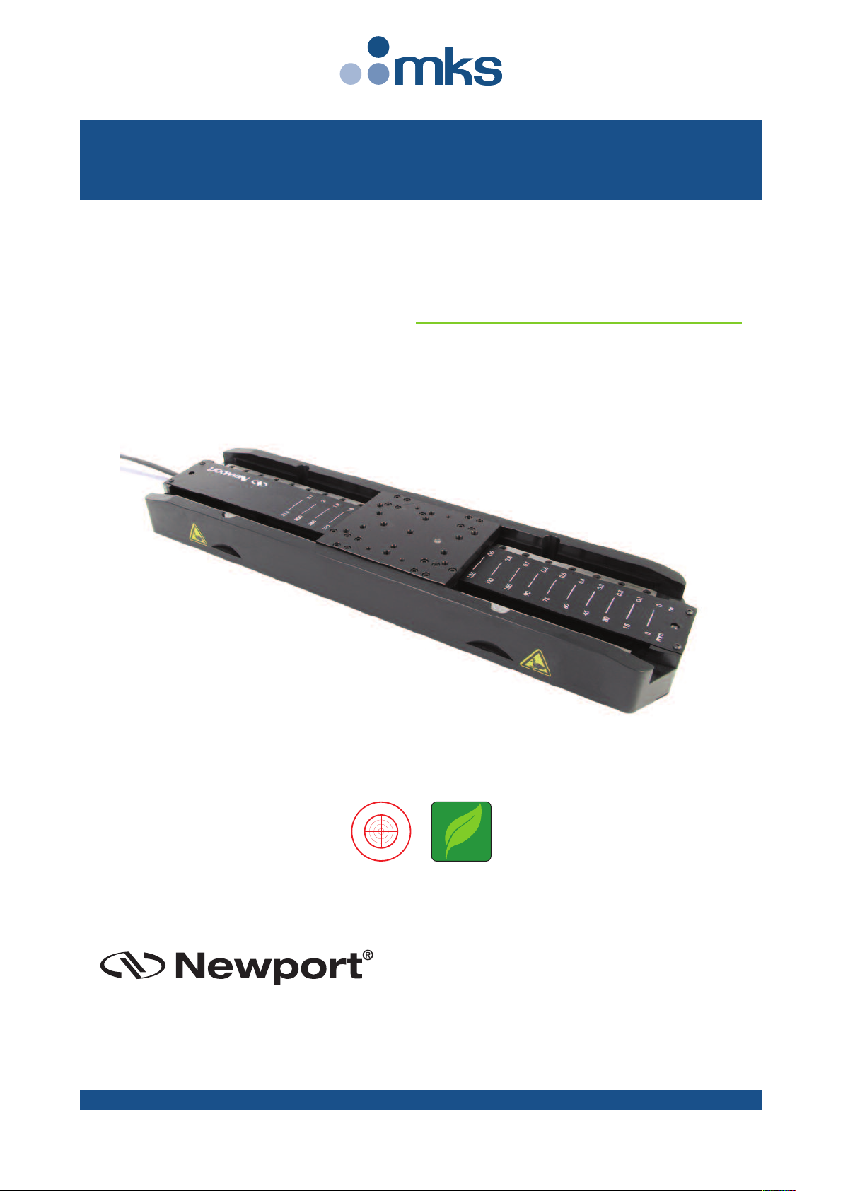
DL Stage Series
High-Performance
Delay Line Stages
USER’S MANUAL
Page 2
DL Stage Series High-Performance Delay Line Stages
Newport Corporation warrants this product to be free from defects in
material and workmanship for a period of 1 year from the date of
shipment. If found to be defective during the warranty period, the product
will either be repaired or replaced at Newport’s discretion.
To exercise this warranty, write or call your local Newport representative,
or contact Newport headquarters in Irvine, California. You will be given
prompt assistance and return instructions. Send the instrument,
transportation prepaid, to the indicated service facility. Repairs will be
made and the instrument returned, transportation prepaid. Repaired
products are warranted for the balance of the original warranty period, or
at least 90 days.
Limitation of Warranty
This warranty does not apply to defects resulting from modification or
misuse of any product or part.
This warranty is in lieu of all other warranties, expressed or implied,
including any implied warranty of merchantability or fitness for a
particular use. Newport Corporation shall not be liable for any indirect,
special, or consequential damages.
by Newport Corporation, Irvine, CA. All rights reserved.
Original instructions.
No part of this document may be reproduced or copied without the prior
written approval of Newport Corporation. This document is provided for
information o nl y, and pro du ct specifications are subject to change without
notice. Any change will be reflected in future publishings.
CAUTION
Warranty does not apply to damages resulting from:
• Incorrect usage:
– Load on the stage greater than maximum specified load.
– Carriage speed higher than specified speed.
–Improper grounding.
¬ Connectors must be properly secured.
¬ When the load on the stage represents an electrical risk, it must
be connected to ground.
– Excessive or improper cantilever loads.
• Modification of the stage or any part thereof.
CAUTION
Please return equipment in
the original (or equivalent)
packing.
You will be responsible for
damage incurred from
inadequate packaging if the
original packaging is not
used.
Warranty
EDH0391En1031 — 03/18 ii
© 2018
Page 3

DL Stage Series High-Performance Delay Line Stages
Table of Contents
Warranty .................................................................................................................ii
EC Declaration of Conformity...............................................................................v
Definitions and Symbols.......................................................................................vi
Warnings ...............................................................................................................vii
Cautions .................................................................................................................ix
1.0 — Introduction.................................................................................1
1.1 Unpacking Instruction ..............................................................................1
2.0 — Description ...................................................................................2
2.1 Design Details ............................................................................................2
3.0 — Characteristics............................................................................3
3.1 Definitions ..................................................................................................3
3.2 Mechanical Specifications .......................................................................4
3.3 Stage Initialization.....................................................................................4
3.4 Static Load Characteristics and Stiffness ..............................................4
3.5 Dynamic Characteristics ..........................................................................5
Description of Parameters .......................................................................5
Stages Adjustement Proposal in Function of the Load .......................5
Payload Adjustment Influence on Displacement ..................................6
DL Stage Acceleration...............................................................................6
3.6 Stage Weights ............................................................................................7
4.0 — Motor & Feedback ....................................................................7
4.1 Brushless Motor Characteristics ............................................................7
4.2 Feedback Signal Position .........................................................................7
4.3 Pinouts........................................................................................................8
Motor Connector (SUB-D25M).................................................................8
Encoder Connector (HD26M) ..................................................................8
5.0 — Connection to Newport Controllers ................................9
5.1 Warnings on Controllers ..........................................................................9
5.2 Connection ...............................................................................................10
Newport cables .......................................................................................10
6.0 — Connection to Non-Newport Electronics ....................11
6.1 Connections .............................................................................................11
7.0 — Dimensions.................................................................................12
iii EDH0391En1031 — 03/18
Page 4

DL Stage Series High-Performance Delay Line Stages
8.0 — Optical Kits.................................................................................13
8.1 DL-BKIT19 Kit...........................................................................................13
8.2 DL-BKIT1U Kits ........................................................................................14
8.3 DL-BKIT2U Kits ........................................................................................14
8.4 DL-BKIT4U Kits ........................................................................................15
9.0 — Maintenance ..............................................................................16
9.1 Maintenance ............................................................................................16
9.2 Repair .......................................................................................................16
9.3 Calibration ...............................................................................................16
Service Form .........................................................................................................17
EDH0391En1031 — 03/18 iv
Page 5
DL Stage Series High-Performance Delay Line Stages
Delay Line Series
EU Declaration of Conformity
following Annex II-1A
of Directive 2006/42/EC on machinery
The manufacturer:
MICRO-CONTROLE Spectra-Physics,
9, rue du bois sauvage
F-91055 Evry FRANCE
Hereby declares that the machinery:
y Description: " DL "
y Function: High-Performance Delay Line Stages with Single-Axis Motion
Controller/Driver.
y Models: DL125/225/325.
– the technical file of which was compiled by:
Mr Hervé LE COINTE, Directeur Qualité,
MICRO-CONTROLE Spectra-Physics, Zone Industrielle - B.P.29
F-45340 Beaune La Rolande France
– complies with all the relevant provisions of the Directive 2006/42/EC on machinery.
– complies with all the relevant provisions of the Directive 2014/30/EU relating to electromagnetic compatibility.
– complies with all the relevant provisions of the Directive 2011/65/EU relating to RoHS2.
– was designed and built in accordance with the following harmonised standards:
y NF EN 61326-1:2013 « Electrical equipment for measurement, control and
laboratory use – EMC requirements – Part 1: General requirements »
y NF EN 55011:2010/A1:2011 Class A
– was designed and built in accordance with the following other standards:
y NF EN 61000-4-2
y NF EN 61000-4-3
y NF EN 61000-4-4
y NF EN 61000-4-5
ORIGINAL DECLARATION
Done in Beaune La Rolande on 16 May 2017
Hervé LE COINTE
Quality Director
DC1-EN rev:A
y NF EN 61000-4-6
y NF EN 61000-4-8
y NF EN 61000-4-8
y NF EN 61000-4-11
EC Declaration of Conformity
v EDH0391En1031 — 03/18
Page 6
DL Stage Series High-Performance Delay Line Stages
The following terms and symbols are used in this documentation and also
appear on the product where safety-related issues occur.
General Warning or Caution
The exclamation symbol may appear in warning and caution tables in this
document. This symbol designates an area where personal injury or
damage to the equipment is possible.
The following are definitions of the Warnings, Cautions and Notes that may
be used in this manual to call attention to important information regarding
personal safety, safety and preservation of the equipment, or important
tips.
WA RN IN G
Warning indicates a potentially dangerous situation which can result in
bodily harm or death.
CAUTION
Caution indicates a potentially hazardous situation which can result in
damage to product or equipment.
NOTE
Note indicates additional information that must be considered by the
user or operator.
European Union CE Mark
The presence of the CE Mark on Newport Corporation equipment means
that it has been designed, tested and certified as complying with all
applicable European Union (CE) regulations and recommendations.
Warnings and Cautions
ATTENTIO N
This stage is a Class A device. In a residential environment, this device
can cause electromagnetic interference. In this case, suitable measures
must be taken by the user.
Definitions and Symbols
EDH0391En1031 — 03/18 vi
Page 7
DL Stage Series High-Performance Delay Line Stages
W
ARNING
The motion of objects of all types carries potential risks for operators.
Ensure the protection of operators by prohibiting access to the dangerous
area and by informing the personnel of the potential risks involved.
WA RN IN G
The magnetic channel included in this device has the potential to disrupt
pacemakers. Consequently, it is recommended that individuals maintain a
distance of 1 meter or more from the stage as a precautionary measure.
WA RN IN G
Do not use this stage when its motor is emitting smoke or is unusually
hot to the touch or is emitting any unusual odor or noise or is in any
other abnormal state.
Stop using the stage immediately, switch off the motor power and then
disconnect the electronics power supply.
After checking that smoke is no longer being emitted contact your
Newport service facility and request repairs. Never attempt to repair the
stage yourself as this can be dangerous.
WA RN IN G
Make sure that this stage is not exposed to moisture and that liquid does
not get into the stage.
Nevertheless, if any liquid has entered the stage, switch off the motor
power and then disconnect the electronics from power supply.
Contact your Newport service facility and request repairs.
WA RN IN G
Do not insert or drop objects into this stage, this may cause an electric
shock, or lock the drive.
Do not use this stage if any foreign objects have entered the stage.
Switch off the motor power and then disconnect the electronics power
supply.
Contact your Newport service facility for repairs.
WA RN IN G
Do not place this stage in unstable locations such as on a wobbly table or
sloping surface, where it may fall or tip over and cause injury.
If this stage has been dropped or the case has been damaged, switch off
the motor power and then disconnect the electronics power supply.
Contact your Newport service facility and request repairs.
Warnings
vii EDH0391En1031 — 03/18
Page 8
DL Stage Series High-Performance Delay Line Stages
WA RN IN G
Do not attempt to modify this stage; this may cause an electric shock or
downgrade its performance.
W
ARNING
Do not exceed the usable depth indicated on the mounting holes (see
section “Dimensions”). Longer screws can damage the mechanics or
cause a short-circuit.
WARNING
Do not exceed speed and load limitations as specified in this manual.
EDH0391En1031 — 03/18 viii
Page 9
DL Stage Series High-Performance Delay Line Stages
C
AUTION
Do not place this stage in a hostile environment such as X-Rays, hard
UV,… or in any vacuum environment.
CAUTION
Do not place this stage in a location affected by dust, oil fumes, steam or
high humidity. This may cause an electric shock.
CAUTION
Do not leave this stage in places subject to extremely high temperatures
or low temperatures. This may cause an electric shock.
• Operating temperature: +10 to +35 °C
• Storage/Operating altitude: 1000 m
• Storage/Operating humidity: 85%
• Storage temperature: -10 to +40 °C (in its original packaging)
CAUTION
Do not move this stage if its motor power is on.
Make sure that the cable to the electronics is disconnected before
moving the stage. Failure to do so may damage the cable and cause an
electrical shock.
CAUTION
Be careful that the stage is not bumped when it is being carried. This
may cause it to malfunction.
CAUTION
When handling this stage, always unplug the equipment from the power
source for safety.
CAUTION
When the carriage is in its end-of-run position, it is strongly recommended
not to go beyond this point as this may damage the stage mechanism.
CAUTION
Cautions
ix EDH0391En1031 — 03/18
Contact your Newport service facility to request cleaning and
specification measurement every year.
Page 10

DL Stage Series High-Performance Delay Line Stages
EDH0391En1031 — 03/18 x
Page 11

DL Stage Series High-Performance Delay Line Stages
High-Performance Delay Line Stages
DL Stage Series
1.0 —Introduction
This manual provides operating instructions for the stage that you have
purchased.
We recommend you read the chapter “Connection to electronics” before
using the DL stage.
1.1 Unpacking Instruction
DL325 Stage.
RECOMMENDATION
NOTE
Please unscrew the two knobs before removing the stage from the
plastic bag
1 EDH0391En1031 — 03/18
Page 12

DL Stage Series High-Performance Delay Line Stages
RoHS
Compliant
NOTE
This product complies with the RoHS directive
(Restriction of Hazardous Substances) .
2.0 —Description
The DL linear stages Series is a high performance but very affordable,
inear motor driven with an integrated motion controller. Optimized for
l
mall loads, repeatable positioning and fast traverse speeds, it’s an ideal
s
olution for spectroscopy applications ranging from pump-probe,
s
interferometry, 2DIR, etc.
With travel ranges of 125 mm, 225 mm and 325 mm, this offering covers
almost all possible delay needs from femtosecond to nanosecond delays.
The DL stage utilizes an FEM-optimized extruded aluminum body that is
extremely stiff, while minimizing the bending effect caused by the different
thermal expansion coefficients of the aluminum body and the steel rails.
The rails' position relative to the profile’s neutral fiber minimizes the effect
due to bi-metal thermal expansion. The body's rigidity minimizes the
deflection under load.
The stage has been designed to be mounted on standard breadboards
(with a 0.2 mm flatness). This minimizes the effect of the table to pitch,
yaw and roll performance of the stage.
Recirculating ball bearing slides provide excellent payload capabilities and
long life. The movement is smooth with low noise.
Unlike screw driven stages, the DL employs a centered, high efficiency 3phase, synchronous ironless, linear motor as the driving element. This
drive system is absolutely non-contact, and has the advantage of higher
speed, high acceleration and high system responsiveness without wear
associated with motor brushes or drive screws. And because of the fully
integrated linear motor, the DL is shorter than a comparable screw driven
stage.
Precision position feedback is provided by a very repeatable linear scale
mounted in the stage. The encoder signals are interpolated by the
dedicated Newport motion controller with nanometer resolution for
outstanding position sensitivity, repeatability, and stability. A home
position is incorporated on the same scale, avoiding the use of additional
electronics or mechanics for improved reliability and accuracy.
Thus, the DL is the optimum solution for space constrained applications
that require high-throughput, high reliability, and ultra-quiet operation.
To facilitate setups, beam kits consisting of retroreflectors, mirrors,
mounts and other optomechanical parts, are available to suit various
wavelengths and delay line configurations.
2.1 Design Details
EDH0391En1031 — 03/18 2
Base Material Extruded Aluminum
Bearings Recirculating bearings
Drive System 3-phase synchronous ironless linear motor (without Hall effect sensors)
Motor Initialization Has to be done by the controller
Motor Commutation Done by the controller on encoder feedback
Feedback Linear glass scale, 80 µm signal period, 1 V
Limit Optical
Home Switch Optical, on encoder’s fiducial track, located at the minus end of travel
Controller Compatibility DL Controller
Cable 3 m long pigtail cables included
MTBF 20,000 hours
PP
Page 13

DL Stage Series High-Performance Delay Line Stages
Specifications of our products are established in reference to ISO 230
standard part II “Determination of accuracy and repeatability of
positioning numerically controlled axes”.
T
his standard gives the definition of position uncertainty which depends
on the 3 following parameters:
Absolute Accuracy
Difference between ideal position and real position.
Accuracy
Difference between ideal position and real position after the compensation
of linear errors.
Linear errors include: cosine errors, inaccuracy of screw or linear scale
pitch, angular deviation at the measuring point (Abbe error) and thermal
expansion effects. All Newport motion electronics can compensate for
linear errors.
The relation between absolute accuracy and on-axis accuracy is as follows:
Absolute Accuracy = On-Axis Accuracy + Correction Factor
x Travel
Repeatability
Ability of a system to achieve a commanded position over many attempts.
Reversal Value (Hysteresis)
Difference between actual position values obtained for a given target
position when approached from opposite directions.
Minimum Incremental Motion (MIM)
The smallest increment of motion a device is capable of delivering
consistently and reliably.
Resolution
The smallest increment that a motion device can theoretically move
and/or detect. Resolution is not achievable, whereas MIM, is the real
output of a motion system.
Yaw, Pi tch
Rotation of carriage around the Z axis (Yaw) or Y axis (Pitch), when it
moves.
The testing of accuracy, repeatability, and reversal error are made
systematically with test equipment in controlled environment (20±1°C).
A linear cycle with 21 data points on the travel and 4 cycles in each
direction gives a total of 164 points.
Guaranteed Specifications
Guaranteed maximum performance values are verified per Newport's A167
metrology test procedure. For more information, please consult the
metrology tutorial section in the Newport catalog or at www.newport.com
3.0 —Characteristics
3.1 Definitions
3 EDH0391En1031 — 03/18
Page 14

DL Stage Series High-Performance Delay Line Stages
G
U
A
R
A
N
T
E
E
D
S
P
E
C
I
F
I
C
A
T
I
O
N
S
Z
Y
C
z
X
k
α
z
k
α
x
kα
y
3.2 Mechanical Specifications
DL125 DL225 DL325
Travel Range (mm) 125 225 325
Minimum Incremental Motion (nm) 75 75 75
Bi-directional Repeatability, Guaranteed
Accuracy, Guaranteed
(1) (2)
(µm) ±1.5 ±2 ±2.5
(1)
(µm) ±0.15 ±0.15 ±0.15
Encoder Resolution (nm) 50 50 50
Origin Repeatability (µm) 0.4 0.4 0.4
Maximum Speed
(3)
(mm/s) [See chapters 3.3 to 3.6] 500 500 500
Maximum Acceleration, No Load (mm/s2) [See chapters 3.3 to 3.6] 7500 7500 7500
Pitch, Typical (Guaranteed)
Yaw, Typical (Guaranteed)
(1) (2) (4)
(µrad) ±60 (±100) ±60 (±100) ±90 (±150)
(1) (2) (4)
(µrad) ±30 (±60) ±40 (±90) ±50 (±120)
Load Capacity (N) See chapter 3.4.3
1)
Shown are peak to peak, guaranteed specifications or ±half the value as sometimes shown. For the definition of
typical specifications which are about 2X better than the guaranteed values, visit www.newport.com for the
Motion Control Metrology Primer.
2)
For a travel of 325 mm.
)
3
With DL controller.
)
4
To obtain arcsec units, divide µrad value by 4.8.
CAUTION
To reach the specifications stated, stages must be fixed on a plane
surface with a flatness of 5 µm with washer under each fixing screw
head (max. tightening torque for mounting screws: 3 Nm).
3.3 Stage Initialization
CAUTION
Before initializing the stage, be sure that the carriage is not positionned
close to the end of run.
3.4 Static Load Characteristics and Stiffness
Normal Load Capacity (Cz)
Maximum load a stage can move while maintaining specifications.
Cz, Normal centered load capacity 200 N (see note)
Kax, Compliance in roll 15 µrad/Nm
Kay, Compliance in pitch 10 µrad/Nm
Kaz, Compliance in yaw 10 µrad/Nm
NOTE
For Delay line applications, the DL stage load capacity (on carriage) is
limited to 20 N. It is recommended to keep the load centered on the
EDH0391En1031 — 03/18 4
carriage.
Page 15

DL Stage Series High-Performance Delay Line Stages
3.5 Dynamic Characteristics
Dynamic response of the stage depends on two parameters:
• The force delivered by the motor
• The total moving mass including carriage mass and payload
Newport’s DL Controller includes four parameters allowing dynamic
control optimization of the stage:
• Scaling Force
• Force Limit
• Carriage Mass
• Payload Mass
Although the three parameters are set in the factory perstage, the fourth
(Payload Mass) must be adjusted by the user. Refer to the “FM” command
of the Newport DL Controller user’s manual.
3.5.1 Description of Parameters
The DL Controller/driver "ScalingForce" parameter is used by the
controller to scale the output current. It indicates the theoretical
maximum force (friction not taken in account) of the DL carriage with the
controller full scale current (See Controller Manual).
The DL Controller/driver "ForceLimit" parameter indicates the maximum
force of the DL stage carriage limited by current saturation to avoid stage
damage.
Then, stage carriage acceleration can be calculated using the following
formula:
MaxAccelaration =
Carriage Mass + Payload mass
ForceLimit - Friction Constant
See chapter 3.4.3 acceleration/Load graph.
• Due to its linear motor and rails, DL stage Friction Constant is only 4 N.
• Carriage Mass is 0.85 kg.
3.5.2 Stages Adjustement Proposal in Function of the Load
In order to improve and have better driving performances, it is advisable
to change the control parameters according to the load. All the stages are
delivered with a crossover frequency of 70 Hz. You can change the
parameters KP, KI, KD, FD, FL and FMP in the controller terminal. Please
see the following table:
Customer payload from
High (2 kg ) to low (0 kg)
FMP command
Response Time Slow Medium Fast
Crossover Frequency (Hz) 55 70 80
KP 19,000 31,000 48,000
KI 2,000,000 3,500,000 5,000,000
KD 350 420 500
Derivative cut off frequency (FD) 100 140 150
PID 2nd Order low pass filter (FI) 4,000 4,000 4,000
High Medium Low
5 EDH0391En1031 — 03/18
Page 16

DL Stage Series High-Performance Delay Line Stages
Centered Load (N)
0 2018161412108642
Acceleration (mm/s
2
)
0
8000
7000
6000
5000
4000
3000
2000
1000
Time
Payload mass too high vs adjustment Payload mass too low vs adjustment
t 2t0
0
-X
X
Displacement
Time
t 2t0
Payload mass good vs adjustment
Time
t 2t0
L
OAD
1 kg
FREQUENCY
O
F THE PAYLOAD
300 Hz
MOTION AFTER EXCITATION
DL STAGE
3.5.3 Payload Adjustment Influence on Displacement
CAUTION
L linear motor stages are sensitive to load variations and system
D
stiffness. The charts below show the behavior of the displacement an
underestimated/overestimated moving mass.
The driving force requires a good adjustment of the “Forces and Masses”
(FM) and the payload (FMP) parameters. Refer to the “FM” and “FMP”
commands in the DL Controller manual.
3.5.4 DL Stage Acceleration
Below is a chart illustrating the allowable operating area of the stage
based on the load.
Total load = Pay Load + Carriage Mass (0.85 kg)
EDH0391En1031 — 03/18 6
Page 17

DL Stage Series High-Performance Delay Line Stages
Direction +
Direction – Motion Direction +
1 V
2 V
Encoder
Cosine
1 V
2 V
Encoder
Cosine
1234
1 V
2 V
Encoder
Sine
1 V
2 V
Encoder
Sine
3.6 Stage Weights
The stage weight below does not include the cable.
Weight [lb (kg)]
DL125 7.1 (3.2)
DL225 8.8 (4.0)
DL325 10.4 (4.7)
4.0 —Motor & Feedback
Motor Magnet Nominal Max. RMS Max. Peak Resistance Inductance
Constant Pitch Voltage Current Current per Phase per Phase
(N2/W) (mm) (V) (A) (A) (Ω) (mH)
DL Stage 4.2 30 42 1.3 4.2 4 0.72
7 EDH0391En1031 — 03/18
4.1 Brushless Motor Characteristics
4.2 Feedback Signal Position
Page 18

DL Stage Series High-Performance Delay Line Stages
1
3
2
5
14
1
9
10
18
26
19
1
4.3 Pinouts
The connections for DL stages are given in the following tables:
4.3.1 Motor Connector (SUB-D25M)
1 U Motor
2 U Motor
3 N.C.
4 N.C.
5 V Motor
6 V Motor
7 W Motor
8 W Motor
9 Reserved (Thermistor)
10 N.C.
11 N.C.
12 N.C.
13 N.C.
4.3.2 Encoder Connector (HD26M)
1 +5 V
2 N.C.
3 N.C.
4 Cosine
5 - End-of-Run
6 Sine
7 Ground
8 Index Pulse I
9 N.C.
10 N.C.
11 N.C.
12 N.C.
13 /Cosine
14 Ground
15 N.C.
16 Ground
17 Reserved (SMDAT)
18 Reserved (SMCLK)
19 N.C.
20 N.C.
21 +5 V
22 Ground
23 N.C.
24 N.C.
25 N.C.
14 + End-of-Run
15 /Sine
16 N.C.
17 Index Pulse /I
18 N.C.
19 + 5 V
20 N.C.
21 N.C.
22 N.C.
23 N.C.
24 N.C.
25 Ground
26 Ground
EDH0391En1031 — 03/18 8
Page 19

DL Stage Series High-Performance Delay Line Stages
Controllers are intended for use by qualified personnel who recognize
shock hazards and are familiar with safety precautions required to avoid
p
ossible injury. Read the controller user’s manual carefully before
operating the instrument and pay attention to all written warnings and
cautions.
WA RN IN G
Disconnect the power plug under the following circumstances:
• If the power cord or any attached cables are frayed or damaged in
any way.
• If the power plug is damaged in any way.
• If the unit is exposed to rain, excessive moisture, or liquids are spilled
on the unit.
• If the unit has been dropped or the case is damaged.
• If you suspect service or repair is required.
• Whenever you clean the electronics unit.
CAUTION
To protect the unit from damage, be sure to:
• Keep all air vents free of dir t and dust.
• Keep all liquids away from the unit.
• Do not expose the unit to excessive moisture (85% humidity).
• Read this manual before using the unit for the first time.
WA RN IN G
All attachment plug receptacles in the vicinity of this unit are to be of
the grounding type and properly polarized.
Contact your electrician to check your receptacles.
WA RN IN G
This product is equipped with a 3-wire grounding type plug.
Any interruption of the grounding connection can create an electric
shock hazard.
If you are unable to insert the plug into your wall plug receptacle,
contact your electrician to perform the necessary alterations to ensure
that the green (green-yellow) wire is attached to ear th ground.
WA RN IN G
This product operates with voltages that can be lethal.
Pushing objects of any kind into cabinet slots or holes, or spilling any
liquid on the product, may touch hazardous voltage points or short out
parts.
5.0 —Connection to Newport Controllers
5.1 Warnings on Controllers
9 EDH0391En1031 — 03/18
Page 20

DL Stage Series High-Performance Delay Line Stages
5.2 Connection
On each stage is represented a label which indicates its name and its serial
umber.
n
WARNING
Always turn the controller's power OFF before connecting to a stage.
Stages may be connected to the rear panel motor connectors any time
prior to power-up with the supplied cable assemblies.
NOTE
These stages are equipped with a chipset memorizing parameters.
Newport's exclusive technology enables Newport DL Controllers to
recognize the connected Newport stage. This ensures that the user can
operate the motion system quickly and safely.
5.2.1 Newport cables
DL stages are delivered with two 3-meter pigtailed cables that can be
directly connected to Newport Controllers.
DL Series stages can only operate with cable lengths of 3 m max.
These cables are shielded. For correct operation, make sure to lock
connectors (ground continuity provided by cables).
Keep the cables at a safe distance from other electrical cables in your
environment to avoid potential cross talk.
WARNING
WARNING
WARNING
EDH0391En1031 — 03/18 10
Page 21

DL Stage Series High-Performance Delay Line Stages
S
UB-D25M
C
onnector
1
& 2
5
& 6
7 & 8
17
18
21
9
22
14 & 16
Connector
Cap
C
onnection
D
LS
U
Motor
V
Motor
W Motor
SMDAT
SMCLK
+5 V
Ground
Ground
Ground
Connector
Cap
Sub-HD26M
Connector
4
13
6
15
8
17
1 & 19
14
5
7, 25 & 26
Connector
Cap
Connection
DLS
Encoder Cosine
Encoder /Cosine
Encoder Sine
Encoder /Sine
Index Pulse I
Index Pulse /I
+5 V
+ End-of-Run
- End-of-Run
Ground
Connector
Cap
MOTOR ENCODER
6.0 —Connection to Non-Newport Electronics
6.1 Connections
WARNING
ewport is not responsible for malfunction or damage to a DL stage
N
when it is used with non-Newport controllers.
WARNING
Newport guarantees
“”compliance of the DL stages only if they are
used with Newport cables and controllers.
Nevertheless, the figure below shows the wiring when an DL stage is
used with non-Newport controllers.
11 EDH0391En1031 — 03/18
Page 22

DL Stage Series High-Performance Delay Line Stages
4.58 (115)
L
C
A
1
.97
(
50)
B
MODEL TRAVEL L A
B C
DL125
4.92 11.42 5.91 6.0 5.91
(125) (290) (150) (152.4) (150)
DL225
8.86 15.35 7.87 8.0 7.87
(225) (390) (200) (203,2) (200)
DL325
12.80 19.29 9.84 10.0 9.84
(325) (490) (250) (254) (250)
1.75
(44.45)
3.96
(100.6)
4.88
(124)
4 CLEARANCE HOLES
FOR 1/4-20 OR M6 SCREWS
4 HOLES M6 THD, DEPTH: .28 (7)
ON 2.95 x .98 (75 x 25)
4 HOLES M6 THD, DEPTH: .28 (7)
ON 3.54 x 1.97 (90 x 50)
4 HOLES M4 THD, DEPTH: .31 (8)
ON 1.18
x 2.95 (30 x 75)
5 HOLES M6 THD,
DEPTH: .28 (7)
MODEL SHOWN: DL325
DIMENSIONS IN INCHES (AND MILLIMETERS)
USE THESE 2 LINES TO PLACE
THE NEWPORT MIRROR MOUNTS
7.0 —Dimensions
EDH0391En1031 — 03/18 12
NOTE
The DL Stage can be clamped with
Newport BC-5 or BC-6.
Page 23

DL Stage Series High-Performance Delay Line Stages
2
1
4
5
3
USE THESE 2 LINES TO PLACE
THE 9848 MIRROR MOUNT
8.0 —Optical Kits
Four optical assemblies have been specially designed to be mounted on
L Stages to faciliate setting up a delay line.
D
Stage Single Pass Dual pass Quad Pass
DL125 0.8 1.7 3.3
Delay (ns) DL125 1.5 3 6
DL325 2.2 4.3 8.7
MIM (fs) 0.5 1 2
8.1 DL-BKIT19 Kit
One-pass, beam height of 3 inches.
DL-BKIT19 for InfraRed, Visible light and Ultraviolet.
Total mass on carriage (Payload): 0.4 kg.
The DL-BKIT19 kit includes the following components:
• To be mounted on the breadboard:
1 & 2: 2 sets of: U100 + M-PS-2 + M-PS-F
3: ID-0.5 + MH-2P + M-PS-2 + M-PS-0.125 + PS 0.25 + PS-F
• To be mounted on the carriage:
4: 9848 + M-SS-1-B
5: ID-0.5 + MH-2P + M-PS-2 + M-PS-0.5 + M-PS-0.125 + PS-F
13 EDH0391En1031 — 03/18
Page 24

DL Stage Series High-Performance Delay Line Stages
2
1
4
3
2
1
3
5
4
8.2 DL-BKIT1U Kits
One-pass, beam height of 3.5 inches.
DL-BKIT1U-S for InfraRed and Visible light.
L-BKIT1U-UV for Ultraviolet.
D
Total mass on carriage (Payload): 0.85 kg.
The DL-BKIT1U kits include the following components:
• To be mounted on the breadboard:
1 & 2: 2 sets of: U100 + M-PS-2 + M-PS-0.5E + PS-F
3: ID-0.5 + MH-2P + M-PS-2 + M-PS-0.5E + PS 0.125 + PS-0.25+ PS-F
• To be mounted on the carriage:
4: M-360-90 + UBBR2.5
8.3 DL-BKIT2U Kits
Two-pass, beam height of 3.5 inches.
DL-BKIT2U-S for InfraRed and Visible light.
DL-BKIT2U-UV for Ultraviolet.
Total mass on carriage (Payload): 0.85 kg.
The DL-BKIT2U kits include the following components:
• To be mounted on the breadboard:
1: 9848KT + M-PS-1E + M-PS-0.5 + PS-F
2 & 3: 2 sets of: U100 + M-PS-0.5E + M-PS-2E+ PS-F
4: ID-0.5 + MH-2P + M-PS-0.5 + M-PS-2E + PS 0.125 + PS-0.25+ PS-F
• To be mounted on the carriage:
5: M-360-90 + UBBR2.5
EDH0391En1031 — 03/18 14
Page 25

5
3
1
2
6
4
DL Stage Series High-Performance Delay Line Stages
8.4 DL-BKIT4U Kits
Four-pass, beam height of 3.5 inches.
DL-BKIT4U-S for InfraRed and Visible light.
L-BKIT4U-UV for Ultraviolet.
D
Total mass on carriage (Payload): 1.4 kg.
The DL-BKIT4U kits include the following components:
• To be mounted on the breadboard:
1 & 2: 2 sets of: 9848KT + M-PS-0.5 + M-PS-1E + PS-F
(1 set with elliptical mirrors)
3 & 4: 2 sets of: U100 + M-PS-0.5 + M-PS-2E + PS-F
5: ID-0.5 + MH-2P + M-PS- 0.5 + M-PS-2E + M-PS-0.125 + M-PS-0.25
+ PS-F
• To be mounted on the carriage:
6: M-360-90 + 2 pieces of UBBR2.5
15 EDH0391En1031 — 03/18
Page 26

DL Stage Series High-Performance Delay Line Stages
9.0 —Maintenance
ECOMMENDATION
R
It is recommended to contact our After Sales Service who can assist you
with the appropriate maintenance for your application.
9.1 Maintenance
The DL stage requires no particular maintenance. Nevertheless, this is a
precision mechanical device that must be kept and operated in good
condition.
PRECAUTIONS
The DL stage must be used or stocked in a clean environment, without
dust, humidity, solvents or other substances.
It is recommended to return your DL stage to Newport's Service Team
after every 2000 hours of use for lubrication and cleaning.
If your stage is mounted on a workstation and cannot be easily
removed, please contact Newport's Service for further instructions.
9.2 Repair
Never attempt to disassemble a component of the stage that has not
been covered in this manual.
To disassemble a non specified component can cause a malfunction of
the stage.
If you observe a malfunction in your stage, please contact us immediately
to arrange for a repair.
Any attempt to disassemble or repair a stage without prior
authorization will void your warranty.
RECOMMENDATION
CAUTION
CAUTION
9.3 Calibration
It is recommended to return your DL stage to Newport once a year for
recalibration to its original specifications.
EDH0391En1031 — 03/18 16
CAUTION
Page 27

Your Lo ca l R ep re se nt at iv e
Tel. :
F
ax:
N
ame:
Company:
Address:
Country:
P. O . N u m b e r :
Item(s) Being Returned:
Model #:
Description:
Reasons of return of goods (please list any specific problems):
R
eturn authorization #:
(Please obtain prior to return of item)
Date:
Phone Number:
Fax Number:
Serial #:
Service Form
17 EDH0391En1031 — 03/18
Page 28

Visit Newport Online at:
North America & Asia
Newport Corporation
1791 Deere Ave.
Irvine, CA 92606, USA
Sales
Tel.: (800) 222-6440
e-mail: sales@newport.com
Technical Support
Tel.: (800) 222-6440
e-mail: tech@newport.com
Service, RMAs & Returns
Tel.: (800) 222-6440
e-mail: service@newport.com
Europe
MICRO-CONTROLE Spectra-Physics S.A.S
9, rue du Bois Sauvage
91055 Évry CEDEX
France
Sales & Technical Support
Tel.: +33 (0)1.60.91.68.68
e-mail: france@newport.com
Service & Returns
Tel.: +33 (0)2.38.40.51.55
www.newport.com
 Loading...