

Page 1
90088262 MCS130B, Rev B
s
1/8m Monochromator Family
User's Manual
Cornerstone
™
130B
Page 2

90088262 MCS130B
CORNERSTONE 130B MONOCHROMATORS
2
TABLE OF CONTENTS
1 GENERAL INFORMATION .................................................................................................. 5
1.1 SYMBOLS AND DEFINITIONS ................................................................................ 6
1.2 GENERAL WARNINGS .......................................................................................... 7
1.3 ELECTRICAL HAZARDS ........................................................................................ 7
1.4 MECHANICAL HANDLING ................................ ...................................................... 8
1.5 OPTICS CARE AND HANDLING.............................................................................. 8
2 INTRODUCTION................................................................................................ ................ 9
2.1 OPTICAL CONFIGURATION ................................................................ ................... 9
2.2 STRAY LIGHT REJECTION ...................................................................................10
2.3 AVAILABLE MODELS ...........................................................................................10
2.4 TYPICAL APPLICATIONS......................................................................................11
3 INITIAL SETUP.................................................................................................................12
3.1 WHAT’S INCLUDED..............................................................................................12
3.2 UNPACKING ................................................................ ........................................12
3.3 CHOOSING A LOCATION......................................................................................12
3.4 MOUNTING OPTIONS ..........................................................................................13
3.5 ELECTRICAL AND COMPUTER CONNECTIONS .....................................................14
4 SHUTTER ................................................................................................ ........................16
5 INPUT AND OUTPUT SLITS...............................................................................................17
5.1 FIXED SLITS........................................................................................................17
5.2 MICROMETER ADJUSTABLE SLITS ......................................................................18
6 DIFFRACTION GRATINGS ................................................................................................20
6.1 GRATING TYPES .................................................................................................21
6.2 GRATING EFFICIENCY AND BLAZING ...................................................................22
6.3 POLARIZATION EFFECTS ....................................................................................24
7 MONOCHROMATOR RESOLUTION ................................................................................... 25
7.1 DETERMINING RESOLUTION ...............................................................................26
8 GETTING LIGHT INTO A MONOCHROMATOR ....................................................................28
8.1 ACCEPTANCE PYRAMID ......................................................................................28
8.2 F NUMBER MATCHING.........................................................................................29
9 BLOCKING HIGHER ORDER RADIATION ...........................................................................30
9.1 ORDER SORTING FILTERS ..................................................................................30
10 COMMUNICATION METHODS ...........................................................................................31
10.1 UTILITY SOFTWARE ............................................................................................33
10.2 HAND CONTROLLER ...........................................................................................34
10.3 TRACQ BASIC SOFTWARE...................................................................................35
10.4 LOW-LEVEL COMMANDS .....................................................................................35
11 GRATING INSTALLATION AND CALIBRATION ....................................................................36
11.1 RECALIBRATION SERVICES................................................................ .................36
11.2 SETTING THE WAVELENGTH OFFSET ................................................................ ..36
11.3 DETERMINING THE GRATING CALIBRATION FACTOR ...........................................37
11.4 ALTERNATIVE METHOD (CS130B only) .................................................................37
11.5 GRATING INSTALLATION ................................ .....................................................38
12 TROUBLESHOOTING ................................................................................................ .......40
12.1 CORRUPTED MEMORY........................................................................................40
13 SPECIFICATIONS.............................................................................................................41
14 DIMENSIONS ................................................................ ...................................................42
15 APPENDIX I: LOW LEVEL (REMOTE) COMMANDS AND QUERIES .......................................45
15.1 OPENING RS-232 COMMUNICATION INTERFACE ..................................................65
15.2 COMMAND AND QUERY SYNTAX .........................................................................65
15.3 STANDARD MODE ...............................................................................................65
Page 3

90088262 MCS130B
CORNERSTONE 130B MONOCHROMATORS
3
15.4 HANDSHAKE MODE.............................................................................................65
15.5 CS130B COMMAND REFERENCE SUMMARY ........................................................65
15.6 DETAILED COMMAND REFERENCE......................................................................65
15.7 ERROR CODES ...................................................................................................65
16 APPENDIX II: HAND CONTROLLER COMMANDS ...............................................................65
16.1 ACTIVATING THE HAND CONTROLLER.................................................................65
16.2 USING THE KEYPAD ................................................................ ............................65
16.3 KEY REFERENCE ................................................................................................66
17 APPENDIX IV: GRATING PHYSICS TUTORIAL ...................................................................68
17.1 THE GRATING EQUATION ....................................................................................68
17.2 THE GRATING EQUATION IN PRACTICE ...............................................................69
17.3 GRATING ORDER ................................................................................................70
17.4 GRATING DISPERSION ................................ ........................................................71
17.5 GRATING ILLUMINATION AND RESOLUTION.........................................................71
18 WARRANTY AND SERVICE...............................................................................................72
18.1 CONTACTING NEWPORT CORPORATION.............................................................72
18.2 REQUEST FOR ASSISTANCE / SERVICE ............................................................... 73
18.3 REPAIR SERVICE ................................................................ ................................73
18.4 NON-WARRANTY REPAIR ................................................................ ....................73
18.5 WARRANTY REPAIR ............................................................................................ 74
18.6 LOANER / DEMO MATERIAL ................................................................................. 75
Page 4

90088262 MCS130B
CORNERSTONE 130B MONOCHROMATORS
4
LIST OF FIGURES
Figure 1: Optical Configuration of the Cornerstone 130B ................................ ................................. 9
Figure 2: Model Number Codes................................................................................................ ..10
Figure 3: Tunable Monochromatic Light Source ................................ ............................................11
Figure 4: Monochromator with Lock-In Digital Amplifier ..................................................................11
Figure 5: Model 74017 Mounting Kit............................................................................................13
Figure 6: Monochromator Connections ........................................................................................15
Figure 7: A Fixed Slit Installed into the Holder...............................................................................17
Figure 8: Available Fixed Slits Table ...........................................................................................17
Figure 9: A Micrometer Adjustable Slit ......................................................................................... 18
Figure 10: A Fully Closed Micrometer Adjustable Slit .....................................................................18
Figure 11: Shortest Micrometer Adjustable Slit Height....................................................................19
Figure 12: Tallest Micrometer Adjustable Slit Height ......................................................................19
Figure 13: Grating Installed onto Mount .......................................................................................20
Figure 14: Grating Properties Table ............................................................................................21
Figure 15: Grating Efficiency Curves for CS130B Monochromator Pre-Configured Models ..................23
Figure 16: Resolution vs. Throughput ................................................................ ..........................25
Figure 17: Some of the Fixed Slit Sizes Available..........................................................................27
Figure 18: Acceptance Pyramid of Monochromator .......................................................................28
Figure 19: Grating Correctly “Filled” with Light ..............................................................................28
Figure 20: Mismatched F Numbers Resulting in Stray Light ............................................................ 29
Figure 21: F Number Matcher Used with Fiber Optic Cable ............................................................29
Figure 22: Model USFW-100 Filter Wheel ....................................................................................31
Figure 23: Model 74010 Filter Wheel...........................................................................................32
Figure 24: Mono Utility Software Screens ....................................................................................33
Figure 25: Cornerstone 130B Monochromator with 74009 Hand Controller .......................................34
Figure 26: TracQ Basic Screens .................................................................................................35
Figure 27: Grating Platform without Gratings ................................................................................39
Figure 28: Grating Platform with Gratings Installed ........................................................................39
Figure 29: Entering Calibration Values in Utility Software ...............................................................40
Figure 30: Cornerstone 130B Dimensions ....................................................................................42
Figure 31: 74001 Micrometer Adjustable Slit Dimensions ...............................................................43
Figure 32: 77294 Fixed Slit Dimensions.......................................................................................43
Figure 33: Model 74006 Mounting Plate.......................................................................................44
Figure 34: 74009 Hand Controller Keypad ...................................................................................65
Figure 35: The Sawtooth Pattern of a Grating Section....................................................................68
Figure 36: The Grating Equation Satisfied for a Parallel Beam of Monochromatic Light .......................69
Figure 37: Polychromatic Light Diffracted From a Grating ...............................................................69
Figure 38: Sign Convention for the Angle of Incidence, Angle of Diffraction and Grating Angle .............70
Page 5

90088262 MCS130B
CORNERSTONE 130B MONOCHROMATORS
5
1 0BGENERAL INFORMATION
Thank you for your purchase of this Cornerstone™ 130B Monochromator from Newport-Oriel
Instruments®.
Please carefully read the following important safety precautions prior to unpacking and operating this
equipment. In addition, please refer to the complete User’s Manual and all other documentation provided
for additional important notes and cautionary statements regarding the use and operation of the system.
Do not attempt to operate any system without reading all the information provided with each of the
components.
Please read all instructions that were provided prior to operation of the system. If
there are any questions, please contact Newport Corp. or the representative
through whom the system was purchased.
Page 6

90088262 MCS130B
CORNERSTONE 130B MONOCHROMATORS
6
1.1 18BSYMBOLS AND DEFINITIONS
WARNING
Situation has the potential to cause bodily harm or death.
CAUTION
Situation has the potential to cause damage to property or equipment.
ELECTRICAL SHOCK
Hazard arising from dangerous voltage. Any mishandling could result
in irreparable damage to the equipment, and personal injury or death.
EUROPEAN UNION CE MARK
The presence of the CE Mark on Newport Corporation equipment
means that it has been designed, tested and certified as complying
with all applicable European Union (CE) regulations and
recommendations.
WEEE
This symbol on the product or on its packaging indicates that this
product must not be disposed of with regular waste. Instead, it is the
user’s responsibility to dispose of waste equipment according t o the
local laws. The separate collection and recycling of the waste
equipment at the time of disposal will help to conserve natural
resources and ensure that the materials are recycled in a manner that
protects human health and the environment.
ON
The ON symbol in the above figure indicates the ON position of the
power switch.
OFF
The OFF symbol in the above figure indicates the OFF position of the
power switch.
Page 7

90088262 MCS130B
CORNERSTONE 130B MONOCHROMATORS
7
1.2 19BGENERAL WARNINGS
• Read all warnings and operating instructions for this system prior to setup and use.
• Do not use this equipment in or near water.
• To prevent damage to the equipment, read the instructions in the equipment manual for proper
input voltage and check the requirement on the power supply.
• This equipment is grounded through the grounding conductor of the power cord.
• Route power cords and other cables so they are not likely to be damaged.
• Disconnect power before cleaning the equipment
• Do not use liquid or aerosol cleaners; use only a damp lint-free cloth.
• Lock out all electrical power sources before servicing the equipment.
• To avoid explosion, do not operate this equipment in an explosive atmosphere.
• Qualified service personnel should perform safety checks after any service.
• If this equipment is used in a manner not specified in this manual, the protection provided by this
equipment may be impaired.
• Do not position this product in such a manner that would make it difficult to disconnect the power
cords.
• Use only the specified replacement parts.
• Follow precautions for static sensitive devices when handling this equipment.
• This product should only be powered as described in the manual.
• Do not remove the cover for normal usage.
1.3 20BELECTRICAL HAZARDS
Make all connections to or from the instrument with the power off.
The Cornerstone B requires DC voltage for operation, which is provided by an external power
supply. This power supply has no user serviceable parts. Do not attempt to open the external
power supply. Do not attempt to work in the Cornerstone B compartment without first
disconnecting the power cord, since electrical hazards are present inside the compartment even
with the power switch in the “off” position.
The Cornerstone B monochromator contains a microprocessor and should be installed with
appropriate surge/EMI/RFI protection on the power line. A dedicated power line or line isolation
may be required for some extremely noisy sites. The electronic circuits within the monochromator
are extremely sensitive to static electricity and radiated electromagnetic fields. Operation of this
instrument close to intense pulsed sources (lasers, xenon strobes, arc lamps, etc.) may
compromise performance if shielding is inadequate, and may cause permanent damage to the
microprocessor.
Note: This instrument conforms to CE standards for both safety and EMC. During normal use, this
equipment will not pose any electrical hazards to the user. Read all warnings before installing or
operating this system. If there are any questions or concerns, contact Oriel Instruments or the
regional sales representative for Newport.
Page 8

90088262 MCS130B
CORNERSTONE 130B MONOCHROMATORS
8
1.4 21BMECHANICAL HANDLING
Avoid dropping, sudden shocks, or rough handling of the monochromator since this may cause the
system to go out of calibration and may destroy the high precision drive components or optics.
1.5 22BOPTICS CARE AND HANDLING
Do not touch any optical surfaces since this is likely to cause irreparable damage. Always wear
powder-free gloves to cover the entire hand, not finger cots. Never touch the surface of a
diffraction grating, even when wearing gloves.
Dust or debris on the grating surface may negatively affect performance, so it should be prevented
from entering the instrument by keeping the protective grating covers in place when it is not in use.
If the gratings do require cleaning, do not attempt to clean any optical surface except by blowing
off dust or lint particles with a stream of dry clean air or nitrogen. Wiping the grating surface will
cause permanent damage.
Avoid getting any moisture or condensation onto the grating. Do not breathe on or talk directly in
front of a grating, as the moisture from one’s breath should never be allowed to condens e on t he
grating surface.
This instrument comes with gratings pre-installed, aligned, and the calibration parameters set. An
experienced user may choose to install a different grating in the field, although it is strongly
encouraged to send the instrument back to the factory instead.
If a grating is installed in the field, the grating cover must never touch the grating’s front surfac e.
The specially designed grating cover contacts only the edges of the grating. When removing this
cover, a grating can be scratched easily, so use extreme caution when handling.
Hand tighten the grating mount screws. Do not use tools, since this may cause damage to the
drive assembly. Never touch the surface of the grating, even while wearing gloves. Handle the
grating assembly only by its mount.
Page 9
90088262 MCS130B
CORNERSTONE 130B MONOCHROMATORS
9
2 1BINTRODUCTION
In developing the Cornerstone 130B monochromator, Newport-Oriel Instruments leveraged their
extensive experience to design a compact, inexpensive instrument that has all the versatility required by
researchers. The ease of automated control and small size also make this an ideal monochromator for
many OEM applications.
Each of these instruments includes two diffraction gratings, filter wheel control circuitry, and an integrated
electronic shutter. Communication may be established using USB, RS232, or an optional hand controller
designed specifically for use with the Cornerstone family of monochromators. In addition, this instrument
can be purged with dry nitrogen for work below the oxygen absorption cut-on at 180 nm.
The Cornerstone 130B includes a utility program designed to run on a computer using the Microsoft
Windows operating system. The simple, intuitive interface means that users can get up and running
within minutes of opening the box. Instrument control examples using National Instruments LabVIEW are
provided, along with a command set and API for those wishing to develop their own programs. An
optional hand controller may be used for quick access to all common commands and queries, without
requiring a computer. This is especially beneficial in universities and secure facilities.
A wide selection of grating models is available for the Cornerstone 130B, as well as special order options.
Throughput and resolution can be adjusted by selecting the appropriate slit size. Fixed slits are available
for high accuracy and repeatability, and micrometer adjustable slits may be used for maximum flexibility.
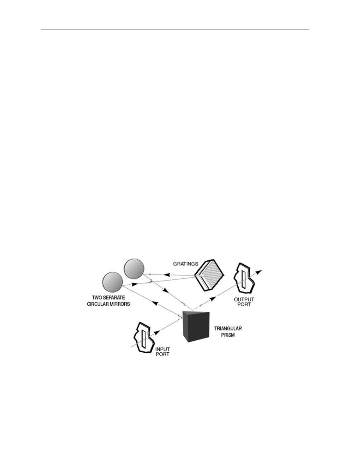
2.1 23BOPTICAL CONFIGURATION
The optical design of the Cornerstone 130B is based on an out-of-plane version of an Ebert-Fastie
monochromator. The input and output ports are in line with each other, simplifying system
alignment. The optical configuration is designed to ensure high resolution and maximum
throughput. This F/3.9 monochromator is optimized to provide excellent stray light rejection while
minimizing aberrations. A high precision motor is used to select the desired wavelength and switch
between diffraction gratings quickly, without sacrificing performance.
Figure 1: Optical Configuration of the Cornerstone 130B
Page 10
90088262 MCS130B
CORNERSTONE 130B MONOCHROMATORS
10
2.2 24BSTRAY LIGHT REJECTION
Stray light may have a variety of origins. Its presence may be caused by a wide variety of design
and manufacturing factors. The level of stray light due to the dispersed radiation inside the
monochromator is affected by the design of the instrument, its baffles, and interior finish. The
Cornerstone 130B incorporates a sophisticated design, proven materials, and a quality
manufacturing system to ensure high stray light rejection.
The amount of stray light measured on top of true signal will depend on many experimental factors
as well as the performance of the instrument. When comparing stray light specifications, it is
important to compare values that were measured under identical circumstances. The spectral
distribution of the source and the response of the detection system are often the dominant factors
when determining a stray light value.
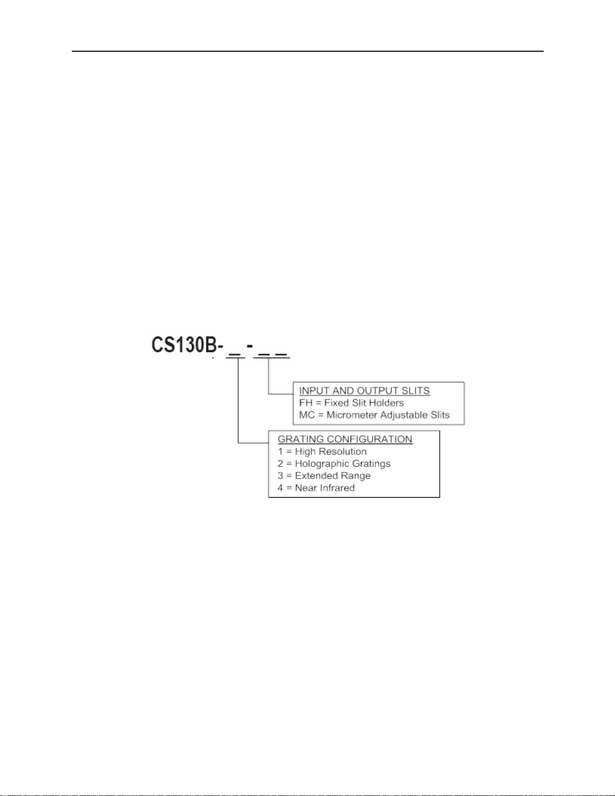
2.3 25BAVAILABLE MODELS
The model number of each Cornerstone monochromator reflects its features. Refer to the part
number code to determine the features present in the instrument. If the model number differs from
the code, it is a Special Order configuration. In that case, refer to the Sales Order for the
instrument for more information.
Figure 2: Model Number Codes
Page 11
90088262 MCS130B
CORNERSTONE 130B MONOCHROMATORS
11
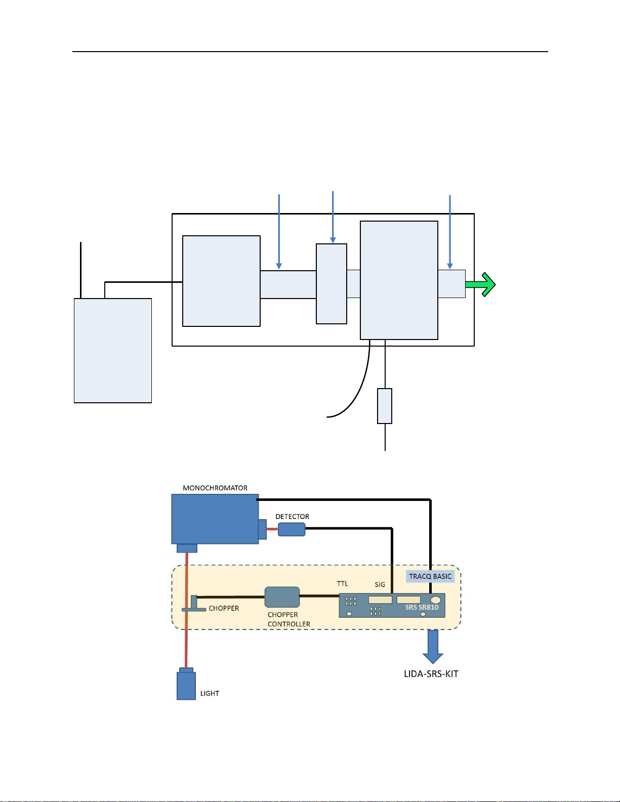
2.4 26BTYPICAL APPLICATIONS
The applications for the Cornerstone 130B monochromator are practically limitless. Here we
present two examples: a tunable monochromatic light source and an optically chopped light
source used with a lock-in digital amplifier to extract small signal levels from background radiation.
All components shown are available from Newport.
Figure 3: Tunable Monochromatic Light Source
Figure 4: Monochromator with Lock-In Digital Amplifier
Interconnect
Power Adapter
with Power Cord
USB Cable to
Computer
Collimating
Lens
Cornerstone
130B
Monochromator
Power Cord
Collimating
and
Focus Optics
Light Source
Motorized
Filter
Wheel
Tunable monochromatic light
source on mounting plate
Monochromatic
Light Output
Arc Lamp
Power Supply
Page 12
90088262 MCS130B
CORNERSTONE 130B MONOCHROMATORS
12
3 2BINITIAL SETUP
3.1 27BWHAT’S INCLUDED
• Two diffraction gratings, installed and aligned
• Electronic shutter at input port
• A choice of micrometer adjustable slits or fixed slit holders at the input and output ports
• Electronics interface for RS232 or USB communication
• An MPT plug to accept a hose barb to purge the instrument compartment for measurements
below 180 nm (actual capability is grating configuration dependent)
• LabVIEW™ based utility software
• Application Programming Interface (API) for LabVIEW™ with examples
• Certificate of Calibration
• Monochromator Power Supply
• Line cords based on geographic location
• User’s manual
3.2 28BUNPACKING
Remove all items from the shipping containers and verify each item is accounted for. The
instrument is carefully packaged to minimize the possibility of damage during shipment. Inspect
the shipping box for external signs of damage or mishandling. Inspect the contents for damage.
If any item is missing or damaged, immediately contact Newport or the representative from whom
the system was purchased.
It is suggested to save the packaging material and shipping container, in case the equipment
needs to be relocated at a future date.
WARNING
Do not attempt to operate this equipment if there is evidence of
shipping damage or there is suspicion that the equipment will not
operate correctly. Damaged equipment may present hazards.
3.3 29BCHOOSING A LOCATION
Choose an installation location where the power requirements can be met for the monochromator,
as well as the rest of the optical system. Be sure power is not applied to the system until the setup
has been completed and all electrical connections made.
Ensure that there is easy access to the monochromator’s power switch and the electrical outlet.
Page 13
90088262 MCS130B
CORNERSTONE 130B MONOCHROMATORS
13
3.4 30BMOUNTING OPTIONS
The ability to mount the monochromator simplifies setup and alignment of the optical system. The
mounting plates or kits also help ensure consistent results over time, as the monochromator
cannot be accidentally moved out of position. The following options are available for securing the
Cornerstone 130B:
• Mounting plate
• Mounting kit to couple with Oriel’s Research Lamp Housings
• Optical rods
The 74006 Mounting Plate is used to secure a Cornerstone 130B Monochromator to an inch or
metric optical table. The plate adds 0.25 inch [6.35 mm] to the optical height. If the Cornerstone
130B will be used with Oriel’s research lamp housing, consider using the 74017 mounting kit.
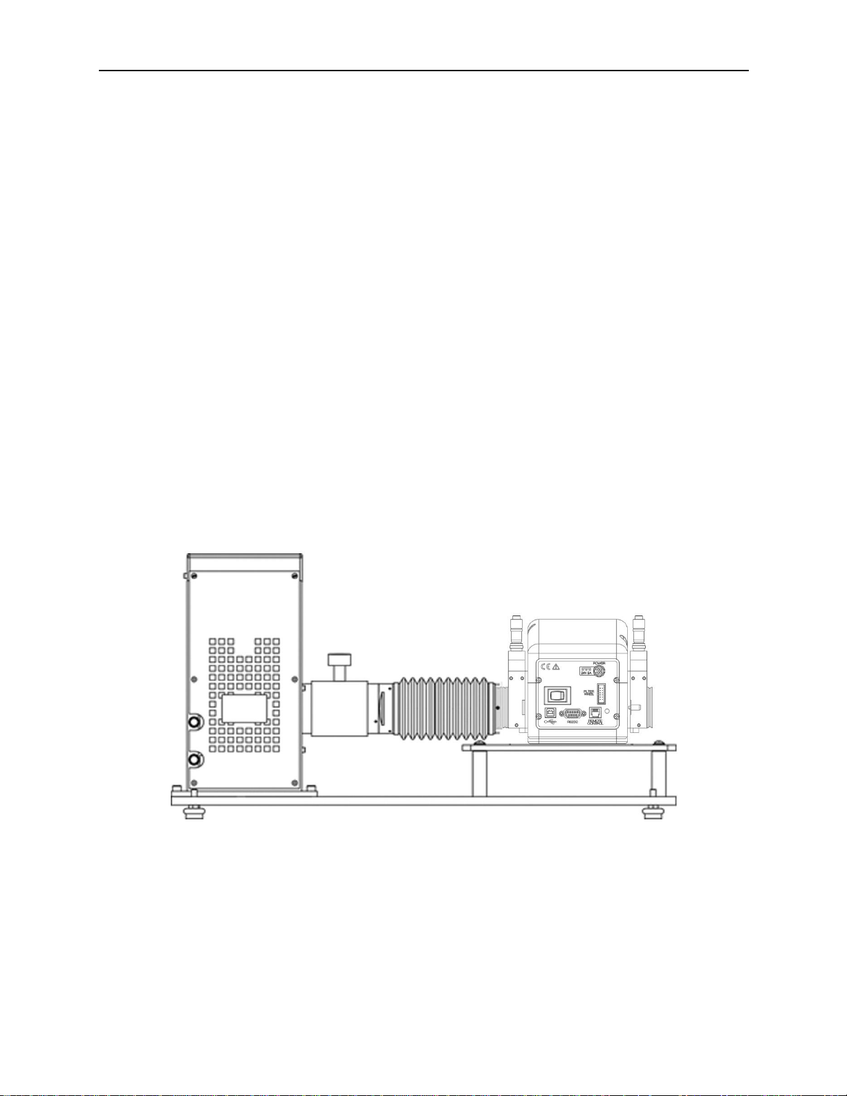
The 74017 Mounting Kit connects the Cornerstone 130B monochromator to an arc lamp or quartz
tungsten halogen light source. This kit is compatible with Oriel's Research Lamp Housings, which
hold 50 to 250 watt lamps. It includes a base plate, a flexible light shield, a 1.5-inch diameter
focusing lens and lens holder. All the hardware required to mount the lamp housing and
monochromator to the base plate is provided. The mounting kit's base plate comes with four
adjustable leveling feet. The feet may be removed to secure the base plate to an inch or metric
optical table.
The most economical option is to use optical rods and rod holders to mount the Cornerstone 130B
to an optical table or breadboard. On the monochromator’s mounting surface, four #1/4-20
threaded holes may be used to install standard optical rods. Care should be taken to ensure the
instrument is level and secured well enough that its location remains consistent over time, even if
the instrument is bumped or components coupled to the ports.
Figure 5: Model 74017 Mounting Kit
Page 14
90088262 MCS130B
CORNERSTONE 130B MONOCHROMATORS
14
3.5 31BELECTRICAL AND COMPUTER CONNECTIONS
Before powering up the system for the first time, it is suggested to have a qualified electrician
verify the wall socket to be used with the instrument meets the requirements for operation as
noted.
Before making any electrical connections, verify the front panel power switch is in the off position
for the monochromator.
WARNING
To avoid electric shock, connect the instrument to properly earthgrounded, 3-prong receptacles only. Failure to observe this
precaution can result in severe injury or death.
The line voltage requirement is as follows:
Monochromator Power Adapter 100 to 240 VAC, 47-63 Hz
The monochromator conforms to CE standards for both safety and EMC. During normal use, this
equipment will not pose any electrical hazards to the user. Read all warnings before installing or
operating this system. If there are any questions or concerns, contact Oriel Instruments or the
regional sales representative for Newport.
ELECTRICAL SHOCK
Never attempt to open the lamp power supply or monochromator
power adapter. These items do not contain any user serviceable
parts. Failure to follow this warning can result in severe injury or
death.
The monochromator’s power adapter connects to an AC wall socket and supplies DC volt age to
the instrument. Do not open the monochromator cover and attempt to work inside without first
turning the instrument off and disconnecting the power cord from the AC mains.
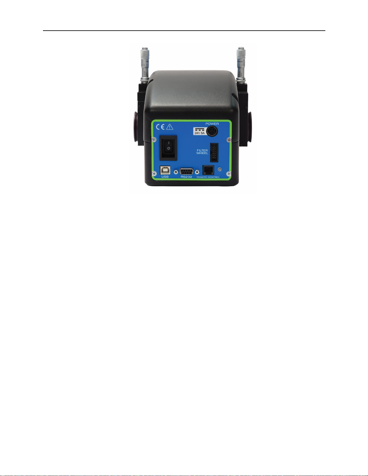
The ribbon cable connecting the monochromator to the optional filter wheel is installed before
the system ships out. The monochromator provides power to the filter wheel and allows the user
to select which filter is placed in the optical path.
Ensure the monochromator power switch is in the off position (marked as O). Then connect the
power adapter to the monochromator, as shown. Insert the power cord provided into the power
adapter and connect to the AC mains.
Connect the USB or RS232 cable to the monochromator. Plug the other end of the cable into the
computer only after any software controlling the monochromator has been installed.
Page 15
90088262 MCS130B
CORNERSTONE 130B MONOCHROMATORS
15
Figure 6: Monochromator Connections
A USB cable (model 70044) and RS232 cable (model 70040) are included with each Cornerstone
130B.
If using a commercially available USB/GPIB or USB/RS232 converter cable, the driver for this cable
must be installed before communication to the monochromator can be established.
Follow the instructions provided in the Quick Start Guide to install the utility software onto a
computer.
Page 16

90088262 MCS130B
CORNERSTONE 130B MONOCHROMATORS
16
4 3BSHUTTER
An electronic shutter is integrated into the Cornerstone B monochromator’s design. It is mounte d i n s ide
the housing at the input port. This shutter is normally closed.
The shutter is used to close the light path when output light is not required. This allows the light source to
remain on, and therefore remain warmed up, so that it continues to provide stable performance.
Additionally, restarting a lamp results in wear of the filament (with quartz tungsten halogen lamps) or wear
of the anode/cathode (with arc lamps). Therefore, when the light is not needed during short periods,
closing the shutter is suggested.
Diffraction gratings are mounted on a precision rotation stage inside the monochromator. When the
monochromator switches between diffraction gratings, the changing angle of the grating causes light to
be diffracted at various wavelengths. This includes white light, which is output at a higher power than
other individual wavelengths. In order to prevent saturation of a detection system, it is suggested to close
the shutter temporarily while changing gratings. It is especially important to prevent saturation and
possible damage when using a photomultiplier tube.
A scan may be completed while the shutter is closed to perform background subtraction calculations on
subsequent scans completed while the shutter is open.
Please note that the shutter is not designed to block high power direct light. When using a 450W or
greater light source, heat mitigation strategies should be employed. For example, Oriel offers liquid filters
to protect the shutter, filters, and other items to prevent potential heat damage.
Page 17
90088262 MCS130B
CORNERSTONE 130B MONOCHROMATORS
17
5 4BINPUT AND OUTPUT SLITS
To operate any monochromator, slits are required at the input and output port. The slit assemblies
offered with the Cornerstone 130B all have 1.5-inch male flanges, allowing them to be easily connected to
the wide variety of Oriel accessories and instruments.
Note: The slits need to be the same width and height at the input and output ports. A wider input slit
when compared to the output slit results in more stray light inside the instrument. A wider output slit with
respect to the input slit will not increase throughput.
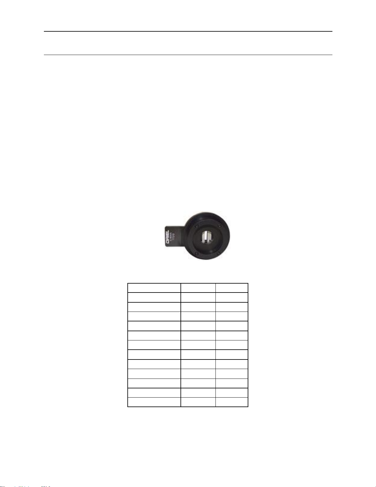
5.1 32BFIXED SLITS
The fixed slits slide into the 77294 holders at the input and output port. The width and height
cannot be adjusted, but may be individually replaced with other slit sizes. Fixed slits are a low cost
alternative to micrometer adjustable slits, and provide excellent repeatability. They are a good
choice when only a few slit sizes are required.
Fixed slits are sold separately to allow customized choices based on the needs of the application.
When ordering, be sure to purchase two fixed slits of the same model – one for the input port, and
the other for the output port. Insert the slit as shown, with the label facing outward. Be sure that it
is fully inserted into the holder’s slot to ensure the best performance and repeatability.
Figure 7: A Fixed Slit Installed into the Holder
Fixed Slit Model
Width
Height
77222
10 µm
2 mm
77221
50 µm
3 mm
77220
25 µm
3 mm
77219
50 µm
6 mm
77218
120 µm
18 mm*
77217
280 µm
18 mm*
77216
600 µm
18 mm*
77215
760 µm
18 mm*
77214
1.24 mm
18 mm*
77213
1.56 mm
18 mm*
77212
3.16 mm
18 mm*
77211
6.32 mm
18 mm*
*Actual slit height is 18 mm, usable height is 12 mm.
Figure 8: Available Fixed Slits Table
Page 18
90088262 MCS130B
CORNERSTONE 130B MONOCHROMATORS
18
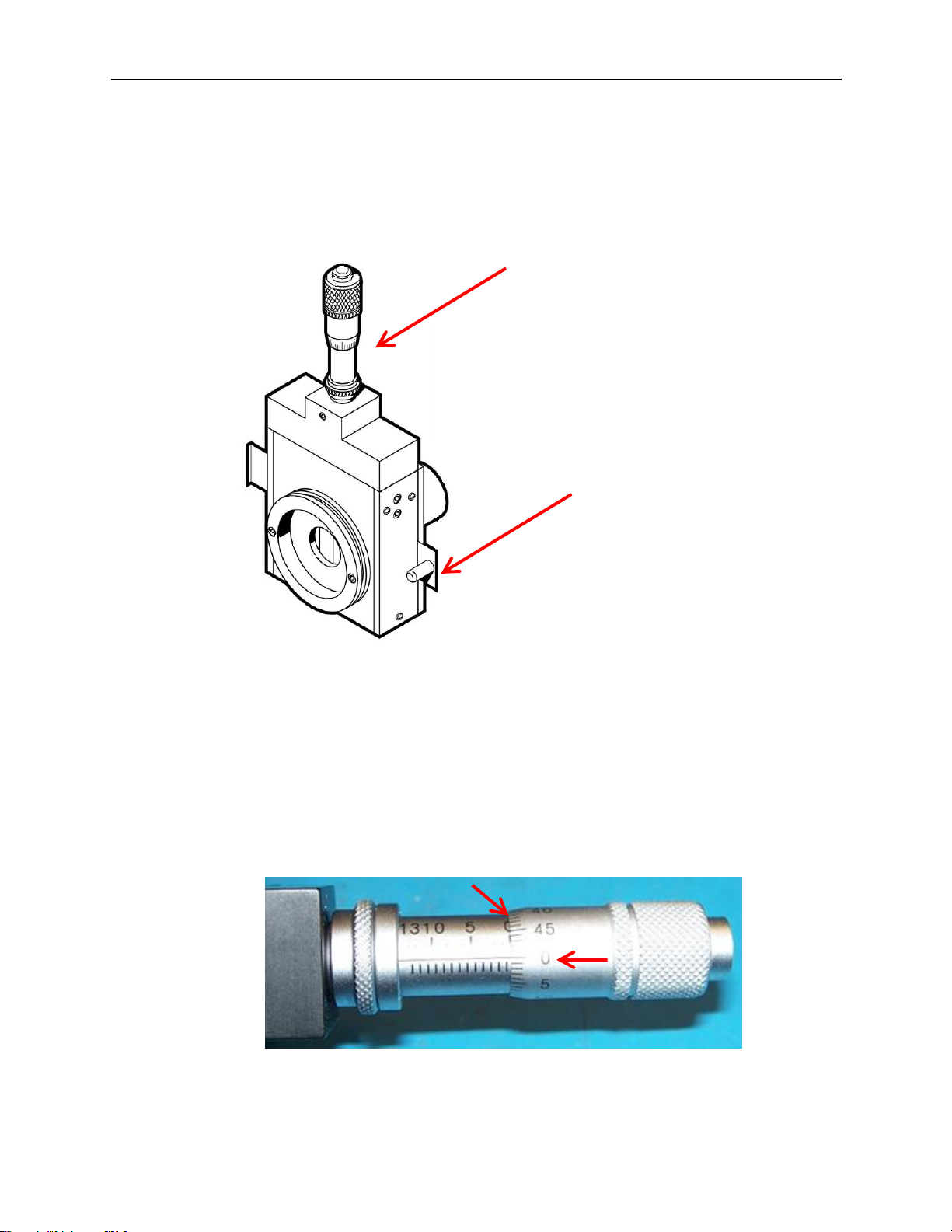
5.2 33BMICROMETER ADJUSTABLE SLITS
Micrometer adjustable slit assemblies are continuously variable from fully closed (4 µm) to 3 mm
width. A height adjustment slide allows variation in the height from 3 to 12 mm. Benefits of the
micrometer adjustable slits are flexibility and high throughput. This type of slit is designed primarily
for versatility and convenience in changing resolution and throughput, which are related to the slit
width.
Figure 9: A Micrometer Adjustable Slit
The slit width setting is read on the micrometer. A set of numbers go around the turning dial.
Another set of numbers are located on the shaft. When the zeroes in both these locations line up,
the slit is fully closed. Turning the dial clockwise advances the dial position further down on the
shaft, closer to the body of the micrometer. This opens the slit.
Use a 10x multiplier to convert the micrometer reading to the actual slit opening size. For
example, turning the dial one full revolution starting from the fully closed position will give a
reading of 50 on the micrometer. Using the multiplier, this indicates the micrometer width is set to
500 um. If unsure of the reading, begin at the fully closed position and add up each full revolution
made.
Figure 10: A Fully Closed Micrometer Adjustable Slit
The micrometer is used to make the slit
narrow or wide
The slide is used to
change the slit height
Page 19
90088262 MCS130B
CORNERSTONE 130B MONOCHROMATORS
19
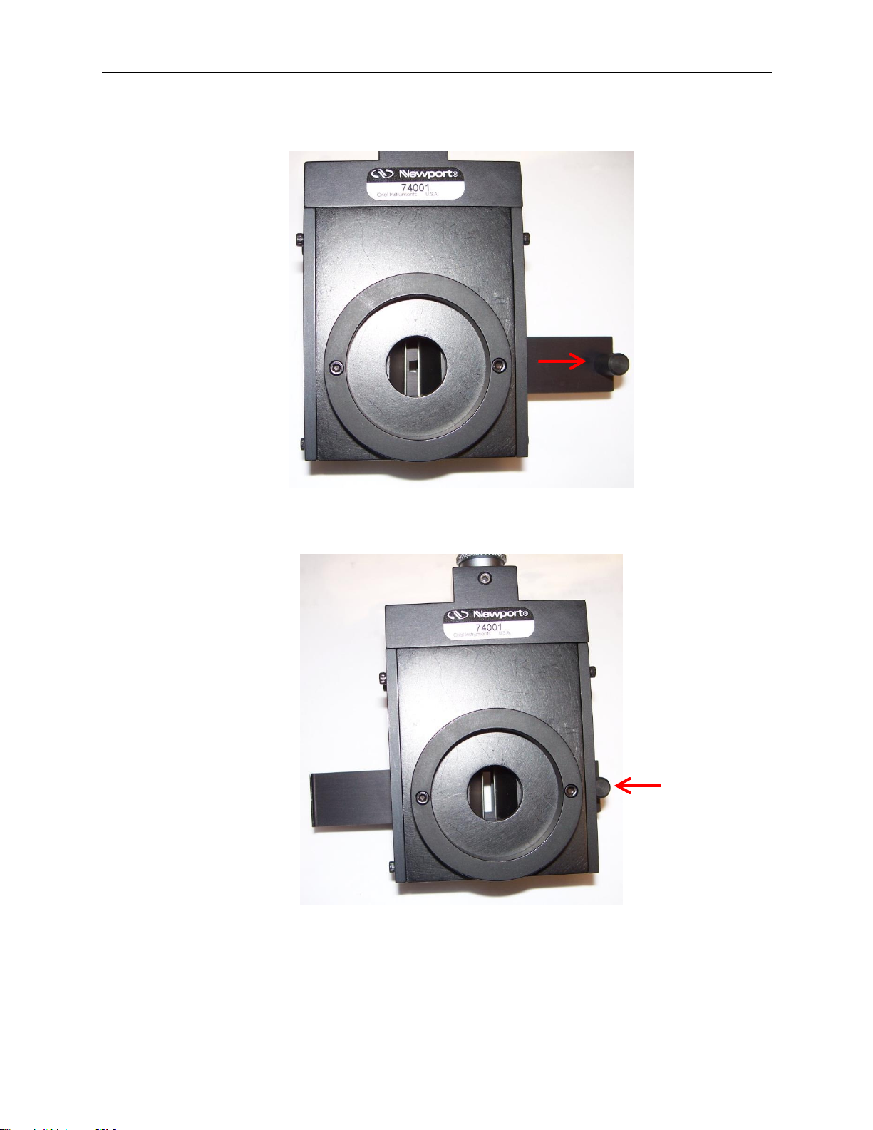
The slit height is continuously adjustable. Pull the lever out for the shortest height. Push the slide
in for the tallest height setting.
Figure 11: Shortest Micrometer Adjustable Slit Height
Figure 12: Tallest Micrometer Adjustable Slit Height
Page 20
90088262 MCS130B
CORNERSTONE 130B MONOCHROMATORS
20
6 5BDIFFRACTION GRATINGS
Diffraction gratings are used to disperse light; that is to spatially separate light of different wavelengths.
They have replaced prisms in most fields of spectral analysis. Two gratings are installed into the
Cornerstone 130B monochromator. In general, the grating with the highest efficiency is chosen at a
particular wavelength. The optional TracQ™ Basic Data Acquisition and Radiometery Software allows
users to set up a specific grating switchover wavelength, so the most appropriate grating will
automatically be chosen while performing a scan over a range of wavelengths.
The Cornerstone 130B monochromators feature diffraction gratings produced by Richardson Gratings.
Both Oriel Instruments and Richardson Gratings are part of Newport, and have a long history of working
together to design monochromators that are appropriate for a wide variety of applications.
A tutorial on grating physics may be found in the Appendix of this user’s manual.
The photo below illustrates a diffraction grating mounted into a holder for installation into the Cornerstone
130B monochromator. An unmounted grating cannot be installed by the user in the field; gratings must
be installed onto the appropriate mount for the Cornerstone 130B monochromator and aligned at the
factory.
Figure 13: Grating Installed onto Mount
Page 21
90088262 MCS130B
CORNERSTONE 130B MONOCHROMATORS
21
6.1 34BGRATING TYPES
Ruled grating masters are produced using a ruling engine with an extremely fine cutting tool.
Holographic gratings (also called interference gratings) are produced by recording interference
fringes in photoresist. The different techniques cause some differences in performance.
Holographic gratings are most frequently available at high groove densities due to manufacturing
limitations inherent in the technology. They are generally favored for work in the UV and through
the visible to about 600 nm. Holographic gratings produce less scattering, thereby reducing stray
light inside the monochromator.
Ruled gratings typically have higher efficiencies. They may have periodic errors in the grating
grooves caused by minor defects in the ruling machine, resulting in anomalous readings or
“ghosts”. Holographic gratings do not suffer from ghosts, so interpretation of line spectra is
simplified.
The signal-to-noise ratio (SNR) is the ratio of diffracted energy to unwanted light energy. Although it
may be assumed that increasing diffraction efficiency will increase SNR, stray light usually plays the
limiting role in the achievable SNR for a grating system. Note that the actual signal to noise ratio will
depend on the spectral content of the incident light and the detector.
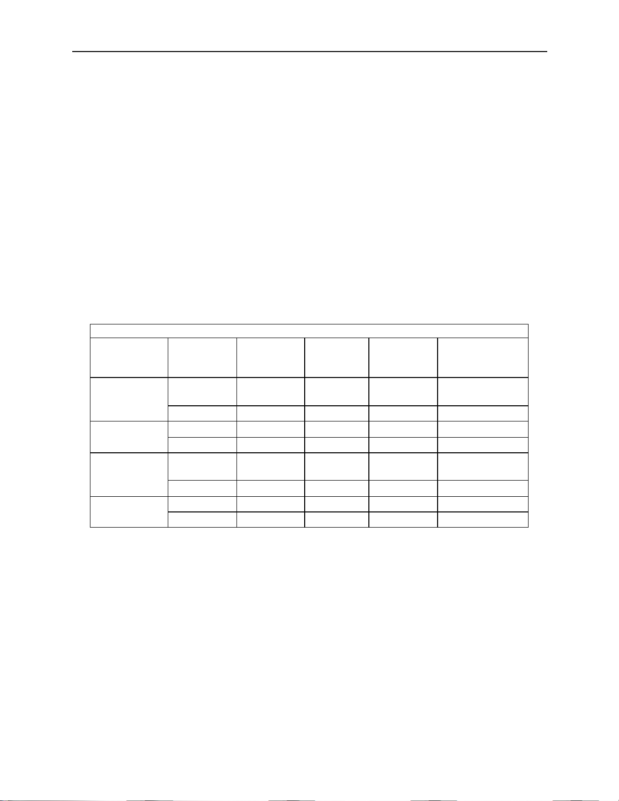
Figure 14: Grating Properties Table
GRATING PROPERTIES
Configuration
Grating
Position
Type
Groove
Density
(lines/mm)
Blaze
Wavelength
(nm)
Reciprocal
Dispersion
(nm/mm)
High
Resolution
#1
Ruled
2400
240
2.7
#2
Ruled
1200
500
5.3
Holographic
#1
Holographic
1200
250
5.5
#2
Holographic
1800
500
3.3
Extended
Range
#1
Ruled
600
400
11
#2
Ruled
600
1000
10.6
Near IR
#1
Ruled
600
1000
10.6
#2
Ruled
300
2000
21.2
Page 22

90088262 MCS130B
CORNERSTONE 130B MONOCHROMATORS
22
6.2 35BGRATING EFFICIENCY AND BLAZING
Efficiency and its variation with wavelength and spectral order are important characteristics of a
diffraction grating. For a reflection grating, efficiency is defined as the energy flow (power) of
monochromatic light diffracted into the order being measured, relative either to the energy flow of
the incident light (absolute efficiency) or to the energy flow of specular reflection from a polished
mirror substrate coated with the same material (relative efficiency). Efficiency is defined similarly for
transmission gratings, except that an uncoated substrate is used in the measurement of relative
efficiency.
High-efficiency gratings are desirable for several reasons. A grating with high efficiency is more
useful than one with lower efficiency in measuring weak transition lines in optical spectra. A grating
with high efficiency may allow the reflectivity and transmissivity specifications for the other
components in the spectrometer to be relaxed. Moreover, higher diffracted energy may imply lower
instrumental stray light due to other diffracted orders, as the total energy flow for a given
wavelength leaving the grating is conserved (being equal to the energy flow incident on it minus any
scattering and absorption).
Control over the magnitude and variation of diffracted energy with wavelength is called blazing, and
it involves the manipulation of the micro-geometry of the grating grooves. The energy flow
distribution (by wavelength) of a diffraction grating can be altered by modifying the shape of the
grating grooves. The blaze wavelength is the wavelength where the grating efficiency is enhanced
by shaping the grating grooves. Although holographic gratings are not shaped like ruled gratings,
the peak grating efficiency wavelength is also referred to as the blaze wavelength.
The choice of an optimal efficiency curve for a grating depends on the specific application. Often
the desired instrumental efficiency is linear; that is, the intensity of light transformed into signal at
the image plane must be constant across the spectrum. To approach this as closely as possible,
the spectral emissivity of the light source and the spectral response of the detector should be
considered, from which the desired grating efficiency curve can be derived. Usually this requires
peak grating efficiency in the region of the spectrum where the detectors are least sensitive.
In many instances, the diffracted power depends on the polarization of the incident light. For
completely unpolarized incident light, the efficiency curve will be exactly halfway between the P and
S efficiency curves. Anomalies are locations on an efficiency curve (efficiency plotted vs.
wavelength) at which the efficiency changes abruptly. These sharp peaks and troughs in an
efficiency curve are sometimes referred to as Wood's anomalies.
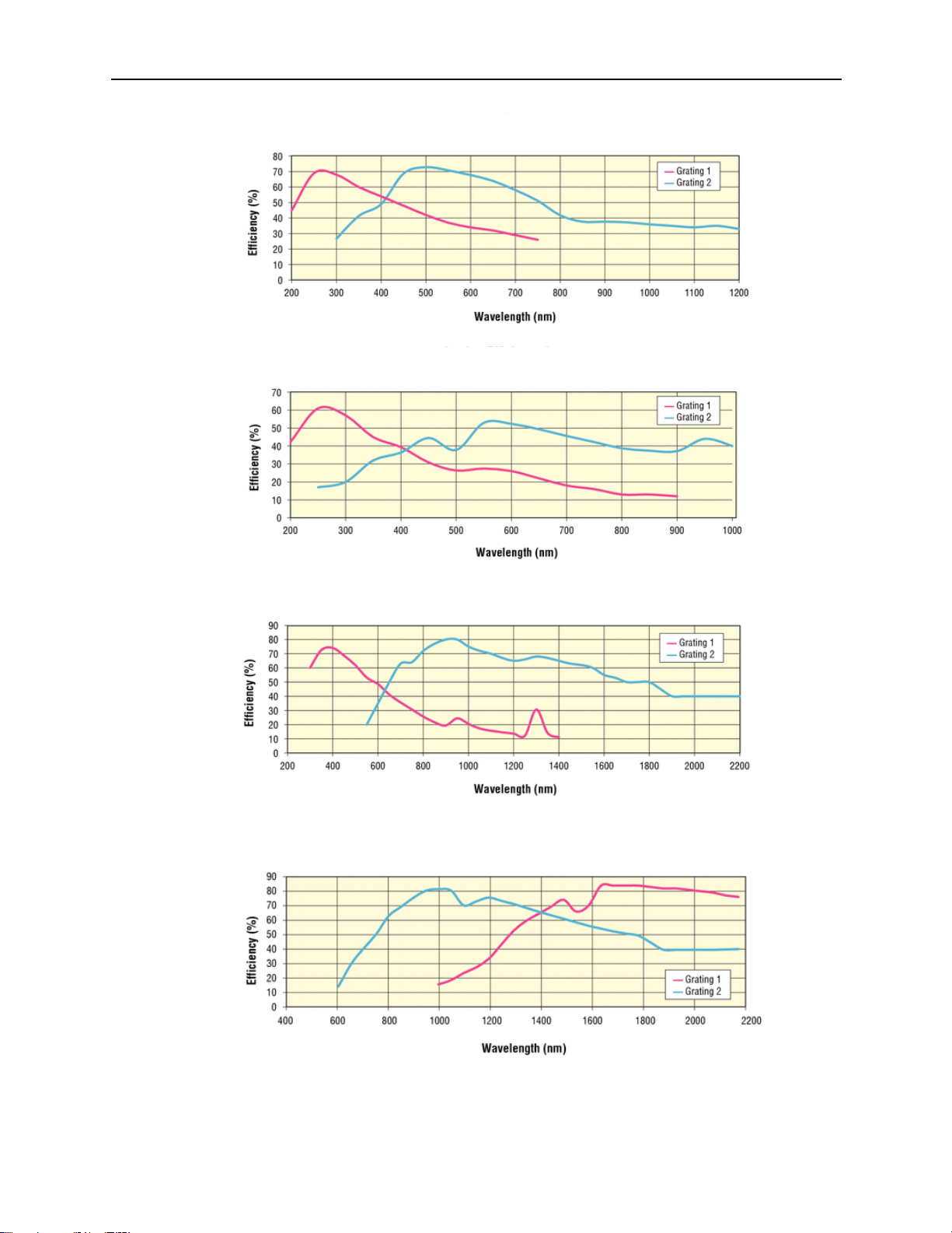
The efficiency curves shown are relative (not absolute) and were measured using an in-plane near
Littrow configuration. Please use the curves as a guide and not as absolute data. Grating
diffraction is dependent on the polarization of the radiation incident on the grating.
Software such as the Mono Utility and TracQ Basic may be configured to switch between gratings
at a specific wavelength. Typically, the most efficient grating is selected, so this switchover
wavelength would be where the two efficiency curves meet. To determine empirically the ideal
switchover wavelength, the output should be measured by an optical detector. Run a scan in the
crossover region using only Grating 1. Repeat the scan using only Grating 2. Where the detector
readings are closest is the optimal switchover wavelength.
If the selected grating’s efficiency has a sudden increase or decrease at a particularly critical
wavelength and the application demands extreme accuracy, it may be more desirable to select the
grating with the more gradual change in efficiency.
Page 23
90088262 MCS130B
CORNERSTONE 130B MONOCHROMATORS
23
Figure 15: Grating Efficiency Curves for CS130B Monochromator Pre-Configured Models
High Resolution Configuration
Holographic Grating Configuration
Extended Range Configuration
Near Infrared Configuration
Page 24

90088262 MCS130B
CORNERSTONE 130B MONOCHROMATORS
24
6.3 36BPOLARIZATION EFFECTS
The diffraction efficiency from a grating usually depends on the polarization of the radiation
incident on the grating. There can be significant differences between the efficiency for radiation
with the electric field vector parallel to the grating grooves and radiation with the electric vector
perpendicular to the grooves.
Radiation with the electric vector restricted to a specific direction is linearly polarized. Linearly
polarized radiation with the electric vector parallel to the grooves is P-polarized. Radiation
polarized perpendicular to the grooves is S-polarized. For Oriel’s monochromators and
spectrographs, P-polarized radiation has the polarization axis parallel to the entrance slit. In most
laboratory applications with the instrument sitting on its mounting surface on a horizontal bench or
optical table, P-polarized radiation is vertically polarized.
Note: this definition of S- and P-polarization for diffraction gratings does not follow the general
rules for S and P-polarization for optics where the plane of incidence, rather than the grooves, are
used to define parallel and perpendicular.
The graphs for the Cornerstone 130B configurations have one efficiency curve per grating. This is
representative of 45-degree polarization, which is the average of the P-polarization and Spolarization efficiency curves.
Typically, the efficiency curve for P-polarized light peaks slightly lower than the nominal blaze
wavelength and smoothly declines to 0% at about three times the blaze wavelength. The curves
for P-polarization are generally smooth, without dramatic changes in direction or sharp features.
The curves for S-polarized light peak slightly above the nominal blaze wavelength and decline.
However, the efficiency can recover dramatically and show good efficiency over a broader
wavelength range. The S-polarization curves can show sharp features (anomalies) which
complicate data deconvolution from spectral scans.
If a source is being measured close to an anomaly, then the real feature may be dramatically
distorted. If possible, a grating should be selected (or polarization) which has no significant
anomaly in the spectral region of interest. Contact a Newport sales engineer for more information
on the effects of polarized light in terms of grating efficiency.
Page 25

90088262 MCS130B
CORNERSTONE 130B MONOCHROMATORS
25
7 6BMONOCHROMATOR RESOLUTION
Gratings are available in various groove densities (i.e. lines/mm). Higher groove densities give higher
reciprocal dispersion and therefore higher resolution. The monochromator bandpass with a 1200
lines/mm grating is half that of the same arrangement with a 600 lines/mm grating. Note that this simple
relationship is not accurate for slit widths below 50 µm, as the optical aberrations begin to play a role in
the bandpass and resolution.
Using a grating with a high groove density may increase resolution, but the spectral range narrows. The
dispersion of a grating changes inversely with the groove density. If the groove density is halved, the
dispersion is doubled. A monochromator mechanism can only tilt the grating through a limited range of
angles. The angle and groove density determine the transmitted wavelength.
The gratings can be tilted to 0 degrees, so the lowest possible wavelength for a UV grating is set by the
transmittance of air at about 180 nm. A MPT plug is available to connect a hose barb and purge the
monochromator compartment with nitrogen, if desired. The ability to output wavelengths below 180 nm is
also dependent on the efficiency characteristics of the grating.
The following graphs are intended to illustrate the effects of slit width selection, in terms of throughput and
resolution. This data was taken using Oriel’s Tunable Light Source (TLS) systems, using various slit
widths to change the resolution. The TLS systems employ a Cornerstone 130 monochromator.
Figure 16: Resolution vs. Throughput
Page 26

90088262 MCS130B
CORNERSTONE 130B MONOCHROMATORS
26
7.1 37BDETERMINING RESOLUTION
All monochromators featuring fixed slit holders require fixed slits to be installed at the input and
output ports. Fixed slits are ordered separately, and should be the same size at the input and
output ports.
Micrometer adjustable slits allow for continuous variation of the width and height. Use the table
below for guidance on resolution vs. slit width. For slit widths not specified in the table, multiply the
micrometer adjustable slit width setting (mm) by the reciprocal dispersion (nm/mm) to calculate the
resolution for each grating.
Resolution is calculated for each grating at the grating's blaze wavelength, i.e. the wavelength with
the greatest efficiency. Actual performance is determined by the monochromator wavelength
accuracy, precision and calibration. Newport suggests having the monochromator recalibrated
annually by a qualified service technician.
Calculation of Resolution Based on Fixed Slit Selection
Fixed Slit
Slit
Width
Grating 1
Grating 2
Grating 1
Grating 2
High Resolution Configuration
Holographic Configuration
77222
10 µm*
0.03 nm
0.05 nm**
0.06 nm
0.03 nm
77221
50 µm*
0.14 nm
0.27 nm
0.28 nm
0.17 nm
77220
25 µm*
0.07 nm
0.13 nm**
0.14 nm
0.08 nm
77219
50 µm*
0.14 nm
0.27 nm**
0.28 nm
0.17 nm
77218
120 µm
0.32 nm
0.64 nm
0.66 nm
0.40 nm
77217
280 µm
0.76 nm
1.5 nm
1.5 nm
0.9 nm
77216
600 µm
1.6 nm
3.2 nm
3.3 nm
2.0 nm
77215
760 µm
2.1 nm
4.0 nm
4.2 nm
2.5 nm
77214
1.24 mm
3.3 nm
6.6 nm
6.8 nm
4.1 nm
77213
1.56 mm
4.2 nm
8.3 nm
8.6 nm
5.1 nm
77212
3.16 mm
8.5 nm
16.7 nm
17.4 nm
10.4 nm
77211
6.32 mm
17.1 nm
33.5 nm
34.8 nm
20.9 nm
* For slits with widths of 50 µm or less, aberrations begin to play a role in the actual achievable
resolution. The values noted above, unless otherwise stated, are calculations based on the slit
widths and grating dispersions.
** Empirically measured resolution values shown which differ from calculations due to aberrations
present when using narrow slit widths.
Page 27

90088262 MCS130B
CORNERSTONE 130B MONOCHROMATORS
27
Calculation of Resolution Based on Fixed Slit Selection
Fixed Slit
Slit
Width
Grating 1
Grating 2
Grating 1
Grating 2
Extended Range Configuration
VIS-NIR Configuration
77222
10 µm*
0.11 nm
0.11 nm
0.11 nm
0.21 nm
77221
50 µm*
0.55 nm
0.53 nm
0.53 nm
1.06 nm
77220
25 µm*
0.28 nm
0.27 nm
0.27 nm
0.53 nm
77219
50 µm*
0.55 nm
0.53 nm
0.53 nm
1.06 nm
77218
120 µm
1.32 nm
1.27 nm
1.27 nm
2.5 nm
77217
280 µm
3.08 nm
2.97 nm
2.97 nm
5.9 nm
77216
600 µm
6.6 nm
6.4 nm
6.4 nm
12.7 nm
77215
760 µm
8.4 nm
8.1 nm
8.1 nm
16.1 nm
77214
1.24 mm
13.6 nm
13.1 nm
13.1 nm
26.3 nm
77213
1.56 mm
17.2 nm
16.5 nm
16.5 nm
33.1 nm
77212
3.16 mm
34.8 nm
33.5 nm
33.5 nm
67.0 nm
77211
6.32 mm
69.5 nm
67.0 nm
67.0 nm
134.0 nm
* For slits with widths of 50 µm or less, aberrations begin to play a role in the actual achievable
resolution. The values noted above, unless otherwise stated, are calculations based on the slit
widths and grating dispersions.
** Empirically measured resolution values shown which differ from calculations due to aberrations
present when using narrow slit widths.
Figure 17: Some of the Fixed Slit Sizes Available
Page 28

90088262 MCS130B
CORNERSTONE 130B MONOCHROMATORS
28
8 7BGETTING LIGHT INTO A MONOCHROMATOR
8.1 38BACCEPTANCE PYRAMID
The figure below shows the optical path of the light input to the instrument. The monochromator
has an acceptance pyramid, often described by an F/#. The position and dimensions of the
internal optics determines the pyramid. The optical equivalent is a grating image located behind
the slit as shown in below. Only light that passes through the slit in the direction of this grating
image is useful.
Always fill the acceptance pyramid of the instrument with light.
Figure 18: Acceptance Pyramid of Monochromator
Figure 19: Grating Correctly “Filled” with Light
Page 29

90088262 MCS130B
CORNERSTONE 130B MONOCHROMATORS
29
8.2 39BF NUMBER MATCHING
The Cornerstone 130B monochromator is an F/3.9 instrument. Without matching the F/# of the
incoming light beam, stray light increases and throughput of desired signal suffers. To illustrate
this, the photos below show a fiber optic cable placed at the entrance of a monochromator. Fibers
are typically F/2. The Oriel model 77529 may be used to match the F/# to the monochromator.
Figure 20: Mismatched F Numbers Resulting in Stray Light
Figure 21: F Number Matcher Used with Fiber Optic Cable
Page 30

90088262 MCS130B
CORNERSTONE 130B MONOCHROMATORS
30
9 8BBLOCKING HIGHER ORDER RADIATION
Detailed information regarding grating physics can be found in the Appendix of this user’s manual. A
summary of grating physics is noted here.
• Only wavelengths that satisfy the grating equation pass through the output port of the
instrument.
• The remainder of the light is scattered and absorbed inside the instrument.
• The grating is rotated to bring different wavelengths of light in line with the output.
• A grating creates interference patterns when light is shown onto it.
• Different wavelengths interfere at different angles off the grating.
• Light occurs when there is constructive interference, called grating orders.
• All wavelengths interfere at one specific angle of the grating. This is called the “zero order”.
• When a parallel beam of monochromatic light is incident on a grating, the light is diffracted from
the grating in directions corresponding to m = -2, -1, 0, 1, 2, 3, etc.
• When a parallel beam on polychromatic light is incident on a grating, the light is dispersed so
that each wavelength satisfies the Grating Equation.
• Usually only the first order is desired. The other wavelengths in higher orders may need to be
blocked.
• The input spectrum and detector sensitivity determine whether order sorting or blocking
filters are needed.
9.1 40BORDER SORTING FILTERS
For meaningful spectral measurements, care should be taken to remove unwanted orders of
radiation, particularly if the input radiation is intense or the detector more sensitive at the higher
order.
Erroneous measurements may be taken because what was thought to be a measurement with a
single wavelength was actually a measurement using radiation at that wavelength – but
contaminated with higher order radiation. Consider using Newport’s Colored-Glass Alternative
Filters for blocking higher order diffraction.
Example 1:
• A monochromator is set to output 600 nm and the signal read by a UV-enhanced Si
detector with a spectral responsivity range of 200 nm to 1100 nm.
• Additional output will be 300 nm (600/2) and 200 nm (600/3). These are the second
and third order wavelengths.
• The second and third order wavelengths are within the responsivity range of this
detector.
• In order to block these extra orders, a filter that blocks wavelengths below 300nm
and transmits light at 600nm needs to be inserted in the optical path.
Example 2:
• A monochromator is set to output 1200 nm and the signal read by a Ge detector
with a spectral responsivity range of 700 nm to 1800 nm.
• Additional output will be 600 nm (1200/2) and 400 nm (1200/3). These are the
second and third order wavelengths.
• No order sorting filter is needed as the second and third order wavelengths are
outside the responsivity range of this detector.
Page 31

90088262 MCS130B
CORNERSTONE 130B MONOCHROMATORS
31
10 9BCOMMUNICATION METHODS
In order to satisfy the needs of as many users as possible, the Cornerstone 130B is designed to be
controlled from a variety of sources.
The Cornerstone 130B is capable of automatically controlling an optional filter wheel, Models USFW-100
or 74010. It is also able to interface with the motorized filter wheel included with Oriel’s APEX2 light
sources. These filter wheels hold up to six 1-inch [25.4 mm] diameter filters. Neutral density filters can be
used for intensity adjustment. Order sorting filters may be installed to block higher order diffraction.
The filter wheel can be mounted to the male flanges of the monochromator slits or slit holders. The filters
are mounted external to the monochromator. Thus, the refractive index and thickness of the filters do not
significantly affect the focal distance to the collimating mirror inside the monochromator. With internal
filters, this distance would be different for every wavelength and every filter, and would therefore
adversely affect resolution. The Cornerstone 130B is designed and manufactured to have errors of only a
fraction of a millimeter in the focal distance. Positioning the filters externally, usually before the input slit,
has only a slight effect on the light throughput. Since the slit acts as a secondary source, the focal
distance is not affected.
Figure 22: Model USFW-100 Filter Wheel
Page 32

90088262 MCS130B
CORNERSTONE 130B MONOCHROMATORS
32
Figure 23: Model 74010 Filter Wheel
Page 33

90088262 MCS130B
CORNERSTONE 130B MONOCHROMATORS
33
10.1 41BUTILITY SOFTWARE
LabVIEW-based utility software is included at no extra cost with all monochromator and
spectrograph models to control both the instrument and filter wheel accessory. The utility software
provided with the monochromator includes USB drivers for Windows 7 or 10 32-bit and 64-bit
operating systems, as well as Mac OS. The software can also control the instrument through an
RS232 connection.
Please refer to the Quick Start Guide provided with the monochromator for instructions on
installation and use.
Figure 24: Mono Utility Software Screens
Page 34

90088262 MCS130B
CORNERSTONE 130B MONOCHROMATORS
34
10.2 42BHAND CONTROLLER
The optional 74009 Hand Controller is designed specifically for use with Oriel’s Cornerstone series
monochromators and MS260i spectrographs. It is very easy to set up – simply plug it into the
instrument and it’s ready to go. There is no need to purchase a computer and set up the software.
The Hand Controller is a convenient option in locations where security is an issue, such as
defense facilities and universities.
There is no need to memorize commands or key sequences. The 24 keys are clearly labeled with
functions like “Shutter”, “Go Wave” and “Filter”. The display provides information about the grating
selection, grating line density, active filter position, current wavelength and shutter status. Using
the Hand Controller is intuitive and provides access to nearly all the functionality of the
monochromators and spectrographs. It comes with a 14-foot [4.3 meter] long cable.
Hand Controller commands are listed in Appendix II of this user’s manual.
Figure 25: Cornerstone 130B Monochromator with 74009 Hand Controller
Page 35

90088262 MCS130B
CORNERSTONE 130B MONOCHROMATORS
35
10.3 43BTRACQ BASIC SOFTWARE
The optional TracQ Basic Data Acquisition and Radiometery Software is an instrument control
package that includes data acquisition and processing. TracQ Basic allows users to acquire
spectroscopic measurement data quickly and easily, without requiring any programming
knowledge. TracQ Basic is true radiometry software, which enables users to acquire basic voltage
measurements or use the built-in algorithms for spectroscopic measurements. Data acquisition
and processing occurs in real time.
TracQ Basic is an application integrating Oriel monochromators with various detection
instruments, such as the Newport Optical Power and Energy Meters, 1918-R, 1936-R and 2936-R,
plus Oriel’s LIDA-SRS-KIT. Software prompts guide users through the measurement process.
Instruments are controlled and scan parameters are set up through simple, intuitive dialog boxes.
The front panel of the software allows one to see instrument status, present wavelength, signal
reading and the selected wavelength units.
Figure 26: TracQ Basic Screens
10.4 44BLOW-LEVEL COMMANDS
A command set is provided for those wishing to create their own programming. A list of these
commands is provided in the user’s manual included with the monochromator. Commands are
simple to use. For example, to query the wavelength, enter “WAVE?” The command to c los e t he
shutter is “SHUTTER C”. A full list of commands is available in the Appendix of this use r’s
manual.
Page 36

90088262 MCS130B
CORNERSTONE 130B MONOCHROMATORS
36
11 10BGRATING INSTALLATION AND CALIBRATION
Grating installation and field calibration are typically performed at one of Newport’s manufacturing
locations, or by qualified field service personnel. The instructions provided in this section are for
advanced users only.
11.1 45BRECALIBRATION SERVICES
Newport suggests that monochromators be returned annually for service. This is to prolong the
life of the instrument so it can continue to provide repeatable, high-performance results. In
addition to verifying the calibration, the instrument would be fully inspected. Any refurbishment
required would be included in the servicing of the instrument.
11.2 46BSETTING THE WAVELENGTH OFFSET
A wavelength offset is used to shift the wavelength position to either a higher or a lower
wavelength. For example, if a HeNe laser operating at 632.8 nm is sent through the
monochromator and the output is visible when the monochromator is set to 640 nm, an offset can
be introduced.
When performing this procedure, it is necessary to use a light source with a known spectral line
appearing within the operating range of the grating. Oriel offers a number of pencil calibration
lamps for this purpose, such as the model 6035 Hg lamp. Another line source such as a laser may
also be used. Always be sure to follow the appropriate safety precautions when dealing with any
light source.
Procedure:
1. Select a radiation source that has at least one narrow spectral line in the
wavelength region of interest.
2. Select a detector with an operating range appropriate for the spectral line.
3. Focus the radiation onto the entrance slit (the monochromator is F/3.9). Note that
a narrower slit provides greater resolution.
4. Ensure the focused beam is parallel to the monochromator’s optical axis.
5. Command the monochromator to select the grating for which the offset is to be
applied.
6. Use the STEP command to move the grating position until the spectral line is
visible at the output.
7. Use the CALIBRATE command to enter the exact wavelength of the spectral line.
The Cornerstone wavelength offset has now been entered into memory. This
offset applies to all other wavelength positions when using this grating.
8. Repeat the process for the second grating, if required.
Page 37

90088262 MCS130B
CORNERSTONE 130B MONOCHROMATORS
37
11.3 47BDETERMINING THE GRATING CALIBRATION FACTOR
The following procedure allows advanced users to perform a two-point grating calibration.
Procedure:
1. Select a radiation source that has at least two narrow spectral lines in the
wavelength region of interest.
2. Select a detector with an operating range appropriate for the spectral lines.
3. Focus the radiation onto the entrance slit (the monochromator is F/3.9). Note that
a narrower slit provides greater resolution.
4. Ensure the focused beam is parallel to the monochromator’s optical axis.
5. Command the monochromator to select the grating to be recalibrated.
6. Use the STEP command to move the grating position until the first spectral line is
visible at the output.
7. Note the wavelength at which this first spectral line peak appears.
8. Use the STEP command to move the grating position until the second spectral line
is visible at the output.
9. Note the wavelength at which this second spectral line peak appears.
10. Use the formula to calculate the new Grating Factor.
11. Use the utility software to enter the new Grating Factor. The GRATINGnFACTOR
command may also be used.
12. Repeat the process for the second grating, if required.
Spectral Line
Observed Peak
Wavelength 1
Wavelength 2
FACTOR = | L1 – L2 | / | P1 – P2 |
Example:
Spectral Line
Observed Peak
Wavelength 1
546
577
Wavelength 2
365
372
FACTOR = |546 – 365| / |577 – 372| = 181 / 205 = 0.8829268
11.4 48BALTERNATIVE METHOD (CS130B ONLY)
Instead of noting the wavelength in step 7, send the command “user:cal:lambda1 XXX.XXX”,
where the X’s represent the wavelength (in the currently selected units) observed at the output. In
step 9, send the second wavelength using the command “user:cal:lambda2 XXX.XXX”. The
CS130B will compute and store the new grating factor and offset.
Page 38

90088262 MCS130B
CORNERSTONE 130B MONOCHROMATORS
38
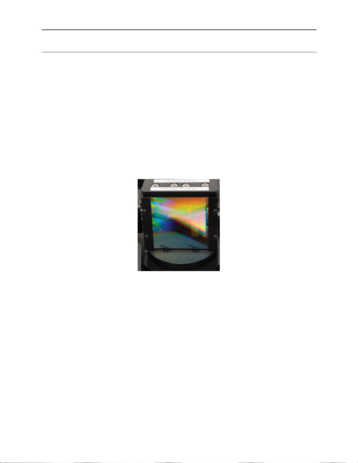
11.5 49BGRATING INSTALLATION
Each grating comes mounted and aligned on a grating mount. For most applications, there is no
need to adjust this grating holder. Refer to the general warnings and precautions section of this
manual regarding the care and handling of diffraction gratings. Note that only one grating should
be replaced at a time.
Procedure:
1. Using the Cornerstone Hand Controller or utility software, close the shutter.
2. Command the Cornerstone to go to the grating that is to be replaced.
3. Go to wavelength 0. The grating facing the collimating mirror is the grating that was selected.
4. Turn off the power switch on the monochromator and unplug the instrument from the
electrical mains.
5. Remove all screws holding the monochromator cover in place, then remove the cover.
6. Two long screws, one on each side of the grating, must be removed. Used a screwdriver to
loosen these screws.
7. Grasp the sides of the grating mount with one hand and firmly pull the grating up and out of
the instrument. Pull in a direction parallel to the grating face – not directly upwards. During
this process, ensure the other grating does not move. It should be held in place using a free
hand by grasping or pressing down on the grating holder.
8. Carefully uncover the new grating to be installed and set aside.
9. Use the cover from the new grating to protect the grating that was just removed.
10. Install the new grating onto the grating platform and ensure the new grating is parallel to the
other grating. The grating should fit into a pin located on the platform.
11. Push the new grating up against the large central pin in the middle of the platform.
12. Re-install the long screws that held the previous grating in place. Use only firm finger
pressure to tighten them. Do not tighten one completely while the other screw is loose. It is
best to alternate tightening between the two screws. Ensure the screws line up parallel with
the grating face.
13. Replace the cover on the monochromator and secure using all screws provided. Failure to
use all hardware will result in increased stray light.
14. Connect the monochromator to the electrical mains and switch on the power.
15. Follow the procedures outlined in this manual to determine the grating factor and any offset.
16. Use the Mono utility software to update the calibration parameters as needed.
17. It is suggested to verify the calibration factors and offsets of the other gratings that were not
replaced, as they may have accidentally been moved during this process.
Page 39

90088262 MCS130B
CORNERSTONE 130B MONOCHROMATORS
39
Figure 27: Grating Platform without Gratings
Figure 28: Grating Platform with Gratings Installed
Page 40

90088262 MCS130B
CORNERSTONE 130B MONOCHROMATORS
40
12 11BTROUBLESHOOTING
This section suggests solutions to potential issues that may be encountered when operating the
Cornerstone monochromator. If the tips in this section do not restore the instrument to working condition,
contact Newport to arrange for technical support or repair. Contact information can be found in the
Warranty and Service section of this user’s manual.
12.1 50BCORRUPTED MEMORY
The monochromator comes with calibration parameters, which are stored in a file on the memory
stick shipped with the instrument. If these parameters were corrupted from, possibly, performing
an incorrect field calibration, they will need to be reset. Other possible causes include electrostatic
discharge or other high field radiation near or in contact with the instrument.
The instrument parameters need to be reloaded from the calibration parameter sheet. Use the
utility program and select the first grating. Update the parameters for this grating. Then go to the
second grating and also update these parameters.
Figure 29: Entering Calibration Values in Utility Software
Page 41

90088262 MCS130B
CORNERSTONE 130B MONOCHROMATORS
41
13 12BSPECIFICATIONS
General Specifications
Focal Length
130 mm
F/#
F/3.9
Wavelength Selection Method
Motorized
Usable Wavelength Range
280 to 2500 nm, grating dependent
Spectral Resolution
Grating dispersion and slit width dependent
Wavelength Accuracy
+/- 0.25 nm
Wavelength Precision
+/- 0.075 nm
Stray Light
0.03%
Ports
1 input port, 1 output port
Shutter Control
Software, Hand Controller, low-level commands
Shutter minimum exposure
0.3 s
Shutter maximum repetition
2.0 Hz
Wavelength Scan Speed
3 nm/s at 1 nm step rate; 24 nm/s at 10 nm step rate
Motorized Filter Wheel
Models USFW-100, 74010, Apex2 filter wheel
Utility Software Requirements
Windows 10 and MAC OS-X (Windows XP compatible
software also available)
TracQ Basic Software
Compatible
Yes
74009 Hand Controller
Compatible
Yes
Voltage
100-240 VAC, 47-63 Hz
Weight
12 lb [5.4 kg]
Micrometer Adjustable Slit Specifications
Width Range
4 μm to 3 mm
Height Range
3 mm to 12 mm
Repeatability
± 10 μm
Accuracy
± 10 μm (width from 4 μm to 250 um)
± 5% (width from 250 μm to 3 mm)
Wavelength Accuracy:
The capability of the monochromator to output the desired wavelength.
Wavelength Precision:
The ability of a wavelength to be consistently reproduced and the number of
significant digits to which it has been reliably measured.
Page 42

90088262 MCS130B
CORNERSTONE 130B MONOCHROMATORS
42
14 13BDIMENSIONS
Figure 30: Cornerstone 130B Dimensions
Page 43

90088262 MCS130B
CORNERSTONE 130B MONOCHROMATORS
43
Figure 31: 74001 Micrometer Adjustable Slit Dimensions
Figure 32: 77294 Fixed Slit Dimensions
Page 44

90088262 MCS130B
CORNERSTONE 130B MONOCHROMATORS
44
Figure 33: Model 74006 Mounting Plate
Page 45

90088262 MCS130B
CORNERSTONE 130B MONOCHROMATORS
45
15 1APPENDIX I: REMOTE COMMANDS AND QUERIES
15.1 OPENING RS-232 COMMUNICATION INTERFACE
The CS130B’s USB port implements the USB Test and Measurement class (USBTMC), making i t
directly compatible with National Instruments’ LabVIEW programming system. It provides a robust
way to send messages to the CS130B. However, RS232 continues to be an extremely simple
communications bus, once it is configured correctly.
Commands and Queries may be sent to the CS130B’s RS-232 port using HyperTerminal, PuTTY,
YAT, Newport’s MonoTerm, or other similar terminal-emulation programs. Connect a standard 9-
pin PC serial port to the CS130B using a straight-through (not null modem) cable. Once the
terminal program is open and running, select the connected COM port and configure it according
to the following settings:
Baud Rate:
9600
Data Bits:
8
Parity:
None
Stop Bits:
1
Flow Control:
None
The CS130B requires all Statements to be terminated by a carriage return followed by a linefeed.
Configure the terminal emulator to send a carriage return and line feed (CR-LF) as its terminator1.
All responses from the CS130B end with a carriage return followed by a linefeed.
When shipped from the factory, the CS130B echoes each RS-232 character as it receives it. This
feature can be turned off or on using the “Echo” command (see the Command Reference). The
echo can be handy when troubleshooting a serial connection, but it may be troublesome when
developing a test program.
Note: the RS-232, USB, and Hand Controller ports are all active at all times. There are times when
this can be useful but it’s important to recognize the possibility that commands rec ei ved on o ne
port could override those from another.
1
Some terminal emulators call the terminator the “EOL (end of line) sequence”.
Page 46

90088262 MCS130B
CORNERSTONE 130B MONOCHROMATORS
46
15.2 TROUBLESHOOTING RS-232
One of the most common problems when first connecting a PC to an RS-232 device is that the
cable may swap the signals. The cable should be the straight-through type, and if you aren’t sure
that it is, there are a couple of things you can try.
The simplest is to connect an ohmmeter between pin 3 on the PC end of the cable and pin 3 on
the device end. There should be no resistance between them. The same goes for pin 2. And just
to be sure, also check pin 5: sometimes there is a break in the cable.
The nomenclature for RS-232 has suffered a great deal of re-naming and the “standard” has
become non-standard, but most PCs now transmit signals on pin 3 of their DB-9 connector, and
receive signals from pin 2. The Transmit signal (Tx) is held at roughly -9V (the actual voltage
depends on the PC) when not transmitting, and the Receive signal (Rx) is floating. So another
troubleshooting method is to first connect one end of the cable to the PC, and connect a
voltmeter between pins 3 and 5 on the other end. You should see some negative voltage
between pin 3 and pin 5, and close to 0V between pin 2 and pin 5.
The CS130B receives on pin 3 (device Rx) and transmits on pin 2 (device Tx). The PC transmits
to the CS130B’s Receive pin, and receives from the CS130B’s Transmit pin.
The CS130B implements two RS232 communications modes that may be useful when problems
arise. They are “echo” and “handshake”. See the following sections for more information about
them.
One of the most useful tools is called a “sniffer”. It monitors and displays traffic on the transmit
and receive lines so that you can verify that the PC is sending what you want it to, and examine
what the device is sending. The EZ-Tap from Stratus Engineering is a good example.
The “activity” LED on the CS130B panel blinks rapidly when the CS130B receives a command on
the RS232 or USB. This is the small light in the lower right corner of the panel. It normally blinks
at a 1 Hz rate to show that the unit is powered up and ready. It blinks quickly when the grating or
filter wheel are moving, or when a command is received on the USB or RS232 port. Make sure it
blinks quickly a couple of times when you send a command.
DB-9 connector at end of cable, other end connected to PC.
6
5
1
9
V from pin 3 (PC Tx) to pin 5 (gnd) ~ -9V
Page 47

90088262 MCS130B
CORNERSTONE 130B MONOCHROMATORS
47
15.3 COMMAND AND QUERY SYNTAX
For the purposes of this discussion, communication with the instrument is divided into two types.
Messages sent to the CS130B from the computer are called “Statements”, and messages received
by the computer from the monochromator are called “Responses”. When communicating with the
instrument, two types of Statements are used: “Commands” and “Queries”. A Command c auses
some physical action or sets an internal parameter. A Query asks a question of the instrument,
which returns a Response. Fundamentally, the syntax is the same for all messages.
Termination
Responses from the CS130B end with a carriage return (ASCII character code 13 decimal) and
linefeed (ASCII character code 10 decimal). The Detailed Command Reference in this Appendix
does not show the termination characters.
Capitalization
Statements may be sent in upper case, lower case, or in any combination of the two.
Parameters
Some Statements require a parameter, separated from the command by at least one space.
Numeric parameters can be strings representing either integers or floating point numbers. Some
commands accept alphabetic strings.
15.4 STANDARD MODE
Most communication with the CS130B, especially within customers’ application software, uses
Standard mode (as opposed to Handshake mode).
In Standard mode the CS130B does not send the status byte after general Statements as in
Handshake mode. To select Standard mode, send the command “Handshake 0”.
In Standard mode, statements are handled as follows:
Commands
If Echo is turned on, the CS130B echoes back all characters it receives on the RS232 port. Thus,
after sending a Command, an application must read back the echoed command. There is no
further response to a Command. Note: Statements received on the USB port are never echoed.
Example (RS-232, echo on):
Send: GOWAVE 500[cr][lf] Response: GOWAVE 500[cr][lf]
Example (RS-232, echo off):
Send: GOWAVE 500[cr][lf] Response: (none)
For commands received on the USB port, the CS130B sends no echo and no other response to a
command.
Example (USB):
Send: GOWAVE 500[cr][lf] Response: (none)
Page 48

90088262 MCS130B
CORNERSTONE 130B MONOCHROMATORS
48
Queries
If Echo is enabled, the CS130B echoes back all characters it receives on the RS232 port.
Additionally, it sends the response to the query. After sending a Query, the application must read
back both the echo and the answer.
Example (RS-232, echo on):
Send : WAVE?[cr][lf] Response: WAVE?[cr][lf]500.01[cr][lf]
Example (RS-232, echo off):
Send : WAVE?[cr][lf] Response: 500.01[cr][lf]
For queries received on the USB port, the CS130B sends only the query response. The query
response can be read back by itself.
Example (USB):
Send : WAVE?[cr][lf] Response: 500.01[cr][lf]
Page 49

90088262 MCS130B
CORNERSTONE 130B MONOCHROMATORS
49
15.5 HANDSHAKE MODE
In Handshake mode the CS130B sends a status byte after every Statement it receives on the
RS232 bus. For queries, the CS130B sends the status byte after the response. This mode may be
useful when developing an application using RS232 or when troubleshooting RS232
communication problems. Use the command: “HANDSHAKE 1” to put the CS130B into
Handshake mode. Handshake mode does not apply to USB.
In Handshake mode, Statements received on the RS232 port are handled as follows:
Commands
If Echo is enabled, the CS130B echoes every character it receives on the RS-232 port. In
Handshake mode the CS130B also reports the status byte after the command is received. Thus,
after sending a command with both Echo and Handshake enabled, the customer’s application
must read back both the echoed statement and the status byte.
Example (RS-232, echo on):
Send: GOWAVE 500[cr][lf] Response: GOWAVE 500[cr][lf]00[cr][lf]
Example (RS-232, echo off):
Send: GOWAVE 500[cr][lf] Response: 00[cr][lf]
For commands received on the USB port, the CS130B sends no echo and no other response to a
command.
Example (USB):
Send: GOWAVE 500[cr][lf] Response: (none)
Queries
If Echo is enabled, the CS130B echoes every character it receives on the RS-232 port.
Additionally, it sends a Response to that query. With Handshake enabled, the CS130B also sends
the status byte. After sending a Query with Echo and Handshake enabled, the customer’s
application must read back a three-part answer: the echo, the Response, and the status byte.
Example (RS-232, echo on, handshake on):
Send : WAVE?[cr][lf] Response: WAVE?[cr][lf]500.01[cr][lf]00[cr][lf]
Example (RS-232, echo off, handshake on):
Send : WAVE?[cr][lf] Response: 500.01[cr][lf]00[cr][lf]
For queries received on the USB port, the CS130B sends only the query response. The query
response can be read back by itself.
Example (USB):
Send : WAVE?[cr][lf] Response: 500.01[cr][lf]
Discussion
In general, Handshake and Echo are only useful when troubleshooting an RS232 connection.
Otherwise they require an application to collect a significant amount of unused information.
Also, when first getting familiar with the command set, it is useful to send the “system:error?” query
after each Statement to make sure the spelling and parameter types are correct: see the “Error
Codes” section in this appendix.
Page 50

90088262 MCS130B
CORNERSTONE 130B MONOCHROMATORS
50
15.6 CS130B COMMAND QUICK REFERENCE SUMMARY
Command
OVL/SEQ
Query
Hand Controller Key
CALIBRATE [value]
SEQ
SHIFT CALIB
ECHO [0/1]
SEQ
ECHO?
ERROR?
FILTER [f]
OVL
FILTER?
FILTER
FILTER[f]LABEL [text]
SEQ
FILTER[f]LABEL?
SHIFT LABEL | FILTER
FINDHOME
OVL
GOWAVE [value]
OVL
GOWAVE?
GO WAVE
GRAT [g]
OVL
GRAT?
GRAT
GRAT[g]FACTOR [value]
OVL
GRAT[g]FACTOR?
GRAT[g]LABEL [text]
SEQ
GRAT[g]LABEL?
SHIFT LABEL | GRAT
GRAT[g]LINES [value]
OVL
GRAT[g]LINES?
LINES
GRAT[g]OFFSET [value]
OVL
GRAT[g]OFFSET?
HANDSHAKE [0/1]
SEQ
HANDSHAKE?
INFO?
SHUTTER [O/C]
OVL
SHUTTER?
SHUTTER
STB?
SLOWSTEP [value]
OVL
STEP [value]
OVL
STEP UP/DOWN,
SHIFT STEP UP/DOWN
STEP?
STEPSIZE [value]
SEQ
STEPSIZE?
UNITS [text]
SEQ
UNITS?
SHIFT UNITS
VERSION?
WAVE?
In this table, replace the notation [f] with the desired filter number, [g] with the desired grating number,
and [s] with the desired slit number. The column labeled “OVL/SEQ” indicates whether the command is
overlapped or sequential: see the “Command Synchronization” section. All queries are sequential.
In addition to the commands that were carried over from the CS130, the CS130B has these new ones:
Command
OVL/SEQ
Query
Hand Controller Key
*OPC
SEQ
*ESR?
*IDN?
*OPC?
*WAI
IDLE?
LOCATION
OVL
LOCATION?
SYSTEM:ERROR?
Page 51

90088262 MCS130B
CORNERSTONE 130B MONOCHROMATORS
51
15.7 DETAILED COMMAND REFERENCE
This section describes the syntax, parameters, and functionality for every CS130B Statement.
Some Statements appear with some upper-case and some lower-case letters. For example,
“GRATing” indicates that the CS130B will accept either the command “grat” or “grating”. The
lower-case characters are optional, but if any of them are sent, they all must be sent: in this case
“gratin” is not allowed.
CS130B Commands
Command:
CALIBRATE
Purpose:
Make a minor offset adjustment to the wavelength calibration. Use when
installing new gratings, or at any point when the wavelength calibration is
disrupted. Send this command to define the current position as the
wavelength specified in the parameter. Calculates a new offset for the
grating and saves it accordingly. A calibration procedure is outlined
elsewhere in this manual.
Parameter:
The actual wavelength at the output.
Example:
calibrate 587.1 : assuming the units are microns, change the calibration so
that the current grating location corresponds to 587.1 microns.
Command:
ECHO
Purpose:
Tell the CS130B to send back every character it receives on the RS232
port.
Parameter:
1 to turn on echo, 0 to turn off.
Example:
Echo 0 : turn off echo.
Note:
For reverse compatibility, the “info?” query temporarily enables echo mode.
Command:
ECHO?
Purpose:
Query the echo setting.
Example:
echo?
E.g. response:
1: indicates echo is turned on.
Command:
ERROR?
Purpose:
Query the error byte. Note: see also the “system:error” query.
Example:
error?
E.g. response:
1: indicates a command was unrecognized. See the Error Codes
section, later in this appendix.
Note:
This query is included for reverse compatibility with the older Cornerstone
models. The preferred error query is “system:error?”
Page 52

90088262 MCS130B
CORNERSTONE 130B MONOCHROMATORS
52
Command:
FILTER
Purpose:
Move the filter wheel to a desired filter.
Parameter:
An integer number from 1 to 6.
Example:
filter 2: rotate the wheel to filter 2.
Default:
1
Command:
FILTER?
Purpose:
Query the current filter wheel position. This may be different from the
filter setting since it is possible to rotate the wheel manually.
Example:
Filter?:
E.g. response:
5: indicates the filter wheel is at location 5.
E.g. response:
0: indicates the filter wheel position is unknown, probably because the
wheel is between filters. The CS130B will move the wheel to the
selected filter.
Command:
FILTER:SET?
Purpose:
Query the current filter wheel position setting.
Example:
Filter:set?:
E.g. response:
4: indicates filter 4 is the current selection.
Command:
FILTER1LABEL
Purpose:
Set a label for filter 1.
Parameter:
An unquoted string up to 8 characters in length.
Example:
Filter1label green: set filter 1’s label to the word “green”.
Example:
Filter1label 550nm: set filter 1’s label to the word “550nm”.
Default:
“ “ (spaces).
Command:
FILTER1LABEL?
Purpose:
Query the label for filter 1.
Example:
Filter1label?
E.g. response:
555nm: indicates the label has been set to “555nm”.
The labels for the other five filters are set and queried by replacing the number “1” in the above
command and query with the filter number of interest.
Command:
FINDHOME
Purpose:
Cause the grating rotation stage to rotate to its mechanical “home”
position.
Example:
findhome
Page 53

90088262 MCS130B
CORNERSTONE 130B MONOCHROMATORS
53
Command:
GOWAVE
Purpose:
Store the wavelength setting and rotate the currently-selected grating
to the angle that causes the specified wavelength to appear at the
output.
Parameter:
A floating-point number representing the desired wavelength in the
currently-selected wavelength units.
Example:
gowave 877.679: rotates the grating to the 877.679nm location
(assuming units are nm).
Example:
gowave 546: rotates the grating to the 546nm location (assuming units
are nm).
Default:
0.
Command:
GOWAVE?
Purpose:
Query the current wavelength setting. Also see the “wave?” query,
which queries the actual wavelength.
Example:
gowave?
E.g. response
756.9087: the wavelength has been set to 756.9087.
Page 54

90088262 MCS130B
CORNERSTONE 130B MONOCHROMATORS
54
Command:
GRATing
Purpose:
Store the grating setting and rotate the grating stage to the desired
grating (if it’s different from the current grating). The stage will rotate to
the location required for the new grating to pass the currently-selected
wavelength to the output.
Parameter:
A decimal number from 1 to 2.
Example:
grating 2: if the current grating is not 2, rotate the grating stage to
grating 2.
Default:
1
Command:
GRATing?
Purpose:
Query the current grating setting.
Example:
grating?
Example:
grat?
E.g. response
1: the currently-selected grating is number 1.
Command:
GRAT1FACTOR
Purpose:
Set the calibration multiplier for grating 1.
Parameter:
A floating-point number.
Example:
Grat1factor 1.1: set the cal factor for grating 1 to 1.1.
Example:
grat1factor 1: set the cal factor for grating 1 to 1.0.
Default:
1.0.
Command:
GRAT1FACTOR?
Purpose:
Query the calibration multiplier for grating 1.
Example:
grat1factor?
E.g. response
0.99: the cal factor is 0.99.
Command:
GRAT1LABEL
Purpose:
Set a label for grating 1.
Parameter:
An unquoted string up to 8 characters in length.
Example:
grat1label blz800: set the label for grating 1 to “blz800”.
Default:
“ ” (spaces).
Command:
GRAT1LABEL?
Purpose:
Query grating 1’s label.
Example:
grat1label?
E.g. response
Hitone: the label has been set to the string “Hitone”.
Page 55

90088262 MCS130B
CORNERSTONE 130B MONOCHROMATORS
55
Command:
GRAT1LINES
Purpose:
Set the line spacing for grating 1 in lines per mm.
Parameter:
An integer number from 0 (mirror) to 4000.
Example:
grat1lines 600: set the lines/mm for grating 1 to 600.
Default:
600.
Command:
GRAT1LINES?
Purpose:
Query grating 1’s line spacing setting.
Example:
grat1lines?
E.g. response
1200: the number of lines per mm for grating 1 has been set to 1200.
Command:
GRAT1OFFSET
Purpose:
Set the calibration offset for grating 1.
Parameter:
A floating point number.
Example:
grat1offset -2.1: set the cal offset for grating 1 to -2.1.
Default:
0.0.
Command:
GRAT1OFFSET?
Purpose:
Query grating 1’s line calibration offset setting.
Example:
grat1offset?
E.g. response
1.5: the cal offset for grating 1 has been set to 1.5.
To set the settings for the other gratings using the previous grat1nnn commands, replace the
number “1” with the desired grating number.
Command:
HANDSHAKE
Purpose:
Set the handshake setting. See the “Handshake Mode” section.
Parameter:
0 to turn off handshake, 1 to turn on.
Example:
handshake 1: turn on handshake mode
Default:
0 (disabled)
Command:
HANDSHAKE?
Purpose:
Query the handshake setting.
Example:
Handshake?
E.g. response
1: handshake mode is turned on
Page 56

90088262 MCS130B
CORNERSTONE 130B MONOCHROMATORS
56
Command:
IDLE?
Purpose:
See if any operations are pending. See the section entitled “Command
Synchronization”.
Example:
IDLE?
E.g. response
1: no operations are pending.
E.g. response
0: an operation is pending.
Command:
INFO?
Purpose:
Query for basic instrument information. The response is:
“Oriel Instruments, Model 74000 Cornerstone 130,SNXXX,V.VV”
where XXX is the unit's serial number and V.VV is the version number
for the internal firmware. This information is displayed on the Hand
Controller for 2 seconds when the unit is powered up. This command is
included for reverse compatibility: the “*IDN?” query is preferred.
Note:
This query enables Echo mode until the next power cycle.
Page 57

90088262 MCS130B
CORNERSTONE 130B MONOCHROMATORS
57
Command:
SHUTTER
Purpose:
Open or close the shutter on the input port.
Parameter:
1 or the character ‘O’ to open the shutter, 0 (zero) or ‘C’ to close.
Example:
shutter 1: open the shutter.
Example:
shutter c: close the shutter.
Default:
0 (closed).
Command:
SHUTTER?
Purpose:
Query the shutter setting. Response is ‘O’ or ‘C’.
Example:
shutter?
E.g. response
C: the shutter is closed.
Command:
STB?
Purpose:
Query the Cornerstone status. A value of 0 represents no error, and 32
indicates an error occurred since the last “STB?” query. This query
clears the status byte.
Example:
STB?
E.g. response
0: no error detected.
E.g. response
32: an error was detected.
Page 58

90088262 MCS130B
CORNERSTONE 130B MONOCHROMATORS
58
Command:
SLOWSTEP
Purpose:
Slowly step the grating rotation stage a desired number of steps.
Parameter:
The number of steps to take. The allowed range is -10000 to 10000. If
no parameter is given, the value previously specified by the “stepsize”
command is used.
Example:
slowstep 1050: slowly step the stage 1050 steps clockwise.
Example:
slowstep -50: slowly step the stage 50 steps counterclockwise.
Note:
The time between steps is approximately 10 msec.
Command:
STEP
Purpose:
Rapidly step the grating rotation stage a desired number of steps.
Parameter:
The number of steps to take, in the range -10000 to 10000. If no
parameter is given the value specified by the “stepsize” command is
used.
Example:
step 10000: quickly step the stage 10000 steps clockwise.
Example:
step -500: quickly step the stage 500 steps counterclockwise.
Command:
STEPSIZE
Purpose:
Set the number of steps to take when a “step” or “slowstep” command
is received.
Parameter:
The number of steps to take, in the range -10000 to10000.
Example:
stepsize 10: set the step size to 10 steps.
Default:
1 step.
Command:
STEPSIZE?
Purpose:
Query the step size setting.
Example:
stepsize?
E.g. response:
20: the step size has been set to 20.
Command:
SYSTem:ERRor?
Purpose:
See what error has occurred, if any. The response to this query is a
string containing an error code number and an error description. See
the Error Codes section in this Appendix for explanation and examples.
Example:
syst:err?
E.g. response:
-224, Illegal Parameter Value: the CS130B received a command with
a bad parameter value.
Example:
system:err?
E.g. response:
403, Cannot Reach Wavelength: the CS130B can’t achieve the
desired wavelength using the current grating.
Page 59

90088262 MCS130B
CORNERSTONE 130B MONOCHROMATORS
59
Command:
UNITS
Purpose:
Specify wavelength units. Wavelength values will be displayed,
reported and accepted in these units.
Example:
units nm: set wavelength units to nanometers
Example:
units um: set wavelength units to microns
Example:
units wn: set wavelength units to wave number (cm-1)
Default:
nm
Command:
UNITS?
Purpose:
Query wavelength units.
Example:
units?
E.g. response:
um: units are microns
Command:
VERSION?
Purpose:
Query the CS130B firmware version.
Example:
version?
E.g. response:
2.01: version is 2.01
Command:
WAVE?
Purpose:
Query the wavelength corresponding to the actual position of the
grating rotation stage. This may be slightly different from the
wavelength setting, since the rotation stage has a finite number of
allowable positions.
Example:
wave?
E.g. response:
444.003506: Actual wavelength is slightly different from 444nm setting.
Page 60

90088262 MCS130B
CORNERSTONE 130B MONOCHROMATORS
60
Command:
*IDN?
Purpose:
Query the CS130B’s identification information. The comma-separated
fields in the response are:
Manufacturer ID, instrument, serial number, and firmware version.
Example:
*IDN?
E.g. response:
Newport Corp, CS130B,1234,2.01
Command:
*ESR?
Purpose:
Query the contents of the ESR register.
See the section entitled “synchronizing commands”.
Example:
*ESR?
E.g. response:
0: indicates the value in the ESR is 0.
Command:
*OPC
Purpose:
Instruct the CS130B to set bit 0 in the ESR when all operations are
complete. See the section in this Appendix entitled “Command
Synchronization”.
Example:
*OPC
Command:
*OPC?
Purpose:
The CS130B will respond with the value ‘1’ when all operations are
complete. See the section in this Appendix entitled “Command
Synchronization”.
Example:
*OPC?
Note:
This query may take some time to respond, especially if several
wavelength or filter operations have been initiated.
Command:
*WAI
Purpose:
Instruct the CS130B to buffer subsequent commands and queries until
all pending operations are complete, and then handle them. See the
section in this Appendix entitled “Command Synchronization”.
Example:
gowave 456.5;*wai;shutter o
Note:
This command does not affect pending operations or the reception of
commands.
Page 61

90088262 MCS130B
CORNERSTONE 130B MONOCHROMATORS
61
15.8 COMMAND SYNCHRONIZATION
The CS130B has commands that allow an application to coordinate some of its operations. For
example, an application may need to wait for the grating rotation stage to reach a wavelength
before it begins to read a detector. The pseudo-code for this would be:
• Send wavelength command;
• Wait for wavelength operation (stage rotation) to finish;
• Read detector.
Sequential versus Overlapped Commands
The CS130B can accept and buffer more than one command. It completes “sequential” commands
before starting on the next command in its command queue. In contrast, it handles “overlapped”
commands by initiating the appropriate operation and then starting on the next command (if any)
while the previous overlapped operation is in progress.
The wavelength command is an example of an overlapped operation. It may take some time to
move the grating to a new wavelength, so the CS130B initiates the move operation and then starts
the next command.
The CS130B provides four methods to facilitate finding out when overlapped operations have
finished. Some of these methods are adapted from the IEEE488 standard. The simplest to use is
the “*OPC?” query. The CS130B does not send a response to this IEEE488-standard query until
all of its pending operations are complete, and then it returns the value 1. An application can send
this query and wait until it receives a response; then it will know that all pending operations are
complete. For example:
• Send wavelength command (e.g. gowave 585);
• Send “*opc?” and wait for response;
• Read detector.
If an operation or a series of operations takes a long time to complete, the application may
encounter a situation where its “query” mechanism times out before the CS130B finishes the
requested operations and responds to “*OPC?”. If increasing the application’s timeout is not an
option, or if the application simply cannot afford to halt while it waits for a response, there are other
approaches that allow the application to poll the CS130B.
The second approach uses the “idle?” query. It returns the value “1” when all operations are
complete, and “0” when there is at least one operation pending. An application may periodically
send this query to poll the CS130B for operation complete. Pseudo-code for this approach would
be:
• Send wavelength command;
• Send “idle?” query.
• If response is “0”, continue sending “idle?” query until response is “1”.
• Read detector.
The third approach, as specified in IEEE488, is more complicated. The idea is to tell the CS130B
to set bit 0 in its Event Status Register (ESR) when all operations are complete. The application
can then periodically poll the ESR until bit 0 is set. Here is some pseudo-code for that:
• Send wavelength command (this initiates the wavelength operation);
• Send *OPC command (tells CS130B to set bit 0 when all currently pending operations
are finished);
• Read Event Status Register (use *ESR? query); if bit 0 is not set, read it again. Continue
until bit 0 is set.
• Read detector.
Page 62

90088262 MCS130B
CORNERSTONE 130B MONOCHROMATORS
62
The fourth synchronization operation, also adopted from IEEE488, is only for synchronizing
CS130B internal operations. The *WAI command tells the CS130B to store and not process any
further commands until all currently pending operations are finished. In essence, when it follows an
overlapped command, the *WAI command makes the overlapped command sequential.
It doesn’t necessarily help with synchronizing a separate instrument with the CS130B, but it can be
used for example to set a wavelength, wait for the wavelength to settle, then open the shutter:
• Send wavelength command (e.g. “gowave 587.1”);
• Send *wai command;
• Send shutter command (e.g. “shutter o”).
The *WAI command may be more useful for instruments that can perform operations that are
dissimilar, for example, a meter that can measure current or voltage.
It should be noted that incoming commands are queued in the input buffer while the CS130B is
waiting. This buffer can store up to about 20 commands.
15.9 ERROR CODES
The Status Byte is cleared to 0 at power-up. Whenever any error is encountered it is set to the
value 32. It is cleared again when the CS130B receives a “STB?” query.
The Error Code is set to a value that corresponds to the latest error. Query it using the “ERROR?”
query. The CS130B sends the value of the Error Code and then resets the value to 0.
Error code Cause
0 No error.
1 Command not understood.
2 Bad parameter used in command.
3 Destination position for wavelength motion not allowed.
6 Accessory not present (usually filter wheel).
8 Could not home wavelength drive.
9 Label too long (e.g. “filter1label chartreuse”).
10 System error.
The Error Code is included for reverse compatibility with older Cornerstone products. The
preferred error-detect query is “system:error?”. When the CS130B encounters an error, it places
an error code and an error description in a queue. Up to ten errors can be stored in the queue.
Only one error is reported at a time, even though there may be several in the queue. To read all
the errors, send the “system:error?” query until the response is “0, No Error”.
The CS130B responds to the “system:error?” query by sending a string cont aining two c omma -
separated fields. The first field is a decimal number representing the code for the oldest error. The
second field is a string containing a short description of the error. Here are some examples of error
responses. The full list is on the next page.
Command
Response to “system:error?” query
Explanation
gowav 765
-113, Undefined Header
CS130B doesn’t understand
“gowav” (should be “gowave”)
gowave 9999
-224, Illegal Parameter Value
Requested wavelength too high
gowave 765
0, No Error
No problem
N/A
501, Filter Wheel Missing
No filter wheel detected at power-up.
Page 63

90088262 MCS130B
CORNERSTONE 130B MONOCHROMATORS
63
Here is the list of the error codes and strings that the CS130B can detect and report. Note that
some codes are positive and some are negative.
Error Code
String
Explanation
-104
Data Type Error
Parameter in command has an incorrect
character.
-108
Parameter Not Allowed
Not all commands can take a parameter.
-109
Missing Parameter
Some commands require a parameter.
-113
Undefined Header
CS130B could not find the requested command.
-115
Unexpected Number of
Parameters
The command included too many or too few
parameters.
-150
String Data Error
A parameter that should be a string had
something wrong with it; perhaps too long.
-151
Invalid String Data
Parameter string not understood. E.g., “units
golly”.
-185
Label Too Long
Filter and Grating labels can’t be longer than 8
chars.
-186
Cmd Queue Overflow
Too many commands have been queued.
-187
Cmd Too Long
Command string too long (max 64 characters).
-220
Parameter Error
General parameter error e.g. “shutter 7”
-222
Data Out Of Range
Numeric parameter value too large to store.
-224
Illegal Parameter Value
Parameter value can’t be realized, e.g. “gowave
99999”
-320
Storage Fault
Error detected in non-volatile storage, e.g. cal
data or stored settings. This error is rare and is
usually cleared by cycling power.
-340
Calibration Failed
User calibration encountered a problem.
-341
Calibration Data Invalid
Something wrong with calibration parameter.
-350
Error Queue Overflow
More than 10 errors have been detected.
-351
Serial Num Truncated
The serial number was too long.
-420
Query Unterminated
Unit was asked to respond but no response is
available. Likely cause: unrecognized query,
e.g. “shuter?”.
402
Unable to Home Grating
Hardware failure: grating motor unable to home.
403
Cannot Reach
Wavelength
Typically when grating-change command results
in unobtainable wavelength.
404
Grating Halted
Caused by grating or wavelength command
during firmware upgrade.
501
Filter Wheel Missing
Filter wheel not detected at power-up.
Page 64

90088262 MCS130B
CORNERSTONE 130B MONOCHROMATORS
64
502
Filter Wheel Fault
Hardware failure: filter wheel not operating
properly.
504
Filter Halted
Filter command during firmware upgrade.
Page 65

90088262 MCS130B
CORNERSTONE 130B MONOCHROMATORS
65
16 15BAPPENDIX II: HAND CONTROLLER COMMANDS
The optional 74009 Hand Controller is designed specifically for use with Oriel’s Cornerstone series
monochromators and MS260i spectrographs. It is very easy to set up – simply plug it into the instrument
and it’s ready to go. There is no need to purchase a computer and set up software. The Hand Controller
is a convenient option in locations where security is an issue.
There is no need to memorize commands or key sequences. The 24 keys are clearly labeled with
functions like “Shutter”, “Go Wave” and “Filter”. The display provides information about the grating
selection, grating line density, active filter position, current wavelength, and shutter status. Using the
Hand Controller provides access to nearly all the functionality of the monochromators and spectrographs.
It comes with a 14-foot [4.3 meter] long cable.
16.1 58BACTIVATING THE HAND CONTROLLER
With the Hand Controller connected, turn on power to the Cornerstone. Some CS130B system
information is briefly displayed including serial number and firmware version. Press the LOCAL
key to activate communications through the Hand Controller.
16.2 59BUSING THE KEYPAD
Some keys are divided into top and bottom halves. The function for the top half is called a “shifted”
function. To activate these commands press the SHIFT key in the bottom left corner and then
press the function key.
Many of the Cornerstone commands require a numeric parameter. First, press the function key for
the command. The bottom line of the display will then show an abbreviated form of the command.
Use the numeric keys to enter a new value. To execute the command press the ENTER key in the
bottom right corner.
While entering parameters, if you mistype one digit press SHIFT and then DEL (above the decimal
point in the numeric keypad); this will move backward one display position and delete that
character. Or, press the Abort key, or wait ten seconds, and the display will terminate the entry.
Figure 34: 74009 Hand Controller Keypad
Page 66

90088262 MCS130B
CORNERSTONE 130B MONOCHROMATORS
66
16.3 60BKEY REFERENCE
ABORT If you accidentally press a function key or enter a bad parameter you may press
the ABORT key to clear that command before it executes.
STEP DOWN Press this key once to move the Cornerstone to shorter wavelengths by the
smallest possible increment. Holding this key causes rapid single stepping
toward lower wavelengths. Press SHIFT and then STEP DOWN to define a
number of steps to move at once. Press ENTER to execute this larger move.
STEP UP Press this key once to move the Cornerstone to higher wavelengths by the
smallest possible increment. Holding this key causes rapid single stepping
toward higher wavelengths. Press SHIFT and then STEP UP to define a number
of steps to move at once. Press ENTER to execute this larger move.
GO WAVE This key moves the grating position to a specified output wavelength. Press GO
WAVE, then use the keypad to enter the desired wavelength, and finally press
ENTER to execute the move.
SLIT 1 This function is disabled on this model.
SHIFT SLIT 2 This function is disabled on this model.
SLIT 3 This function is disabled on this model.
SHIFT BAND This function is disabled on this model.
GRAT Press this key to move to another grating position. Press GRAT, then press
either 1 or 2 on the numeric keypad, and finally press ENTER to execute the
change. The display will update to show the correct parameters for the new
grating.
SHIFT LABEL This key (located directly above GRAT) provides access to the grating label.
The label is an eight-character alphanumeric field that is used for information
only. Newport assigns the grating blaze wavelength to the label during
calibration. However, you can use the keypad to type any number, then press
ENTER to accept that new value. The Hand Controller display only shows the
first four digits of the label.
LINES Press this key to change the lines/mm of the grating. This value is used for
wavelength calculations and will affect your calibration. This parameter should
be changed only when adding a new grating.
SHIFT CALIB This button is used to modify the wavelength calibration of the current grating.
Use the GO WAVE, STEP DOWN, and STEP UP keys until the light at the
output is at a known wavelength (often the intensity peak for a spectral
calibration lamp). If the wavelength shown in the top row of the display does not
match the known value, press SHIFT CALIB and use the numeric keypad to
Page 67

90088262 MCS130B
CORNERSTONE 130B MONOCHROMATORS
67
enter the known wavelength. Then press ENTER to change the calibration. The
current grating is thus calibrated (by applying an offset) over its entire range.
SHUTTER Open and close the shutter by pressing this button. The shutter position is
shown in the display as “OPN” for open and “CLS” for closed.
SHIFT PORT This function is disabled for this model.
FILTER Move the Filter Wheel accessory to the specified position. Press FILTER, then
type the number 1, 2, 3, 4, 5, or 6 indicating the desired position, then finally
press ENTER to execute the move.
SHIFT LABEL This key (located directly above FILTER) provides access to the filter label.
These labels are eight character alphanumeric fields, used for information only.
You can use the keypad to type any number, then press ENTER to accept that
new value. The Hand Controller display only shows the first four digits of the
label.
LOCAL Use this key to enable or disable communication through the Hand Controller.
SHIFT UNITS To change the wavelength units press this key, followed by either 1, 2, or 3 and
then press ENTER. The three number keys are labeled with the corresponding
units: 1 is nanometers (nm), 2 is micrometers (µm), and 3 is wave numbers
(cm-1) shown as “ν”.
SHIFT Press this key to enable the top half command of any applicable key.
SHIFT DEL Press this key to delete an entry.
ENTER Press this key to complete a command, where applicable and denoted above.
Page 68

90088262 MCS130B
CORNERSTONE 130B MONOCHROMATORS
68
17 16BAPPENDIX IV: GRATING PHYSICS TUTORIAL
17.1 61BTHE GRATING EQUATION
A typical diffraction grating consists of a substrate, usually of an “optical material”, with a large
number of parallel grooves ruled or replicated in its surface and overcoated with a reflecting
material such as aluminum. The quality and spacing of the grooves are crucial to the performance
of the grating, but the basic grating equation may be derived by supposing a section through the
grating surface, normal to the ruling direction as a sawtooth pattern, shown below.
Light rays A and B, of wavelength λ, incident on adjacent grooves at angle I to the grat i ng norm al
are shown. Consider light at angle D to the grating normal; this light originates from the A and B
rays as they strike the grating. The path difference between the A1 and B1 rays can be seen to be:
a sin I + a sin D.
Summing of the rays A1 and B1 results in constructive interference if the path difference is equal to
any integer multiple of the wavelength λ:
a(sin l+ sin D) = mλ
Where m = an integer, and is the order of diffraction
This is the basic grating equation. Note that if D is on the opposite side of the grating normal from I,
it is of the opposite sign.
We have considered only two grooves. Including all the other grooves does not change the basic
equation but sharpens the peak in the plot of diffracted intensity against angle D.
Figure 35: The Sawtooth Pattern of a Grating Section
Page 69

90088262 MCS130B
CORNERSTONE 130B MONOCHROMATORS
69
17.2 62BTHE GRATING EQUATION IN PRACTICE
When a parallel beam of monochromatic light is incident on a grating, the light is diffracted from the
grating in directions corresponding to m = -2, -1, 0, 1, 2, 3, etc. When a parallel beam of
polychromatic light is incident on a grating then the light is dispersed so that each wavelength
satisfies the grating equation. Positive orders have been eliminated from the illustration for clarity.
In most monochromators, the input slit and collimating mirror fix the direction of the input beam that
strikes the grating. The focusing mirror and exit slit fix the output direction. Only wavelengths that
satisfy the grating equation pass through the exit slit. The remainder of the light is scattered and
absorbed inside the monochromator. As the grating is rotated, the angles I and D change, although
the difference between them remains constant and is fixed by the geometry of the monochromator.
A more convenient form of the grating equation for use with monochromators is:
mλ = 2 x a x cos φ x sin θ
Where: φ = Half the included angle between the incident ray and the diffracted ray at the grating
θ = Grating angle relative to the zero order position
These terms are related to the incident angle I and diffracted angle D by:
I = θ + φ and D = θ - φ
Figure 36: The Grating Equation Satisfied for a Parallel Beam of Monochromatic Light
Figure 37: Polychromatic Light Diffracted From a Grating
Page 70

90088262 MCS130B
CORNERSTONE 130B MONOCHROMATORS
70
17.3 63BGRATING ORDER
It is important to note the sign of “m” is given by either form of the grating equation and can be
positive or negative. In a monochromator, the angles I and D are determined by the rotational
position of the grating. We use the sign convention that all angles that are counter clockwise from
the grating normal are positive, and all angles that are clockwise to the grating are negative. See
Fig. 4. The incident light, diffracted light and grating rotation can be at positive or negative angles
depending on which side of the grating normal they are. The half angle is always regarded as
positive.
If the angle D is equal to I and of opposite sign, then the grating angle and order are zero, and the
light is simply being reflected. If the grating angle is positive then the order is positive (m=1), if the
grating angle is negative, then the order is negative (m = -1). The half angle of the Cornerstone 130
is 5.1 and the orders are positive. With Oriel’s Cornerstone 260 monochromators, the half angle i s
11.83 and the orders are positive.
The grating equation is also satisfied for wavelengths in higher orders, when | m | is >1. Therefore
λ2 = λ1/2 for m = ±2, λ3 = λ1/3 for m = ±3, etc. The wavelength λ2 is in the second order and λ3 i s
in the third order, etc. Again, this concept is illustrated on the previous page.
Usually only the first order, positive or negative, is desired. The other wavelengths in higher orders
may need to be blocked. The input spectrum and detector sensitivity determine whether order
sorting or blocking filters are needed.
Figure 38: Sign Convention for the Angle of Incidence, Angle of Diffraction and Grating Angle
Page 71

90088262 MCS130B
CORNERSTONE 130B MONOCHROMATORS
71
17.4 64BGRATING DISPERSION
If we fix the angle I in the grating equation and differentiate with respect to wavelength we get:
a x cos D x δD = m x δλ
Thus:
δD/δλ is the angular dispersion or change of diffraction angle corresponding to a smal l change i n
wavelength. It is greater for smaller groove spacing, a (greater number of lines per millimeter);
larger orders, m; and larger diffraction angles, D.
The linear dispersion, δL/δλ, at a monochromator’s exit slit will vary with output focal length, f, and
angle D and is the product of the focal length and angular dispersion:
Normally, we use the “reciprocal linear dispersion”, which gives the wavelength dispersion in
nm/mm of slit width.
17.5 65BGRATING ILLUMINATION AND RESOLUTION
The resolving power R of a grating is defined in terms of wavelengths λ and λ + δλ, where λ + δλ is
the closest wavelength to λ that can be resolved. Theoretically:
Where:
δλ = Resolution
W = Illuminated width of the grating.
Normally the smallest slit available and optical aberrations, rather than the grating, determine the
attainable resolution. As an example, a monochromator (in this case Oriel’s MS257 model) is set to
λ = 500 nm, with a 1200 l/mm grating, R is 60000 with a fully illuminated grating. Based on this, δλ
is 0.008 nm. With 25 µm slits the product of slit width and reciprocal linear dispersion is 0.09 nm,
which is close to the measured value of 0.1 nm and R = 5000 instead of 60000.
If however, only a few mm of the grating are illuminated, as is sometimes the case with laser
sources incorrectly coupled to the monochromator, the grating resolution can broaden the
measured bandwidths. For example, if a laser illuminates only 2 mm of the grating width, the
measured bandwidth will be 0.2 nm, even for a very narrowband laser. Very short pulse (ps) lasers
will only illuminate a small portion of the grating at any instant. The resolution is degraded in
agreement with Heisenberg’s Uncertainty Principle.
If two monochromators are used in tandem then the reciprocal linear dispersion of the combination
is half that of a single monochromator.
Page 72

90088262 MCS130B
CORNERSTONE 130B MONOCHROMATORS
72
18 17BWARRANTY AND SERVICE
18.1 66BCONTACTING NEWPORT CORPORATION
Oriel Instruments belongs to Newport Corporation's family of brands. Thanks to a steadfast
commitment to quality, innovation, hard work and customer care, Newport is trusted the world over
as the complete source for all photonics and laser technology and equipment.
Founded in 1969, Newport-Oriel is a pioneering single-source solutions provider of laser and
photonics components to the leaders in scientific research, life and health sciences, photovoltaics,
microelectronics, industrial manufacturing and homeland security markets.
Newport Corporation proudly serves customers across Canada, Europe, Asia and the United
States through numerous international subsidiaries and sales offices worldwide. Every year, the
Newport Resource catalog is hailed as the premier sourcebook for those in need of advanced
technology products and services. It is available by mail request or through Newport's website.
The website is where one will find product updates, interactive demonstrations, specification charts
and more.
To obtain information regarding sales, technical support or factory service, United States and
Canadian customers should contact Newport Corporation directly.
Newport - Oriel Instruments
1791 Deere Avenue
Irvine, CA 92606 USA
Telephone: 800-222-6440 (toll-free in United States)
949-863-3144
Fax: 949-253-1680
Sales: oriel.sales@newport.com
Technical assistance: oriel.tech@newport.com
Repair Service: rma.service@newport.com
Customers outside of the United States must contact their regional representative for all sales,
technical support and service inquiries. A list of worldwide representatives can be found on the
following website: https://www.newport.com/contact/contactslocations
Page 73

90088262 MCS130B
CORNERSTONE 130B MONOCHROMATORS
73
18.2 67BREQUEST FOR ASSISTANCE / SERVICE
Please have the following information available when requesting assistance or service:
• Contact information for the owner of the product.
• Instrument model number (located on the product label).
• Product serial number and date of manufacture (located on the product label).
• Description of the problem.
To help Newport’s Technical Support Representatives diagnose the problem, please note the
following:
• Is the system used for manufacturing or research and development?
• What was the state of the system right before the problem?
• Had this problem occurred before? If so, when and how frequently?
• Can the system continue to operate with this problem, or is it non-operational?
• Were there any differences in the application or environment before the problem
occurred?
18.3 68BREPAIR SERVICE
This section contains information regarding factory service for this product. The user should not
attempt any maintenance or service of the system beyond the procedures outlined in this manual.
This product contains no user serviceable parts other than what is noted in this manual. Any
problem that cannot be resolved should be referred to Newport Corporation.
If the instrument needs to be returned for service, a Return Material Authorization (RMA) number
must be obtained prior to shipment to Newport. This RMA number must appear on both the
shipping container and the package documents.
Return the product to Newport, freight prepaid, clearly marked with the RMA number and it either
will be repaired or replaced it at Newport's discretion.
Newport is not responsible for damage occurring in transit. The Owner of the product bears all risk
of loss or damage to the returned Products until delivery at Newport’s facility. Newport is not
responsible for product damage once it has left the facility after repair or replacement has been
completed.
Newport is not obligated to accept products returned without an RMA number. Any return
shipment received by Newport without an RMA number may be reshipped by Newport, freight
collect, to the Owner of the product.
18.4 69BNON-WARRANTY REPAIR
For Products returned for repair that are not covered under warranty, Newport's standard repair
charges shall be applicable in addition to all shipping expenses. Unless otherwise stated in
Newport's repair quote, any such out-of-warranty repairs are warranted for ninety (90) days from
date of shipment of the repaired Product.
Newport will charge an evaluation fee to examine the product and determine the most appropriate
course of action. Payment information must be obtained prior to having an RMA number
assigned. Customers may use a valid credit card, and those who have an existing account with
Newport Corporation may use a purchase order.
Page 74

90088262 MCS130B
CORNERSTONE 130B MONOCHROMATORS
74
When the evaluation had been completed, the owner of the product will be contacted and notified
of the final cost to repair or replace the item. If the decision is made to not proceed with the
repair, only the evaluation fee will be billed. If authorization to perform the repair or provide a
replacement is obtained, the evaluation fee will be applied to the final cost. A revised purchase
order must be submitted for the final cost. If paying by credit card, written authorization must be
provided that will allow the full repair cost to be charged to the card.
18.5 70BWARRANTY REPAIR
If there are any defects in material or workmanship or a failure to meet specifications, notify
Newport Corporation promptly, prior to the expiration of the warranty.
Except as otherwise expressly stated in Newport’s quote or in the current operating manual or
other written guarantee for any of the Products, Newport warrants that, for the period of time set
forth below with respect to each Product or component type (the "Warranty Period"), the Products
sold hereunder will be free from defects in material and workmanship, and will conform to the
applicable specifications, under normal use and service when correctly installed and maintained.
Newport shall repair or replace, at Newport's sole option, any defective or nonconforming Product
or part thereof which is returned at Buyer's expense to Newport’s facility, provided, that Buyer
notifies Newport in writing promptly after discovery of the defect or nonconformity and within the
Warranty Period. Products may only be returned by Buyer when accompanied by a return material
authorization number ("RMA number") issued by Newport, with freight prepaid by Buyer. Newport
shall not be responsible for any damage occurring in transit or obligated to accept Products
returned for warranty repair without an RMA number. The buyer bears all risk of loss or damage to
the Products until delivery at Newport’s facility. Newport shall pay for shipment back to Bu y er for
Products repaired under warranty.
WARRANTY PERIOD
All Products (except consumables such as lamps, filters, etc.) described here are warranted for a
period of twelve (12) months from the date of shipment or 3000 hours of operation, whichever
comes first.
Lamps, gratings, optical filters and other consumables / spare parts (whether sold as separate
Products or constituting components of other Products) are warranted for a period of ninety (90)
days from the date of shipment.
WARRANTY EXCLUSIONS
The above warranty does not apply to Products which are (a) repaired, modified or altered by any
party other than Newport; (b) used in conjunction with equipment not provided or authorized by
Newport; (c) subjected to unusual physical, thermal, or electrical stress, improper installation,
misuse, abuse, accident or negligence in use, storage, transportation or handling, alteration, or
tampering, or (d) considered a consumable item or an item requiring repair or replacement due to
normal wear and tear.
Page 75

90088262 MCS130B
CORNERSTONE 130B MONOCHROMATORS
75
DISCLAIMER OF WARRANTIES; EXCLUSIVE REMEDY
THE FOREGOING WARRANTY IS EXCLUSIVE AND IN LIEU OF ALL OTHER WARRANTIES.
EXCEPT AS EXPRESSLY PROVIDED HEREIN, NEWPORT MAKES NO WARRANTIES,
EITHER EXPRESS OR IMPLIED, EITHER IN FACT OR BY OPERATION OF LAW, STATUTORY
OR OTHERWISE, REGARDING THE PRODUCTS, SOFTWARE OR SERVICES. NEWPORT
EXPRESSLY DISCLAIMS ANY IMPLIED WARRANTIES OF MERCHANTABILITY OR FITNESS
FOR A PARTICULAR PURPOSE FOR THE PRODUCTS, SOFTWARE OR SERVICES. THE
OBLIGATIONS OF NEWPORT SET FORTH IN THIS SECTION SHALL BE NEWPORT'S SOLE
LIABILITY, AND BUYER'S SOLE REMEDY, FOR BREACH OF THE FOREGOING
WARRANTY. Representations and warranties made by any person including distributors, dealers
and representatives of Newport Corporation which are inconsistent or in conflict with the terms of
this warranty shall not be binding on Newport unless reduced to writing and approved by an
expressly an authorized officer of Newport.
18.6 71BLOANER / DEMO MATERIAL
Persons receiving goods for demonstrations or temporary use or in any manner in which title is not
transferred from Newport shall assume full responsibility for any and all damage while in their care,
custody and control. If damage occurs, unrelated to the proper and warranted use and
performance of the goods, recipient of the goods accepts full responsibility for restoring the goods
to their original condition upon delivery, and for assuming all costs and charges.
Confidentiality & Proprietary Rights
Reservation of Title:
The Newport programs and all materials furnished or produced in connection with them ("Related Materials") contain trade secrets
of Newport and are for use only in the manner expressly permitted. Newport claims and reserves all rights and benefits afforded
under law in the Programs provided by Newport Corporation.
Newport shall retain full ownership of Intellectual Property Rights in and to all development, process, align or assembly technologies
developed and other derivative work that may be developed by Newport. Customer shall not challenge, or cause any third party to
challenge the rights of Newport.
Preserv ation of Secrecy and Confidentiality and Restrictions to Access:
Customer shall protect the Newport Programs and Related Materials as trade secrets of Newport, and shall devote its best efforts to
ensure that all its personnel protect the Newport Programs as trade secrets of Newport Corporation. Customer shall not at any tim e
disclose Newport's trade secrets to any other person, firm, organization, or employee that does not need (consistent with
Customer's right of use hereunder) to obtain access to the Newport Programs and Related Materials. These restricti ons sh all n ot
apply to information (1) generally known to the public or obtainable from public sources; (2) readily apparent from the keyboard
operations, visual display, or output reports of the Programs; 3) previously in the possession of Customer or subsequently
developed or acquired without reliance on the Newport Programs; or (4) approved by Newport for release without restriction.
First printing 2018
© 2018 by Newport Corporation, Irvine, CA. All rights reserved.
No part of this manual may be reproduced or copied without the prior written approval of Newport Corporation.
This manual has been provided for information only and product specifications are subject to change without notice.
Any change will be reflected in future printings.
Newport Corporation 1791 Deere Avenue Irvine, CA, 92606 USA
 Loading...