

Page 1

Page 2
-
Newport
Medical
Instruments
Newport
Breeze
E
150
Ventilator
Service
Instructions
SERI 50
Rev.
B
[serial #901
0081
60
and later]
EU REPRESENTATIVE:
Newport Medical Instruments
Att: Robert Brink
Barton-on-Humber
18 Pasture Rd.
South Humberside Tel: 44.4682.31311
DN18
5HN,
England Fax: 44.1652.633399
NEWPORT MEDICAL INSTRUMENTS
Post Office Box 2600
Newport Beach, California 92658 USA
800.451.3111
949.642.3910
949.548.3091
FAX
Customer Service Ext.
282
Page 3

Table
of
Contents
Section One
1.1
INTRODUCTION
1.2
NEWPORT BREEZE VENTILATOR
PRESSURE RELIEF VALVE
EXHALATION VALVE
WATER TRAP ASSEMBLY
STAND AND POLE ASSEMBLY
1.3
OPTIONAL ACCESSORIES
1.4
NEWPORT BREEZE SPECIFICATIONS
Section
Two
2.1
GENERAL
2.2
POWER SOURCE
2.3
SOLENOIDS AND VALVES
2.4
AIR I OXYGEN MIXER
2.5
PRINTED CIRCUIT BOARDS
2.6
MANOMETER ASSEMBLY
2.7
THEORY
OF
OPERATION
2.7.1
GENERAL
Page 4
Table
of
Contents
2.7.2
VOLUME LIMITED MODE
2.7.3
PRESSURE LIMITED MODE
2.7.4
SPONTANEOUS MODE
2.7.5
NEBULIZER
Section
Three
3.1
GENERAL CALIBRATION PROCEDURE
3.2
PREVENTATIVE MAINTENANCE
3.3
OPERATIONAL VERIFICATION AND
CALIBRATION PROCEDURE
Drawinas
FIGURE 1-1
VENTILATOR FRONT
VIEW
FIGURE 1-2
PRESSURE
REILEF VALVE
FIGURE 1-3A
EXHALATION VALVE ASSEMBLY
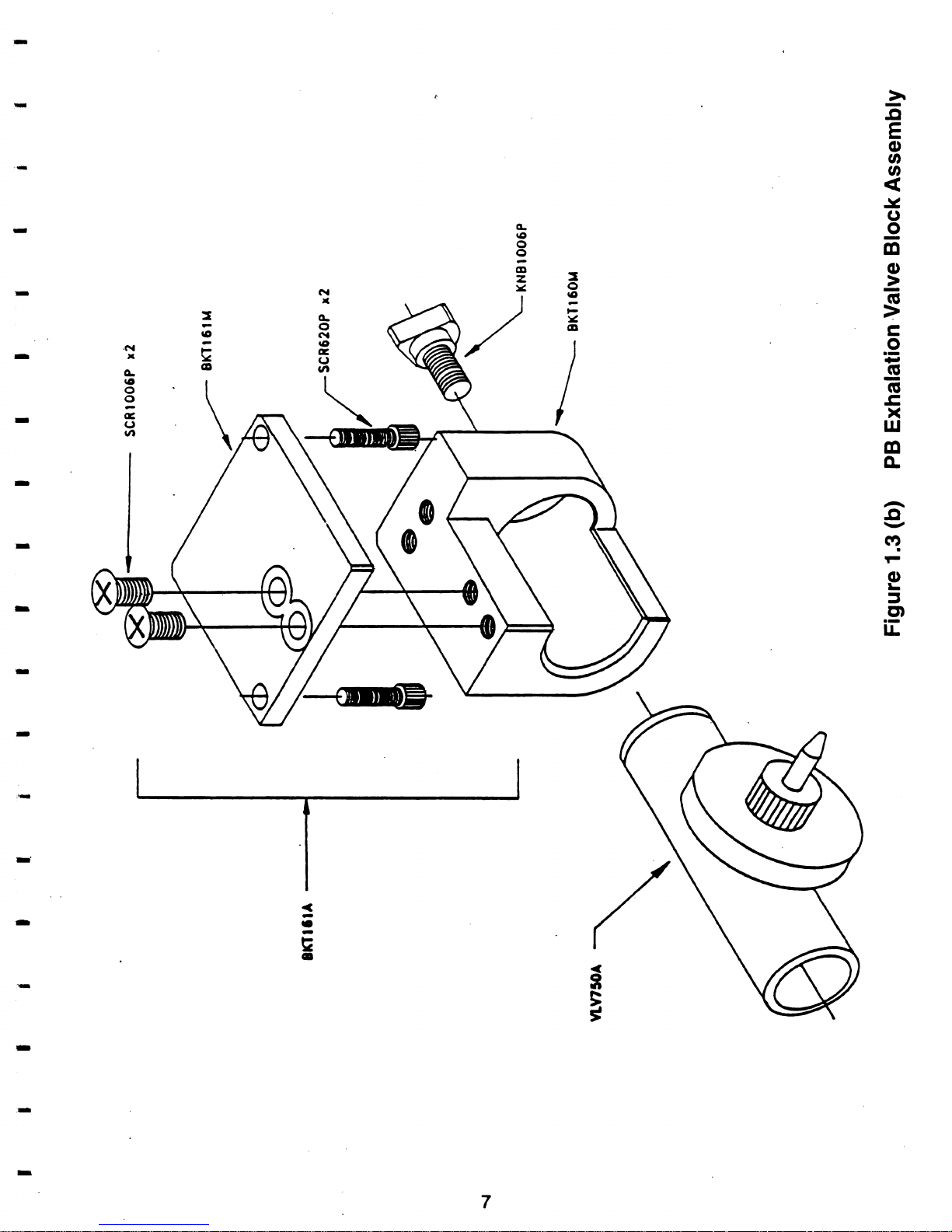
FIGURE 1-3B
PB EXHALATION VALVE BLOCK ASSEMBLY
FIGURE 1-4
WATER TRAP ASSEMBLY
FIGURE 1-5
STANDING POLE ASSEMBLY
Page 5
Table
of
Contents
Drawinqs
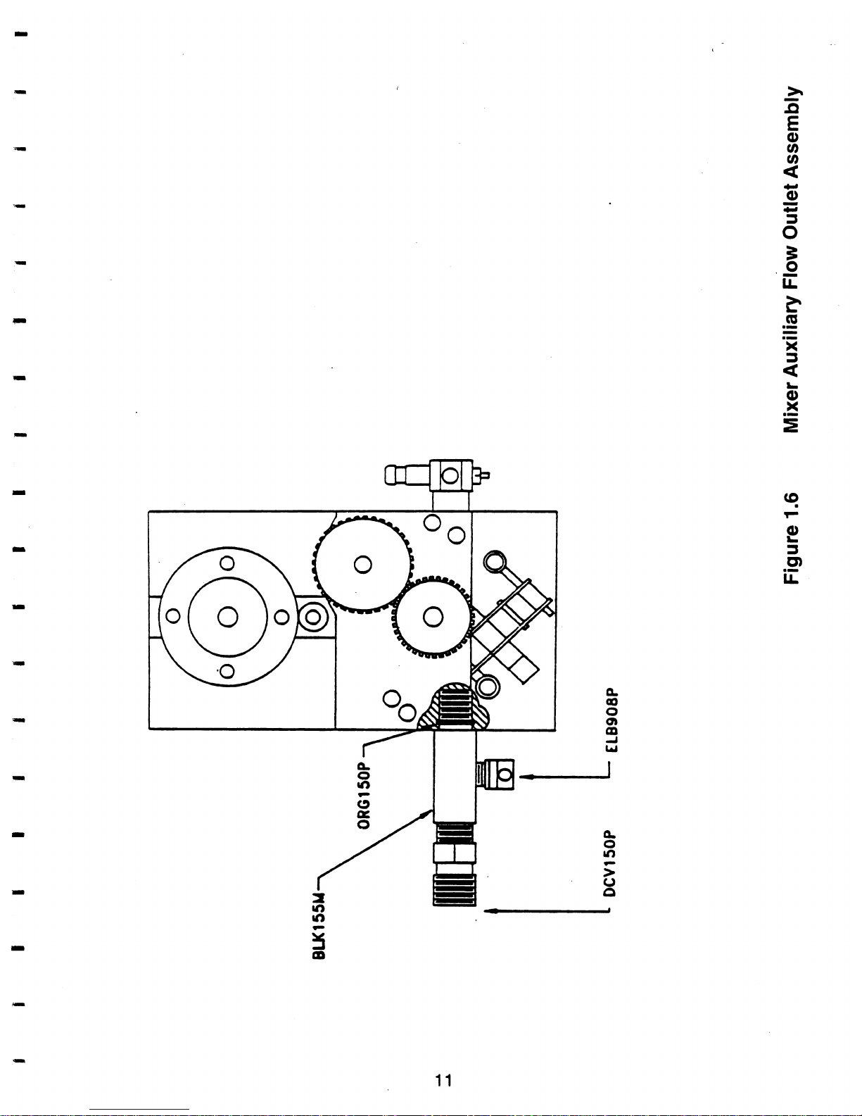
FIGURE 1-6
MIXER AUXILIARY FLOW OUTLET ASSEMBLY
FIGURE 2-1
AIR
/
OXYGEN MIXER
FIGURE 2-2
MANOMETER ASSEMBLY
FIGURE 2-7
PNEUMATIC TUBING DIAGRAM
FIGURE 4-1
BASE PLATE (TOP VIEW)
FIGURE 4-2
BEZEL (FRONT VIEW)
FIGURE 4-3
FRONT PANEL ASSEMBLY
FIGURE 4-4BACK PANEL (INSIDE VIEW)
FIGURE 4-5
BACK PANEL (OUTSIDE VIEW)
FIGURE 4-6
FLOW CONTROLLER AND
LO/HI POTENTIOMETER ASSEMBLY
FIGURE 4-7
SPONTANEOUS FLOW ASSEMBLY
FIGURE 4-8
I.T.
/
R&R POTENTIOMETER ASSEMBLY
FIGURE 4-9
PEEP
/
PIP ASSEMBLY
FIGURE 4-1
0
PNEUMATIC BRACKET ASSEMBLY
Page 6
1
.I
INTRODUCTION
The Newport Breeze Ventilator can be used to ventilate infant,
pediatric or adult patients. It's versatility provides for a safe and
effective use throughout the entire patient range.
This service manual
(Part No. SER150)
contains the necessary
information to enable a
qualified service person
to maintain and
service the
Newport Breeze ventilator. This manual is a companion to
the operating manual
(Part No. OPR150).
Both the operating and
service manuals should be read before any service or repair is
attempted on the Breeze.
Together the manuals will provide the service person with enough
information to operate, maintain and service the Breeze to an
assembly or subassembly level.
We recommend that you do not attempt to make repairs of a complex
nature such as electronic circuit board repairs unless you are a
.fully
qualified service person and possess the appropriate test equipment.
We also recommend that you contact your authorized service
representative or the service department at
NEWPORT MEDICAL
INSTRUMENTS INC.
for circuit board and other complex repairs, as
the
Newport Medical personnel are properly trained and equipped to
provide this service.
If at any time the Breeze cannot be restored to properly operating
condition the unit should be returned to the NMI factory for the service
or repairs as needed.
The material in this manual is organized as follows:
Section One provides a brief description of the
Newport Breeze
Ventilator, options and accessories.
Section Two covers mechanical drawings and parts.
Section Three covers acceptance tests and calibration procedures.
Page 7
Parts, Accessories and Optional equipment may be ordered by part
number through your local NMI dealer or by contacting NMI customer
service.
Customer Service
800 451 .3111
or
949 642 .3910 ext. 282
Fax 949
548 3091
Technical Support
800.451 3111
or
949.642 391 0 ext. 500
Fax 949
548 3091
Newport Medical Instruments Inc.
Corres~ondence:
Post Office Box 2600
Newport Beach, CA 92658
Ship ~roduct to:
760
W,
16th Street, Bldg
B
Costa Mesa, CA 92627
Page 8
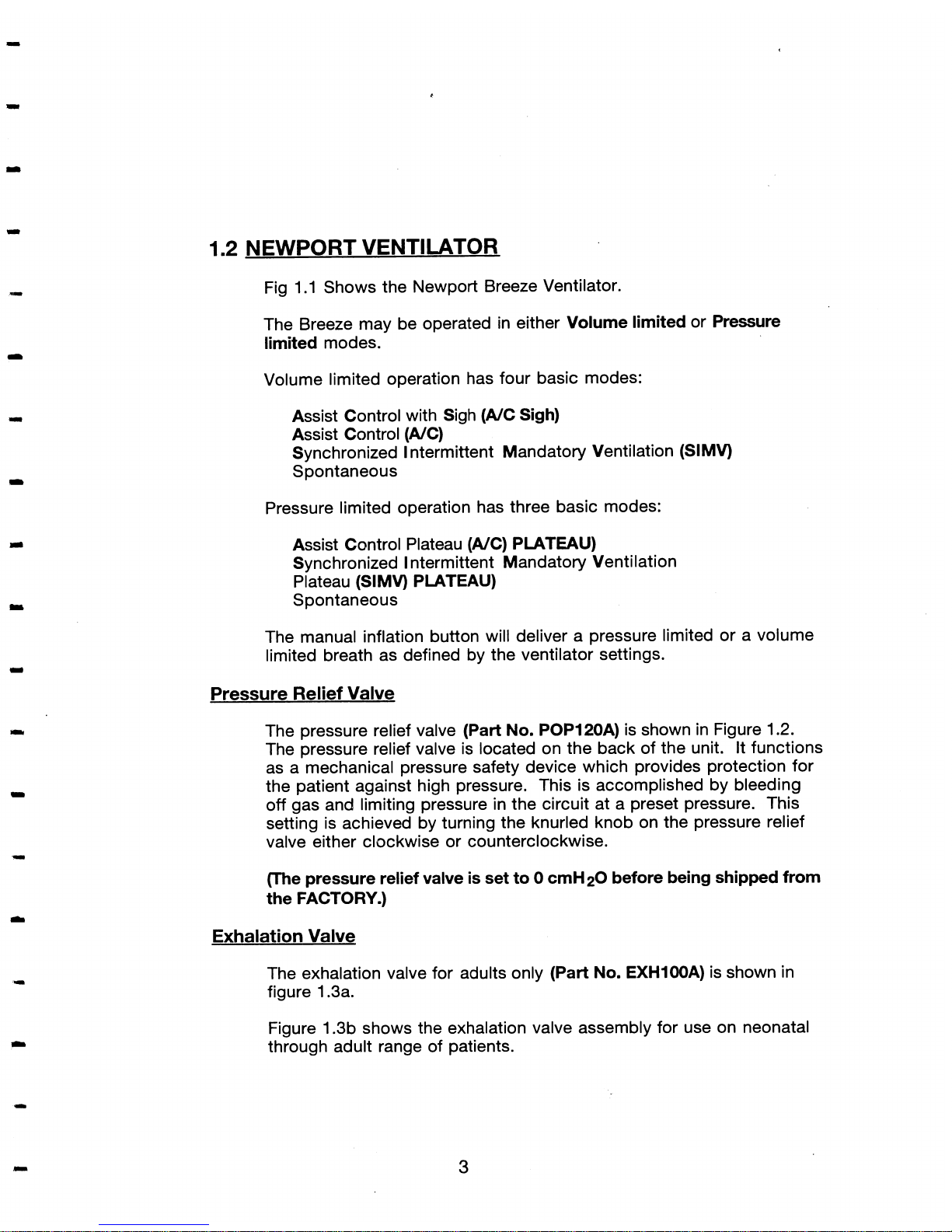
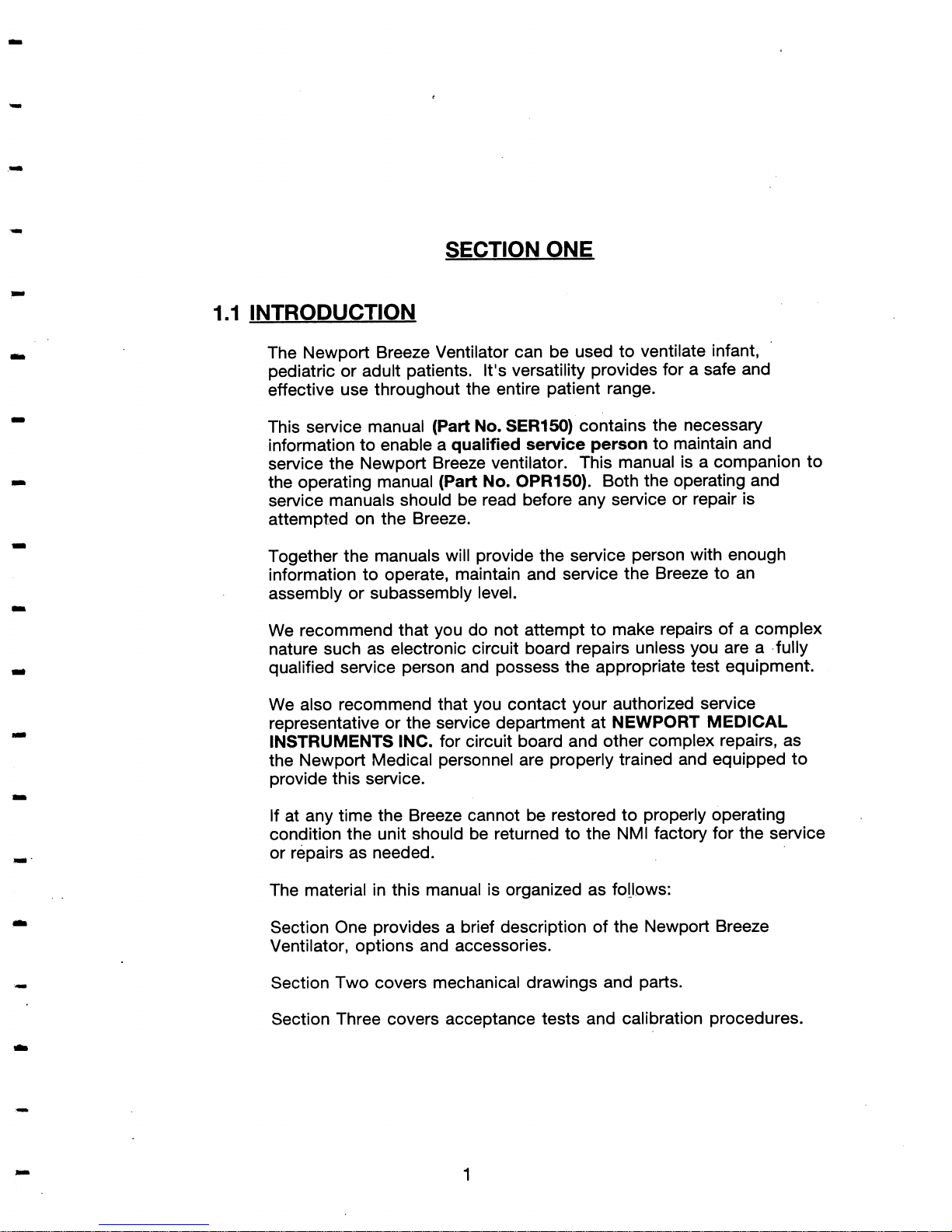
1.2
NEWPORT VENTILATOR
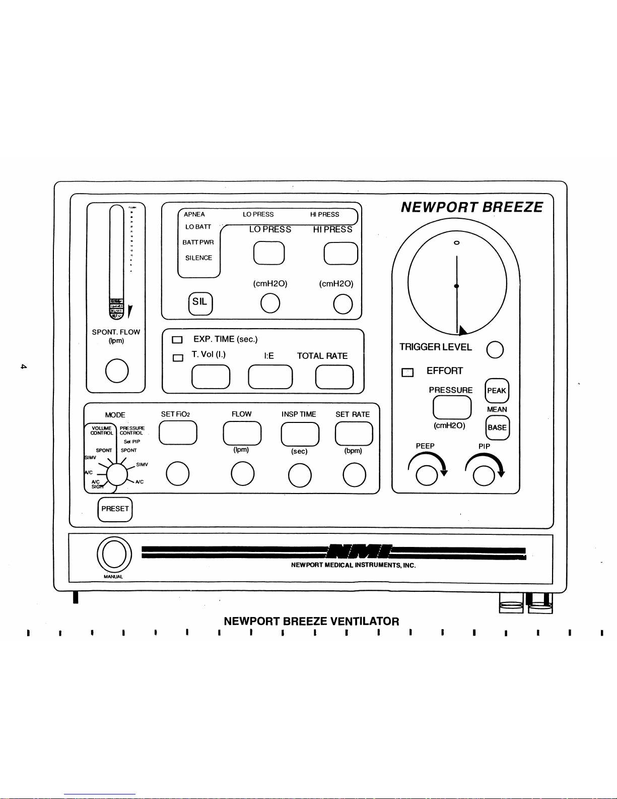
Fig
1.1
Shows the Newport Breeze Ventilator.
The Breeze may be operated in either Volume limited or Pressure
limited modes.
Volume limited operation has four basic modes:
Assist Control with Sigh (AIC Sigh)
Assist Control
(NC)
Synchronized l ntermittent Mandatory Ventilation (SIMV)
Spontaneous
Pressure limited operation has three basic modes:
Assist Control Plateau
(NC) PLATEAU)
Synchronized
l
ntermittent Mandatory Ventilation
Plateau (SIMV) PLATEAU)
Spontaneous
The manual inflation button will deliver a pressure limited or a volume
limited breath as defined by the ventilator settings.
Pressure Relief Valve
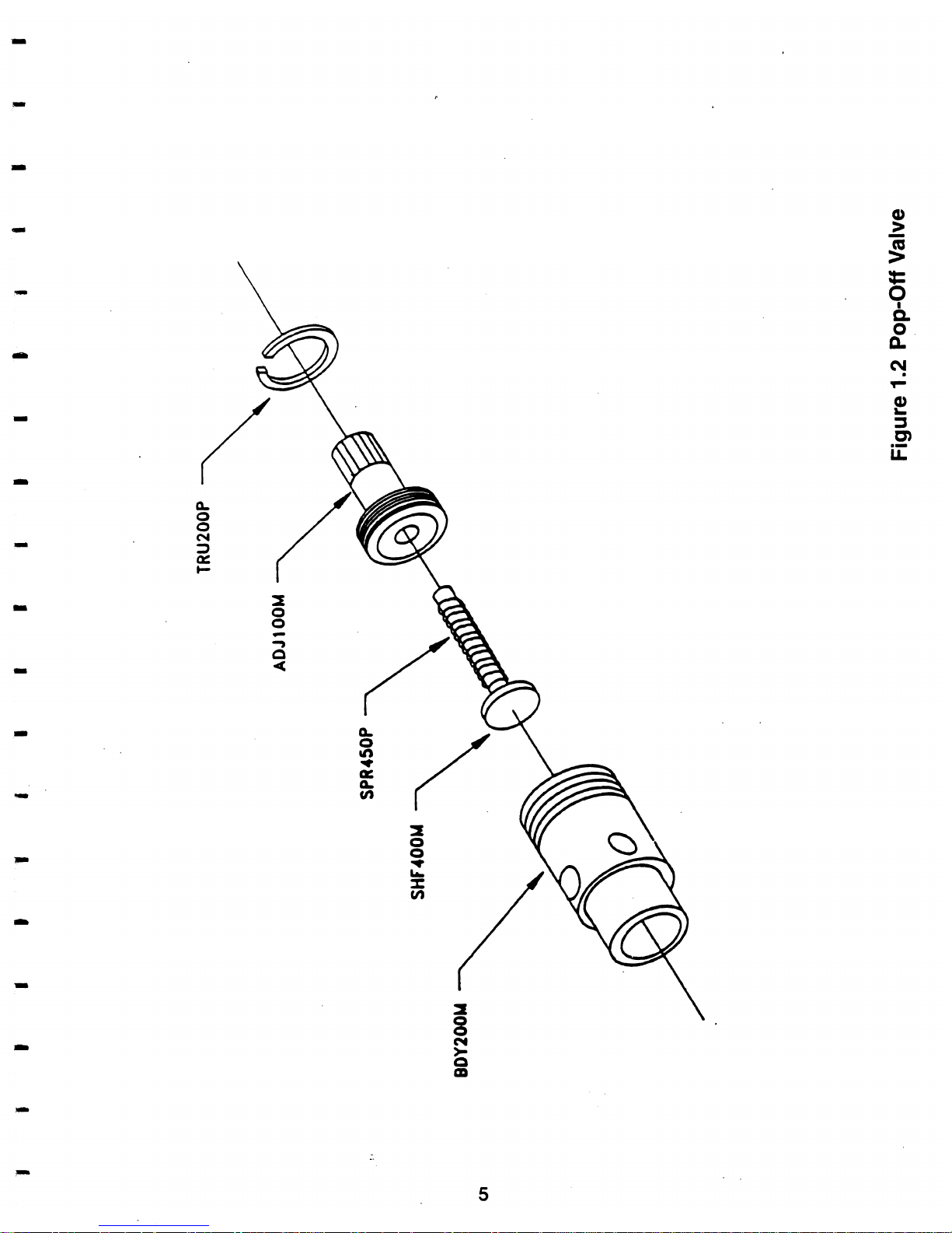
The pressure relief valve (Part No.
POP120A) is shown in Figure 1.2.
The pressure relief valve is located on the back of the unit. It functions
as a mechanical pressure safety device which provides protection for
the patient against high pressure. This is accomplished by bleeding
off gas and limiting pressure in the circuit at a preset pressure. This
setting is achieved by turning the knurled knob on the pressure relief
valve either clockwise or counterclockwise.
(The pressure relief valve is set to
0 cmH2O before being shipped from
the FACTORY.)
Exhalation Valve
The exhalation valve for adults only (Part No.
EXH100A) is shown in
figure
1.3a.
Figure 1.3b shows the exhalation valve assembly for use on neonatal
through adult range of patients.
Page 9
f
3
T
\
<
[APNE
A
LO
PRESS
HI
PRESS
NEWPORT BREEZE
NEWPORT BREEZE VENTILATOR
I
I
I
I
I
I
I
f
\
MODE SET F10z FLOW
l
NSP TI ME SET RATE
vPSU a3NTrnL CONTROL
(1
(-1
(-1
(-1
0
LO
BAlT
LO
PRESS
HI
PRESS
SPONT
SlMV
\
0
SPONT. FLOW
0,
f
3
0
EXP. TIME (sec.)
1.
Vol (I.) I:E TOTAL RATE
cb
TRIGGER 0 EFFORT LEVEL
0
0(3c_>,
PRESSURE
@
(-1
MEAN
(cmH20)
@
\B
6,
L
1
0
MANUAL
NEWPORT MEDICAL INSTRUMENTS, INC.
\
I
1
BAT
PWR
SILENCE
Sel
PIP
SPONT
upm)
(set)
(bpm)
0
0
AJC
AJC
NC
SI
lMV
0
0
0
0,
PRESET
0
\
1
(cmH20) (cmH20)
Page 10
Page 11
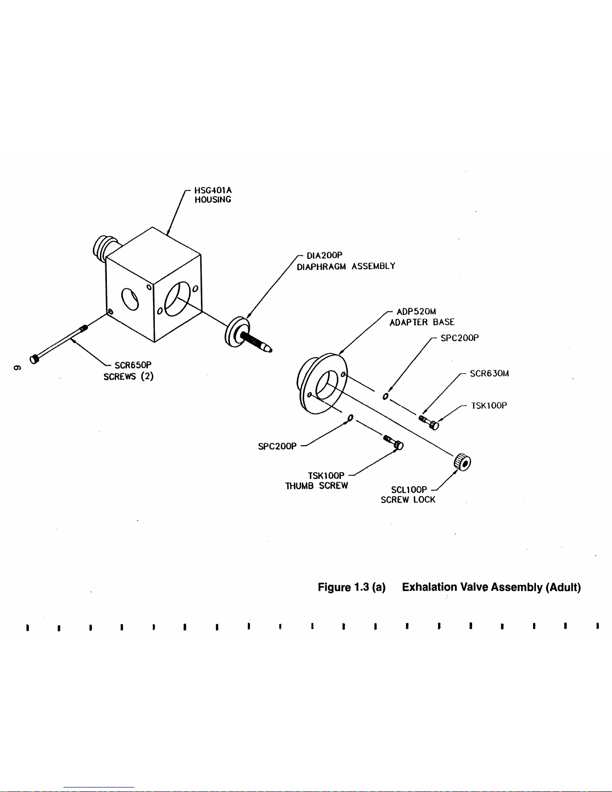
HSG4Ol A
HOUSING
DIA200P
DIAPHRAGM ASSEMBLY
1
/
/
ADP520M
4
/"-
ADAPTER
BASE
SCREWS
(2)
TSKl
OOP
/
THUMB
SCREW
SCLl OOP
SCREW LOCK
Figure
1.3
(a)
Exhalation Valve Assembly (Adult)
Page 12
Page 13
The exhalation valve is mounted beneath the Breeze in the square
area marked EXH VALVE. The exhalation valve controls the release of
the exhaled gas to the atmosphere. The opening and closing of the
valve is controlled by the pressure in the pneumatic drive line, marked
EXP. OUTLET, located beneath the unit and to the left of the
exhalation valve. The drive
line(EXP. OUTLET) is connected to the
exhalation valve .by means of a tubing.
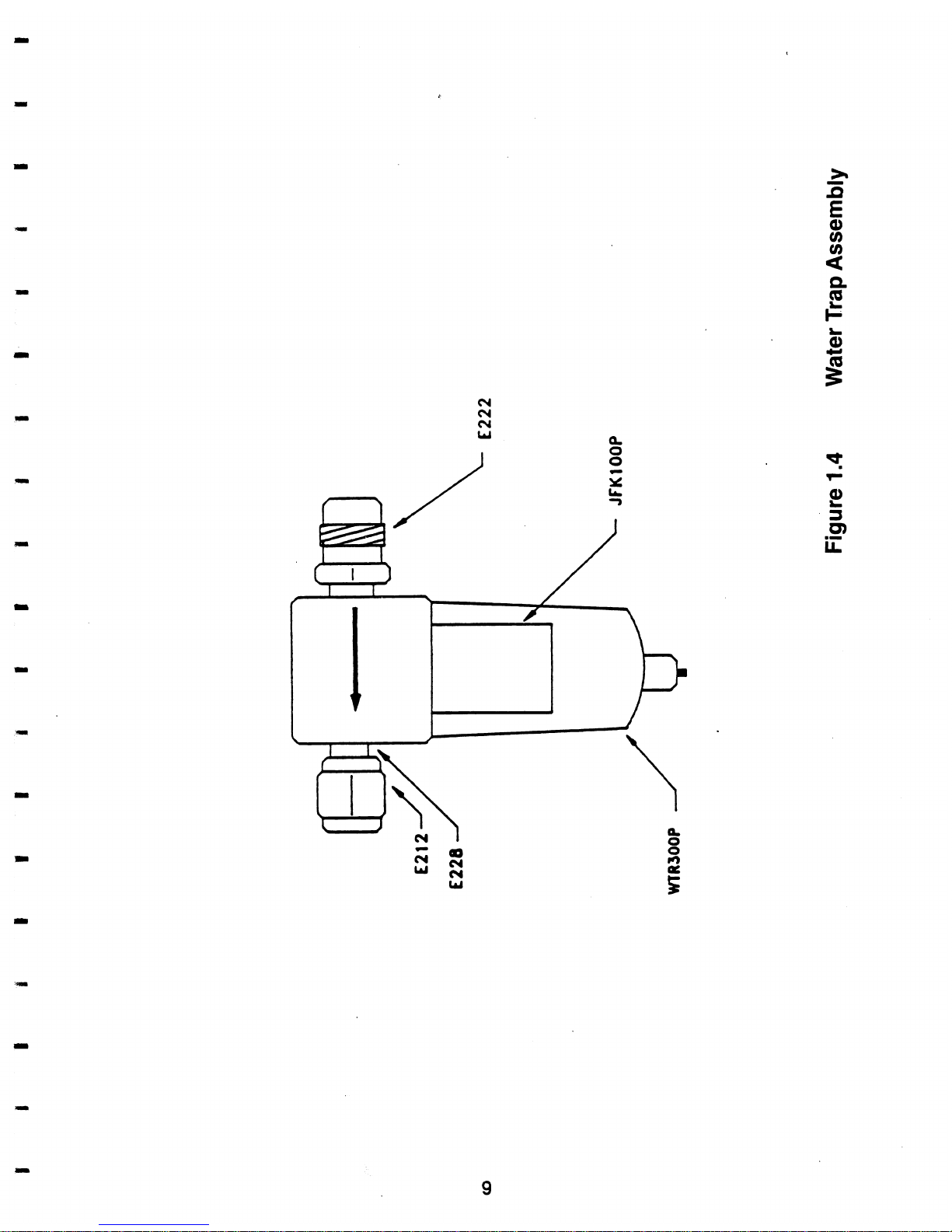
Water Tra~ Assembly
The water trap assembly (Part No. WR300A) is shown in Figure 1.4. It
is mounted to the air inlet connector of the mixer on the rear of the
unit. The water trap helps reduce condensates and contaminates in
the air supply to the unit.
A
drain valve assembly, located at the
bottom of the water trap is opened by pushing upwards to release
contaminates collected in the bowl. Contaminated air enters the
inside of the microfiber element
(.I micron filter) where condensates
and particles are removed from the air stream. Liquids (oil or water)
collect on the elements outer surface and then fall to the bottom of
the bowl.
1.2
STAND AND POLE ASSEMBLY
The stand and pole assembly (Part No. SPA450A) is shown in Figure
1.5. The ventilator is mounted on the stand and pole assembly and is
secured onto the pole by a knob screw. The base has two locking
casters and three non-locking casters. When the casters are in the
lock position they assist in keeping the unit stationed in one location.
I
.3
OPTIONAL ACCESSORIES
Auxiliatv Flow Outlet Assemblv
The auxiliary flow outlet assembly (Part No.AXF150A) is an optional
accessory supplied upon request only. This feature allows the user to
obtain gas flow for various needs. Figure 1.6 shows a unit with the
auxiliary flow outlet assembly.
NOTE:
(AXF150A also includes FLOWMETER FLW300P with
nipple
and tubing.)
Page 14
Page 15

Page 16
Page 17
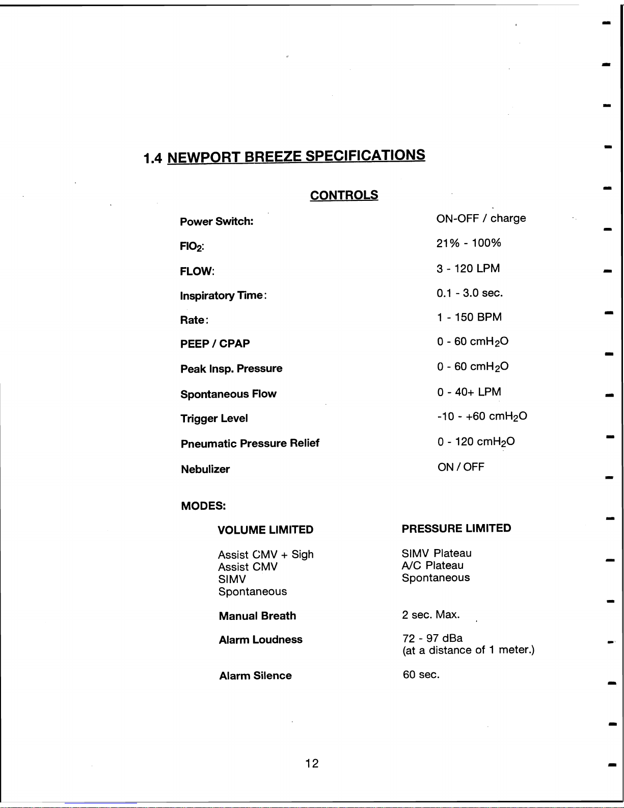
1.4
NEWPORT BREEZE SPECIFICATIONS
CONTROLS
Power Switch:
F102:
FLOW:
lnspiratory Time
:
Rate
:
PEEP 1 CPAP
Peak Insp. Pressure
Spontaneous Flow
Trigger Level
Pneumatic Pressure Relief
Nebulizer
MODES:
VOLUME LIMITED
Assist CMV + Sigh
Assist CMV
Sl MV
Spontaneous
Manual Breath
Alarm Loudness
Alarm Silence
ON-OFF / charge
21
% - 100%
3
-
120 LPM
0.1
-
3.0
sec.
1 - 150 BPM
0 - 60 cmH20
0
-
60 cmH20
0 - 40+ LPM
-10
-
+60 cmH20
0 - 120 cmH20
ON / OFF
PRESSURE LIMITED
SlMV Plateau
A,C Plateau
Spontaneous
2
sec. Max.
72
-
97 dBa
(at a distance of 1 meter.)
60
sec.
Page 18
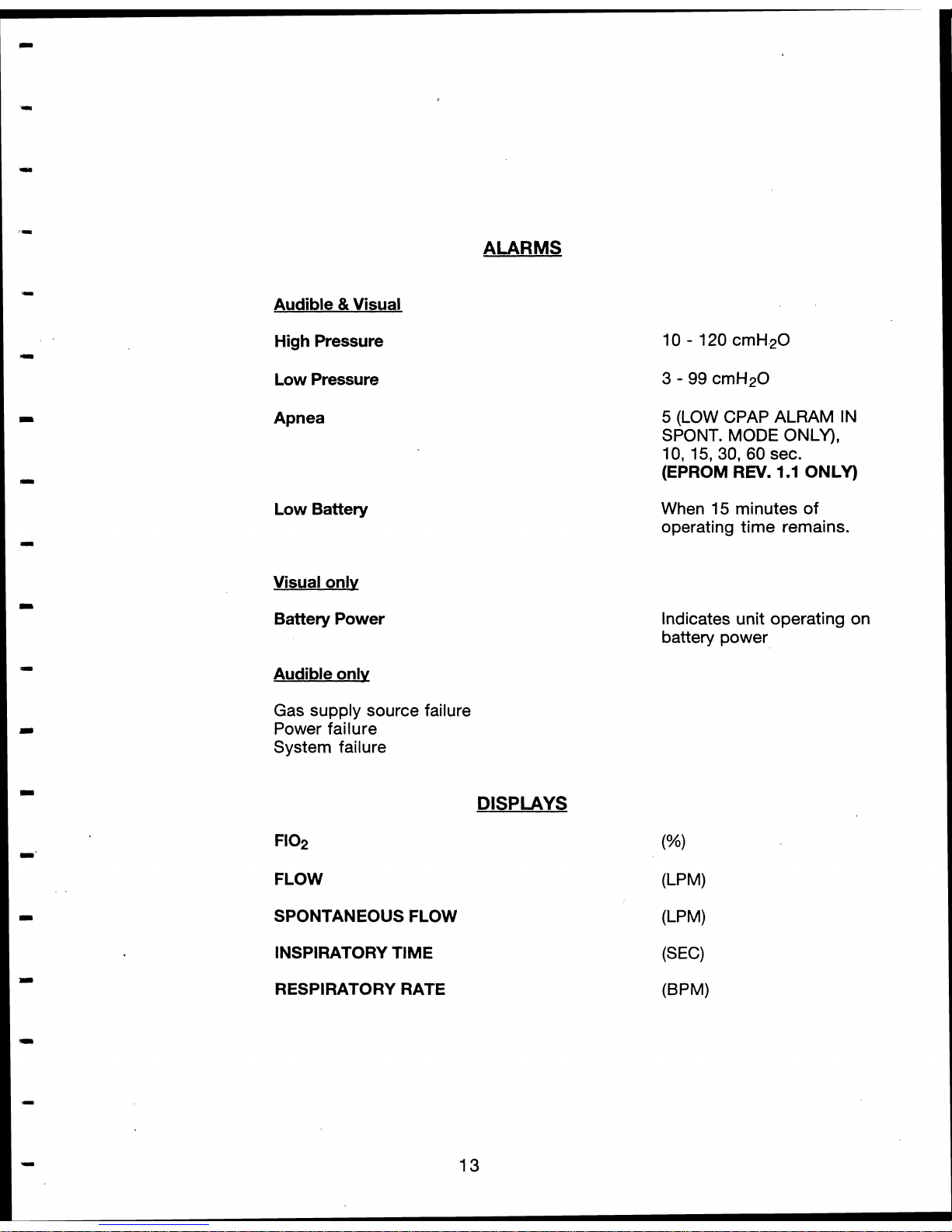
Audible & Visual
High Pressure
Low Pressure
Apnea
Low Battery
Visual onlv
Battery Power
ALARMS
Audible only
Gas supply source failure
Power failure
System failure
DISPLAYS
F102
FLOW
SPONTANEOUS FLOW
INSPIRATORY TIME
RESPIRATORY RATE
5
(LOW CPAP ALRAM IN
SPONT.
MODE
ONLY),
10, 15, 30, 60
sec.
(EPROM
REV.
1.1
ONLY)
When
15
minutes of
operating time remains.
Indicates unit operating on
battery power
Page 19
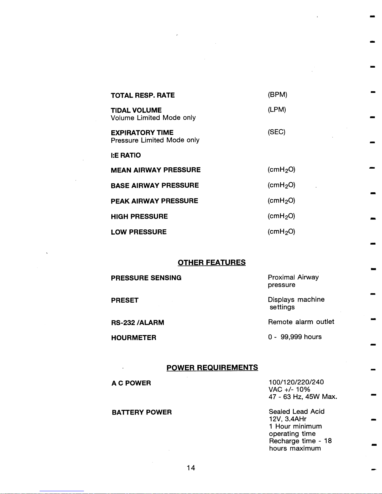
TOTAL RESP. RATE
TIDAL VOLUME
Volume Limited Mode only
EXPIRATORY TIME
Pressure Limited Mode only
I:E RATIO
MEAN AIRWAY PRESSURE
BASE AIRWAY PRESSURE
PEAK AIRWAY PRESSURE
HIGH PRESSURE
LOW PRESSURE
OTHER FEATURES
PRESSURE SENSING
PRESET
Proximal Airway
pressure
Displays machine
settings
RS-232 /ALARM
Remote alarm outlet
HOURMETER
0
-
99,999
hours
POWER REQUIREMENTS
A C POWER
BAlTERY POWER
1
00/120/220/240
VAC
+/-
1
0%
47
-
63 Hz, 45W
Max.
Sealed Lead Acid
12V,
3.4AHr
1
Hour minimum
operating time
Recharge time
-
18
hours maximum
Page 20
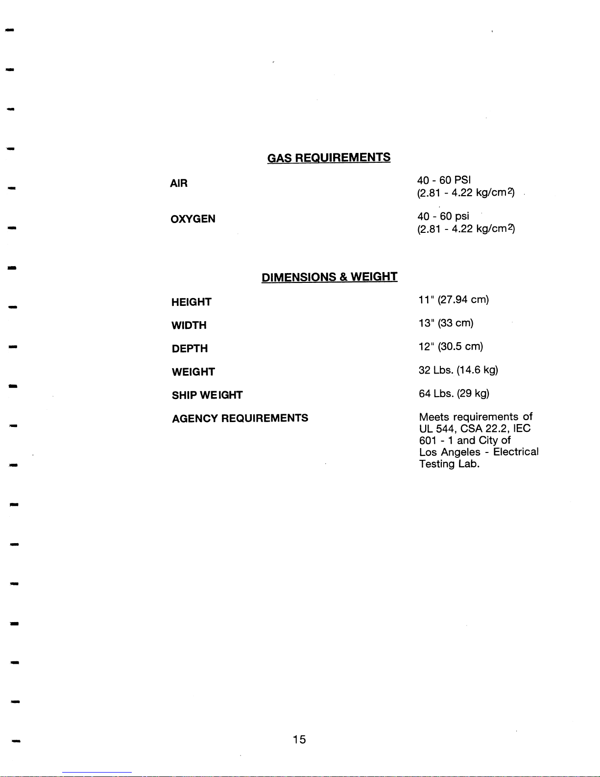
GAS REQUIREMENTS
AIR
OXYGEN
40 - 60 PSI
(2.81
-
4.22 kg/cm2)
40 - 60 psi
(2.81
-
4.22 kg/cm2)
DIMENSIONS & WEIGHT
HEIGHT
11 " (27.94 cm)
WIDTH
13" (33 cm)
DEPTH
12" (30.5 cm)
WEIGHT
32 Lbs. (14.6 kg)
SHIP WEIGHT
64 Lbs. (29 kg)
AGENCY REQUIREMENTS
Meets requirements
of
UL 544, CSA 22.2, IEC
601
-
1 and City
of
Los Angeles - Electrical
Testing Lab.
Page 21
SECTION TWO
INSTRUMENT DESCRIPTION
2.1
GENERAL
A
simple functional description and principle of operation of the
Newport Breeze is presented in this section.
The function of various
components, different modes and various settings are also explained.
2.2
POWER SOURCE
The ventilator may be powered by an electrical supply of IOOvac,
120vac, 220vac or 240vac
+/-
10% at 47
-
63
Hz, 45W maximum. The
voltage adjustment on the power entry module located at the rear of
the unit must be set for the supply voltage.
2.3
SOLENOIDS AND VALVES
The Newport Breeze has four solenoids and four valves. The solenoids
are electronically controlled and the valves are pneumatically
controlled by the solenoids. The function, switching cycles and control
methods of these components are explained in Table 1 and Table 2.
The reader is advised to refer to pneumatic diagram Figure 2.7.
Page 22

2.3
TABLE
1
Valvel
Solenoid
Flow Pilot Solenoid
PEEP Solenoid
Plateau Solenoid
Nebulizer Solenoid
Main Flow Valve
Spontaneous Flow Valve
Plateau Valve
PEEP/Exhalation
Part
Number
PLV150P
PLV300P
PLV350P
PLV250P
SOL200P
VLV150P
VLV150P
VLV150P
Function
Control of main flow valve
and spontaneous flow valve.
Control of PEEP and
exhalation valve.
Control of Plateau valve.
Control of Nebulizer output
Control Valve Main flow
output.
Control Spontaneous
flow output.
Control of Plateau pressure.
Controls PEEP and
Expiratory drive line
pressure.
Page 23

2.3
TABLE
2
NOTE:
During SPONTANEOUS
-
PEEP solenoid is always closed except
during manual breath and the peeplexhalation solenoid is NC
(normal closed) to load.
Normal:
OPEN ONLY WHEN NEBULIZER SWITCH IS TURNED ON.
Controlled by
electronics
electronics
electronics
electronics
flow pilot
solenoid
flow pilot
solenoid
plateau solenoid
PEEP solenoid
S
=
SOURCE,
L
=
LOAD,
EXH
=
EXHAUST
Condition
Expiratory Phase
closed
closed
open
closed
open
closed
open
L- S
S- L
EXH- L
L-
EXH
EXH
-
L
L- EXH
Valve1
Solenoid
Pilot Solenoid
PEEP Solenoid
Plateau Solenoid
Nebulizer Solenoid
Main flow Valve
Spontaneous Flow
Valve
Plateau Solenoid
PEEP/Exhalation
Valve
Part
Number
PLV150P
PLV300P
PLV350P
PLV250P
SOL200P
VLV150P
VLV150P
VLV15OP
Condition
lnspiratory Phase
open
open
In pressure limited
open
In volume limited
closed
normal
open
closed
pressure limited:
open between
L-
S
S- L
volume limited:
EXH- L
L- EXH
S- L
L- S
Page 24

2.4
AIR
1
OXYGEN
MIXER
The air/oxygen mixer has the dual function of mixing air and oxygen to
a desired
F102 and regulating the output mixture to a preset pressure.
The pressure of the air and oxygen supply gases are lowered to 2.0
kg/cm2 (28.5 psi) by means of a diaphragm and regulator assembly.
The regulated gases are then mixed and supplied at the desired
F102.
The input pressure of the gases must be between 40 - 60 psi for the
mixer to maintain accurate
F102 and regulate the output pressure.
Figure
2.1
displays the four output ports of the mixer.
(1)
Main Flow port:
Supplies the main flow of the unit.
(2) Continuous Flow port:
Supplies bleed flow to the atmosphere. This flow is the
minimum flow required out of the mixer to maintain the
F102
within specifications.
(3)
Auxiliary Flow port:
Supplies the Spontaneous flow and Auxiliary flow to the
unit.
(4) Air Port:
Supplies gas to the pneumatic control circuit and is equal to
the input pressure of the air side.
Page 25

MIXER
ASSEMBLY
(AUXILIARY FLOW PORT)
Y
-PASS
OUTLET
FIG.
2-1
Page 26

2.5
PRINTED CIRCUIT BOARDS
The
NEWPORT
BREEZE
has three printed circuit boards which
control and display its functions:
These are:
(1) The power board (PCB
420A).
(2) The main (CPU) board (PCB 410A).
(3)
The display board (PCB 400A).
The power board is located on the back panel. It receives AC input
power from the transformer and it rectifies the AC to DC and then
regulates the DC output voltage to the battery, hourmeter and the
main (CPU) board.
The CPU board is located in the top portion of the unit and contains
the electronic circuitry that controls and monitors the operation of the
unit.
The display board is located behind the front panel and consists of
LEDs which display the various settings and alarms as determined by
the CPU board.
2.6
MANOMETER ASSEMBLY
The manometer assembly (Part No. MAN120A, Figure 2.2) consists of
the manometer and the trigger level mechanism. The manometer has
a pressure range of -1 0 to 120
cmH20. The trigger level mechanism
consists of a photocell (for sensing patient inspiratory effort) and a
gear and shaft assembly for trigger level setting. The photocell is
attached onto the trigger level indicator such that the needle passes
through the photocell and cuts it's photo beam each time the
instantaneous inspiratory pressure equals the trigger level setting.
This cutting of the photo beam is sensed by the electronic circuitry
2nd is used as a means of sensing patient effort.
Page 27

SHF001
A
FIG.
2-2
Page 28

2.7
THEORY
of
OPERATION
2.7.1 GENERAL
The theory of operation of the ventilator in the volume limited and
pressure limited modes will be discussed in this section. We shall
study the path of gas flow from the mixer to the main flow outputs. We
shall consider various conditions that affect or change the flow path.
The inspiratory time, respiratory rate,
F102 and the amount of flow will
not be considered since these do not affect the flow path. They will
only determine the quantity, quality and duration of the flow. An
understanding of the switching of the solenoids and valves is
important in tracing the flow of gas and the outputs in the
Newport
Breeze.
2.7.2 VOLUME LIMITED MODES
The flow path in the three modes
(A)
Assist Control + sigh (NC + sigh)
(B) Assist Control
(NC)
(C) Synchronized l ntermittent Mandatory Ventilation (SIMV)
is different only in the pattern in which it is delivered. The difference
between
A/C and
A/C
+
Sigh is that in A/C + Sigh the first breath has
an inspiratory time 1.5 times that of the setting and thereafter every
100th breath is equal to 1.5 times the inspiratory time setting. The
difference between
A/C and SlMV is in the timing of the delivered
breath. In SlMV the timing of the synchronized breaths is set by the
respiratory rate.
EXAMPLE:
If the respiratory rate is set at 6 BPM then the
Synchronized Timing Period
=
60 / 6 = 10 seconds. The
10
sec. is divided into a 75% and 25% window. A breath
can not be initiated during the 75% window. The
machine watches for the patient effort during the
25%
window and will deliver a breath when a patient effort is
sensed. If no patient effort is sensed the machine will
deliver a breath at the end of the
25%
window.
In the
A/C mode a breath is delivered each time an inspiratory patient
effort is sensed regardless of the respiratory rate setting, while the
SlMV breaths are delivered only at the respiratory rate setting.
Page 29

FLOW
PATHS
Figure
2.3
and Figure
2.4
show the path of flow during the inspiratory
and expiratory phase in the volume limited
A/C
mode.
INSPIRATORY PHASE
In the inspiratory phase the flow pilot solenoid receives an electrical
signal which opens the solenoid. This sends a pneumatic signal to the
master valve. The master flow valve opens allowing gas to flow
through the main flow valve tubing into the main flow adapter
assembly from where it is delivered to the breathing circuit. At the
same instant the spontaneous valve (which is normally open) receives
a pneumatic signal which shuts off the spontaneous flow.
The Plateau solenoid is off and the plateau valve is closed during
volume limited modes which allows flow between the exhaust
(EXH)
and load
(L)
ports.
The PEEP solenoid receives an electrical signal during each
inspiratory cycle. This signal opens the solenoid, supplying a
pneumatic signal to the
PEEP/Exhalation valve which opens allowing
gas flow between supply
(S)
and load
(L)
ports. The gas from the
auxiliary
flow block passes through the plateau valve into the
PEEP/Exhalation valve and then into the Expiratory drive line. This
causes a pressure build up in the Expiratory drive line. The Exhalation
valve closes resulting in gas flow to the patient.
Page 30

-
Emergency Intake
Valve
-
I
Microprocessor
I
NEWPORT
BREEZE
VENTILATOR
Pneumatic
Diagram
Volume limited mode, inspiratory phase
Fig.
2-3
Exh.: Exh.
Port
S: Supply
Port
L: Load Port
Page 31

b-
--------.-.-
-.--..-..----.--.----.--------
1
ri
=
I
w
Microprocessor
a
Y
-
L
m
1
m
1
NEWPORT
BREEZE
VENTILATOR
rn
Pneumatic Diagram
Volume limited mode, expiratory phase
(PEEP
ON)
-
Exh.: Exh.
Port
S: supply
port
Fig.
2-4
L:
Load Port
Page 32

EXPIRATORY PHASE
At the beginning of the Expiratory phase the electrical signal to the
PEEP solenoid is turned off, which closes it. The pneumatic signal to
the
PEEP/Exhalation valve is removed and the valve closes. The gas
in the peep valve now flows only between the
load(L) and
exhaust(EXH). If PEEP is set at 0 cmH20 there is no gas flow from the
PEEP regulator into the PEEP venturi assembly. The gas from the
expiratory drive line flows back into the
PEEP/exh. valve and bleeds
out of the PEEP venturi assembly.
The expiratory drive line pressure
falls to
0
cmH2O and the exhalation valve opens allowing the patient
to exhale.
If the PEEP were set above zero, then at the end of inspiration, the gas
from the PEEP regulator would flow into the PEEP venturi assembly,
and through the
PEEP/Exhalation valve to maintain the expiratory
drive line pressure. The expiratory drive line pressure depends on the
PEEP setting. The expiratory drive line pressure will close the
exhalation valve enough to maintain the PEEP pressure in the
breathing circuit. The PEEP pressure in the circuit is read on the
manometer or baseline pressure display during expiration. In normal
operation the PEEP pressure is always set below peak inspiratory
pressure. In the expiratory phase the spontaneous valve is open and a
spontaneous flow (depending on the settings), flows through the
circuit.
Page 33

2.7.3
PRESSURE LIMITED MODES
The pressure limited modes
(a) Assist Control Mechanical Ventilation with Plateau
(AK
Plateau)
(b)
Spontaneous Intermittent Mechanical Ventilation/ Plateau
(SIMV/ Plateau)
differ from one another in the same way as in the volume limited
mode. In the pressure limited modes each breath is limited in
inspiratory pressure by the peak inspiratory pressure (PIP) setting. The
PEEP/exhalation valve controls the expiratory drive line pressure
which limits the maximuminspiratory pressure. In the pressure limited
modes the path of main flow and spontaneous flow is similar to that of
the volume limited mode. Figure
2.5
and Figure
2.6
show the path of
gas flow in the inspiratory phase and expiratory phase respectively.
The operation of PEEP and PIP (Peak lnspiratory Pressure) in the
pressure limited modes is as follows:
With
PEEP
In the inspiratory phase the PEEP solenoid receives an electrical
signal thereby supplying a pneumatic signal to the
PEEP/exhalation
valve which opens allowing gas to flow between the load
(L)
and supply
(S) ports. Air flows into the plateau regulator and the regulated output
flows through the plateau venturi assembly, and this generates the
control pressure which flows into the PEEP plateau assembly. This
gas flows out of the
PEEP/Exhalation valve into the expiratory drive
line building up a pressure which depends on the plateau (PIP)
regulator setting. The main flow at this time flows into the breathing
circuit where it is confined by the exhalation valve. When the pressure
of the gas in the breathing circuit exceeds that of the expiratory drive
line pressure the exhalation valve opens up partially to bleed off the
excess gas and thereby maintains the Peak lnspiratory Pressure (PIP).
Page 34

In the expiratory phase the PEEP solenoid is closed and therefore the
PEEP/Exhalation valve is in the normally closed condition. It allows
flow through the Exhaust and Load ports. The gas from the PEEP
regulator flows into the
PEEP/Exhalation valve through its venturi
assembly. The excess gas is bled off from the venturi assembly. An
increase or decrease in the expiratory drive line pressure is obtained
by adjusting the PEEP pressure regulator. This results in a similar
change in the exhalation valve, and thus the PEEP pressure.
WITH
NO
PEEP
With PEEP off (i.e. set at zero) the opening and closing of the valves
and solenoid is similar to the case with PEEP on. Since there is no
flow out of the PEEP regulator, there is no flow into the PEEP venturi
assembly or into the
PEEP/Exhalation valve, so at end of the
inspiration cycle the gas in the expiratory drive line bleeds out of the
PEEP venturi base assembly dropping the pressure in the expiratory
drive line to
0
cmH20 and subsequently the exhalation valve opens
allowing the patient to exhale. This in turn results in a drop in pressure
in the breathing circuit and lung to zero.
Page 35

Emergency
Intake
Valve
-
'1.
m
-
m
G
Microprocessor
m
-
a
L
I
-,
.
-
NEWPORT
BREEZE
VENTILATOR
1
Pneumatic Diagram
Pressure limited mode, inspiratory phase
-
Exh.: Exh.
Port
S:
Supply
Port
L:
Load
Port
Fig.
2-5
Page 36

Emergency Intake
Valve
I
=*
I
w
-
d
m
Exh.: Exh.
Port
S:
Supply
Port
L:
Load Port
NEWPORT
BREEZE
VENTILATOR
Pneumatic
Diagram
Pressure limited mode, expiratory phase.
(PEEP
ON)
Fig.
2-6
3
1
Page 37

Figure
2.7
El50
Breeze Pneumatic Diagram
Page 38

2.7.4
SPONTANEOUS MODES
In the spontaneous modes
(A)
Volume Limited
(B)
Pressure Limited
there is continuous flow into the breathing circuit from the
spontaneous flow valve depending on setting. If PEEP is set to some
value the gas flow from the PEEP regulator flows into the venturi base
assembly, and into the PEEP valve and then into the expiratory drive
line. This flow results in a pressure build up in the expiratory drive line
resulting in PEEP.
If the
manual breath button is depressed in the spontaneous mode the
ventilator will deliver a breath whose characteristics depend on the
ventilator settings, which are displayed when the preset switch is
depressed. In the volume limited spontaneous mode the ventilator will
deliver a volume limited breath as per the machine settings. While in
the pressure limited spontaneous mode the ventilator will deliver
a
pressure limited breath as per the machine settings.
2.7.5
NEBULIZER
The nebulizer is operational when the
NEB.
switch located on the front
of the unit behind the door is turned "ON". When the switch is turned
"ON" an electrical signal is supplied to the Nebulizer solenoid, which
opens. The opening of the solenoid allows gas to flow from the main
flow and out to the nebulizer through the outlet located on the right
hand side the unit. The gas flows in the nebulizer circuit only during the
inspiratory cycle. The nebulizer flow is about
6
LPM (100 cclsec).
When the nebulizer switch is turned on the tidal volume displayed
takes into account the flow through the nebulizer and adds the
apprcpriate volume to the display tidal volume.
Page 39

SECTION
3
CALIBRATION AND OPERATIONAL VERIFICATION PROCEDURE
3.1
GENERAL
This section. describes the various test and calibration procedures.
The unit should be tested periodically to verify that operation is within
the specifications. The Operational verification should be performed at
least every month. If the BREEZE is subjected to heavy usage the
frequency of the operational verification should be increased
accordingly. All alarms (audible and visual) and the
F102 should be
checked regularly (every
24
hours) if the unit is used continuously.
NOTE: The unit should be inspected each time new usage is begun.
3.2
PREVENTATIVE MAINTENANCE
Preventive Maintenance on the ventilator should be completed after
every 3000 hours of operation (or earlier if required), or a minimum of
once each year. The Preventive Maintenance is intended to be done
in the hospital.
The preventive maintenance includes:
*
Visual inspection of external surfaces, controls,
attachments and accessories.
*
Replacing the Air and O2 mixer inlet filters (part no.
MFK11 OA).
Cleaning the air inlet Water Trap (WTR300P) and replacing
the jar filter
(JFK100P).
*
Removing top cover and visually inspecting the interior, all
tubing, wires and wiring connectors,
screws,nuts and
hardware, checking the general condition of the
components.
*
Performing operational verification on the unit and
recalibration of the unit if required.
CAUTION
:
Do not use strong solutions for cleaning the unit. Use
only alcohol or a mild soap solution.
Page 40

Overhaul
The ventilator should be overhauled every 3 years or after 15000 hours
of operation or more often if required. The overhaul
s.hould be
performed by a
Newport Medical service technician at the factory
service center.
Iri addition to the items performed during Preventive
Maintenance, an overhaul will include the overhaul of the
Air/02 mixer
and replacement of moving parts if required. Contact NMI customer
service for further information on the above service.
3.3
OPERATIONAL VERFCATlON
AND
CALIBRATION PROCEDURES
This procedure is included to assist the Qualified Operator or Hospital
Service Technician in establishing a routine verification procedure to
verify that the
BREEZE
ventilator is in operating condition. The
procedure is explained and is intended to help test the unit after
repair/replacement of parts on the unit.
CAUTION: Before using any test equipment for calibration, verify
that the accuracy of the instrument is certified by a
testing laboratory whose master test instruments are
traceable to The National
Institute of Standards and
Technology or equivalent.
Preliminary Adjustments:
The Preliminary adjustments are done at the factory and need not
be
adjusted unless the parts that directly affect them are replaced.
Connect Air and
O2
sources to their respective inlets at the rear of the unit.
1.
Input Voltage:
Adjust the power input on the power entry module
on the back of the unit to desired input voltage.
For
U.S.A.:
120 vac., 1A
Page 41

2. a). Pull out the tubing at the output of the pressure regulator for
PEEPIPlateau supply.
b). Hook a standard pressure gauge to it.
c). Adjust the regulator output to read 25 psi.
d).
Reattach tubing.
3.
Transducer adjustments:
a. R14 (Reference voltage)
1. Measure the voltage across VREF TP3 and Pin
7
of I.C. U20
on the CPU PC board (PCB41
OA).
2. Adjust trim pot R14 to adjust the voltage read to 5 volts.
b. R22 (Transducer offset)
1.
Fix a jumper on
JP1 on CPU PC board.
2.
Turn the mode selector switch to spontaneous mode.
3.
Adjust the pot R22 (offset) to get a pressure display
readout of
0
cmH20. (The left digit display of the
pressure display helps adjust the precise zero value.
When the adjusted value is towards the positive side the
top segment of the left display shall light up and the
bottom segment shall light up when the adjusted zero
value is towards the negative end. The pot R22 should
be adjusted so that the display toggles between the two
segments indicating the most precise zero value.)
c. R27 (Transducer gain)
1.
Pull out the tubing that feeds the manometer and the
pressure transducer at the tee.
1-
Pull Out
I/
-
-1
1-
to manometer <--------I tee1
OOD
I-------- > to Transducer
Page 42

2.
Fix a syringe (150cc) at the tee.
3.
With the
help of the Syringe build a pressure of 60
cmH20 in the assembly so that the manometer reads 60
cmH20.
4.
Adjust pot RZ7 so that display reads 60 cmH20.
NOTE: REPEAT
steps (b) and (c) after each time the pots
are adjusted.
5.
REMOVE JUMPER
on JP1 on CPU board.
6.
RECONNECT TUBING.
d. R4 (Battery charging voltage)
CAUTION: Caution must be taken to avoid a short between the
battery terminals.
1.
Remove the positive
terminal to input of the battery.
2.
Hold a voltmeter across the terminal and fuse mounting
contact of fuse fl of the power supply board
(PCB420A).
3.
Connect a load resistor(
e.g. 1.5K ohm, 112 watt)
between the positive input
terminal of the battery and
the voltmeter probe.
4.
Adjust R4 (BATT CHARGE) on the power PC board on
the back
panel so that the charging voltage read by
voltmeter is 13.8 volts.
5.
Reconnect the wire onto the battery.
OPERATIONAL VERIFICATION AND CALIBRATION PROCEDURE
Set up the unit with the standard breathing circuit as shown in
fig
3-1.
Connect the input Air and
O2
supply lines at the input to the ventilator
located at the rear of
thb unit. Adjust the input pressures of the input
gases to 50 psi.
Page 43

CONNECT TO MAIN FLOW OUTLET
FOR CALIBRATION OF:
1.
SPONTANEOUS FLOW
2.
MAIN FLOW
3.
RESPIRATORY RATE
4.
INSPIRATOR TIME
5.
A/C SIGH
EXP. OUTLET
Y
EXHALATION VALVE
-
RESERVOIR
1
LITER TEST LUNG
SPASSOA
BAG
Figure
3.1:
BREEZE
TEST
SET-UP
Page 44

NOTE:
For several of the operational verification tests we have used the
calibration analyzer series RT-200 manufactured by Timemeter
Instrument Corporation. However any flow measuring instrument
capable of reading flows up to 120 LPM may be used.
Gas
Input Pressure Alarm Test:
1.
Adjust the pressure of input air source to 50 psi.
2.
Reduce the pressure of the input
02
source slowly and note
the pressure at which the low input pressure alarm sounds.
Verify that the alarm sounds when the pressure of the
source is 31
+
3 psi.
3.
Adjust the pressure on the
O2 side to 50 psi.
4.
Reduce the pressure on the Air source side slowly and verify
that the alarm sounds when the pressure drops to around 31
+
3 psi. If the low gas input pressure alarm fails to sound,
-
check that the alarm hole located and marked mixer
audible alarm on the rear of the panel is not occluded. The
alarm may not sound if contaminated with moisture from
the input sources. Unscrew the alarm by turning counterclockwise and dry by blowing out the air gently or leaving it
open until dry. Do not handle the reed in the alarm. It is
easily damaged by handling.
TEST
1
CALIBRATION PROCEDURE
Adjust the front panel controls to the following standard settings.
Return to the standard settings after each test unless otherwise
stated.
Power
IMcrde
Fi02
Flow
I .T.
Resp. Rate
Peak Insp. Press (PIP)
:
Apnea time
Nebulizer
Trigger Level
ON
AIC
.60
20
LPM
1.0 Sec
20
BPMPEEP:O cmH20
OFF (Fully counter-clockwise)
LOW
CPAP ALARM
OFF
-10
cmH20
Page 45

Turn OFF unit and turn ON again. Verify that the LED'S light up and
the alarm sounds momentarily before the unit resumes cycling as
per the settings.
2. ALARM LOUDNESS
A. Disconnect breathing circuit at the main flow outlet. Verify that
the
low pressure alarm sounds.
B.
Rotate the alarm loudness knob and verify that the alarm
volume increases or decreases as the knob is turned.
3.
FLOW
A.
S~ontaneous Flow
1.
Connect main flow outlet of the unit to RT-200 with a 24" large
bore tube.
2. Set the RT-200 to read flows.
3.
Set ventilator to spontaneous mode.
4.
Attach a reservoir bag (or plug) at the reservoir outlet.
5.
Adjust spontaneous flow to various settings and verify that flow
is within
+
2 LPM of the displayed value.
Calibration method for spontaneous flow
1.
Disengage potentiometer on spontaneous flow assembly on
the back of the front panel. This is done by loosening the screw
on the gear on the
potentiometer.(use
1.5
mm allen wrench)
2. Adjust display to read the same as the actual flow read by the
RT-200, by turning the shaft of the pot.
3.
Tighten the screw on the gear of the pot to re-engage it
electrically to the spontaneuous flow assembly.
4.
Verify calibration. (Tolerance range
+
3
LPM).
Page 46

B. Main Flow
1.
Adjust the front panel controls as follows:
Mode
A/C
R.R.
,
10 BPM
I .T. 3.0
Sec.
Spontaneous flow OFF
2. Remove the reservoir bag (or plug) so that the reservoir outlet is
open to atmosphere.
3. Attach RT-200 to the main flow outlet of the unit using a 24"
adult breathing circuit tube.
4. Adjust RT-200 to read flows.
5. Set the flow on unit and verify that the flow read by the RT-200
is within the tolerance range.
6.
Repeat step (5) for several settings.
NOTE:
Refer to Test Record sheet for settings and their tolerance ranges.
Calibration Method for Main flow
Use the potentiometer R54 on the CPU PC board
(PCB410A) to
make adjustments in the flow. If the flow cannot be calibrated with
R54, then use the flow potentiometer on the flow control assembly
and adjust as explained in the following steps.
1.
Set R54 in mid-range so that it could be used for fine flow
adjustments during calibration.
2. Loosen the set screw on the potentiometer mounted on the
assembly so as to disengage it electrically from the main flow
assembly.
3.
Adjust the display to read the same as the actual flow read by
the RT-200, by turning the shaft of the potentiometer manually.
Page 47

4.
Tighten the set screw on the gear of the potentiometer to re-
engage the potentiometer electrically to the flow assembly.
5. Verify calibration. Repeat if necessary.
TOLERANCE RANGE
TOLERANCE
+
3
LPM
-
+
4
LPM
-
+
5
LPM
-
4.
RESPIRATORY RATE
1. Adjust lnspiratory Time to 0.2
sec.
2. Set Respiratory Rate to 1 BPM.
3.
With a stop-watch verify that the unit cycles at the
rate of 1 BPM.
4.
Connect RT-200 to the main flow of unit with 24" adult
breathing tube.
5. Adjust
FIT-200 to read Respiratory Rate.
6.
Set the Respiratory Rate on the unit to 50 BPM.
7.
Verify that the RT-200 readout indicates 50
+I.
8.
Repeat steps
(6)
and
(7)
for Respiratory Rate settings of 100 and
150 BPM.
5.
INSPIRATORY TIME
1. Connect RT-200 to the main flow of unit.
2. Adjust RT-200 to read lnspiratory Time.
3.
Set Respiratory Rate to 10 BPM.
4.
Set lnspiratory Time control to 0.1 sec.
5. Verify that lnspiratory Time read by RT-200 indicates 0.1 to 0.2 sec.
Page 48

6.
Verify lnspiratory Time for setting of 1.0 sec, 2.0 sec, and 3.0
sec. (tolerance range +.I).
NOTE: For tolerance range refer to Test Record sheet.
6.
A/C SIGH
1.
Connect RT-200 to main flow of unit.
2. Adjust RT-200 to read lnspiratory Time.
3. Set lnspiratory Time to 2.0
sec
.
4.
Note the lnspiratory Time readout on the RT-200.
NOTE: The unit gives an
AIC
Sigh in its first breath after switching
into this mode and thereafter every
100th breath is an
A/C
Sigh. Othe~lise in this mode the unit functions the same as
in
AIC
mode.
5.
Switch the mode control to A/C Sigh.
6.
Note the lnspiratory Time readout of the RT-200 in the first
breath.
7.
Note the lnspiratory Time in its regular breaths.
8.
Verify that the lnspiratory Time is 1.5 times longer in the A/C
Sigh breath than the set value of I.T.
9.
Note also that the Tidal Volume display flashes and displays a
larger (1.5 times) Tidal Volume in the breath that delivers an
A/C Sigh breath.
10. Allow the unit to cycle and verify that every 100th breaths is an
'
A/C Sigh breath.
7.
NEBULIZER
1.
Depress nebulizer switch.
2.
Connect a standard pressure gauge at the nebulizer outlet.
Range:
0 - 50 psi
Page 49

3.
Verify that during each inspiration phase the pressure gauge
indicates pressure between 16 psi to 30 psi during the full
inspiration.
4.
Check nebulizer pressure over the entire flow range and verify
that it is between 16 PSI and 30 PSI.
NOTE: With the nebulizer switch ON the tidal volume displayed is
equal to the actual tidal volume (tidal volume
=
flow x I.T.)
plus
6
LPM. The additional 6 LPM accounts for the gas flow
through the nebulizer circuit.
8.
PEEP
1. Turn mode switch to spontaneuous.
2.
Attach a reservoir bag to (or plug) the reservoir outlet.
3.
Turn spontaneous flow to 10 LPM.
4.
Turn PEEP control clockwise until PEEP holds at around 60
cmH20.
5.
If unable to obtain 60 cmH20 then use the following steps.
Setting of PEEP:
1.
To limit the PEEP to 60 cmH20 first adjust the PEEP to read 60
cmH20.
2.
Using a
COLLET
wrench loosen the knob on PEEP control. (A
collet wrench may be acquired from Newport Medical
Instruments.).
3.
Push knob on face of panel and retighten knob.
Page 50

9.
PEAK INSPIRATORY PRESSURE [PIP)
1. Turn mode control to SlMV or
A/C
plateau mode.
2. Attach a standard 750
C.C.
test lung to breathing circuit.
3.
Set Respiratory Rate control to 10 BPM and lnspiratory Time to
3.0
sec.
4.
Turn the PIP to control knob clockwise till the pressure plateau
of 60
cmH20 is reached.
5. If unable to obtain 60 cmH20 then use the following steps.
Setting the
PIP:
1. Set the flow on the unit to 20 LPM.
2.
Loosen the knob on the control and set the PIP on
the unit to
60
cmH20.
3.
Allow the unit to cycle and verify that the PIP is 60cm.H20.
4.
Push knob on face of panel and retighten knob.
10. LEAKAGE TEST
1.
Attach a 50
C.C.
infant test lung on breathing
circuit.
2. Turn PEEP control to maximum.
3.
Set mode control to spontaneous mode.
4.
Depress manual switch and observe peak pressure
on manometer. Obtain a pressure of 50
-
70 cmH20.
CAUTION :Do not depress manual switch for more than
0.2
sec. to
avoid damage to the manometer. Repeat if required.
Page 51

5. If the peak pressure drops more than 5 cmH20 in 1 minute,
check the entire circuit for leakage.
NOTE:
There will be an initial pressure drop due to compliance of
the circuit and expiratory pressure conditions at the
exhalation valve. This drop will be fairly rapid after which
the pressure should hold steady. The actual leakage
would
be
slower and the pressure would drop down finally
to
0
cmH
20.
11. TIDAL VOLUME
Verify that the Tidal Volume displayed by the unit for the
following settings of flow and
lnspiratory Time.
Flow(LPM)
I .T.(sec) calculated value
30
1
.O
0.5
20
2.0 0.67
40
3.0 2.0
12. TOTAL RATE
1. Set the Resp. Rate to 10 BPM.
2. Verify that unit displays Total Rate of 10 BPM. after 1 minute.
3. Initiate spontaneous breaths which are detected by the trigger
level (Effort LED glows when breath is sensed
i.e. when
manometer needle passes through trigger level setting).
4.
Verify that the total rate displayed is the total of the machine
breaths delivered by the machine and the mechanical
(spontaneous) breaths detected by the trigger level.
5. Set Resp. Rate to 150 BPM.
6. Verify that the unit displays Total Rate of 150 BPM after 1
minute.
Page 52

13. 1:E RATIO
Verify the
1:E ratio displayed for the following settings of BPM
and lnspiratory Time.
BPM
'
I .T.(Sec.) Calculated Value
of
1:E Ratio
NOTE: The El50 has an I:E ratio ranging from 4:1 to 1:99. The
display will flash when the
I:E ratio exceeds 199.
14. MANUAL BREATH
1.
Turn Resp. Rate to 10 BPM.
2.
Depress the manual breath switch and verify that a breath is
delivered each time the manual switch is depressed.
NOTE: The duration of the manual breath is limited to period for
which the switch is depressed. The maximum duration of
the breath is limited to 2.0
secs.
15. ALARM SILENCE
1. Pull out the breathing tube at the main flow outlet. The low
pressure alarm will sound.
2.
Depress the alarm silence switch.
3.
Verify that the alarm is silenced for one minute.
4. Depress the Silence switch. The Silence display should turn on.
16. EXPIRATION
TIMWLED
1.
Turn the mode selector to SlMV plateau.
2.
Verify that the Expiratory Time LED lights up and the display
now displays Expiratory Time instead of tidal volume.
Page 53

EXAMPLE: SElTING READING
I .T.
R.R. Expiratory Time
3.00 SEC
10 BPM 3.00
NOTE: The expiratory time displayed depends on the inspiratory
time and BPM settings.
17. APNEA TIM€
1. Turn mode switch to Spontaneous mode.
2.
Turn apnea time selector switch to 10 sec.
3.
Move the trigger level through the manometer needle.
4.
Verify that the Apnea Alarm sounds and its indicator light
comes
ON
after 10 seconds.
5.
Repeat the above steps to verify that the alarm operates for all
apnea time settings.
18. PRESET
1. Turn the mode selector switch to Spontaneous mode.
2.
Notice that all the displays do not light up.
3. Press PRESET button and verify that all the displays light up
and indicate their respective control settings.
19. PRESSURE (Peak. Mean
&
Basel
NOTE: Normally the pressure displayed is Mean Pressure. The
Base or Peak value of the pressure will be displayed for a
period of
30
seconds when the Base or Peak switch is
depressed. The
30
second time will start from the time the
switch is depressed. If the Base value is being displayed
and the Peak switch is depressed before the
30
second
time has elapsed then the machine shall reset and will now
display the Peak value. The time shall be calculated from
the last time the switch is depressed and will display the
value for which the switch was depressed.
Page 54

The preset switch should be pressed to return to the Mean value
anytime the Mean value of presssure is to displayed. Otherwise the
machine will return to the Mean value after the 30 second time has
elapsed.
1.
Press Peak Pressure button located near the pressure display.
Verify that the displayed value is the peak pressure (by
comparing to manometer) and that it is displayed for 30
seconds before the display returns to the Mean value.
2.
Press switch for Base Pressure and verify that the pressure
displayed is the Base Pressure (by comparing to the
manometer) and that it is displayed for a period of 30 seconds
before it returns to the Mean value.
3. Depress the Base and Peak switches one after the other in
sequence and verify that the display changes to the value of
the last switch depressed even before the 30 second time has
elapsed.
20. MODE SELECTOR
Rotate the switch through all the modes and verify the unit's
operation in the various modes.
21. TRIGGER LEVEL
1.
Turn the mode selector switch to Spontaneous mode or SIMV.
2.
Shift the trigger level manually so as to pass through the
manometer needle.
3.
Verify that the effort LED is lit up momentarily each time the
needle passes through the trigger indicator.
4.
Turn the mode selector switch to A/C mode.
5.
Adjust Respiratory Rate to 1 BPM.
6.
Repeat Step 2 and verify that the machine gives a breath each
time the needle passes through the trigger sensor.
Page 55

NOTE:
After the end of each breath there is a trigger lockout time
for which the machine will not sense any trigger effort. This
lockout time is equal to
1/4th of the inspiratory time setting
or a maximum of
400
msec.
22.
LOW PRESSURE ALARM
1.
Pull out the breathing tube at the main flow outlet.
2.
Verify that the low pressure alarm sounds and the visual
indicator lights up.
3.
Press the Silence switch and verify that the alarm is silenced
for
a
period of 1 minute.
23.
HIGH PRESSURE ALARM
1.
Adjust the high pressure alarm to
60
cm.H20.
2.
Increase the flow and allow the unit to cycle.
3.
Verify that the high pressure alarm comes on when the high
pressure setting is reached and the breath is cut off.
4.
Verify also that the visual indicator lights up.
24.
EXTERNAL POWER OFF/POWER DISCONNECT ALARM
1.
Pull out the input power cord on the rear of the unit.
2.
Verify that the unit switches over to battery power and BAlT
PWR indicator lights up. Also verify that the Battery power
alarm sounds momentarily and repeats every five minutes.
3.
Connect power cord and verify that the alarms disappear.
Page 56

BAlTERY POWER
1.
Run the unit on battery power until the low battery alarm
sounds and its indicator lights up. Verify that the battery
powers the unit for a minimum of
1
hour before the alarm
comes on.
2.
Recharge the battery. The battery should charge fully in a
minimum of
18
Hours.
26.
LOW BAlTERY ALARM
1.
Disconnect electric power to the unit.
2.
Connect the battery terminals to an already discharged battery
(or a low voltage battery).
3.
Verify that the low battery alarm display lights up and that the
audible alarm sounds.
NOTE: The above test can be done along with the battery power
test
VEST no.
25).
27.
SYSTEM FAILURE ALARM
The system failure alarm will sound when there is a malfunction in
the electronics. The system failure alarm may be tested by
shorting capacitor C4. When capacitor C4 is shorted a continuous
alarm will sound, after approximately
3
seconds the unit should
reset to the cycle mode in which it is in.
28.
NURSE'S CALUREMOTE
NOTE: To use this feature the output from unit is connected to the
hospitals Nurse's call circuit. Pin Nos.
4
& 9 on the terminal
marked
RS232,ALARM
located on the back of the unit
functions like a contact which is normally open, and is
closed during an alarm condition. This feature can be used
for remote monitoring of the alarms.
Page 57

1. Connect a multimeter across the Pins
4
&
9 of the terminal
marked RS 232 to check continuity.
2. Verify that with normal operation of unit and (no alarm
conditions exist) the pins show discontinuity (open contact).
3.
Create an alarm condition.Verify that in an alarm condition the
pins show continuity (close contact).
29. PROXIMAL
1.
Pinch the proximal tubing connected to the proximal inlet.
2. Verify that the pressure in the proximal circuit rises and the
manometer reads
a
pressure of 30 - 60 cm.H20.
3.
If the pressure is not within the specified range, clean out or
replace restrictors
RES206 and RES122 in the proximal circuit.
(Refer to figure 2.7, pneumatic diagram)
1. Connect
a
standard Oxygen Analyzer at the main flow side of
the unit.
2. Remove reservoir bag and plug the outlet for the reservoir bag.
3. Set the unit to spontaneous mode.
4.
Adjust the spontaneous flow to
10
LPM.
5.
Set the F102 at .21 and note F102 read by the analyzer.
6. Repeat step
5
for F102 settings of
.3,
.6, .9,and 1
.O.
7.
Verify that the F102 read is within tolerance range.
Page 58

TOLERANCE RANGE
.2 1 20.9 - 24.0
.30 26.5
-
33.4
.60
56.5 - 63.4
.90 86.5
-
93.4
1
.O
96.5 - ABOVE
CALIBRATION
of FIO:,
-
NOTE:
Use a certified
02
analyzer for F102.
1. To calibrate F102, Set the spontaneous flow to maximum.
(approximately 45 Ipm)
2.
Adjust pot R55 on CPU
PC
board so that the displayed value is
equal to the actual
F102 read.
3.
Turn the F102 knob through its full range to verify that the
display indicates full range.
4. If the display does not go through its full range adjust pot R55
to its mid position.
5. Loosen the set screw and disengage the gear on the
F102 pot
mounted on the mixer.
6. Adjust the pot until the display reads the same as the actual
F102 reading.
7.
Re-engage the gear with the mixer gear and tighten the set
screw.
8.
Verify that the display and actual F102 are the same. (If not
adjust pot R55 on the CPU board or repeat steps 5 to
7
until
there is no difference.)
9.
Turn the spontaneous flow to 10 Ipm and verify the actual F102
and the display read the same at several settings through the
entire range.
31. HOURMETER
Record the hours indicated by the hourmeter at the end of the test.
Page 59

BASE PLATE ASSEMBLY
(TOP
VIEW)
MlX155A BKT190M BAT150P HSGISOA
A
SCR2OOP x2
(0'
(FRW
BOTTOM)
J
BPRISOP X
4
SCRZOOP x2
(FROM BOTTOM)
SCR4WP x2
TOP COMR MOUNTING
SCREW SCR250P X
4
RESERVOIR ADAPTER
ADP402M (TO HSGI5OA)
SCR232P
X
3
cm
mrmo
(FROM BOTTOM)
ADP050M LOCATION
SCR032P X
2
CFROM BOTTOW
-
BKT175M
TOP COVER SCREWS
SCR250P 2 PLCS
ul
P
EXP ClllT335M
MAIN FLOW ADAPTER
ADP402M (TO ADP700A)
SCREEEP x2
CON200P
-
CFROW
TOP>
BEZEL
MOUNTING SCREWS
SCREOOP
x4
cm
mrrm
FIG.
4-1
Page 60

El
50
FRONT
VIEW
WWrA
In
PRESS
HI
P(M
U)
BIn
Ull
M
(cmHZO) (cmH2O)
SPONT. FLOW
0
EXP.TIME(sec.)
TRIGGER LEVEL
TOTAL RATE
u1
0
EFFORT
U1
MODE SET F102 FLOW INSP TIME SET RATE
3
VOWYE
PRmUlE
CMlTROC
mwml
PIP)
(IP~)
b-4
(bpm)
PRESET
1
J
A
0
PUSH
MANUAL
SCR2OOP x 2
-/
lSCR2OOP r 2
FIG.
4-2
Page 61

FRONT PANEL PNL150A ASSEMBLY DIAGRAM
HI/LO PRESSURE CONTROLS
(REFER TO FIG 22)
(REFER TO FIG. 4-6)
PCB400A (DISPLAY BRD.)
SPONT. FLOW CONTROL FCL300A
(REFER TO FIG 4-7)
NUTB32P X 2
UI
0,
r
MODE SWITCH SWR410P
(REFER TO FIG 4-71
PIP CONTROLLER
(REFER TO FIG. 4-9) (REFER TO FIG
4-8)
PEEP CONTROLLER NDLISOA
FLOW CONTROL FCL250A
(REFER TO FIG. 4-9)
(REFER TO FIG
4-6)
INSP. TIME CONTROL
(REFER TO FIG
4-8)
RESP. RATE CONTROL
(REFER TO FIG.
4-8)
FIG.
4-3
Page 62

INSIDE
VIEW
OF
BACK-
PANEL
HOUR METER
ALARM BUZZER
TRANSFORMER
POWER SUPPLY
BOARD
RELIEF VALVE
MlT440P
x
2
SCR666P
X
2
POWER ENTRY MODULE
GROUND WIRE
TO BASEPLATE
NUT440P
x
2
GROUND SYMBOL STICKER
.
NUT832P SCRBOOP
HOK150M
AC
MODULE
HOOK
ASSEMBLY
FIG.
4-4
1
I
I
1
I
I
I
I
I
I
I
I
I
I
I
I
I
I
Page 63

BACK PANEL ASSEMBLY-PNL175A (BACK
VIEW)
CVRILOP 3 PLCS
SCREW COVERS
6
PLCS
MONITOR RS-232/ALARM
SCRB3EP
X
4
TRNISOP REGISOP
m
--
a3
SCR666P
x
2
CAUTION1
RISK
ff
ELECTRICK
SHOCK.
DO
MT
REMOVE PANEL.
REFER SERYlClffi TO
DWlFlED SERVICE PERSOWEL.
CAUTIW
USA FEKIUL
LAY
KSTPICTS THIS DEVICE TO
SALE
N
OR ON THE
CUER
A
PHYSICIAN.
FIG.
4-5
Page 64

FLOW CONTROLLER FCL250A AND HI/LO PRESSURE CONTROL ASSEMBLIES
RVP410M
rn
-
-
-
FTG300M
(WITH
ORGlSOP)
REFER TO
#I
PRIMARY
GEAR
OPACKET
ClOUNTlNG
HI/LO
PRESS.
CONTROL
(2
PLCS)
CVRISDP
NUTISOM
FRONT PANEL
U1
(D
/-
FLOW CONTROLLER
SCR444P X 3
FIG.
4-6
-
-
Page 65

SPONT. FLOW FCL300A AND MODE SWITCH SWR410P ASSEMBLY DIAGRAM
-
PLG1ooP
-,
FRONT PANEL ELB400P
-
SPONT. FLOW CONTROL
cn
0
SCR444P
X
3
MODE SWITCH
POT
BRACKET
LOCATING
PIN
PRIMARY GEAR
BRACKET MOUNTING
SCREWS
(2)
POTENTIOMETER ASSEMBLY
TO
FLOW CONTROLLER FCLEOOP.
FIG.
4-7
Page 66

I.T,/R,R. POTENTIOMETER (RVP410P) ASSEMBLY AND MIXER SHAFT ASSEMBLY.
MIXER SHAFT ASSEMBLY
MIXER SHAFT
NUT440P
x
2
SCROOlP
x
2
2
FRONT PANEL PANEL STUD
SPC250P X
2
I.T.
AND
R.R.
POT.
ASSY
SCROOlP
X
2
-
WSH700P
X
2
SET1003P
x
2
FIG.
4-8
Page 67

PEEP/PIP
ASSEMBLY
REG310A
ELB400P
X
2
PLGlOOP
X
2
FRONT PANEL
FIG.
4-9
Page 68

PNEUMATIC BRACKET ASSEMBLY BKT180A
ELB400P
2
PLCS
REGULATOR REG300P
(V/NUTlSOP)
PEEP/PIP VALVES
BRACKET
WITH
2
PLUG PLGlOOP 2 PLCS
INPUT PORTS
(W/2 X SCR666P)
ACTUATOR PLVBOOA
X
SCR666P)
CW/2 X SCR666P)
1
ARE SUPPORTED TO
SCREWS
SCR888P.
PNEUMATIC BRACKET BKTl8OM
1
I
FIG.
4-1
0
Page 69

WARRANTY
Newport Medical Instruments, Inc. (NMI) warrants this product to meet the published
specifications and to be free from defects in material and workmanship under normal use
for a period of one
(1)
year from date of purchase. The foregoing is in lieu of any other
warranty, expressed, implied or statutory, including without limitation any warranty or
machinability, warranty of fitness for any particular purpose,
or
warranty of any kind as to
design. The sole liability of NMI under this warranty is limited to replacing, repairing or
issuing credit at the discretion of NMI for the products, equipment or parts which fail to
meet the published specifications or which become defective during warranty period and
which are, upon examination
by NMI, found not to meet the published specifications or to
be defective in materials or workmanship. NMI will not
be
liable under this warranty unless
the following provisions are strictly complied with. (a) NMI is promptly notified, in writing,
upon. discovery of the failure of the said product or equipment to meet the published
specifications or of the defects in materials
or
workmanship.
@)
The defective product,
equipment or part thereof is returned to NMI, transportation charges prepaid by the buyer..
(c) The defective part is received by NMI for examination no later than one
(1)
month
following the expiration of the warranty period and provided
(d)
that examination by NMI of
said product, equipment or part shall disclose to
NMl's satisfaction that such defect has not
been caused by improper usage, accident, neglect, alteration, abuse, improper installation
or unauthorized repair. Products, equipment or parts replaced under this warranty are
warranted only through the terms of the original warranty. NMI neither assumes nor
authorizes any other person or entity to assume for it any other warranty, obligation or
liability in connection with its products or equipment whatsoever, and as to the fitness or
usefulness of the equipment manufactured by it for any medical treatment, physical
condition or other purpose whatsoever. In no event shall NMI be liable for personal injury,
property damage or any special or consequential damage to the buyer, user or any other
person whomsoever, including, but not limited to, loss of profits, loss of use of the product or
equipment, or for damages of any kind whatsoever based on a claim for breach of warranty
other than a refund of the purchase price of any defective product or equipment.
Any
authorization for repair or alteration by buyer must be in writing from NMI to prevent the
voiding of this warranty. In the event NMI or its representatives render any technical advice
or service of any kind to buyer or anyone else in connection with the equipment or products
covered by this warranty, the buyer hereby releases NMI from all liability of any kind
whatsoever as a result thereof; and the warranty as here in before set fourth shall not
be
enlarged
or
affected by said action by NMI.
 Loading...