

Page 1

Artisan Technology Group is your source for quality
new and certied-used/pre-owned equipment
• FAST SHIPPING AND
DELIVERY
• TENS OF THOUSANDS OF
IN-STOCK ITEMS
• EQUIPMENT DEMOS
• HUNDREDS OF
MANUFACTURERS
SUPPORTED
• LEASING/MONTHLY
RENTALS
• ITAR CERTIFIED
SECURE ASSET SOLUTIONS
SERVICE CENTER REPAIRS
Experienced engineers and technicians on staff
at our full-service, in-house repair center
Instra
Remotely inspect equipment before purchasing with
our interactive website at www.instraview.com
Contact us: (888) 88-SOURCE | sales@artisantg.com | www.artisantg.com
SM
REMOTE INSPECTION
View
WE BUY USED EQUIPMENT
Sell your excess, underutilized, and idle used equipment
We also offer credit for buy-backs and trade-ins
www.artisantg.com/WeBuyEquipment
LOOKING FOR MORE INFORMATION?
Visit us on the web at www.artisantg.com for more
information on price quotations, drivers, technical
specications, manuals, and documentation
Page 2

Model 2835-C
Multi-Function Optical Meter
Artisan Technology Group - Quality Instrumentation ... Guaranteed | (888) 88-SOURCE | www.artisantg.com
Page 3

Model 2835-C
Multi-Function Optical Meter
Artisan Technology Group - Quality Instrumentation ... Guaranteed | (888) 88-SOURCE | www.artisantg.com
Page 4

Warranty
Newport Corporation warrants this product to be free from defects in material and
workmanship for a period of 1 year from the date of shipment. If found to be
defective during the warranty period, the product will either be repaired or
replaced at Newport’s option.
To exercise this warranty, write or call your local Newport representative, or
contact Newport headquarters in Irvine, California. You will be given prompt
assistance and return instructions. Send the instrument, transportation prepaid,
to the indicated service facility. Repairs will be made and the instrument returned, transportation prepaid. Repaired products are warranted for the balance
of the original warranty period, or at least 90 days.
Limitation of Warranty
This warranty does not apply to defects resulting from modification or misuse
of any product or part. This warranty also does not apply to fuses, batteries,
or damage from battery leakage.
This warranty is in lieu of all other warranties, expressed or implied, including
any implied warranty of merchantability or fitness for a particular use.
Newport Corporation shall not be liable for any indirect, special, or consequential damages.
Statement of Calibration
This instrument has been inspected and tested in accordance with specifications published by Newport Corporation.
The accuracy and calibration of this instrument and photodetector (where
applicable) is traceable to the National Institute for Standards and Technology through equipment which is calibrated at planned intervals by comparison to the certified standards maintained at Newport Corporation.
Copyright 1994, Newport Corporation
Part No. 20303-01, Rev. D
IN-11932 (06-00)
ii
Artisan Technology Group - Quality Instrumentation ... Guaranteed | (888) 88-SOURCE | www.artisantg.com
ii
Page 5

EC DECLARATION OF CONFORMITY
Model 2835-C
We declare that the accompanying product, identified with the
" " mark, meets the intent of the Electromagnetic Compatibility
Directive, 89/336/EEC and Low Voltage Directive 73/23/EEC.
Compliance was demonstrated to the following specifications:
EN50081-1 EMISSIONS:
Radiated and conducted emissions per EN55011, Group 1,
Class A
EN50082-1 IMMUNITY:
Electrostatic Discharge per IEC 1000-4-2, severity level 3
Radiated Emission Immunity per IEC 1000-4-3, severity level 2
Fast Burst Transients per IEC 1000-4-4, severity level 3
Surge Immunity per IEC 1000 4-5, severity level 3
IEC SAFETY:
Safety requirements for electrical equipment specified in
IEC 1010-1.
Alain Danielo Jeff Cannon
VP European Operations General Manager-Precision Systems
Zone Industrielle 1791 Deere Avenue
45340 Beaune-la-Rolande, France Irvine, CA USA
Artisan Technology Group - Quality Instrumentation ... Guaranteed | (888) 88-SOURCE | www.artisantg.com
iii
Page 6

Table of Contents
Warranty ................................................................................................................. ii
EC Declaration of Conformity ............................................................................... iii
List of Figures ........................................................................................................ vii
List of Tables ........................................................................................................ viii
Safety Symbols and Terms .................................................................................... ix
Definitions ............................................................................................................... x
Specifications ......................................................................................................... xi
Detector Signals and Calculations ...................................................................... xiv
Section 1 - General Information
1.1 System Overview ...................................................................................... 1
1.2 Scope of this manual ................................................................................ 2
1.3 Unpacking and Inspection ........................................................................ 2
1.4 Preparation for Use .................................................................................. 3
1.5 Optional Accessories and Services ......................................................... 3
Section 2 - System Operation
2.1 Introduction .............................................................................................. 4
2.2 Display ....................................................................................................... 4
2.3 Top Level Key Functions .......................................................................... 5
2.3.1
2.3.2 SHIFT .............................................................................................. 7
2.3.3 DISP , Display Brightness ........................................................... 7
2.3.4 FILTER, Signal Filtering ................................................................. 7
2.3.5 ZERO, Offset Subtraction ............................................................. 8
2.3.6 AUTO, Automatic Gain Ranging ................................................... 8
2.3.7 STO REF, Store Reference Value .................................................. 8
2.3.8 CH A (B), Display Channel A (or B) ............................................. 8
2.3.9 REF SEL, Reference Select ............................................................ 9
2.3.10 λ, Wavelength................................................................................ 9
2.3.11 RANGE, Signal Range .................................................................... 9
2.3.12 R/S, Run-Stop ............................................................................... 10
2.3.13 MODE, Measurement Mode ....................................................... 10
2.3.14 UNITS, Display Units ................................................................... 11
2.3.15 STATS, Moving Statistics ........................................................... 12
2.3.16 R/S A (B), Run-Stop Channel A (or B) ........................................ 12
2.3.17 EXT, External Trigger ................................................................. 13
2.3.18 MENU ........................................................................................... 13
2.3.19 ENTER .......................................................................................... 13
2.3.20 ESC, Escape ................................................................................. 13
2.3.21 , , , Adjust.................................................................... 14
OI
, Power .................................................................................... 7
Artisan Technology Group - Quality Instrumentation ... Guaranteed | (888) 88-SOURCE | www.artisantg.com
iv
Page 7

2.4 Menu Level Functions ............................................................................ 14
2.4.1 Menu Access and Movement ..................................................... 14
2.4.2 Data Store .................................................................................... 16
2.4.3 Meter Configuration ................................................................... 17
2.4.4 Auto Cal ....................................................................................... 18
2.4.5 Attenuator ................................................................................... 19
2.4.6 User Calibration .......................................................................... 19
2.4.7 DC Sampling ................................................................................ 20
2.4.8 Trigger Output ............................................................................ 20
2.4.9 Trigger Input ............................................................................... 21
2.4.10 Bar Graph .................................................................................... 22
2.4.11 Tone ............................................................................................. 22
2.4.12 Detector Switch Position ............................................................ 22
2.4.13 Remote Setup .............................................................................. 22
2.4.14 General Information Functions .................................................. 23
2.5 Connecting AC Power .................................................................................... 23
2.6 Detector Connection and Setup .................................................................... 24
2.7 Power Up ........................................................................................................ 25
2.8 Performing Basic Measurements .................................................................. 25
2.8.1 Making DC Power Measurements .............................................. 25
2.8.2 Making Peak-to-Peak Power Measurements ............................. 25
2.8.3 Making Pulse Energy Measurements ........................................ 26
2.8.4 Making a Signal Integration Measurement ................................ 26
2.8.5 Measuring a Laser Pulse Energy with a Thermopile Detector .. 26
2.8.6 Using the Model 2835-C as an Exposure Controller ................. 27
Section 3 - Principles of Operation
3.1 Introduction ............................................................................................ 29
3.2 Analog Signal Flow .................................................................................. 29
3.3 Digitized Signal Flow ............................................................................... 30
3.4 Typical Detector Signals......................................................................... 31
3.5 Thermopile Detector Signals ................................................................. 32
3.6 Pulse Energy Detector Signals ............................................................... 32
3.7 Peak-to-Peak (Photodiode) Detector Signals ........................................ 33
3.8 Integration of Detector Signals .............................................................. 34
3.9 Analog Output ......................................................................................... 35
3.10 Measurement Considerations ................................................................ 36
3.10.1 Detector Calibration and Accuracy ........................................... 36
3.10.2 Quantum Detector Temperature Effects .................................. 36
3.10.3 Thermopile Detector Temperature Effects .............................. 37
3.10.4 Energy Detector Temperature Effects ...................................... 37
3.10.5 Ambient and Stray Light ............................................................ 37
3.10.6 Common Measurement Errors .................................................. 38
Artisan Technology Group - Quality Instrumentation ... Guaranteed | (888) 88-SOURCE | www.artisantg.com
v
Page 8

Section 4 - Computer Interfacing
4.1 General Guidelines .................................................................................. 39
4.2 Computer Interface Terminology .......................................................... 39
4.3 Entering Remote Computer Interface Mode ......................................... 41
4.4 RS-232C Communication ........................................................................ 41
4.4.1 Setting Baud Rate and Echo Mode from the Keypad. .............. 42
4.4.2 Setting Baud Rate and Echo Mode from a Remote Interface .. 42
4.5 RS-232C XON/XOFF Handshaking Protocol .......................................... 43
4.6 GPIB Communication ............................................................................. 43
4.6.1 Setting the GPIB Address ........................................................... 43
Section 5 - Remote Command Reference
5.1 Model 2835-C Remote Interface Commands ......................................... 44
5.2 Device Independent Commands ............................................................ 46
5.3 Device Dependent Commands............................................................... 57
Section 6 - Maintenance, Test and Troubleshooting
6.1 Maintenance Procedures ....................................................................... 91
6.2 Power Up Self Test .................................................................................. 91
6.3 Troubleshooting Guide .......................................................................... 92
Section 7 - Factory Service
7.1 Introduction ............................................................................................ 94
7.2 Obtaining Service .................................................................................... 94
Service Form ..................................................................................................... 95
Appendices
A Syntax and Definitions ............................................................................ 97
B Error Messages ..................................................................................... 101
C Status Reporting System ...................................................................... 104
D Sample Programs .................................................................................. 109
Artisan Technology Group - Quality Instrumentation ... Guaranteed | (888) 88-SOURCE | www.artisantg.com
vi
Page 9

List of Figures
1. Model 2835-C Controller and Accessories .............................................. 1
2a. Model 2835-C VFD Display ....................................................................... 4
2b. Description of Model 2835-C Display Regions ........................................ 4
3. Front Panel Key Pad ................................................................................. 6
4. Decimal Point Indication of Menu Hierarchy Position ......................... 14
5. Rear Panel Power Supply Voltage Switches in Positions L, R ............. 23
6. Connecting a Detector with its Calibration Module ............................. 24
7. Model 2835-C Detector Calibration Module Input Port........................ 24
8. Measuring Laser Pulse Energy via a Thermopile in INTG Mode ......... 27
9. Model 2835-C Analog Signal Flow Diagram ........................................... 29
10. Model 2835-C Digitized Signal Flow Block Diagram .............................. 30
11. Thermopile Signals ................................................................................. 32
12. Energy Detector Signal from a Single Optical Pulse ............................. 33
13. Negative Baseline Drift Voltage to a Pulse Train .................................. 33
14. Time Varying Signal Measurements ...................................................... 34
15. Integrated Energy Via a Trapezoid Approximation ............................. 35
16. Measuring Laser Pulse Energy with a Thermopile ............................... 35
17. RS-232 Cable Connections ...................................................................... 42
Artisan Technology Group - Quality Instrumentation ... Guaranteed | (888) 88-SOURCE | www.artisantg.com
vii
Page 10

List of Tables
Table 1. Model 2835-C Display Annunciators............................................. 5
Table 2. Model 2835-C Top Level Key Functions and Associated
Remote Commands ....................................................................... 6
Table 3. Newport Detector Families and Available Measurement Modes . 10
Table 4. Model 2835-C Measurement Modes ........................................... 11
Table 5. Valid Display Units Available to Detector Families by MODE .... 12
Table 6. Displayed Unit Abbreviations vs. Actual Measurement Units ...... 12
Table 7. Menu Level Key Functions and Parameters .............................. 15
Table 8. Data Store Operations ................................................................. 16
Table 9. Configuration Parameters and Default Conditions ................... 17
Table 10. Meter Configuration Operations ................................................. 18
Table 11. User Calibration Operations ....................................................... 19
Table 12. SAMPLE PREC States and Limits ................................................ 20
Table 13. DC SAMPLING Operations ........................................................... 20
Table 14. TRIGGER OUT Operations ........................................................... 21
Table 15. EXT TRIGGER IN Operations ....................................................... 21
Table 16. BAR GRAPH Operations .............................................................. 22
Table 17. TONE Operations ......................................................................... 22
Table 18. DET SWITCH POS Operations ..................................................... 22
Table 19. REMOTE SETUP Operations ....................................................... 22
Table 20. GENERAL INFO Operations ......................................................... 23
Table 21. Power Supply Voltage Switch Positions..................................... 23
Table 22. Analog Signal Flow Paths ............................................................ 30
Table 23 Common Measurement Errors ................................................... 38
Table 24 Model 2835-C IEEE-488.1 Capabilities Summary ........................ 43
Table 25 Device Independent Status Commands ..................................... 44
Table 26 Device Dependent Commands .................................................... 45
Table 27. Symptom/Fault Troubleshooting Guide .................................... 92
Artisan Technology Group - Quality Instrumentation ... Guaranteed | (888) 88-SOURCE | www.artisantg.com
viii
Page 11

Safety Symbols and Terms
The following safety terms are used in this manual:
The WARNING heading in this manual explains dangers that could result in
personal injury or death.
The CAUTION heading in this manual explains hazards that could damage
the instrument.
In addition, a NOTES heading gives information to the user that may be
beneficial in the use of this instrument.
The following general warnings and cautions are applicable to this
GENERAL WARNINGS AND CAUTIONS
instrument:
WARNING
This instrument is intended for use by qualified personnel who recog-
nize shock hazards or laser hazards and are familiar with safety precau-
tions required to avoid possible injury. Read the instruction manual
thoroughly before using, to become familiar with the instrument’s
operations and capabilities.
WARNING
The American National Safety Institute (ANSI) states that a shock hazard
exists when probes or sensors are exposed to voltage levels greater then
42VDC or 42V peak AC. Do not exceed 42V between any portion of the
Model 2835-C (or any attached detector or probe) and earth ground or a
shock hazard will result.
CAUTION
There are no user serviceable parts inside the Model 2835-C. Work
performed by persons not authorized by Newport may void the war-
ranty. For instructions on obtaining warranty repair or service please
refer to Section 5 of this manual.
Artisan Technology Group - Quality Instrumentation ... Guaranteed | (888) 88-SOURCE | www.artisantg.com
ix
Page 12

Definitions
A amps
AC alternating current
ADC analog-to-digital converter
BAT battery option
BIC biconic fiber connector
BNC standard coaxial connector type
C degrees Centigrade
DC direct current
F degrees Fahrenheit
fA femtoamps
Hz hertz (cycles per second)
I-V current-to-voltage converter
kHz kilohertz
LSD least significant digit
k kiloOhms
mA milliamps
mV millivolts
nA nanoamps
nF nanofarads
nm nanometers
pA picoamps
P-P peak-to-peak
RH relative humidity
S/N serial number
µA microamps
µs microsecond
V volts
W watts
Artisan Technology Group - Quality Instrumentation ... Guaranteed | (888) 88-SOURCE | www.artisantg.com
x
Page 13

Specifications
Physical Specifications:
Dimensions: 4.2 x 8.8 x 13.9 in (107 x 224 x 353 mm)
Weight: 8 lb, 3 oz (3.7 kg)
Enclosure: Metal case, painted
Connectors: (2) 8-Pin Sub Mini DIN CAL MODULE Inputs;
(2) BNC Analog Outputs, Trigger Output and
Trigger Input;
9 Pin D-Sub RS-232, 24 Conductor GPIB
Power: 100/120/220/240 VAC ±10%, 50/60 Hz
Display: 5.5 digit annunciated VFD
Display Update Rate: 10 Hz
Gain Ranges: Up to 7 decades (Detector and MODE dependent)
Operating Environment: 0°C - 40°C; < 70% RH noncondensing
Storage Environment: -20°C - 60°C; < 90% RH noncondensing
Compatible Detectors: Low-Power (Semiconductor) Family
High-Power (Thermopile) Family
Energy (Pyroelectric) Family
Artisan Technology Group - Quality Instrumentation ... Guaranteed | (888) 88-SOURCE | www.artisantg.com
xi
Page 14

Electrical Specifications:
DC Current Measurement (Low-Power, Semiconductor Photodiode CAL MODULE)
Signal Range:
1,2
01 23 456
Full-Scale Current:
4
2.51 nA 25.1 nA 251 nA 2.51 µA 25.1 µA 251 µA 2.50 mA
A/D Resolution: 126 fA 1.26 pA 12.6 pA 126 pA 1.26 nA 12.6 nA 126 nA
(20,000 Count Precision)
Display Noise Floor: ≤ 8 LSD ≤ 1 LSD ≤ 1 LSD ≤ 1 LSD ≤ 1 LSD ≤ 1 LSD ≤ 1 LSD
(Input Open, Filter Off)
Full-Scale Accuracy:
3
± 0.1% 0.05% 0.05% 0.05% 0.05% 0.05% 0.05%
(Typical)
Full-Scale Accuracy:
3
±0.48% .30% .30% .30% .30% .30% .30%
(Worst-Case)
Peak-Peak Current Measurement (Low-Power, Semiconductor Photodiode CAL MODULE)
Signal Range:
1, 2
012345678
Full Scale (P-P) Current:4253 nA 797 nA 2.52 µA 7.97 µA 25.1 µA 79.3 µA 251 µA 793 µA 2.51 mA
A/D Resolution: 61.7 pA 195 pA 616 pA 1.95 nA 6.13 nA 19.4 nA 61.3 nA 194 nA 613 nA
Full-Scale Accuracy:
3
±1% ±1% ±1% ±1% ±1% ±1% ±1% ±1% ±1%
(Typical)
Full-Scale Accuracy:
3
±2% ±2% ±2% ±2% ±2% ±2% ±2% ±2% ±2%
(Worst Case)
Bandwidth (3db): (5 Hz - 1 kHz) (5 Hz - 10 kHz) (5 Hz - 47 kHz)
Frequency Range for
±2% (Typ) Accuracy: (50 Hz - 100 Hz) (50 Hz - 1.4 kHz) (50 Hz - 7 kHz)
Trigger Level: 4% of full scale (fixed) above ground.
1
Listed signal ranges specify meter capability. Available signal ranges are detector dependent.
2
Maximum measurable signal is detector dependent. See description of detector saturation message “SA”, page 83.
3
After 60 min warm-up, followed by execution of AUTOCAL command. See Section 2.4.4.
4
Full scale current may vary due to AUTOCAL compensation of DC offsets.
Analog Output
Full Scale Voltage: 0 - 2.5V into 50Ω
Accuracy: ± 2.5%
Artisan Technology Group - Quality Instrumentation ... Guaranteed | (888) 88-SOURCE | www.artisantg.com
xii
Page 15

D.C. Voltage Measurement (Thermopile CAL MODULE)
Signal Range:
1, 2
01 2 3
Full Scale Voltage:
4
2.49 mV 24.9 mV 249 mV 2.49 V
(20,000 Count Precision)
Resolution: 125 nV 1.25 µV 12.5 µV 125 µV
(20,000 Count Precision)
Display Noise Floor: ≤ 8 LSD ≤ 1 LSD ≤ 1 LSD ≤ 1 LSD
(Input Shorted)
Full Scale Accuracy (Typ.):
3
± .3% ± .2% ± .1% ± .05%
Full Scale Accuracy: ± .56% ± .36% ± .18% ± .1%
(Worst Case)
Bandwidth (3db): 5 Hz 5 Hz 5 Hz 5 Hz
Pulse Voltage Measurement (Energy, Pyroelectric CAL MODULE)
Signal Range:
Full Scale Voltage:
1
2,4
0123456789
789 µV 2.50 mV 7.89 mV 25.0 mV 78.9 mV 250 mV 789 mV 2.50 V 7.91 V 25.0 V
A/D Resolution: 193 nV 610 nV 1.93 µV 6.10 µV 19.3 µV 61.0 µV 193 µV 610 µV 1.93 mV 6.10 mV
Full-Scale Accuracy:3±1% ±1% ±1% ±1% ±1% ±1% ±1% ±1% ±1% ±1%
(Typical)
Full-Scale Accuracy:3± 2% ± 2% ± 2% ± 2% ± 2% ± 2% ± 2% ± 2% ± 2% ± 2%
(Worst Case)
Maximum Pulse Repetition Rate: 2 kHz
Trigger Level: 8% of Full Scale1 (fixed)
1
Listed signal ranges specify meter capability. Available signal ranges are detector dependent.
2
Full scale voltage is measured relative to baseline voltage.
3
After 60 min warm-up, followed by AUTOCAL command. See Section 2.4.4.
4
Full scale voltage may vary due to AUTOCAL compensation of DC offsets.
Analog Output
Full Scale Voltage: 0 - 2.5V into 50Ω
Accuracy: ± 5.0%
Artisan Technology Group - Quality Instrumentation ... Guaranteed | (888) 88-SOURCE | www.artisantg.com
xiii
Page 16

Detector Signals and Calculations:
S Represents the most recent signal value ob-
tained from the A/D converter. It may represent
amps or volts and may be analog and or digitally
filtered.
S
d
S – S
d
SS
−
()
d
R
λ
101log
()
()
SS R
−
/
d
−
λ
d
mW
/SS R
STO-REF
−
10 log
()
/SS R
d
STO-REF
Represents the value stored as a reference signal
for subsequent use in signal offset, i.e. ZERO
calculations. Sd=0 when ZERO is off.
Represents the most recent net signal value.
This is the value that is displayed when units are
set to Amps or Volts. Note that Sd = 0 when
ZERO is off.
Measurement calculation when the display units
are Watts or Joules. Rλ is the detector
responsivity associated with the current wavelength setting.
λ
Measurement calculation when the display
units are ten times the (base ten) logarithm of the
ratio of the measured power to 1 mW, i.e. dBm.
Measurement calculation when the display units
are the ratio of measured power to the value
stored by the STO-REF function.
λ
Measurement calculation when the display units
are ten times the (base ten) logarithm of the
ratio of measured power to the value stored by
the STO-REF function.
Artisan Technology Group - Quality Instrumentation ... Guaranteed | (888) 88-SOURCE | www.artisantg.com
xiv
Page 17
Section 1
General Information
1.1 System Review
The Model 2835-C Multi-Function Optical Meter is a high performance
instrument with a wealth of measurement and triggering features designed
to provide measurement sensitivity, flexibility and speed. In spite of its
power, Model 2835-C is also designed to provide simple operation with
direct panel access to basic features and a shallow menu for access to
advanced features.
Great flexibility exists within the command structure of the Model 2835-C
so that even complex measurements can be set up quickly and easily. The
2835-C can react to or provide triggering, act as an exposure or noise meter,
or data log up to 1,000 measurements per channel!
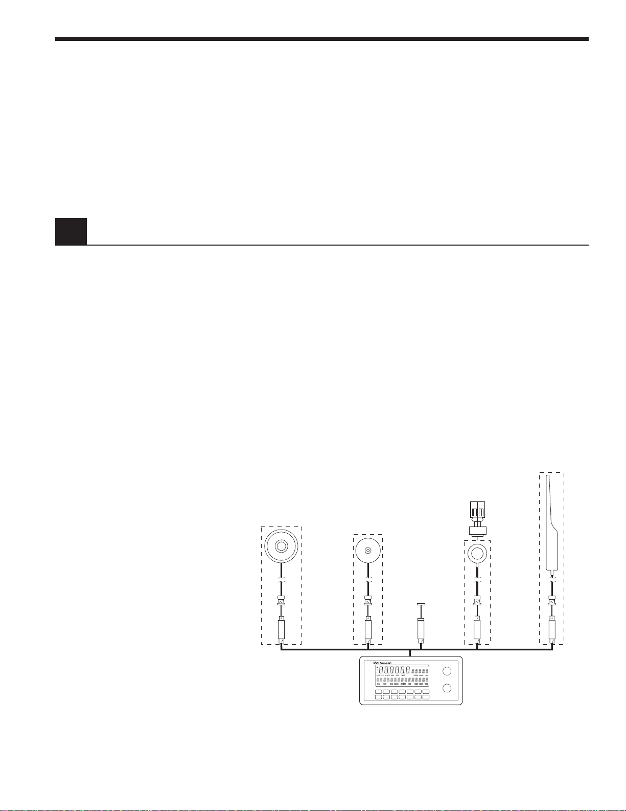
The Model 2835-C is compatible with all of Newport’s Low-Power, High-Power
and Energy detector families. A family tree of the 2835-C compatible detectors
and accessories is shown in Figure 1 below.
818T-10/CM
818T-30/CM
818T-150/CM
818T-150X/CM
818J-09/CM
818J-09B/CM
818J-25/CM
818J-25B/CM
818J-50/CM
818J-50B/CM
818-FA3-SMA
818-FA3-ST
818-FA3-FC
818-F-SL
818-F-IR
■
Multi-Function Optical Meter ■
818-UV/CM
818-SL/CM
818-IR/CM
Model 2835-C
DISP: CHA CHB
FP3-FH1
818-FA2
818-ST/CM
Figure 1 – Model 2835-C Controller and Accessories
1
Artisan Technology Group - Quality Instrumentation ... Guaranteed | (888) 88-SOURCE | www.artisantg.com
Page 18

1.2 Scope of This Manual
The Model 2835-C connects to detectors through a calibration module containing information unique to the detector being used. Calibration modules
are ordered with a detector at the time of purchase and are labeled with the
detector’s model number and serial number. Detectors with calibration
modules have a “/CM” appended to their model number.
EXAMPLE: 818-SL (no calib. module) 818-SL/CM (with calibration module)
Please carefully read this instruction manual before using the Model 2835-C
Multi-Function Optical Meter. Be especially careful to observe the warnings and
cautions throughout this manual. If any operating instructions are not clear,
contact Newport Corporation. This instruction manual contains the necessary
information for operation and maintenance of the Newport Model 2835-C MultiFunction Optical Meter as well as information for troubleshooting and obtaining
service if necessary. This information is divided into the following sections:
Section 1 General Information and Functional Description
Section 2 System Operation
Section 3 Principles of Operation
Section 4 Computer Interfacing
1.3 Unpacking and Inspection
Section 5 Remote Command Reference
Section 6 Maintenance, Test, and Troubleshooting
Section 7 Factory Service
Appendix A Syntax and Definitions
Appendix B Error Messages
Appendix C Status Reporting System
Appendix D Sample Programs
All Model 2835-C Multi-Function Optical Meters are carefully assembled,
tested and inspected before shipment. Upon receiving this instrument, check
for any obvious signs of physical damage that might have occurred during
shipment. Report any such damage to the shipping agent immediately. Retain
the original packing materials in case reshipment becomes necessary.
Artisan Technology Group - Quality Instrumentation ... Guaranteed | (888) 88-SOURCE | www.artisantg.com
2
Page 19

1.4 Preparation for Use
The Model 2835-C Multi-Function Optical Meter should have some operations
performed before measurements are made. These include:
Connecting AC Power (Section 2.5)
Detector Connection and Setup (Section 2.6)
1.5 Optional Accessories and Services
The Newport Catalog presents up-to-date information on detectors, detector
accessories and detector calibration services available for use with the Model
2835-C. Refer to Figure 1 for the Model 2835-C family tree of accessories.
Artisan Technology Group - Quality Instrumentation ... Guaranteed | (888) 88-SOURCE | www.artisantg.com
3
Page 20

Section 2
System Operation
2.1 Introduction
2.2 Display
The Model 2835-C is designed to provide quick operation and to avoid a steep
learning curve. This section starts by giving a brief listing of display, key pad
and menu command features. Much of the Model 2835-C’s operation will be
obvious after these descriptions. The manual then explains each key operation and menu command in detail. Reference each of these detailed explanations as required when getting started.
Measurement
Activity
Annunciator
Measurement
Mode
Annunciators
The Model 2835-C incorporates a vacuum fluorescent display, VFD, which can
be clearly observed with most laser goggles and at high angles of incidence.
Figure 2 illustrates and identifies the primary regions and annunciators within
the Model 2835-C’s display.
DISP: CHA CHB
PULSECONTSNGLDC INTGMODE: % P-P
MENU EDITSHIFT STORE USR CAL EXT ATTN ZERO
FILTER: ANLG + DIG
AUTO
Figure 2a – Model 2835-C VFD Display
DISP:
= CHA + CHB
Measurement Display Area
Units Display
MODE: FLTR:
= P-P DC INTG SNGL CONT PULSE
Bar Graph, Menu and Message Display Area
SHIFT MENU EDIT STORE USRCAL EXT ATTN ZERO AUTO
= ANLG + DIG
Display Channel
Annunciators
Signal Filtering
Annunciators
Status
Annunciators
Figure 2b – Description of Model 2835-C Display Regions
4
Artisan Technology Group - Quality Instrumentation ... Guaranteed | (888) 88-SOURCE | www.artisantg.com
Page 21

Table 1 – Model 2835-C Display Annunciators
Annunciator Comment
CH A The display is showing Channel A information.
CH B The display is showing Channel B information.
Blinking indicates that the meter is making
measurements.
DC Meter is set to make DC signal measurements.
INTG Meter is set to make INTEGRATED signal
measurements.
P-P Meter is set to make Peak-to-Peak signal
measurements.
SNGL Meter will make only one measurement per front
panel or external trigger.
CONT Meter will continuously make measurements until
stopped.
PULSE Meter is set to make pulse energy measurements.
ANLG Analog signal filtering is on.
2.3 Top Level Key Functions
DIG Digital signal filtering is on.
SHIFT Indicates that the next key press will execute a blue
key function.
MENU Meter and display are in menu mode. Measurement
is stopped.
STORE Meter is logging measurements into memory, i.e.
data logging.
USRCAL User (versus calibration module) has supplied the
detector responsivity in use.
EXT External trigger input is enabled.
AUTO Automatic signal gain ranging is on.
ZERO Background signal subtraction (zeroing) is on.
ATTN The responsivity in use includes the affect of the
detector’s attenuator.
Operating controls for the Model 2835-C are found on both the front and rear
panels of the Model 2835-C. For measurement operation, only the front panel
controls are used. Rear panel controls are used for AC line power setup,
Section 2.5. The front panel key pad of the Model 2835-C, Figure 3, provides
quick access to measurement functions and menu access to advanced features and setup parameters. Most of the keys on the front panel only affect
Artisan Technology Group - Quality Instrumentation ... Guaranteed | (888) 88-SOURCE | www.artisantg.com
5
Page 22

the channel indicated by the display channel annunciators. Table 2 and
Sections 2.3.1 through 2.3.21 list and describe each top level key function.
Menu level key functions are discussed in Section 2.4.
(LOCAL)
SHIFT
O I
STO REF
DISP
EXT
R/S
REF SEL
FILTER
MENU
MODE
λ
ZERO
ENTER
UNITS
RANGE
AUTO
ESC
STAT S
CH A
R/S A
CH B
R/S B
Figure 3 – Front Panel Key Pad
Table 2 – Top Level Key Functions and Associated Remote Commands
Keypad Remote Commands Description
OI
SHIFT None Enables the blue key functions.
DISP
FILTER FILTER_n, FILTER_n? Cycles signal filtering:
ZERO ZERO_n, ZERO_n?, Zeroes the display via offset subtraction.
AUTO AUTO_n, AUTO_n? Turns automatic gain ranging on and off.
CH A DISPCH, DISPCH? Selects channel A as the display channel.
None Turns the Model 2835-C on and off.
DISP, DISP? Cycles display brightness:
OFF,LOW,NORM and HIGH.
OFF, ANLG, DIG and ANLG+DIG.
STOZERO_n, ZEROVAL_n?
CH B DISPCH, DISPCH? Selects channel B as the display channel.
STO REF STOREF_n, STOREF_n? Stores last reading for future dB and
REL measurements.
REF SEL REFSEL_n, REFSEL_n? Selects the reference source to be used
for dB and REL measurements.
λ LAMBDA_n, LAMBDA_n? Displays and edits the calibration
wavelength in use.
RANGE RANGE_n, RANGE_n? Displays signal gain range in use.
, None Adjusts gain range or parameter
values or moves through a list.
R/S RUN, STOP Toggles the signal acquisition of
both channels.
MODE MODE_n, MODE_n? Cycles meter bet ween allowed
measurement modes.
UNITS UNITS_n, UNITS_n? Cycles display measurement units
between those allowed.
STATS STSIZE_n, STSIZE_n?, STMAX_n? Displays statistics.: Max, Min,
STMIN_n?, STMXMN_n? Max-Min, Mean and Std. Dev.
STMEAN_n, STSDEV_n?
R/S A RUN_A, RUN_A? Starts and stops channel A signal
acquisition.
Artisan Technology Group - Quality Instrumentation ... Guaranteed | (888) 88-SOURCE | www.artisantg.com
6
Page 23

R/S B RUN_B, RUN_B? Starts and stops channel B signal
acquisition.
EXT EXT Enable or disable external triggering.
MENU None Enter or exit MENU command mode.
ENTER None Select next lower menu level or enter
edit mode.
ESC None Escape to next higher menu level or
escape edit mode.
, None Zooms bargraph in or out. When in
Edit mode, selects the digit to be
edited by the
, keys.
Note: n in a remote command stands for A (channel A) or B (channel B).
2.3.1
OI
, Power
The OI key toggles the Model 2835-C on and off. To turn the meter on, depress
the OI key in until it clicks and stays in its depressed position. To turn the
meter off, press the key again until it clicks and rebounds to its original length.
2.3.2 SHIFT
When SHIFT is pressed, the SHIFT display annunciator lights and the blue key
functions (such as STOREF) are enabled. The next key press will cause that
blue function to be executed and the “shift status” to disable.
2.3.3 DISP , Display Brightness
This key cycles the display and the backlit key pad through: OFF, LOW, NORM
and HIGH brightness levels. This allows a user to operate in a dark environment without light pollution from the display, (except for one dim scanning
decimal point and the measurement activity annunciator).When the display is
OFF, the R/S, R/S A, or R/S B keys may be used to manually trigger measurements. Any other key press returns the display to the LOW brightness state
while ignoring the key function.
2.3.4 FILTER, Signal Filtering
Press this key to cycle input signal filtering between: OFF, ANLG, DIG,
ANLG+DIG. This function provides methods of lowering the noise observed in
the measurement data and the analog output. When the ANLG annunciator is
lit, a 5Hz low pass filter lowers the noise floor by attenuating high frequency
signal components. ANLG filtering is not available to High Power detectors,
Energy detectors or any P-P modes.
When the DIG display annunciator is lit, measurements pass through a moving
10-sample averaging buffer before being further processed, stored or communicated to the display or computer interfaces. With DIG on, all observable values
represent digitally averaged results relative to the original A/D conversions.
This averaging is independent of the subsequent processing available through
the STATS buffer, Section 2.3.15.
7
Artisan Technology Group - Quality Instrumentation ... Guaranteed | (888) 88-SOURCE | www.artisantg.com
Page 24

2.3.5 ZERO, Offset Subtraction
This key turns offset subtraction on and off. When turned on, the ZERO
annunciator lights and the last signal reading is saved as Sd and subtracted
from all subsequent signal readings S. This causes subsequent signal calculations (and the display) to use the value S-Sd instead of S.
Offset subtraction allows one to remove the effects of ambient DC signals, by
zeroing the display before making a measurement. Pressing the ZERO key a
second time turns off the ZERO annunciator and stops offset subtraction.
2.3.6 AUTO, Automatic Gain Ranging
The AUTO key toggles automatic signal ranging on and off. When on, the
AUTO annunciator lights and the signal range (amplifier gain) is adjusted to
utilize maximum analog-to-digital converter resolution. When AUTO is turned
off, the AUTO annunciator is turned off and the signal range is left in its
current state.
Signal range can be manually controlled by the , arrow keys. Pressing an
, arrow key when AUTO is on (and STATS, MENU and λ are off), turns
AUTO off and executes the manual range change. See RANGE, Section 2.3.11.
Signal range changes will often not coincide with observable changes to the
display value as the display is scaled by the detector responsivity and so must
adjust independently. Signal range gains will occur in 1 decade steps when auto
ranging and 1 or 1/2 decade steps (depending on MODE) when manual ranging.
When auto ranging in CONT PULSE mode, the arrival rate of pulses must be
above 1 Hz. In P-P CONT mode, the arrival rate of peaks must be above 50 Hz.
AUTO gain ranging is not allowed in SNGL measurement modes. When exiting
a SNGL measurement MODE, AUTO will turn back on if it was on when the
SNGL measurement mode was entered. (See MODE, Section 2.3.13)
2.3.7 CH A (B), Display Channel A (or B)
CH A causes channel A to be the display channel. CH B causes channel B to be
the display channel. The display channel annunciators will indicate which
channel is currently the display channel. When a display channel is selected,
the front panel will change to reflect its settings and measurement data.
Operations from the keypad or menu that affect a specific channel will only
affect the currently displayed channel and not the other.
2.3.8 STO REF, Store Reference Value
STO REF causes the last measurement, D, to be stored as D
use in relative measurement calculations. When units are relative, REL, and
the stored reference is selected, the displayed value is the ratio D/D
units are logarithmic relative, dB, and the stored reference is selected the
displayed value is the function 10 log (D/D
ref
). D
is always a power reading
ref
stored in the units of Watts. Press STO REF to cause a new D
existing D
value.
ref
for subsequent
ref
. When
ref
to overwrite the
ref
NOTE
When not using remote interface operation and when displaying relative dB
or REL measurements with the stored reference selected, the message
display area will show the STO REF value used in the calculation.
Artisan Technology Group - Quality Instrumentation ... Guaranteed | (888) 88-SOURCE | www.artisantg.com
8
Page 25

2.3.9 REF SEL, Select Reference
The REF SEL key is used to select the reference value, Dref, to be used for
relative, REL, and logarithmic relative, dB, unit readings. Press the REF SEL
key to display the reference source in the message display area. The EDIT
annunciator will be lit and the current selection will blink. Press , to
select a new reference source. The choices will be:
STO REF - The last stored measurement
USR REF - User defined reference (see the USRREF command in Section 5.3
Device Dependent Commands)
CH A(B) - The other channel
Press ENTER to accept the new reference source and exit the select reference
mode. Press REF SEL or ESC to exit without changing the reference source.
NOTE
The CH A(B) source is only applicable if the other channel is available. If the
other channel is not availble then N/A will appear next to CH A(B) and you
will not be able to select it.
2.3.10 λ, Wavelength
A detector calibration module contains responsivity data for its assigned
detector at discrete wavelengths. By telling the meter which wavelength is
being measured, the correct responsivity value is used in calculating the
measured power or energy. When a wavelength falls between two calibration
points, linear interpolation is used to approximate the true responsivity value.
Press the λ key to display the measurement wavelength in the message
display area. Press ENTER to light the EDIT annunciator and cause the last
digit of the wavelength to blink. Press , to adjust the blinking digit up or
down and , to change which digit blinks. Press the ENTER a second time
to accept the new wavelength and exit the wavelength edit/display mode.
Press λ or ESC to exit without changing the wavelength.
2.3.11 RANGE, Signal Range
RANGE key allows the user to view the amplifier signal range. Signal ranges
step in 1 or 1/2 decade gain increments (MODE dependent) as the RANGE is
changed in order to utilize maximum resolution from the meter’s analog-todigital converters. The available signal ranges are detector and mode dependent. Press RANGE to display the signal range number in the message display
area. If AUTO is on, then the signal range number will change if the detector signal
varies more than a decade in magnitude. Signal range changes can occur without
an effect on the displayed measurement value. Press RANGE a second time to exit
the signal range display mode.
Press the , arrow keys to increase or decrease the signal range. If AUTO
is on, pressing the , arrow keys will disable AUTO and cause the signal
range to change. Manual ranging is useful when working with external analog
recording equipment.
NOTE
Pressing the , arrow keys will disable AUTO ranging and change the signal
range even when the signal range is not being displayed via the RANGE key.
Artisan Technology Group - Quality Instrumentation ... Guaranteed | (888) 88-SOURCE | www.artisantg.com
9
Page 26

2.3.12 R/S, Run-Stop
The R/S run-stop key provides front panel control over data acquisition for both
channels simultaneously. If the channel is in SNGL measurement mode, each
R/S key press causes one reading to be taken. In CONT measurement mode, each
R/S key press toggles continuous data acquisition on and off.
The activity annunciator (Figure 2b) flashes to indicate that readings are being
taken on the displayed channel as indicated in the upper right hand corner of
the display. A steady glow indicates that the meter is armed and waiting for a
pulse or P-P waveform to arrive. The indicator is off when data acquisition on
the displayed channel has been stopped. In the special case that both channels are started together in DC CONT mode the readings will be synchronized
together with channel A readings leading channel B readings by about 70 µsec.
Otherwise the channels run independent of each other.
2.3.13 MODE, Measurement Mode
The Model 2835-C provides a number of measurement modes for acquiring
data. At power on, the meter checks the detector’s calibration module to
determine which measurement modes the detector supports. Table 3
describes the measurement modes available for each detector family.
Table 3 – Newport Detector Families and Available Measurement Modes
Low-Power High-Power Energy
DC CONT 䊉䊉
DC SNGL 䊊䊊
INTG 䊊䊊
P-P CONT 䊊
P-P SNGL 䊊
CONT PULSE 䊉
SNGL PULSE 䊊
䊉 marks the default mode for the detector family.
Press the MODE key repeatedly until the desired mode is indicated in the mode
annunciator area of the display, see Table 4. When selecting a new mode, the
display units will change to appropriate default units. See Section 2.3.14 for
more details about units.
Artisan Technology Group - Quality Instrumentation ... Guaranteed | (888) 88-SOURCE | www.artisantg.com
10
Page 27

Table 4 – Model 2835-C Measurement Modes
Mode Description
DC CONT Measurement occurs at a programmable sample rate,
Section 2.4.7.
DC SNGL A measurement is taken every time the meter receives a
trigger up to a 500Hz rate when two detector calibration
modules are plugged into the meter and 1000Hz for one.
(AUTO is disabled in SNGL mode.)
INTG Measurements occur at 400Hz and are trapezoidally
integrated to get an energy result. An R/S key press or
external trigger sets the display to 0.0000 and sampling
starts. A second R/S keypress or external trigger terminates integration.
P-P CONT Acquisition is driven by the arrival of high-low peak
pairs. A measurement is processed for every high-low
peak pair up to a frequency of 500Hz when two detector
calibration modules are plugged into the meter and
1000Hz for one. NOTE: pair captures experience a
minimum 2 or 1 ms separation respectively.
P-P SNGL A trigger1 arms the meter to capture the next high-low
peak pair. Triggers can occur at a rate of up to 500Hz
when two detector calibration modules are plugged into
the meter and 1000Hz for one. (AUTO is disabled in
SNGL mode.)
CONT PULSE The meter captures every energy pulse up to a frequency
of 500Hz when two detector calibration modules are
plugged into the meter and 1000Hz for one. Above this
rate, pulse acquisitions experience a minimum 2 or 1 ms
separation respectively.
SNGL PULSE A trigger1 arms the meter to capture the next energy
pulse. Triggers can occur at a rate of up to 500Hz when
two detector calibration modules are plugged into the
meter and 1000Hz for one. (AUTO is disabled in SNGL
mode.)
1
“Trigger” refers to a command to start or stop signal acquisition. Trigger
sources are the R/S key, the external trigger input and remote interface
commands.
2.3.14 UNITS, Display Units
Measurements can be displayed in various units. The set of units available at
any given time is determined by the detector type and the measurement
mode. Press the UNITS key repeatedly to cycle the display through the set of
available units. Table 5 describes the sets of available units for each detector
family as a function of the measurement mode.
Artisan Technology Group - Quality Instrumentation ... Guaranteed | (888) 88-SOURCE | www.artisantg.com
11
Page 28

Table 5 – Valid Display Units Available to Detector Families by MODE.
FAMILY MODE V A W W/cm
2
J J/cm2Erg Erg/cm2dBm dB REL
Low-Power DC CONT 䊊䊉䊊 䊊䊊䊊
Low-Power DC SNGL 䊊䊉䊊 䊊䊊䊊
Low-Power INTG 䊉䊊䊊䊊
Low-Power P-P CONT 䊊䊉䊊 䊊䊊䊊
Low-Power P-P SNGL 䊊䊉䊊 䊊䊊䊊
High-Power DC CONT 䊊 䊉䊊 䊊䊊䊊
High-Power DC SNGL 䊊 䊉䊊 䊊䊊䊊
High-Power INTG 䊉䊊䊊䊊
Energy CONT PULSE 䊊 䊉䊊䊊䊊 䊊
Energy SNGL PULSE 䊊 䊉䊊䊊䊊 䊊
䊉 denotes the default units for the detector family in the given measurement
mode. Some display units are abbreviated. Table 6 lists displayed units
versus actual measurement units. Display units are limited to four characters
in order to provide for display engineering prefixes such as: p, n, µ, m and k
(pico, nano, micro, milli and kilo respectively).
Table 6 – Displayed Unit Abbreviations Versus Actual Measurement Units.
Actual Units V A W J Erg W/cm2J/cm2Erg/cm2dBm dB REL
Displayed Units V A W J ERG W/cm J/cm E/cm dBm dB E±dd
2.3.15 STATS, Moving Statistics
The STATS key causes a list of statistical results from the stats buffer of the
display channel to be displayed in the message display area. The stats buffer
is a moving data window containing the most recent measurements to a depth
1 ≤ N ≤ 100. The default value is N = 10. Display occurs without disrupting
data acquisition or storage and results are continuously updated.
Press the STATS key to enter the stats display list. The first statistic displayed
will be the stats buffer depth N. Press the , adjust keys to move through
the list. The following statistics are available: N, MAX, MIN, MAX-MIN, MEAN
and STD DEV.
When the STATS buffer depth, N, is displayed, it can be adjusted by pressing
ENTER and using the , keys to set a new value for N. Press the ENTER
key to adopt the new value for N and escape the edit mode. The STATS buffer
is cleared whenever a new stats buffer depth N, or MODE or UNITS is established. Press the STATS key a second time to exit the stats display mode.
2.3.16 R/S A(B), Run-Stop Channel A (or B)
The R/S A and R/S B run-stop keys provides front panel control over data
acquisition for each individual channel. When in SNGL measurement mode,
each R/S A(B) key press causes one reading to be taken on the respective
channel. In CONT measurement mode, each R/S A(B) key press toggles
continuous data acquisition on and off on the respective channel.
12
Artisan Technology Group - Quality Instrumentation ... Guaranteed | (888) 88-SOURCE | www.artisantg.com
Page 29

The activity annunciator (Figure 2b) flashes to indicate that readings are being
taken on the display channel as indicated in the upper righthand corner of the
display. A steady glow indicates that the meter is armed and waiting for a
pulse or P-P waveform to arrive. The indicator is off when data acquisition on
the displayed channel has been stopped.
2.3.17 EXT, External Trigger
EXT enables and disables the triggering of data acquisition through the rear
panel trigger input BNC connector. The meter can be configured to be
triggered by either a rising or falling edge TTL signal. See Section 2.4.9.
Press EXT to light the EXT annunciator and enable the external trigger input to
both channels. The Model 2835-C will still respond to triggers from the R/S, R/S
A, or R/S B keys even when the EXT trigger is enabled. Press the EXT key a
second time to turn off the annunciator and disable the external trigger input.
2.3.18 MENU
The MENU key provides access to advanced features and parameters. Press
the MENU key to stop all data acquisition, light the MENU annunciator, and
display the first item of the top level menu list. Press the MENU key a second
time to immediately exit the menu. Menu structure and functions are presented in Section 2.4. The menu consists of a series of lists and parameter
values. Most parameter values can be edited to configure the meter. Lists are
moved through via the , keys. To move to a lower level list, press the
ENTER key. To escape a lower level list, press the ESC key.
In the menu, all key functions are ignored except for the MENU, ENTER, ESC
and the , keys. Each key will act without having to initially press SHIFT.
Pressing SHIFT will toggle the SHIFT annunciator, but it will not effect anything
else when in MENU mode.
To edit a displayed parameter press ENTER. This enables the edit mode and
causes the parameter (or a digit) to blink. Press the , keys to adjust the
parameter through its allowed list or to count the blinking digit up and down.
When adjusting a numerical value, the , keys can be used to change
which decimal digit blinks. Press ENTER to adopt the new value and escape
the editing mode. Press ESC to leave the editing mode without adopting the
new value.
2.3.19 ENTER
ENTER allows one to move lower into the menu when in menu mode, to enter
editing mode when an editable parameter is being displayed and to adopt a
new parameter value after it has been edited. Editable parameters can be
found both in and out of the menu mode. If ENTER is pressed when a noneditable parameter is being displayed, the key press is ignored.
2.3.20 ESC, Escape
ESC allows one to escape to the next higher level when in menu mode and to
escape editing mode when editing a parameter value without adopting any
changes to the parameter. At the top level of the menu, pressing the ESC key
exits the menu mode. The ESC key also allows one to escape various other
display modes such as STATS or wavelength display or amplifier signal gain
range display modes. When there is nothing to escape from, the ESC key is
ignored.
Artisan Technology Group - Quality Instrumentation ... Guaranteed | (888) 88-SOURCE | www.artisantg.com
13
Page 30
2.4 Menu Level Functions
2.3.21 , , , Adjust
The , , , keys allow one to adjust various parameter states and values.
In normal operation, the , keys turn AUTO off and adjust the amplifier
signal gain. In any other mode, the , keys cause one to move through a list
or to adjust a blinking digit. The , keys zoom the bargraph ( in, out)
and in edit mode, select which digit of a numerical value will blink.
Menu functions provide control over parameter values and methods of
making measurements. The menu consists of a number of lists and parameter values. Table 7 presents a quick summary of the hierarchy of the
menu functions and parameters. Most settings displayed in the menu and
changes to those settings affect the channel indicated by the display
channel annunciator.
2.4.1 Menu Access and Movement
To access the menu press MENU. The MENU annunciator will light and data
acquisition will stop. Menu labels and parameter values are displayed in the
message display area. The first, second and third leftmost decimal points
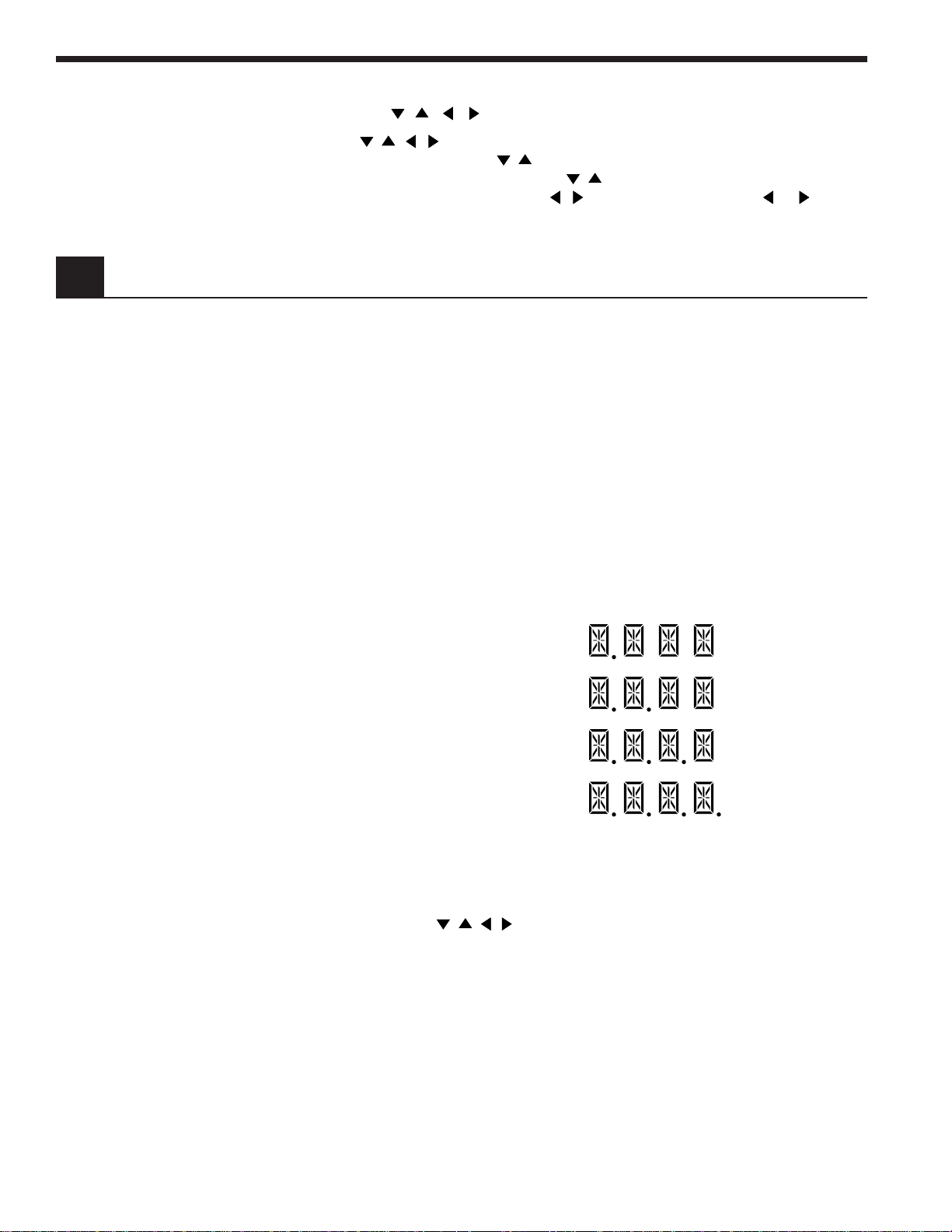
within this area indicate a current position at the top, second, third or fourth
level of the menu hierarchy, Figure 4. Table 7 presents the menu functions
and their hierarchy.
Top Level
Second Level
Third Level
Fourth Level
Figure 4 – Decimal Point Indication of Menu Hierarchy Position
In the menu, valid keys are limited to those needed to perform operations to
move through the menu or edit a parameter value. In the menu, it is not
necessary to hit the SHIFT key to invoke the action of the menu keys: MENU,
ENTER, ESC or , , , . The SHIFT key will toggle the SHIFT annunciator,
but with no effect on subsequent pressings of other keys. Once in the menu,
the rules for moving through the menu are as follows:
i. Press ENTER to move to the next level down or to enter the edit mode if a
editable parameter is being displayed and to accept a parameter value in
its currently displayed state and exit edit mode.
ii. Press ESC to move to the next level up or to escape the menu when at the
top level or to exit edit mode without changing the parameter value being
edited.
iii. Press MENU to immediately escape the menu regardless of current level
within the menu.
14
Artisan Technology Group - Quality Instrumentation ... Guaranteed | (888) 88-SOURCE | www.artisantg.com
Page 31

iv. Use the , keys to move up or down through a menu list on a given
level. Also use these keys to adjust a parameter or decimal value when in
edit mode.
v. Use the , keys to select the digit being adjusted when in edit mode.
Table 7 – Menu Level Key Functions and Parameters
Top Level Second Level Third Level
DATA STORE <- -> DATA STORE OFF <- -> DATA STORE ON, OFF
CLR DATA BUFFER
(or DATA BUFFER CLR)
SLIDE BUFFER <- -> SLIDE, FIX BUFFER
D_BUF SIZE dddd <- -> D_BUF_SIZE dddd
VIEW DATA <- -> dddd OF dddd
SAVE CONFIG <- -> SAVE TO d
RECALL CONFIG <- -> RCL DEFAULT, d
ATTENUATOR <- -> ATTN ON, OFF
AUTO CAL
DET SWITCH POS <- -> SWITCH POS S, I, L
USER CALIB <- -> USR CAL OFF <- -> USR CAL ON, OFF
USR RESP <- -> d.dddE±d A/W
PRESENT RESP <- -> d.dddE±d A/W
†
†
DC SAMPLING <- -> SAMPLE PREC <- -> PREC= 20000, 4096
CNT
SAMPLE FREQ <- -> FREQ = ddd.ddd HZ
TRIGGER OUT <- -> TRIG ON CMPLT <- -> TRIG ON CMPLT,
TRIG AT FREQ ,
TRIG ON LEVEL,
TRIG ON INTG,
TRIG OUT OFF
TRIG POLARITY <- -> TRIG ACTIVE LO, HI
TRIGGER FREQ <- -> FREQ= dddd.ddd H Z
TRIGGER LEVEL <- -> LVL= ±d.ddd E±dd W
TRIGGER INTG <- -> INTG= ±d.ddd E±dd J
EXT TRIGGER IN <- -> FALLING , RISING EDGE
BAR GRAPH ON <- -> BAR GRAPH ON, OFF
TONE OFF <- -> TONE ON, OFF
REMOTE SETUP <- -> GPIB ADDR dd <- -> GPIB ADDR dd
BAUD RATE 9600 <- -> BAUD RATE 1200,
2400, 4800, 9600, 19.2K
RS-232 ECHO OFF <- -> RS-232 ECHO ON, OFF
GENERAL INFO <- -> MODEL 2835-C
SW VERSION d.d
DETECTOR INFO <- -> MODEL xxxxxx
DET SN ddddd
ATTN SN ddddd
CAL ddMONyyyy
†
Units may be in A/W, V/W or V/J.
15
Artisan Technology Group - Quality Instrumentation ... Guaranteed | (888) 88-SOURCE | www.artisantg.com
Page 32

Items in bold italics type are editable states or decimal values. Decimals are
denoted by d. Move vertically via the , keys. Move horizontally via
ENTER and ESC.
2.4.2 Data Store
The Model 2835-C allows a user to save up to 1000 measurements for each
channel for a total of 2000 measurements. These measurements are stored in
an internal buffer for subsequent viewing or transmission over a computer
interface. A separate buffer is maintained and configured for each channel.
Data is maintained on power down, but lost when a new configuration is
loaded, Section 2.4.3, or when the buffer is cleared via the CLR DATA BUFFER
command or when data with new units is being stored.
The data store buffer operates in two ways: SLIDE or FIX. In SLIDE configuration, the buffer slides along storing the most recent measurements up to the
size of the buffer. Beyond this, as data enters the buffer, the oldest data is
pushed out and lost. In FIX configuration, data storing continues until the data
buffer is full. After this, data acquisition stops and no additional data can be
stored without first clearing the buffer via the CLR DATA BUFFER command.
DATA BUFFER CLR is displayed when the buffer is empty.
The size of the buffer is set by the D_BUF_SIZE dddd menu function. Edit the
value dddd to establish the number of data points that the buffer will hold
before dropping old data or stopping data storage.
Data storing is enabled by the user via the DATA STORE menu function. Edit
the ON, OFF condition to enable or disable data storing and the associated
STORE annunciator.
When in CONT mode, data acquisition and storage is resumed immediately
upon exiting the menus if acquisition is active as the menu is entered. When
acquisition is not active when the menu is entered, or when in SNGL or INTG
mode, data acquisition and storage requires an initiating R/S key press,
external trigger or a remote RUN command upon exiting the menu.
Buffer data can be viewed via the VIEW DATA menu command. Data are dis-played
in the measurement area while the message area displays the position within the
buffer: dddd of dddd. Use the , keys to move through the buffer data. The
value dddd = 0001 is the first, i.e. the oldest datum.
NOTE
When DATA STORE is off, CONT acquisition mode behavior defaults to the
condition where data acquisition is begun without the requirement of a
starting trigger. SNGL acquisition modes always require a trigger for each
acquisition.
Table 8 – Data Store Operations
Menu Operation Keypad Commands Associated Remote Commands
DATA STORE ON, OFF Edit ON, OFF status. DSE_n, DSE_n?
DATA BUFFER CLR or
CLR DATA BUFFER If CLR DATA BUFFER, DSCLR_n
press ENTER to clear buffer
SLIDE, FIX BUFFER Edit SLIDE, FIX BUFFER DSBUF_n, DSBUF_n?
D_BUF_SIZE dddd Edit D_BUF_SIZE dddd DSSZ_n, DSSZ_n?
VIEW DATA Press ENTER and use DS_n?, DSCNT_n?, DSUNITS_n?
, keys.
Artisan Technology Group - Quality Instrumentation ... Guaranteed | (888) 88-SOURCE | www.artisantg.com
16
Page 33

NOTE
n in a remote command stands for A (channel A) or B (channel B).
2.4.3 Meter Configuration
The Model 2835-C provides a method to save the configuration of the entire
meter and to recall that configuration for later use even if the meter has been
turned off. This is accomplished through configuration buffers maintained in
nonvolatile memory. Configuration buffers are numbered 0 to 9 with buffer 0
being a DEFAULT buffer which can only be recalled but not saved to. The
reset state of all the buffers except the default buffer is empty. Empty buffers
cannot be recalled.
A recalled configuration becomes the current configuration of the meter. Any
changes to the current configuration must be saved via SAVE CONFIG or they
will be lost when a new configuration is recalled.
The meter will not recall a configuration that is not compatible with either
detector calibration module currently plugged into the meter. Configurations
using the same model of detector are compatible while configurations using
different models of detectors are incompatible.The default configuration of
the meter depends upon the detector family. The list of configuration parameters stored in a configuration buffer as well as their default values versus
detector family are listed in Table 9 below:
Table 9 – Configuration Parameters and Default Conditions
Parameter Detector Family Default Condition
MODE Low-Power, High-Power DC CONT
Energy CONT PULSE
UNITS Low-Power, High-Power W
Energy J
λ, Lambda Lowest available
PRESENT RESP PRESENT RESP
USR CAL OFF
ATTN OFF
FILTER OFF
DC SAMPLE PREC Low-Power, High-Power 20,000 CNT
DC SAMPLE FREQ 25 Hz
AUTO ON
RANGE Lowest available
ZERO OFF
Zero Value 0.000
REF SEL STO REF
Reference Value 0.001
STATS Buffer Size 10
DET SWITCH POS Energy I,(Intermediate)
DATA STORE OFF
DATA STORE BUFFER SLIDE
Artisan Technology Group - Quality Instrumentation ... Guaranteed | (888) 88-SOURCE | www.artisantg.com
17
Page 34

Parameter Detector Family Default Condition
D_BUF_SIZE 100
Data Store Units Same as UNITS
EXT OFF
EXT TRIG IN FALLING
TRIGGER OUT TRIG ON CMPLT
TRIG OUT POL TRIG ACTIVE LO
TRIG OUT FREQ FREQ = 30 Hz
TRIG LEVEL Low-Power, High-Power LVL = 0.001 W
Energy LVL = 0.001 J
TRIG INTG LVL Low-Power, High-Power INTG = 0.001 J
BAR GRAPH ON
TONE OFF
GPIB ADDR 05
BAUD RATE 9600
RS-232 ECHO OFF
These parameters adopt the following default values at power up and are not
affected by recalling a configuration or by setting the configuration to default.
Local Lockout OFF
Display Brightness NORMAL
Table 10. below lists the menu commands effecting the saving and recalling of
meter configurations.
Table 10 – Meter Configuration Operations
Menu Operation Keypad Commands Associated Remote Commands
SAVE CONFIG Adjust SAVE TO d, *SAV
and ENTER
RECALL CONFIG Adjust RECALL d, *RCL,*RST
and ENTER
2.4.4 AUTO CAL
The AUTO CAL command causes the 2835-C to perform A/D conversions of
amplifier offset voltages (zero errors) arising from aging and temperature
effects. These conversions are then used in subtracting the appropriate error
voltage from each reading during normal operation. The 2835-C automatically
performs this procedure every time it powers up (or is reset). To achieve
stable reading at the specified accuracy, AUTO CAL should be executed for
each channel after a minimum 60 minute warm-up period from power-up.
Executing AUTO CAL with High Power (Thermopile) detectors:
1. With the detector connected to the 2835-C, remove the detector from the
radiation source and allow a minimum of 60 seconds for the detector
surface temperature to stabilize.
Artisan Technology Group - Quality Instrumentation ... Guaranteed | (888) 88-SOURCE | www.artisantg.com
18
Page 35

2. Press ENTER when AUTO CAL is displayed. The display message area will
display “ONE MOMENT”, followed by a buzzer sound indicating that AUTO
CAL is complete.
NOTE:
Although at Power up, an AUTOCAL is performed, the above method is
necessary for proper calibration when the 2835-C is used with voltage sources.
Executing AUTO CAL with Low Power (Photodiode) or Energy
detectors:
Simply press ENTER when AUTO CAL is displayed. The display message area
will display “ONE MOMENT”, followed by a buzzer sound indicating that
AUTO CAL is complete. Low Power and Energy detectors do not have to be
connected to the 2835-C or removed from the radiation source to effectively
execute AUTO CAL.
2.4.5 Attenuator
The Attenuator selects the responsivity value, Rλ, to be the value for the
detector alone or the value for the detector-with-attenuator. When ATTN is
ON the ATTN annunciator is lit and the responsivity of the detector-withattenuator is used. When ATTN is OFF, the annunciator is off and the detectoralone responsivity is used. If the detector does not have an attentuator, or if
USR CAL is on (Section 2.4.6) the ATTN setting has no effect.
2.4.6 User Calibration
The Model 2835-C allows one to create a detector responsivity which overrides the responsivities obtained from the detector’s calibration module. This
allows one to account for the effects of additional optics and filters in the
measurement path. When USR CAL is on, the USR CAL annunciator is lit and
the meter adopts the responsivity value displayed by the editable USR RESP
value. Use the PRESENT RESP function to display the current calibration
module responsivity.
The USR RESP units are the same as the PRESENT RESP units. Table 11 lists
the possible user calibration operations.
Table 11 – User Calibration Operations
Menu Operation Keypad Commands Associated Remote Commands
USR CALIB ON, OFF Edit USR CALIB USRCAL_n, USRCAL_n?
ON, OFF
USR RESP Edit d.dddE±dd A/W* USRRESP_n, USERRESP_n?
PRESENT RESP ENTER to view RESP_n?
d.dddE±dd A/W*
*Units of A/W, V/W or V/J may be displayed. These units are not editable.
NOTE
n in a remote command stands for A (channel A) or B (channel B).
Artisan Technology Group - Quality Instrumentation ... Guaranteed | (888) 88-SOURCE | www.artisantg.com
19
Page 36

2.4.7 DC Sampling
The Model 2835-C incorporates two analog-to-digital, (A/D) converters, one
with 20,000 count resolution and a second with 4096 count resolution. The
user may select which A/D will be used for both channels during DC CONT
and DC SNGL acquisition modes. All other modes use the 4096 count A/D.
The 20,000 count A/D converter can operate at sample rates up to 25 Hz.
When two detector calibration modules are plugged into the meter, the 4,096
count A/D converter can operate at sample rates up to 500 Hz. When one
detector calibration module is plugged into the meter, the 4,096 count A/D
converter can operate at sample rates up to 1000 Hz.
The SAMPLE PREC menu command, Table 12, selects which analog-to-digital
converter is used for both channels. The sampling frequency for both channels can be adjusted within the limits imposed by the SAMPLE PREC state, see
Table 13. When the SAMPLE PREC state changes, the sampling frequency
defaults to 25 Hz if the existing SAMPLE FREQ is incompatible with the new
SAMPLE PREC state. The SAMPLE FREQ and the SAMPLE PREC settings affect
both channels, not just the the display channel.
Table 12 – SAMPLE PREC States and Limits.
SAMPLE PREC A/D Accuracy Sample Frequency Range
20000 CNT 20,000 counts 0.001 Hz to 25.0 Hz
4096 CNT 4,096 counts 0.001 Hz to 500.0 Hz or 1000.0 Hz
Table 13 – DC SAMPLING Operations.
Menu Function Keypad Commands Associated Remote Commands
SAMPLE PREC Edit PREC= 20,000, SPREC, SPREC?
4096 CNT
SAMPLE FREQ Edit FREQ= SFREQ, SFREQ?
ddd.ddd HZ
2.4.8 Trigger Output
The Model 2835-C’s rear panel TTL trigger output allows it to coordinate
activities among other instruments. The trigger output can operate in several
ways: conversion complete, periodic output, comparator output and integrating comparator output. In addition, the polarity of the trigger output can be
specified.
In TRIG ON CMPLT mode, a pulse is output after each reading has been
acquired and completely processed from either channel. When acquiring on
one channel, it indicates that the 2835-C is ready to take another reading. The
width of this pulse is at least 8 µS.
In TRIG AT FREQ mode, a pulse is output at a user defined frequency or rate.
Each pulse width is at least 8 µS and the programmable frequency range of the
pulses is 0.001 Hz to 1000.0 Hz.
In TRIG ON LEVEL mode, each measurement is compared to a programmable
trigger level. The units of the trigger level always equal Watts for power
detectors or Joules for energy detectors. If a measurement is less than the
specified value, then the trigger output is inactive. If the measurement
exceeds the specified value then the trigger output becomes active. The TRIG
ON LEVEL output is a shift in level rather than a pulse.
Artisan Technology Group - Quality Instrumentation ... Guaranteed | (888) 88-SOURCE | www.artisantg.com
20
Page 37

In TRIG ON INTG mode, continuous measurements from a power detector are
integrated and compared against a programmable value. The units of the
programmable value are Joules. If the calculated integral is less than the
specified value, then the trigger output is active. If the calculated integral
exceeds the specified value, then the trigger output becomes inactive. The
TRIG ON INTG trigger is a shift in level rather than a pulse.
If both channels are sampling when this function is initiated, the time lag
between subsequent triggers is less than 700 µsec. If a R/S A or R/S B is
initiated twice, then the separation between TTL OUTPUTS is relative to the
RUN command initialization, giving a time lag up to one sample period between channel triggers (depending on sample frequency chosen).
The polarity of the trigger output is programmable as active high or active
low. If the polarity is active high then the output will idle low. If the polarity is
active low then the line will idle high.
Table 14 – TRIGGER OUT Operations.
Menu Function Keypad Commands Associated Remote Commands
TRIGGER OUT Edit TRIG ON CMPLT TRIGOUT, TRIGOUT?
TRIG AT FREQ
TRIG ON LEVEL
TRIG ON INTG
TRIG OUT OFF
TRIG POLARITY Edit ACTIVE HI, LO TRIGOUTPOL, TRIGOUTPOL?
TRIGGER FREQ Edit FREQ= ddd.ddd Hz TRIGOUTFREQ, TRIGOUTFREQ?
TRIGGER LEVEL Edit LVL= d.dddE±dd W* TRIGOUTLVL, TRIGOUTLVL?
TRIGGER INTG Edit INTG= d.dddE±dd J TRIGOUTINTG, TRIGOUTINTG?
*Displayed units may be W or J depending upon the detector in use.
2.4.9 Trigger Input
The Model 2835-C’s rear panel TTL external trigger input can be enabled or
disabled, Section 2.3.17, and have its edge polarity set. The edge polarity is
accessed via the EXT TRIGGER IN menu function and can be set to rising or
falling edge triggering.
The external trigger affects both channels and, like the R/S key, acts like an
acquisition trigger when in SNGL modes and acts like a toggled acquisition gate
when in CONT modes. In Peak-to-Peak or Pulse acquisition modes the external
trigger (and R/S key) act to enable single or continuous acquisition rather than
forcing an acquisition to occur at the moment the trigger (or keypress) occurs.
The external trigger pulse width must be ≥200 ns. In DC SNGL mode, the
delay from the trigger input going active to the start of the A/D conversion is
<80 µs. In SNGL PULSE and P-P SNGL modes, the delay from the trigger input
going active to the meter becoming armed to capture the next PULSE or P-P
pair is <70 µs.
Table 15 – EXT TRIGGER IN Operations.
Menu Function Keypad Commands Associated Remote Commands
EXT TRIGGER IN Edit RISING, EXTEDGE, EXTEDGE?, EXT,
FALLING EDGE EXT?
21
Artisan Technology Group - Quality Instrumentation ... Guaranteed | (888) 88-SOURCE | www.artisantg.com
Page 38

2.4.10 Bar Graph
A high resolution analog bar graph is provided for visual feedback when
performing optical alignment tasks. This bar graph uses the message display
area and moves from left to right with increasing display value, and reaches
full scale when the digital display reaches full scale.
The , keys can be used to zoom the bargraph in and out. Press to
zoom the bargraph into a 10x magnification which auto-centers with each
subsequent press. Press to zoom out to normal 1x magnification.
Table 16. BARGRAPH Operations.
Menu Function Keypad Commands Associated Remote Commands
BAR GRAPH Edit BARGRAPH BARGRAPH, BARGRAPH?
ON, OFF
2.4.11 Tone
The 2835-C has a speaker that can emit a short tone or tick to indicate when a
peak or pulse is detected in P-P or PULSE measurement modes for the display
channel. The audible output is enabled or disabled via the TONE menu
function. TONE is not available in INTG measurement mode.
Table 17 – TONE Operations.
Menu Function Keypad Commands Associated Remote Commands
TONE Edit TONE ON, OFF TONE, TONE?
2.4.12 Detector Switch Position
Some Newport Energy detectors have a switch that sets an electronic decay
time constant to optimize operation for various pulse repetition rates. As this
adjustment effects the responsivity of the detector, the Model 2835-C must be
informed of the detector’s switch setting. The available detector switch
settings are: SHORT, INTERMEDIATE and LONG. The 2835-C accounts for the
switch setting through the DET SWITCH POS function.
Table 18 – DET SWITCH POS Operations.
Menu Function Keypad Commands Associated Remote Commands
DET SWITCH POS Edit SWITCH POS DETSW DETSW?
S, I, L
2.4.13 Remote Setup
The Model 2835-C provides both RS-232 and IEEE-488 computer interfaces as
standard features. Each interface requires that certain parameters be set.
Remote interface setup and commands are discussed in Section 4, Computer
Interfacing.
Table 19 – REMOTE SETUP Operations.
Menu Function Keypad Commands Associated Remote Commands
GPIB ADDR dd Edit GPIB ADDR dd None
BAUD RATE dddd Edit BAUD RATE 1200, None
2400, 4800, 9600, 19.2K
RS-232 ECHO Edit RS-232 ECHO ECHO, ECHO?
ON, OFF ON, OFF
Artisan Technology Group - Quality Instrumentation ... Guaranteed | (888) 88-SOURCE | www.artisantg.com
22
Page 39

2.5 Connecting AC Power
2.4.14 General Information Functions
General information about the Model 2835-C and any attached detector can be
found using the GENERAL INFO menu functions. These functions display the
Model 2835-C software version, the detector’s model number, serial number,
associated attenuator serial number and calibration date.
Table 20 – GENERAL INFO Operations.
Menu Function Keypad Commands Associated Remote Commands
MODEL cccccccc For viewing only. DETMODEL?
SW VERSION d.d For viewing only. *IDN?
DET SN ddddd For viewing only. DETSN?
ATTN SN ddddd For viewing only. ATTNSN?
CAL ddMonyyyy For viewing only. CALDATE?
Model 2835-C can be configured to operate with line voltages over the
following ranges: 90-264 VAC, 50-60 Hz. Before turning the meter on, configure it to local voltage using the following procedure:
i. Configure the Model 2835-C’s power supply voltage selection switches to
match the nominal local voltage. See Figure 5 and Table 21.
ii. Plug an AC line power cord to the rear of the Model 2835-C and then
connect the cord with AC power.
50–60 Hz
100 V
120 V
SWITCH 1 SWITCH 2
LINE
SELECT
240 V
220 V
Figure 5 – Rear Panel Power Supply Voltage Switches in Positions with
Switch 1 set to Left and Switch 2 set to Right
Table 21 – Power Supply Voltage Switch Positions.
Switch 1 Position Switch 2 Position Nominal Local Voltage
Right Right 100 VAC
Right Left 120 VAC
Left Right 220 VAC
Left Left 240 VAC
23
Artisan Technology Group - Quality Instrumentation ... Guaranteed | (888) 88-SOURCE | www.artisantg.com
Page 40

This product is equipped with a 3 wire grounding type plug. Any inter-
ruption of the grounding connection can create an electric shock hazard.
contact your electrician to perform the necessary alterations to assure
2.6 Detector Connection and Setup
Connect the detector to its calibration module as shown, Figure 6. The
detector’s model and serial numbers should match the model and serial
numbers found on the calibration module. Insert the calibration module into
the front panel input port of the Model 2835-C. An alignment pin forces the
proper orientation of the calibration module.
WARNING
If you are unable to insert the plug into your wall plug receptacle,
that the green (green-yellow) wire is attached to earth ground.
Detector Cable BNC Calibration Module
Figure 6 – Connecting a Detector with its Calibration Module
INPUT
Plug calibration
modules into these ports.
CH B
INPUT
CH A CH B
R/S A R/S B
CH A
Figure 7 – Model 2835-C Detector Calibration Module Input Port
NOTE
If the detector being connected is a battery powered Newport Energy
Detector then be sure to configure the DET SWITCH POS menu function to
match the position of the switch on the detector, see Section 2.4.12. The
2835-C defaults to the intermediate switchposition, I.
Artisan Technology Group - Quality Instrumentation ... Guaranteed | (888) 88-SOURCE | www.artisantg.com
24
Page 41

2.7 Power Up
Turn on the Model 2835-C by depressing the front panel key until it clicks in
and remains in its depressed position. The Model 2835-C will perform a power
up self test and then configure itself to its last operating state. If the last
operating state is not compatible with one of the current detectors, the 2835-C
adopts the default configuration appropriate to this new detec-tor. If the
meter does not pass its self test or fails to respond to front pa-nel key commands, refer to Section 6, Maintenance, Test and Troubleshooting.
2.8 Performing Basic Measurements
Basic measurement techniques for using the Model 2835-C are covered in the
following sections. Refer to Table 2, Table 3 and Table 7 (pages 6, 10, and 15
respectively) for a review of the Model 2835-C’s functions and capabilities.
The following instructions assume familiarity with the meters functions. They
also include steps to incorporate background correction and assume that the
experimental setup underfills and does not saturate or damage the detector.
2.8.1 Making DC Power Measurements
The following process describes the procedure for making basic optical power
measurements while properly removing the influence of ambient light and
other drift effects.
i. Plug in a Newport Low-Power or High-Power detector via its associated
calibration module and then turn the meter on. Set MODE to DC CONT, set
AUTO on and set the measurement wavelength to the desired value.
ii. When using a Newport High-Power (thermopile) detector, execute AUTO
CAL per Section 2.4.4.
iii. Cover or otherwise block the source that you will be measuring and then
turn ZERO on.
iv. Uncover the source so it illuminates the detector and note the display value.
This reading is the optical power observed by the detector due to the source.
NOTE
The process as detailed assumes that the ambient signal is not changing
between when you zero the display and when you make your measurement.
Remember, if you can see your detector as you move around, then your
detector can see you as a changing ambient DC signal!
2.8.2 Making Peak-to-Peak Power Measurements
The following process describes the procedure for making basic optical peakto-peak power measurements.
i. Plug in a Newport Low-Power detector via its associated calibration
module and then turn the meter on. Set MODE to P-P CONT, set AUTO on
and set the measurement wavelength to the desired value.
ii. Illuminate the detector and note the display value. This reading is the
peak-to-peak optical power observed by the detector.
Artisan Technology Group - Quality Instrumentation ... Guaranteed | (888) 88-SOURCE | www.artisantg.com
25
Page 42

2.8.3 Making Pulse Energy Measurements
The following process describes the procedure for making basic optical pulse
energy measurements.
i. Plug in a Newport Energy detector via its associated calibration module
and then turn the meter on. Set MODE to CONT PULSE, set AUTO on and
also set the measurement wavelength to the desired value.
ii. Illuminate the detector and note the display value as the meter measures
each laser pulse. These readings represent the energies of the incident
laser pulses. The meter will display the last pulse energy measured until a
new pulse arrives.
2.8.4 Making a Signal Integration Measurement
The following process describes the procedure for making a basic signal
integration measurement while properly removing influence of ambient light
and other drift effects. The Model 2835-C begins and ends integration via the
arrival of a trigger signal such as is received from the R/S key.
i. Plug in a Newport Low-Power or High-Power detector via its associated
calibration module and then turn the meter on. Set MODE to DC CONT, set
AUTO on and also set the measurement wavelength to the desired value.
ii. When using a Newport High-Power (thermopile) detector, execute AUTO
CAL per Section 2.4.4.
iii. Cover or otherwise block the source that you will be measuring, turn ZERO
on and then set the MODE to INTG. As you enter the INTG mode, the
meter will begin to acquire and integrate data. The display value may
reflect the integration of noise due to ambient temperature fluctuations
(thermopile) or light fluctuations (photodiode).
iv. Uncover or trigger the source. The display value should now reflect
detector signal integration process by continuously increasing.
v. Press the R/S key to stop the integration and freeze the display value at the
final integration value.
NOTE
1. The process as described above assumes that ambient signals are not
changing between when you zero the display and when you make your
measurement.
2. The 2835-C will not integrate signals less than 10 pA. If your noise level is
greater, the ZERO command may help (step iii).
2.8.5 Measuring a Laser Pulse Energy with a Thermopile Detector
This application makes use of the Model 2835-C’s INTG mode. When an
optical pulse with energy E(λ) is incident on a thermopile, a voltage signal
arises as the heat pulse flows out to the cooling fins. The integrated signal
resulting from this heat pulse is a measure of the optical pulse energy. See
Figure 8.
Artisan Technology Group - Quality Instrumentation ... Guaranteed | (888) 88-SOURCE | www.artisantg.com
26
Page 43

Input Optical
Pulse Energy, E (λ)
E (λ)
Detector's Voltage
Pulse
Integrate Voltage
to find
E (λ)
V (t)
1
E (
λ
) =
R (
V (t) dt
∫
λ
)
Figure 8 – Measuring Laser Pulse Energy via a Thermopile in INTG Mode
A recommended procedure is:
i. Plug in a Newport High-Power detector via its associated calibration
module and then turn the meter on. Set MODE to DC CONT, set AUTO on,
set the measurement wavelength to the desired value and then execute
AUTO CAL per Section 2.4.4. Now set ZERO on and then MODE to INTG.
ii. Press the R/S key to begin the integration. Before the optical pulse arrives,
the display may reflect the integral of detector noise due to ambient
temperature fluctuations.
iii. Trigger the laser pulse and watch the display increase at a much faster
rate due to the detector signal from the heat flow.
iv. When the display increase begins to slow down and again reflect integra-
tion of the detectors noise component, press the R/S key a second time to
stop the integration. The final display value represents the pulse energy.
NOTE
If the integrated result of the pulse signal is much larger than the integral of
the detector’s noise component, the display will show a steady reading after
the pulse. If the integrated result of the pulse is not much larger, then error
in the measurement will arise due to the uncertainty generated by integration of the noise component terms.
NOTE
The time constant of a thermopile detector determines the amount of time
that one should expect to wait when making an integrated energy measurement of an optical pulse. Typically, an accurate value will be arrived at 5
time constants after the arrival of the optical pulse. Newport High-Power
detector time constants are listed in the Newport Catalog and in each
detector’s manual.
2.8.6 Using the Model 2835-C as an Exposure Controller
This application uses the INTG measurement mode along with triggering
features to configure the Model 2835-C as an exposure meter-controller. Use
the following setup and procedure:
i. Connect a BNC cable between the Model 2835-C’s trigger input and trigger
output BNC connectors. Using a T-connector, connect the trigger output
BNC to your shutter’s external control BNC.
Artisan Technology Group - Quality Instrumentation ... Guaranteed | (888) 88-SOURCE | www.artisantg.com
27
Page 44

ii. Configure the trigger output to TRIG AT INTG and set the energy level at
which you wish the exposure to stop, see Section 2.4.7. Adjust the polarity
of the trigger output to open the shutter when the trigger output is active.
iii. Set the meter to INTG mode with AUTO on and then press the R/S key to
begin the integration and open the exposure controlling shutter.
iv. The display value will increase until the INTG trigger output threshold is
crossed. At the threshold, integration will stop and the trigger output will
close the shutter. The display now shows the final integration value from
the exposure.
NOTE
You can also configure the Model 2835-C as an exposure timer-controller by
configuring the trigger output to TRIG AT FREQ and setting the trigger
frequency appropriately.
Artisan Technology Group - Quality Instrumentation ... Guaranteed | (888) 88-SOURCE | www.artisantg.com
28
Page 45

Section 3
Prog. Transimpedence
Current Amp.
Prog. Voltage
Amp.
Prog. Bandwidth
Noise Filter
Voltage
Buffers
Analog
Output
Peak
Detector
Baseline
Hold Circuit
4,096 Cnt 20,000 CntPeak - Peak &
Peak - Baseline
A/D
A/D
+
–
I
V
Input
Principles of Operation
3.1 Introduction
The Model 2835-C’s electronics adapt to a number of signal measurement
tasks: DC current or voltage, AC peak-to-peak current or pulse voltage, or
integrated DC current or voltage signals. This versatility is required to handle
the various signals that Newport’s Low-Power, High-Power and Energy
detector families generate. These detector families are based on semiconductor, thermopile and pyroelectric detectors respectively. Detector data is
introduced to the Model 2835-C by way of a calibration module specific to the
detector in use. At power up (and RESET), the 2835-C uploads information
about the detector from the calibration module which describes the set of
operating states available to the detector. A user then selects among the
available operating states when using the meter. Front panel control and the
operating states of the Model 2835-C are discussed in Sections 2.3 and 2.4.
3.2 Analog Signal Flow
Detector signals can follow many different paths through the Model 2835-C
input amplifier chain. A block diagram of analog signal flow is shown in Figure
9. The actual flow path depends upon the detector type and the mode of
measurement.
Figure 9 – Model 2835-C Analog Signal Flow Diagram
29
Artisan Technology Group - Quality Instrumentation ... Guaranteed | (888) 88-SOURCE | www.artisantg.com
Page 46

Detector Family Resp. Units Mode Amplifier Path Peak-Peak A/D Converter
Low-Power A / W DC I No 20,000 or 4,096
Low-Power A / W P-P I , AC coupled Yes 4,096
Low-Power A / W INTG I No 4,096
High-Power V / W DC V only No 20,000 or 4,096
High-Power V / W INTG V only No 4,096
Energy V / J PULSE V only Yes 4,096
3.3 Digitized Signal Flow
The analog signal flow path is primarily determined by the responsivity units
of the detector. The numerator of these units indicates how the meter must
be configured in order to obtain a calibrated optical measurement. Analog
signal flow is independent of whether SNGL or CONT measurements are made.
Responsivity units and signal flows for the various detector families are listed
in Table 22.
Table 22 – Analog Signal Flow Paths.
Signals that are captured by one of the analog-to-digital converters are further
processed as illustrated in the signal flow block diagram of Figure 10. Raw
signals are acquired by the analog-to-digital converters and have the units of
current or voltage depending upon how the input amplifier chain was configured. These digitized signals move through a number of process steps which
may or may not alter the digitized value depending upon the operating state of
the meter. Each of these possible processing steps is discussed in their order
of occurrence.
Detector
Calib.
Module
Front Panel
Figure
9
Remote
Interface
DIG
Filter
VFD
Display
Gain ZERO
Reference
STATS
Buffer
Data Store
Buffer
ZERO
Responsivity
UNITS
Figure 10 – Model 2835-C Digitized Signal Flow Block Diagram
Digital Filter
If the digital filter annunciator DIG is on, Section 2.3.4, the filter output is the
average of the most recent 10 digitized values. When less than 10 values have
been acquired since the last reset of the digital filter, the output is the average
of all the values received. The digital filter is reset when the Model 2835-C is
turned on and whenever the UNITS or the range changes or when the MODE
key is pressed.
Artisan Technology Group - Quality Instrumentation ... Guaranteed | (888) 88-SOURCE | www.artisantg.com
30
Map(s)
STO-REF
Reference
Page 47

NOTE
When using the digital filter in SNGL acquisition mode , each measurement is
the average of the last 10 acquisitions independent of how old any of the
measurements are.
Gain
Gain processing accounts for the signal gain of the input amplifiers. The
output is the product of the digitized value and the amplifier gain.
Zero Offset
Zero offset is active whenever the ZERO annunciator is lit, Section 2.3.5. The
zero offset output is equal to the input value less the zero reference value,
S-S0.
Responsivity Map(s)
This process scales the input value in accordance with current calibration
wavelength and the responsivity map downloaded from the detector calibration
module. The output of this process, i.e. the measurement value, is the digitized
input value divided by the responsivity associated with the current calibration
wavelength or the user defined calibration value. Different responsivities are
used depending upon if the attenuator, ATTN, annunciator is lit, Section 2.4.5.
3.4 Typical Detector Signals
Units Correction
Units correction adjusts a measurement value to account for the display units
selected. When the display units are equal to the detector signal units, i.e.
equal to the numerator of the responsivity units, Table 22, the measurement
value is not adjusted. Otherwise the digitized value is adjusted to account for
detector responsivity and/or additional unit conversions such as Joules-toErgs or W-to-W/cm2.
NOTE
Per area unit conversions such as W-to-W/cm2 divide the measurement value
by the active area of the detector. This calculation assumes that the entire
active area of the detector is uniformly illuminated. Per area measurements
where the entire detector active area is not uniformly lit are not accurate. The
user must insure that these conditions are met before utilizing per area units.
The flexibility of the Model 2835-C analog signal flow is required in order that
it may properly measure the signals that various types of detectors make.
Basic optical power or energy measurements are related to a measured
detector signal, S, in the following way:
S
P or E =
R
λ
Where: Rλ= Detector responsivity at λ.
= Detector signal
S
Artisan Technology Group - Quality Instrumentation ... Guaranteed | (888) 88-SOURCE | www.artisantg.com
31
Page 48

Semiconductor (Newport Low-Power) detectors provide a current signal. The
2835-C is capable of 100fA resolution in order to provide the highest sensitivity performance with these detectors.
Thermopile (Newport High-Power) detectors, provide a small voltage signal.
The 2835-C is capable of 125 nV resolution in order to reach the sensitivity
limits of thermopile detectors.
Pyroelectric (Newport Energy) detectors, deliver a peak voltage signal, . The
2835-C is capable of capturing 2 µsec rise time voltage spikes so that it may
operated with the fastest of these detectors.
3.5 Thermopile Detector Signals
Thermopile detectors respond with a voltage signal that slowly to changes in
incident optical power. The time constant of most thermopile detectors is on
the order of 1 to 10 seconds.
Input Optical Signal
3.6 Pulse Energy Detector Signals
A Newport Energy detector will respond to a single radiant energy pulse with
a voltage pulse at its BNC output. This pulse exhibits a sharp voltage rise to a
peak followed by a slower voltage decay which “undershoots” zero volts
before settling back to zero volts. When a detector is operated within its
proper limits, the voltage difference from immediately before the sharp rise to
the peak is linearly proportional to the radiant energy.
If a second pulse arrives before the “undershoot” rises back to zero volts, the
voltage rise from this pulse will start from an initial negative value. At sufficient
energy pulse repetition rates, a negative “baseline” voltage will develop from
which the voltage rise must now be measured to achieve accurate energy
readings. The 2835-C contains baseline capture circuitry which maintain its
accuracy specifications over rep-rates ranging from single pulse to 2 Khz.
Thermopile
Response
Displayed Signal
1 sec 5 sec
Figure 11 – Thermopile Signals exhibit 1 to 10 second time constants.
Artisan Technology Group - Quality Instrumentation ... Guaranteed | (888) 88-SOURCE | www.artisantg.com
32
Page 49

1.0
0.8
0.6
VOLTS
0.4
0.2
0.0
0.00 0.02 0.04 0.06 0.08 0.10
V
peak
TIME (sec)
Figure 12 – Typical Newport Energy Detector Signal Waveform - An energy
detector signal sharply rises to a peak value and then decays going somewhat negative before finally returning to zero. The energy in the radiant
pulse is proportional to the height of the peak measured from immediately
before the sharp rise.
1.0
0.8
0.6
VOLTS
0.4
V
peak
0.2
0.0
0.0 0.2 0.4 0.6 0.8 1.0
Figure 13 – Negative Baseline Voltage Due to a Pulse Train - If a laser pulse
arrives before the previous Energy detector signal has fully decayed, the
detector signal rises from the present decay point of the previous signal.
3.7 Peak-to-Peak (Photodiode) Detector Signals
The Model 2835-C allows one to make peak-to-peak measurements of time
varying signals from semiconductor photodiode detectors. Since optical
power is a zero bounded positive quantity, signals from a detector observing
such modulated light will similarly be zero bounded positive signals. To make
a peak-to-peak measurement, the Model 2835-C must be able to capture both
the maximum and minimum values of a detector signal. This is accomplished
by AC coupling the incoming detector signal so that the original minimum
value shows up as a negative peak.
TIME (sec)
Artisan Technology Group - Quality Instrumentation ... Guaranteed | (888) 88-SOURCE | www.artisantg.com
33
Page 50

DC Average
AC Peak-to-Peak
DC + AC Peak
The Model 2835-C can only measure periodic AC peak-to-peak signals within
the frequency range: 50 - 7,000 Hz. Above 7,000 Hz, bandwidth limitations
significantly effect the accuracy of the peak-to-peak measurement. Below 50
Hz, the AC coupling attenuates signals and measurement accuracy. However,
low frequency measurements can be quantified in DC CONT measurement
mode, see note below.
Peak-to-peak measurements of frequencies below 50 Hz can be accomplished
by observing the MAX-MIN value of the STATS buffer in DC CONT measurement mode, Sections 2.3.13 and 2.3.15. To do so, disable the analog filter,
adjust the sample rate, Section 2.4.7 and the STATS buffer depth, Section
2.3.15, so that the actual maximum and minimum values will be captured by
the stream of DC measurements.
3.8 Integration of Detector Signals
The Model 2835-C provides for making measurements that integrate incoming
power detector signals to obtain an energy via the INTG mode, Section 2.3.13.
In INTG mode, the display units indicate Joules since energy is the time
integral of power:
Figure 14 – Time Varying Signal Measurements - Many different measurements can be made on different portions of a time varying signal. The most
common are: DC power, peak power, and peak-to-peak power.
NOTE
t
1
EPdt
λλ
()=()
∫∫
t
0
t
1
St
()
R
t
0
dt
λ
()
=
As the detector signal actually consists of a stream of digitized values, the
integral becomes a numerical approximation using the trapezoid method,
Figure 15. In order to maintain the highest accuracy for this numerical
process, the sample rate is set at its maximum value of 400 Hz.
34
Artisan Technology Group - Quality Instrumentation ... Guaranteed | (888) 88-SOURCE | www.artisantg.com
Page 51

Detector Signal
Numerical Integration
Trapezoid Method
Magnitude of the
Integrated Result
Figure 15 – Integrated Energy Via a Trapezoid Approximation - The INTG
measurement mode performs a discrete integration at a 400 Hz sample rate.
Two common applications are natural extensions of the INTG measurement
mode:
1. Pulse laser energy measurement using with a thermopile detector, Section 3.5
2. Energy from exposure over a period of time (dosage), Section 3.6.
3.9 Analog Output
Input Optical
Pulse Energy, E (λ)
Detector's Voltage
Pulse
Integrate Voltage
to find
E (λ)
E (λ)
V (t)
1
E (
λ
) =
R (
V (t) dt
∫
λ
)
Figure 16. Measuring Laser Pulse Energy with a Thermopile - Thermopiles
are often used to measure pulsed laser energy by integrating the response of
the detector to the pulse.
The Model 2835-C provides a 0 to 2.5 volt, into 50W,BNC analog output for
signal monitoring. The analog output is the actual amplified detector signal
and is uncorrected for the effects of the detector’s responsivity, AUTO CAL,
and ZERO.
Artisan Technology Group - Quality Instrumentation ... Guaranteed | (888) 88-SOURCE | www.artisantg.com
35
Page 52

3.10 Measurement Considerations
This section describes detector characteristics, optical and electrical considerations, and environmental influences on optical measurements. In general,
measurement accuracy is limited by the accuracy of the detector calibration.
Accurate measurements, however, are also dependent upon proper set-up,
control of temperature and illumination conditions and understanding the
factors that affect optical measurements.
3.10.1 Detector Calibration and Accuracy
Newport Corporation calibrates its detectors using secondary standards
directly traceable to the United States National Institute of Science and
Technology (NIST) or to Great Britain’s National Physical Laboratory (NPL).
The details and accuracy of the calibration procedure vary with each detector
model but a detailed description of the calibration results is supplied with
each individually calibrated detector. In general, detector calibration accuracy varies from 2% to 5% in absolute terms and varies with wavelength. Each
detector will also have some variation in response over its surface. Therefore,
for the most reproducible measurements, light should illuminate the detector
as uniformly as possible over as large an area as practical.
CAUTION
Avoid focusing a light source onto the detector surface. Inaccurate
readings and possible detector damage may result. Consult the detector
manual for saturation or damage thresholds.
NIST traceability requires that detectors be recalibrated on one year intervals.
As individual detector responses change with time, especially in the ultraviolet, recalibration is necessary to assure confidence in the accuracy of the
measurement. For the most reproducible measurements, the same detector
should always be used for measurements which are to be directly compared.
3.10.2 Quantum Detector Temperature Effects
Semiconductor (Newport Low-Power) detectors, are affected by temperature.
At long wavelengths, quantum detectors typically lose sensitivity with increasing temperature. Additionally, detector dark current increases exponentially
with temperature.
Observed dark current is often dominated by the interaction between the
detector and a meter’s amplifier and is typically larger than the theoretical
dark current limit. Silicon detectors are inherently quieter than germanium
detectors due to their higher internal resistance and lower capacitance. The
noise or drift in the dark current sets a lower bound on the measurement
resolution which can be achieved with any given detector. Cooling a detector
significantly lowers its dark current and dark current noise.
The observed dark currents can also be zeroed at any moment via the ZERO
function. Since dark currents drift with temperature, the ZERO should be
adjusted just prior to taking any measurements. If the detector temperature is
constant, sensitivity changes and dark current drifts are significantly reduced.
Artisan Technology Group - Quality Instrumentation ... Guaranteed | (888) 88-SOURCE | www.artisantg.com
36
Page 53

3.10.3 Thermopile Detector Temperature Effects
Thermopile (Newport High-Power) detectors are significantly affected by
temperature fluctuations arising from air flow disturbances. As the detector is
a temperature measuring device, air flow disturbances set a practical lower
limit on the power that a detector can measure. In order to get the most out
of any thermopile detector, be careful to shield the detector from air flow
disturbances. Common sources of disturbance are: air conditioners and
people walking past.
3.10.4 Energy Detector Temperature Effects
Pyroelectric (Newport Energy) detectors are AC coupled devices and thus are
not susceptible to temperature induced DC signal offsets or noise floor changes.
One generally does not need to take much precaution with pyroelectric detectors except to make sure that their damage threshold is not exceeded.
3.10.5 Ambient and Stray Light
Ambient and stray light striking the detector should be considered when
making a measurement. Ambient light can be distinguished from dark current
(or the detector/meter noise floor) by either turning off or blocking the source
and covering the detector face with opaque material such as a piece of black
rubber.
Using the human hand to cover the detector is not advised because it emits a
significant amount of infrared radiation and radiates a temperature significantly different from ambient. With the detector covered, a reading of the
dark current may be made. Next, remove the material which is covering the
detector and take another reading. The difference is the ambient light level.
NOTE
Changes in ambient light levels can occur from such factors as turning room
lights on or off, or by moving people or equipment. Remember, if you can see
your detector element, then your detector can see the light bouncing off you.
The effects of ambient light are greatly reduced when using a fiber-connectorized
signal input to the detector. If free-space beam measurements are desired,
using an attenuator will often improve the signal to ambient signal noise level.
Wavelength-specific filters, such as optical cutoff, bandpass, or spike filters
can be used if the signal wavelength spectrum permits. Other techniques to
reduce stray light include using apertures, placing the detector in a box or
other housing to shield the surface from light (or air currents) and turning off
room and other polluting light sources.
Artisan Technology Group - Quality Instrumentation ... Guaranteed | (888) 88-SOURCE | www.artisantg.com
37
Page 54

3.10.6 Common Measurement Errors
The most common sources of optical measurement error are listed in Table 23
below. Other common errors are discussed in the preceding subsections of
Section 3.10, Measurement Considerations.
Table 23 – Common Measurement Errors
Type of Error What should be done?
Radiometry Check that all of the light is actually hitting
the detector.
Ambient Light Check that any ambient light was ZEROed
before the measurement was made.
Wavelength Calibration Check that the Calibration Factor for the
measurement wavelength is properly set.
Detector Saturation Check that the optical power density remains
or Damage below the detector’s saturation or damage
threshold.
NOTE
The Model 2835-C will indicate when a detector is being operated above its
saturation or damage threshold by displaying “SA” in the measurement
display area. Be aware that detectors often experience local saturation or
damage without ever exceeding an overall saturation or damage threshold.
This only applies to semiconductor photodiodes and thermopiles used above
maximum intermittent power.
Detector damage can still arise even when “SA” is not displayed. Be sure to
follow your detector manual’s user guidelines.
Artisan Technology Group - Quality Instrumentation ... Guaranteed | (888) 88-SOURCE | www.artisantg.com
38
Page 55

Section 4
Computer Interfacing
4.1 General Guidelines
The 2835-C has two computer interface ports: GPIB and RS-232C. The GPIB
port conforms with the IEEE Standard 488.1 hardware standard and the IEEE
488.2 software standard. The protocol for the RS-232C port conforms as much
as possible to the IEEE 488.2 software standard.
As specified by the IEEE 488.2 standard, there are two command types; device
independent commands and device dependent commands. The device
independent commands have the same meaning to all devices and are defined
as part of the IEEE 488.2 standard. All device independent commands start
with an asterisk (*). Device dependent commands do not start with an
asterisk and have meanings unique to the Model 2835-C. A query is a command that invokes a response from the meter. All queries are terminated by a
question mark (?). It is recommended that when a query is made, that the
response to that query be read before other commands are issued. When a
query is made to the GPIB interface, the MAV bit in the status byte should be
checked by means of a serial poll to make sure that the data is available
before reading the response. (See Appendix C.4 Status Byte)
4.2 Computer Interface Terminology
Listed below are key abbreviations and concepts used in the command
reference section of this manual.
<...> Delimiting Punctuation
For the purposes of this manual, any string enclosed by <....> is considered to
be a command, a string or a numerical argument. The punctuation <....> is
used to symbolize the typographic limits of the command, string or argument
in question.
<EOI> End or Identify
An IEEE 488.1 signal sometimes sent with the end-of-string character.
<IST> Individual Status
This status is generated by the status byte and parallel poll enable register. It
is used in responding to parallel polls.
Artisan Technology Group - Quality Instrumentation ... Guaranteed | (888) 88-SOURCE | www.artisantg.com
39
Page 56

<CR> Carriage Return
The ASCII encoded byte 13 in decimal. (0D hex)
<LF> Line Feed
The ASCII encoded byte 10 in decimal. (0A hex)
<NL> New Line
Defined in the IEEE 488.2 standard as the ASCII encoded byte 10 in decimal.
(0A hex)
<END> End of Message
Indicates the concurrent transmission of <EOI> with the a <NL> data byte.
(;) Semicolons
Used to separate commands within a single transmission
(concatenation).
<number> Numerical Types
Numerical parameters are passed and returned as the actual ASCII characters
in the string representation of the number. See the appendix for a detailed
description of <number>.
<string> String Types
See the appendix for a detailed description of <string>
RS-232C Command Termination
When a command is received from the RS-232C port,
either a <CR> or a <LF> is treated as the command terminator.
GPIB Command Termination
When a command is received from the GPIB port, either an <EOI> with a data
byte, <NL>, or <CR> is treated as the command terminator. The recommended form of termination is an <EOI> sent with a <NL> denoted as <END> in
this manual.
RS-232C Response Termination
In RS-232C echo mode responses are terminated by a <CR><LF> sequence. In
RS-232C normal mode the <NL> character terminates the response.
GPIB Response Termination
All responses from the 2835-C GPIB port are terminated by an <END> sequence. Which is the concurrent transmission of <EOI> with a <NL> data byte.
Artisan Technology Group - Quality Instrumentation ... Guaranteed | (888) 88-SOURCE | www.artisantg.com
40
Page 57

4.3 Entering Remote Computer Interface Mode
When a command or query is received by the GPIB or RS-232 interface ports,
the 2835-C automatically goes into remote interface mode. The message area
on the display will indicate which remote port received the command.
While in remote mode, the keypad is disabled except for the power and
<(LOCAL)> key. To get out of remote mode press the <(LOCAL)> key. If the
2835-C is in local lockout then the LLO remote command must be used to
disable local lockout before you will be able to return to keypad control.
The message area of the display will indicate when the keypad is in locallock
out state.
4.4 RS-232C Communication
Before communicating with the 2835-C through the RS-232 port, proper cable
connections must be made. Figure 17 shows the cable connections for
communicating with the RS-232C port on the 2835-C.
Once cable connections are made, the baud rate and echo mode need to be
set. Valid baud rates are 19.2K, 9600, 4800, 2400, and 1200. The parity, data
bits, and stop bits are fixed at no parity, 8 data bits, and 1 stop bit.
RS-232C Parameters
Baud Rate 19.2K, 9600, 4800, 2400, or 1200
Parity none
Data bits 8
Stop bits 1
When the echo mode is enabled the 2835-C generates a ‘> ‘ prompt for every
new line and all characters sent to the 2835-C are echoed back over the
interface. Error messages are reported over the interface immediately. As the
user is entering commands the line may be edited by using the backspace key
(sending an ASCII decimal 08 code) or by using the DEL key (sending an ASCII
decimal 127 code).
In echo mode the RS-232C port is interactive and especially useful when a
dumb terminal type of device is used to communicate with the 2835-C.
When echo mode is disabled (normal mode) the 2835-C does not generate a
prompt or echo characters back over the interface. Error messages must be
accessed by using the *ERR? query. This is the default state of the echo mode.
Artisan Technology Group - Quality Instrumentation ... Guaranteed | (888) 88-SOURCE | www.artisantg.com
41
Page 58

TO 2835 TO COMPUTER
CABLE TERMINATORS (RS-232)
9 pin to 25 pin
9 PIN
PIN NO.
TO 2835 TO COMPUTER
CODE DESCRIPTION
1
DCD
2
RXD
3
TXD
4
DTR
5
GND
6
DSR
7
RTS
8
CTS
9
CARRIER DETECT
RECEIVE DATA
TRANSMIT DATA
DATA TERM. READY
SIGNAL GROUND
DATA SET READY
REQUEST TO SEND
CLEAR TO SEND
RI
RING IND.
25 PIN
PIN NO.
8
3
2
20
7
6
4
5
22
CABLE TERMINATORS (RS-232)
9 pin to 9 pin
9 PIN
PIN NO.
1
2
3
4
5
6
7
8
9
CODE DESCRIPTION
DCD
RXD
TXD
DTR
GND
DSR
RTS
CTS
CARRIER DETECT
RECEIVE DATA
TRANSMIT DATA
DATA TERM. READY
SIGNAL GROUND
DATA SET READY
REQUEST TO SEND
CLEAR TO SEND
RI
RING IND.
9 PIN
PIN NO.
1
2
3
4
5
6
7
8
9
Figure 17 – RS-232 Cable Connections
4.4.1 Setting Baud Rate and Echo Mode From The Keypad
The baud rate and echo mode are set from within the menu structure. To set
the baud rate select the BAUD RATE option from the REMOTE SETUP menu.
To set the echo mode select the ECHO MODE_n option from the REMOTE
SETUP menu. (See Section 2.4.13)
4.4.2 Setting Baud Rate and Echo Mode From A Remote Interface
The baud rate cannot be set from the remote interface. To set the echo mode
use the ECHO command. Use the ECHO? to see if the echo mode is enabled or
disabled. (See Section 2.4.12)
Artisan Technology Group - Quality Instrumentation ... Guaranteed | (888) 88-SOURCE | www.artisantg.com
42
Page 59

4.5 RS-232C XON/XOFF Handshaking Protocol
The 2835-C uses the XON/XOFF handshaking protocol.When the 2835-C’s RS-232
input buffer is nearly full the 2835-C will send an XOFF (ASCII encoded 19
decimal) character to the remote computer. The XOFF character informs the
remote computer that it needs to suspend transmission until it receives the
XON character from the 2835-C. When the buffer empties sufficiently the 2835-C
will send an XON (ASCII encoded 17 decimal) to signal the remote computer
that it can resume transmission.
The 2835-C will also respond to XOFF and XON characters sent to it from the
remote computer. When the 2835-C receives an XOFF character it will suspend all transmission of characters to the remote computer until the XON
character is received.
4.6 GPIB Communication
A variety of third party GPIB communication hardware and software, such as
plug-in GPIB computer boards and Lab View software from National Instruments exists. The 2835-C should work with any of these as long as they
adhere to the IEEE 488.1 standard. This manual assumes the user is familiar
with one of these third party hardware/software packages. The table below
summarizes the IEEE 488.1 capabilities supported by the 2835-C.
Table 24 – Model 2835-C IEEE 488.1 Capabilities Summary
Description Command Level of Capability
Source Handshake SH1 complete capability
Acceptor Handshake AH1 complete capability
Talker T6 basic talker, serial poll, unaddress if MLA
Extended Talker TE0 no capability
Listener L4 basic listener, unaddress if MTA
Extended Listener LE0 no capability
Service Request SR1 complete capability
Remote Local RL0 *no capability
Parallel Poll PP1 remote configuration
Device Clear DC1 complete capability
Device Trigger DT0 no capability
Controller C0 no capability
NOTE
* In order to better handle the RS-232C interface the 2835-C automatically
goes into remote mode when a command is received from either of the
remote computer interfaces. The LLO command is used to enable or disable
the local lockout state.
4.6.1 Setting The GPIB Address
Before communicating with the 2835-C GPIB port the 2835-C GPIB address
must be set. The address can bebetween 0 and 30. The address can only be
set from the keypad and is accessed through the menu structure. To set the
GPIB address select the REMOTE SETUP->GPIB ADDRESS option in the menu.
The Model 2835-C GPIB is factory set to 5. (See Section 2.4.13)
Artisan Technology Group - Quality Instrumentation ... Guaranteed | (888) 88-SOURCE | www.artisantg.com
43
Page 60

Section 5
Command Reference
5.1 Model 2835-C Remote Interface Commands
The Model 2835-C remote commands can be divided into two groupings:
i. Device Independent Commands, Section 5.2
ii. Device Dependent Commands., Section 5.3
Table 25 lists the Device Independent Commands supported by the 2835-C
while Table 26 lists the Device Dependent Commands supported the 2835-C.
Following these tables are the detailed presentations of each command and its
syntax and an example of its use.
Table 25 – Device Independent Status Commands
Command Command Name
*CAL? Calibration Query
*CLS Clear Status
*ERR? Error Query
*ESE Event Status Enable
*ESE? Event Status Enable Query
*ESR? Event Status Register Query
*IDN? Identification Query
*IST? Individual Status Query
*OPC Signal When Operation Complete
*OPC? Operation Complete Query
*PRE Parallel Poll Enable
*PRE? Parallel Poll Enable Query
*RCL Recall Device Configuration
*RST Software Reset
*SAV Save Device Configuration
*SRE Service Request Enable
*SRE? Service Request Enable Query
*STB? Status Byte
*TST? System Test
*WAI Wait To Continue
Artisan Technology Group - Quality Instrumentation ... Guaranteed | (888) 88-SOURCE | www.artisantg.com
44
Page 61

Table 26 – Device Dependent Commands
Command Command Name
ATTN_n Attenuator Calibration Data Enable
ATTN_n? Attenuator Calibration Data Enable Query
ATTNSN_n? Attenuator Serial Number Query
AUTO_n Auto Ranging Enable
AUTO_n? Auto Ranging Enable Query
BARGRAPH Bar Graph Enable
BARGRAPH? Bar Graph Enable Query
CALDATE_n? Calibration Date Query
CH? Available Channel Query
DETMODEL_n? Detector Mode Query
DETSN_n? Detector Serial Number Query
DETSW_n Detector Switch Select
DETSW_n? Detector Switch Query
DISP Display Brightness Select
DISP? Display Brightness Query
DISPCH Display Channel Select
DISPCH? Display Channel Query
DS_n? Data Store Value Query
DSBUF_n Data Store Buffer Behavior Select
DSBUF_n? Data Store Buffer Behavior Query
DSCLR_n Data Store Clear
DSCNT_n? Data Store Value Count Query
DSE_n Data Store Enable
DSE_n? Data Store Enable Query
DSSIZE_n Data Store Buffer Size Select
DSSIZE_n? Data Store Buffer Size Query
DSUNITS_n? Data Store Units Query
ECHO RS-232 Echo Mode Enable
ECHO? RS-232 Echo Mode Enable Query
EVENT? Device Event Register Query
EVENTEN Device Event Enable Register
EVENTEN? Device Event Enable Register Query
EXT External Trigger Enable
EXT? External Trigger Enable Query
EXTEDGE External Trigger Edge Select
EXTEDGE? Exter nal Trigger Edge Query
FILTER_n Fi lter Select
FILTER_n? Filter Query
LAMBDA_n Lambda Select
LAMBDA_n? Lambda Query
LLO Local Lockout Enable
LLO? Local Lockout Enable Query
MODE_n Acquisition Mode Select
MODE_n? Acquisition Mode Query
R? Read Both Channel Measurements Query
R_n? Read Single Channel Measurement Query
RANGE_n Manual Range Level Select
RANGE_n? Manual Range Level Query
REFSEL_n Reference Source Select
REFSEL_n? Reference Source Query
RESP_n? Responsivity Query
RUN Start Both Channel Acquisition
RUN_n Start Single Channel Acquisition
RWS? Read Both Channel Measurements with Status Query
RWS_n? Read Single Measurement with Status Query
Artisan Technology Group - Quality Instrumentation ... Guaranteed | (888) 88-SOURCE | www.artisantg.com
45
Page 62

SFREQ DC Sample Frequency Select
SFREQ? DC Sample Frequency Query
SPREC DC Sample Type Select
SPREC? DC Sample Type Query
STMAX_n? Statistics Buffer Maximum Value Query
STMEAN_n? Statistics Buffer Mean Value Query
STMIN_n? Statistics Buffer Minimum Value Query
STMXMN_n? Statistics Buffer Maximum-Minimum Value Query
STSDEV_n? Statistics Buffer Standard Deviation Query
STSIZE_n Statistics Buffer Size Select
STSIZE_n? Statistics Buffer Size Query
STOP Stop Both Channel Acquisition
STOP_n Stop Single Channel Acquisition
STOREF_n Store Reference Reading
STOREF_n? Store Reference Query Reading
STOZERO_n Store Zero Signal
TONE Tone Enable
TONE? Tone Enable Query
TRIGOUT Trigger Out Mode Select
TRIGOUT? Trigger Out Mode Query
TRIGOUTFREQ Trigger Out Frequency Select
TRIGOUTFREQ? Trigger Out Frequency Query
TRIGOUTINTG Trigger Out Integration Level Select
TRIGOUTINTG? Trigger Out Integration Level Query
TRIGOUTLVL Trigger Out Level Select
TRIGOUTLVL? Trigger Out Level Query
TRIGOUTPOL Trigger Out Polarity Select
TRIGOUTPOL? Trigger Out Polarity Query
UNITS_n Units Select
UNITS_n? Units Query
USRCAL_n User Calibration Enable
USRCAL_n? User Calibration Enable Query
USRREF_n User Defined Reference Value Select
USRREF_n? User Defined Reference Value Query
USRRESP_n User Responsivity Factor Select
USRRESP_n? User Responsivity Factor Query
ZERO_n Signal Zeroing Enable
ZERO_n? Signal Zeroing Enable Query
ZEROVAL_n? Zero Signal Query
n stands for A (channel A) or B (channel B).
5.2 Device Independent Commands
*CAL?
Calibration Query
Syntax: *CAL?
Parameters: None
Artisan Technology Group - Quality Instrumentation ... Guaranteed | (888) 88-SOURCE | www.artisantg.com
NOTE:
46
Page 63

Function:
This routine performs an auto calibration sequence on both channels. The
calibration sequence measures the amplifier offsets at all gain settings. These
measurements are stored and subtracted from subsequent measurements.
Acquisition is suspended during auto calibration and no other remote commands will be processed until the auto calibration sequence is complete.
Returns: <number>
<number> represents the integer 0. This return value is generated when
autocalibration is complete.
Related Commands: None
*CLS
Clear Status
Syntax: *CLS
Parameters: None
Function:
This command clears the Standard Event Status register, device event register, and the error queue. As a result of this command the status byte is
cleared except for the message available bit (bit 4). Because this command
does not clear the input and output buffers the MAV bit will not be affected.
The *CLS command also cancels any outstanding *OPC and OPC? commands.
Related Commands: *ESR?, EVENT?, *IST?, *STB?
*ERR?
Error Query
Syntax: *ERR?
Parameters: None
Function:
Returns (and removes) oldest error message from the error queue. The error
message is made up of an error code and a text description of the error (see
the Appendix B). A maximum of 10 errors can be stored in the queue. If no
errors are stored in the queue, a message to that effect will be returned.
Errors that occur due to commands and queries sent from the RS-232 interface will be stored in the queue only if the echo mode is disabled. When the
echo mode is enabled the error mes-sages are automatically returned to the
user when the error occurs. See Appendix B for a description of the error
messages. The command *CLS will clear the error queue.
Returns: <errno>,<description>
<errno> is of type <number> and represents a negative integer error code.
<description> is of type <string> in double quote format, and describes the
error. See the appendix for a list of possible error messages.
Related Commands: *CLS, *STB?
Artisan Technology Group - Quality Instrumentation ... Guaranteed | (888) 88-SOURCE | www.artisantg.com
47
Page 64

*ESE
Event Status Enable
Syntax: *ESE <mask>
Parameters:
<mask> is an integer in the range 0 to 255 inclusive.
<mask> is written to the Event Status Enable register.
Function:
The Event Status Enable register is AND’ed with the Event Status register. If
any bit is set in the result of this AND’ing operation the ESB bit (bit 5) of the
Status Byte will be set. The Status Byte can be used in conjunction with the
Service Request Enable register to generate a service request.
The Event Status Enable register is an 8 bit, bit mapped register. Any bit set to
1 in the Event Status Enable Register allows the corresponding bit in the Event
Status Register to set the ESB bit (bit 5) in the Status Byte. Any bit set to 0
disables the corresponding bit in the Event Status Register from setting the
ESB bit. The Event Status Enable register is set to 0 upon power-up. See
Appendix C for a detailed description of the Event Status Register.
The significance of each bit in the Event Status Enable register is shown
below:
01234567
Operation Complete Mask
Request Control Mask (Not Used)
Query Error Mask
Device Error Mask
Execution Error Mask
Command Error Mask
User Request Mask (Not Used)
Power On Mask (Not Used)
Event Status Enable Register
Related Commands: *CLS, *ESE?, *ESR?, EVENT?,
EVENTEN, EVENTEN?, *IST?, *PRE, *PRE?, *SRE, *SRE?, *STB?
*ESE?
Event Status Enable Query
Syntax: *ESE?
Parameters: None
Function:
This query returns the contents of the Event Status Enable register. See the
*ESE command for a description of the Event Status Enable register. See
Appendix C for a detailed description of the Event Status Register.
Returns: <mask>
<mask> is of type <number> and represents an unsigned integer in the range 0
to 255.
Related Commands: *CLS, *ESE, *ESR?, EVENT?, EVENTEN, EVENTEN?,
*IST?, *PRE, *PRE?, *SRE, *SRE?, *STB?
Artisan Technology Group - Quality Instrumentation ... Guaranteed | (888) 88-SOURCE | www.artisantg.com
48
Page 65

*ESR?
Event Status Register Query
Syntax: *ESR?
Parameters: None
Function:
This query returns the contents of the Event Status Register and clears the
Event Status Register except for bit 3. Bit 3 is determined by the state of the
Device Event and Device Event Enable registers. The *CLS command will also
set this register to 0.
The Event Status register is AND’ed with the Event Status Enable register. If
any bit is set in the result of this AND’ing operation the ESB bit (bit 5) of the
Status Byte will be set. The Status Byte can be used in conjunction with the
Service Request Enable register to generate a service request. See Appendix C
for a detailed explanation of the Event Status Register.
The Event Status Register is an 8 bit, bit mapped register, with each bit
signifying a different condition. The bits are listed below, most significant bit
first:
01234567
Operation Complete
Request Control (Not Used)
Query Error
Device Error
Execution Error
Command Error
User Request (Not Used)
Power On (Not Used)
Standard Event Status Register
Returns: <value>
<value> is of type <number> and represents an unsigned integer in the range 0
to 255.
Related Commands: *CLS, *ESE, *ESE?, EVENT, EVENTEN, EVENTEN?, *IST?,
*PRE, *PRE?, *SRE, *SRE?, *STB?
Artisan Technology Group - Quality Instrumentation ... Guaranteed | (888) 88-SOURCE | www.artisantg.com
49
Page 66

*IDN?
Identification Query
Syntax: *IDN?
Parameters: None
Function:
This query causes the 2835-C to return device identification information. The
information returned is manufacturer, model, serial number, and firmware
version.
Returns: <manufacturer>,<model>,<serial>,<version>
<manufacturer> is of type <string> using the no quotes format. The 2835-C
always returns Newport Corp.
<model> is of type <string> using the no quotes format.
<serial> is of type <string> using the no quotes format. This is always a ‘0’.
<version> is of type <string> using the no quotes format. This text identifies
the internal firmware version of the 2835-C. This text consists of two sections,
separated by two underscores. The first section is the revision level, and the
second is the revision date.
Related Commands: None
*IST?
Individual Status Query
Syntax: *IST?
Parameters: None
Function:
This query returns the current state of the IEEE 488.1
<IST> local message. The <IST> message is generated by the parallel poll
status system. If any bit is set in the Status Byte and it’s corresponding bit is
set in the Parallel Poll Enable register, then the <IST> message is set true (a
value of 1). Otherwise the <IST> message is set false (a value of 0).
When a parallel poll is conducted with the 2835-C configured to respond to it,
the <IST> message is compared to the <S BIT> (sense bit). If they are the same
then the configured data line will be driven true in response to the parallel
poll.
Both the <S BIT> and the data line driven during a parallel poll can be selected
by the IEEE 488.1 parallel poll remote configuration command.
Returns: <sbit>
<sbit> is of type <number> which represents the integer 0 or 1.
Related Commands: *PRE, *PRE?, *STB?
Artisan Technology Group - Quality Instrumentation ... Guaranteed | (888) 88-SOURCE | www.artisantg.com
50
Page 67

*OPC
Signal When Operation Complete
Syntax: *OPC
Parameters: None
Function:
This command provides a means of synchronizing operations between the
2835-C and the host. This command sets the Operation Complete bit (bit 0) of
the Event Status register to 1 when all pending operations have completed.
This bit will remain 1 until cleared by the *CLS command or the *ESR? query.
This command can be used in conjunction with the *ESE and *SRE commands
to cause a Service Request on the GPIB bus when all pending operations are
complete. Once the *OPC command is received, it will not set the operation
complete bit to 1 while any of the following operations are in progress:
Single acquisition in progress
Data store enabled with fixed data store buffer
The meter is ranging
Related Commands: *ESE, *ESE?, *ESR?, *OPC?, *SRE, *SRE?, *STB?, *WAI
*OPC?
Operation Complete Query
Syntax: *OPC?
Parameters: None
Function:
This query provides a means of synchronizing operations between the 2835-C
and the host. This command generates a response when all pending operations have completed.
When all pending operations are complete, this query will cause the Message
Available bit (bit 4) of the Status Byte to be set because of the response
generated. By enabling bit 4 of the Service Request Enable register (see *SRE),
the *OPC? query can be used to cause a Service Request on the GPIB bus
when all pending operations are complete.
Once the *OPC? query is received, the response will not be generated while
any of the following operations are in progress:
Single acquisition in progress
Data store enabled with fixed data store buffer
The meter is ranging
The *CLS or *RST commands, as well as a GPIB interface device clear, will
cancel the operation complete query.
Returns: 1
The response is generated when all pending operations are complete.
Related Commands: *OPC, *SRE, *SRE?, *STB?, *WAI
Artisan Technology Group - Quality Instrumentation ... Guaranteed | (888) 88-SOURCE | www.artisantg.com
51
Page 68

*PRE
Parallel Poll Enable
Syntax: *PRE <mask>
Parameters:
<mask> is an integer in the range 0 to 255 inclusive. The value of this number
is written into the Parallel Poll Enable register.
Function:
This command sets the Parallel Poll Enable register bits. The Parallel Poll
Enable register is used in conjunction with the Status Byte to generate the IST
(Individual Status) message. See Appendix C for a detailed description of the
Event Status Register.
The Parallel Poll Enable Register is set to 0 at power-on.The Parallel Poll
Enable Register is an 8-bit, bit mapped register, with each bit signifying a
different condition. The bits and their significance are detailed below:
01234567
New Data Available
New Valid Data Available
Not Used
Not Used
Message Available Mask
Event Status Byte Mask
Master Summary Status Mask
Error Queue Mask
Parallel Poll Enable Register
Related Commands: *IST, *PRE?, *STB?*PRE?
Parallel Poll Enable Query
Syntax: *PRE?
Parameters: None
Function:
This query returns the contents of the Parallel Poll Enable register. See the
*PRE command for a description of the Parallel Poll Enable register. See
Appendix C for a detailed description of the Event Status Register.
Returns: <mask>
<mask> is of type <number> and represents an unsigned integer in the range 0
to 255.
Related Commands: *IST, *PRE, *STB?
Artisan Technology Group - Quality Instrumentation ... Guaranteed | (888) 88-SOURCE | www.artisantg.com
52
Page 69

*RCL
Recall Meter Configuration
Syntax: *RCL <config>
Parameters:
<config> is of type <number> which rounds to an integer in the range 0 to 9.
This number specifies a configuration storage buffer. The number 0 stands for
the default configuration buffer.
Function:
This command configures the meter to a configuration previously stored in
non-volatile memory (see *SAV), or to the default configuration for the
attached detector. This command will fail if the requested configuration is
incompatible with the detector attached to the meter or empty. The parameters affected by this command are those listed in Table 9.
Returns: None
Related Commands: *RST, *SAV
*RST
Reset
Syntax: *RST
Parameters: None
Function:
This sets the meter to the default configuration, see Table 9, for the detector
attached to it. It also cancels any outstanding *OPC or *OPC? commands.
Related Commands: *RCL, *SAV
*SAV
Save Meter Configuration
Syntax: *SAV <config>
Parameters:
<config> is of type <number> which rounds to an integer in the range 1 to 9.
This number specifies a configuration storage buffer.
Function:
This command saves the configuration of the meter to the configuration
specified by the parameter. The parameters saved by this command are
those listed in Table 9.
Related Commands: *RCL, *RST
Artisan Technology Group - Quality Instrumentation ... Guaranteed | (888) 88-SOURCE | www.artisantg.com
53
Page 70

*SRE
Service Request Enable
Syntax: *SRE <mask>
Parameters:
<mask> is an integer in the range 0 to 255 inclusive. The value of this number
is written into the Service Request Enable register.
Function:
The Service Request Enabled Register is used in conjunction with the Status
Byte to generate service requests on the GPIB bus. See Appendix C for a
detailed description of the Event Status Register.
If a bit is set in the Service Request Enable register and it’s corresponding bit
is set in the Status Byte Register, then a service request will be generated once
for the for the given event. When service is being requested, bit 6 is set in the
byte returned by a serial poll of the 2835-C.
The Service Request Enable Register is an 8-bit, bit mapped register, with each
bit signifying a different condition. The bits are listed below, most significant
bit first:
01234567
New Data Available CH A
New Valid Data Available CH A
New Data Available CH B
New Valid Data Available CH B
Message Available Mask
Event Status Byte Mask
Always Zero
Error Queue Mask
Service Request Enable Register
Related Commands: *SRE?, *STB?
*SRE?
Service Request Enable Query
Syntax: *SRE?
Parameters: None
Function:
This query returns the contents of the Service Request Enable register. See
the *SRE command for a description of the Service Request Enabled register.
See Appendix C for a detailed description of the Event Status Register.
Returns: <mask>
<mask> is an integer in the range 0 to 255 inclusive, except that bit 6 is always
a zero.
Related Commands: *SRE, *STB?
Artisan Technology Group - Quality Instrumentation ... Guaranteed | (888) 88-SOURCE | www.artisantg.com
54
Page 71

*STB?
Status Byte Query
Syntax: *STB?
Parameters: None
Function:
This query returns the contents of the Status Byte which records current
system conditions. Appendix C describes the Status Byte in detail.
If a bit is set in the Status Byte Register and it’s corresponding bit is set in the
Service Request Enable Register, then a service request will be generated once
for the given event. When service is being requested, bit 6 is set in the byte
returned by a serial poll of the 2835-C.
The Status Byte Register is an 8-bit, bit mapped register, with each bit signifying a different condition. When a bit is set, or has a value of one, then the
condition is true. The bits are listed below, most significant bit first:
01234567
New Data Available CH A
New Valid Data Available CH A
New Data Available CH B
New Valid Data Available CH B
Message Available Bit
Event Status Byte Bit
Master Status Summary Bit
Error Queue Bit
Status Byte Register.
Note that the *CLS common command clears most of the bits in the Status
Byte.
Returns: <value>
<value> is an integer in the range 0 to 255 inclusive.
Related Commands: *CLS, *SRE, *SRE?
*TST?
Self Test Query
Syntax: *TST?
Parameters: None
Function:
As defined in the IEEE 488.2 standard, the *TST? command causes the device
to return a result of a self-test, indicating whether or not the unit completed
the self-test without any errors. The self test is only administered upon reset
or power up. The query does not initiate the self test and only returns a 0
indicating that the system passed its earlier self test.
Returns: 0
Related Commands: None
Artisan Technology Group - Quality Instrumentation ... Guaranteed | (888) 88-SOURCE | www.artisantg.com
55
Page 72

*WAI
Wait to continue
Syntax: *WAI
Parameters: None
Function:
The *WAI command causes the device to wait until all pending operations are
complete before processing any commands waiting in the input queue. Care
should be taken when using this command since it is possible to overflow the
input queue by continuing to write commands to the 2835-C while the *WAI
command is in effect.
Note that the *WAI command will essentially “lock out” the remote interfaces
until all pending operations are complete. The *OPC command and *OPC?
query differ from *WAI in this area, as they allow other commands to be
processed while they are waiting for pending operations to complete.
Once the *WAI command is received, it will be in effect while any of the
following operations are in progress:
Single acquisition in progress
Data store in progress with fixed data store buffer
The meter is ranging
The *WAI command can only be canceled by a GPIB interface device clear or
by turning the meter off and on.
Related Commands: *OPC, *OPC?
Artisan Technology Group - Quality Instrumentation ... Guaranteed | (888) 88-SOURCE | www.artisantg.com
56
Page 73

5.3 Device Dependent Commands
ATTN_n
Attenuator Calibration Data Enable
Syntax: ATTN_n <state>
Parameters:
The parameter <state> is either 0 or 1. If <state> is 0, then detector
responsivity data is used to calculate readings. If <state> is 1, then the detector + attenuator responsivity data is used to calculate readings.
Function:
This command enables or disables the use of attenuator responsivity data
when user calibration is disabled. If enabled, responsivity data collected with
the attenuator attached to the detector is used in data calculations. If disabled, responsivity data collected with the detector alone is used in data
calculations.
This command will generate an error if the attached detector does not support an attenuator.
where n is either A or B
Related Commands: ATTN_n?, ATTNSN_n?, LAMBDA_n,
LAMBDA_n?, RESP_n?, USRCAL_n, USRCAL_n?, USRRESP_n,
USRRESP_n?
ATTN_n?
Attenuator Calibration Data Enable Query
Syntax: ATTN_n?
where n is either A or B
Parameters: None
Function:
This query returns a value showing whether or not attenuator responsivity
data will be used when user calibration is disabled.
Returns: <state>
<state> is of type <number> which represents the integer 0 if detector
responsivity data is being used or 1 if detector + attenuator responsivity data
is being used.
Related Commands: ATTN_n, ATTNSN_n?, LAMBDA_n, LAMBDA_n?,
RESP_n?, USRCAL_n, USRCAL_n?, USRRESP_n, USRRESP_n?
Artisan Technology Group - Quality Instrumentation ... Guaranteed | (888) 88-SOURCE | www.artisantg.com
57
Page 74

ATTNSN_n?
Attenuator Serial Number Query
Syntax: ATTNSN_n?
where n is either A or B
Parameters: None
Function:
This query returns the serial number of the attenuator that was calibrated
with the attached detector.
When using an attenuator this serial number must match the serial number of
the attenuator being used or data calculations will be inaccurate.
Returns: <attnSN>
<attnSN> is of type <string> in the double quote format.
If no attenuator serial number is available, the query returns an empty double
quoted string, “”.
Related Commands: CALDATE_n?, DETMODEL_n?, DETSN_n?
AUTO_n
Auto Ranging Enable
Syntax: AUTO_n <state>
where n is either A or B
Parameters:
The parameter <state> is either 0 or 1. If <state> is 0 then manual ranging is
enabled. If <state> is 1 then auto ranging is enabled.
Function:
This command enables or disables auto ranging. If enabled and in a continuous acquisition mode, a signal range is automatically selected to suit the input
signal. If disabled, the meter needs to be manually ranged.
Related Commands: AUTO_n?, RANGE_n, RANGE_n?
AUTO_n?
Auto Ranging Enable Query
Syntax: AUTO_n?
where n is either A or B
Parameters: None
Function:
This query returns a value showing whether the auto ranging feature is
enabled or disabled.
Returns: <state>
<state> is of type <number> which represents the integer 0 if auto ranging is
disabled or 1 if auto ranging is enabled. If enabled, the meter will auto range
when in continuous acquisition modes.
Related Commands: AUTO_n, RANGE_n, RANGE_n?
Artisan Technology Group - Quality Instrumentation ... Guaranteed | (888) 88-SOURCE | www.artisantg.com
58
Page 75

BARGRAPH
Bar Graph Enable
Syntax: BARGRAPH <state>
Parameters:
The parameter <state> is either 0 or 1. If <state> is 0 then the bargraph is
disabled. If <state> is 1 then the bargraph is enabled.
Function:
This command enables or disables the bargraph feature. If enabled, the
bargraph will be displayed when the units of measurement are not ratio type
of units and the meter is not in INTG mode.
Related Commands: BARGRAPH?, TONE, TONE?
BARGRAPH?
Bar Graph Enable Query
Syntax: BARGRAPH?
Parameters: None
Function:
This query returns a value showing whether the bargraph is enabled or
disabled. Note: The bargraph is not displayed while in either GPIB or RS-232
mode regardless of enabled status.
Returns: <state>
<state> is of type <number> which represents the integer 0 if the bar graph is
disabled and 1 if the bar graph is enabled.
Related Commands: BARGRAPH, TONE, TONE?
CALDATE_n?
Calibration Date Query
Syntax: CALDATE_n?
where n is either A or B
Parameters: None
Function:
This query returns the calibration date of the detector as read from the
memory module attached to the 2835-C.
Returns: <model>
<model> is of type <string> in the double quote format.
Related Commands: ATTNSN_n?, DETMODEL_n?, DETSN_n?
Artisan Technology Group - Quality Instrumentation ... Guaranteed | (888) 88-SOURCE | www.artisantg.com
59
Page 76

CH?
Available Channel Query
Syntax: CH?
Parameters: None
Function:
This query is used to see which channels are available in the meter. A channel is available if a calibration module was plugged into that channel on
powerup and passed the self test.
Returns: <channels>
<channels> is of type <string> in the double quote format. The possible values
of <string> are:
“A” - only channel A is available
“B” - only channel B is available
“AB” - Both channel A and B are available
Related Commands: None
DETMODEL_n?
Detector Model Query
Syntax: DETMODEL_n?
where n is either A or B
Parameters: None
Function:
This query returns the model number of the detector that belongs to the
memory module attached to the specified channel.
Returns: <model>
<model> is of type <string> in the double quote format.
Related Commands: ATTNSN_n?, CALDATE_n?, DETSN_n?
DETSN_n?
Detector Serial Number Query
Syntax: DETSN_n?
where n is either A or B
Parameter: None
Function:
This query returns the serial number of the detector that belongs to the
memory module attached to the specified channel.
This serial number must match the serial number of the detector attached to
the 2835-C.
Returns: <detSN>
<detSN> is of type <string> in the double quote format.
Related Commands: ATTNSN_n?, CALDATE_n?, DETMODEL_n?
Artisan Technology Group - Quality Instrumentation ... Guaranteed | (888) 88-SOURCE | www.artisantg.com
60
Page 77

DETSW_n
Detector Switch Setting
Syntax: DETSW_n <setting>
where n is either A or B
Parameter:
<setting> is of type <string> in a double quoted format. The possible values of
<setting> are “S” for short, “I” for intermediate, and “L” for long.
Function:
The 818J-S10 and the 818J-09 have a switch setting for short, intermediate and
long energy pulse measurement. This command must be used to inform the
2835-C what the switch is set to when using these detectors.
If the attached detector doesn’t support a switch then this command will
cause an execution error.
Related Commands: DETSW_n?
DETSW_n?
Detector Switch Setting Query
Syntax: DETSW_n?
where n is either A or B
Parameter: None
Function:
This query returns the switch setting assumed by the 2835-C. This setting
must match the actual switch setting on the detector or readings will be
inaccurate.
Returns: <setting>
<setting> is of type <string> in the double quote format. The possible values
of <setting> are “S” for short, “I” for intermediate, and “L” for long. If the
attached detector doesn’t support a switch the return value will be “N/A”.
Related Commands: DETSW_n
DISP
Display Brightness
Syntax: DISP <level>
Parameters:
The parameter <level> is of type <number> which rounds to an integer in the
range 0 to 3. 0 corresponds to off, 1 to dim, 2 to normal, and 3 to bright.
Function:
This command sets the brightness of the display to a desired level. The valid
levels are off, dim, normal, and bright.
Returns: None
Related Commands: DISP?
Artisan Technology Group - Quality Instrumentation ... Guaranteed | (888) 88-SOURCE | www.artisantg.com
61
Page 78

DISP?
Display Brightness Query
Syntax: DISP?
Parameters: None
Function:
This query returns the brightness level of the display.
Returns: <level>
<level> is of type <number> where 0 corresponds to off, 1 to dim, 2 to normal,
and 3 to bright.
Related Commands: DISP
DISPCH
Display Channel Select
Syntax: DISPCH <channel>
Parameters:
<channel> is of type <string> in a double quoted format.
The possible values of <channel> are “A” for channel A and “B” for channel B.
Function:
This command is used to select the display channel of the meter. If the
requested channel is not available then this command will cause an error.
Returns: None
Related Commands: CH?, DISPCH?
DISPCH?
Display Channel Query
Syntax: DISPCH?
Parameters: None
Function:
This command is used to see which channel is currently selected as the
display channel.
Returns: <channel>
<channel> is of type <string> in a double quoted format. The possible values of
<channel> are “A” for channel A and “B” for channel B.
Related Commands: CH?, DISPCH
Artisan Technology Group - Quality Instrumentation ... Guaranteed | (888) 88-SOURCE | www.artisantg.com
62
Page 79

DS_n?
Data Store Value Query
Syntax: DS_n? <number>
where n is either A or B
Parameters:
The parameter <number> rounds to an integer and represents the data store
value that is being queried. The range of <number> is 1 to n; where n is the
number of values stored in the data store buffer (see DSCNT_n?). A parameter
of 1 represents the oldest data value in the data store, 2 the second oldest and
so on.
Function:
This query is used to query an individual data value from the data store
buffer. If the parameter is out of range then an execution error message will
be generated and nothing will be returned. It is recommended to use the
DSCNT_n? query to determine how many values have been stored in the data
buffer.
Returns: <status>,<number>
<status> is an integer that represents the status of the returned value. <status> will be 0 for ok, 1 for over range, 2 for detector saturated, 3 for data error
and 4 for ranging.
<number> is a floating point number in the exponential format.
Related Commands: DSCLR_n, DSCNT_n?, DSE_n, DSE_n?, DSSIZE_n,
DSSIZE_n?, DSUNITS_n?, DSBUF_n, DSBUF_n?
DSBUF_n
Data Store Buffer Behavior Select
Syntax: DSBUF_n <state>
where n is either A or B
Parameters:
The parameter <state> is of type <number>. If the number rounds to 0 then
data store FIXED BUFFER behavior is enabled. Otherwise, data store SLIDE
BUFFER behavior is enabled.
Function:
This command selects data store FIXED BUFFER or SLIDE BUFFER behavior.
Related Commands: DS_n?, DSCLR_n, DSCNT_n?, DSE_n, DSE_n?, DSSIZE_n,
DSSIZE_n?, DSUNITS_n?, DSBUF_n? DS_n
Artisan Technology Group - Quality Instrumentation ... Guaranteed | (888) 88-SOURCE | www.artisantg.com
63
Page 80

DSBUF_n?
Data Store Buffer Behavior Query
Syntax: DSBUF_n?
where n is either A or B
Parameters: None
Function:
This query returns a value showing whether data store FIXED BUFFER or
SLIDE BUFFER behavior is enabled.
Returns: <state>
<state> is of type <number> and represents an integer 0, if FIXED BUFFER
behavior is enabled, or 1, if data store SLIDE BUFFER behavior is enabled.
Related Commands: DS_n?, DSCLR_n, DSCNT_n?, DSE_n, DSE_n?, DSSIZE_n,
DSSIZE_n?, DSUNITS_n?, DSBUF_n, DS_n
DSCLR_n
Data Store Clear
Syntax: DSCLR_n
where n is either A or B
Parameters: None
Function:
This command is used to clear the data store buffer.
Related Commands: DS_n?, DSCNT_n?, DSE_n, DSE_n?, DSSIZE_n, DSSIZE_n?,
DSUNITS_n?, DSBUF_n, DSBUF_n?
DSCNT_n?
Data Store Value Count Query
Syntax: DSCNT_n? <number>
where n is either A or B
Parameters: None
Function:
This query returns the number of data values stored in the data store buffer.
Returns: <count>
<count> is of type <number> and represents an integer in the range of 1 to the
size of the data store buffer.
Related Commands: DS_n?, DSCLR_n, DSE_n, DSE_n?, DSSIZE_n, DSSIZE_n?,
DSUNITS_n?, DSBUF_n, DSBUF_n?
Artisan Technology Group - Quality Instrumentation ... Guaranteed | (888) 88-SOURCE | www.artisantg.com
64
Page 81

DSE_n
Data Store Enable
Syntax: DSE_n <state>
where n is either A or B
Parameters:
The parameter <state> is a <number> which is either 0 or 1. If the number is 0,
data storing is disabled. If the number is 1, data storing is enabled.
Function:
This command enables or disables data storing. Note that data storing cannot
be enabled when the data store buffer is full and FIXED BUFFER behavior is
enabled. The user must first either clear the data store buffer or enable SLIDE
BUFFER behavior and then enable data storing.
Related Commands: DS_n?, DSCLR_n, DSCNT_n?, DSE_n?, DSSIZE_n,
DSSIZE_n?, DSUNITS_n?, DSBUF_n, DSBUF_n? DS_n
DSE_n?
Data Store Enable Query
Syntax: DSE_n?
where n is either A or B
Parameters: None
Function:
This query returns a value showing whether or not data storing is enabled or
disabled.
Returns: <state>
<state> is of type <number> and represents an integer 0, if data storing is
disabled, or 1, if data storing is enabled.
Related Commands: DS_n?, DSCLR_n, DSCNT_n?, DSE_n, DSSIZE_n,
DSSIZE_n?, DSUNITS_n?, DSBUF_n, DSBUF_n? DS_n
DSSIZE_n
Data Store Buffer Size Select
Syntax: DSSIZE_n <size>
where n is either A or B
Parameters:
The parameter <size> is of type <number> which rounds to an integer in the
range 1 to 1000. The parameter represents the size of the data buffer to be
used for data storing.
Function:
This command sets the size of the buffer used for data storing. Note that the
data buffer is cleared automatically when this command is used and all
previously stored data will be gone.
Related Commands: DS_n?, DSCNT_n?, DSE_n, DSE_n?, DSSIZE_n?,
DSUNITS_n?, DSBUF_n, DSBUF_n?, DS_n,
Artisan Technology Group - Quality Instrumentation ... Guaranteed | (888) 88-SOURCE | www.artisantg.com
65
Page 82

DSSIZE_n?
Data Store Buffer Size Query
Syntax: DSSIZE_n?
where n is either A or B
Parameters: None
Function:
This query returns the data store buffer size.
Returns: <size>
<size> is of type <number> and represents an integer of the range 1 to 1000.
Related Commands: DS_n?, DSCLR_n, DSCNT_n?, DSE_n, DSE_n?, DSSIZE_n,
DSUNITS_n?, DSBUF_n, DSBUF_n?, DS_n
DSUNITS_n?
Data Store Buffer Units Query
Syntax: DSUNITS_n?
where n is either A or B
Parameters: None
Function:
This query returns the units of the data stored in the data store buffer.
Returns: <units>
<units> is of type <string> in the double quote format.
The possible values of units are: “A”, “V”, “W”, “W/CM”, “dBm”, “dB”, “REL”,
“J”, “J/CM”, “Erg”, or “E/CM” depending on the detector and acquisition mode.
Related Commands: DS_n?, DSCLR_n, DSCNT_n?, DSE_n, DSE_n?, DSSIZE_n,
DSSIZE_n?, DSBUF_n, DSBUF_n?
ECHO
RS-232 Echo Mode Enable
Syntax: ECHO <enable>
Parameters:
The parameter <state> is either 0 or 1. If <state> is 0 then RS-232 echo mode is
disabled. If <state> is 1 then RS-232 echo mode is enabled.
Function:
This command enables or disables the echo mode for RS-232 communication.
Related Commands: ECHO?
Artisan Technology Group - Quality Instrumentation ... Guaranteed | (888) 88-SOURCE | www.artisantg.com
66
Page 83

ECHO?
RS-232 Echo Mode Enable Query
Syntax: ECHO?
Parameters: None
Function:
This query returns a value showing whether the RS-232 echo mode is enabled
or disabled.
Returns: <state>
<state> is of type <number> that represents the integer 0, if the echo mode is
disabled, or 1, if the echo mode is enabled.
Related Commands: ECHO
EVENT?
Device Event Register Query
Syntax: EVENT?
Parameters: None
Function:
This query returns the contents of the Device Event register and sets the
Device Event register to 0. The *CLS command will also set this register to 0.
The Device Event register is AND’ed with the Device Event Enable register. If
any bit is set in the result of this AND’ing operation then Device Error bit (bit 3)
in the Standard Event Status register will be set.
The Device Event register is an 8 bit, bit mapped register, with each bit signifying
a different condition. The bits are listed below, most significant bit first:
01234567
Over Range CH A
Saturated CH A
Data Error CH A
(Not Used)
Over Range CH B
Saturated CH B
Data Error CH B
(Not Used)
Device Event Register
Returns: <event>
<event> is an integer in the range from 0 to 255 inclusive.
Related Commands: *ESE, *ESE?, *ESR?, EVENTEN, EVENTEN?
Artisan Technology Group - Quality Instrumentation ... Guaranteed | (888) 88-SOURCE | www.artisantg.com
67
Page 84

EVENTEN
Device Event Enable Register
Syntax: EVENTEN <mask>
Parameters:
<mask> is an integer in the range 0 to 255 inclusive. The value of this number
is written into the Device Event Enable register.
Function:
The Device Event Enable register is AND’ed with the Device Event register. If
any bit is set in the result of this AND’ing operation then Device Error bit (bit 3)
in the Standard Event Status register will be set.
The Device Event Enable register is an 8 bit, bit mapped register. Any bit set
to 1 in the Device Event Enable register allows the corresponding bit in the
Device Event register to set the Device Error bit (bit 3) in the Standard Event
Status register. Any bit set to 0 disables the corresponding bit in the Device
Event register from setting the Device Error bit.
01234567
Over Range CH A
Saturated CH A
Data Error CH A
(Not Used)
Over Range CH B
Saturated CH B
Data Error CH B
(Not Used)
Device Event Register
Related Commands: EVENT?, EVENTEN?, *ESE, *ESE?, *ESR?
EVENTEN?
Device Event Enable Register Query
Syntax: EVENTEN?
Parameters: None
Function:
This query returns the contents of the Device Event Enable register. See the
EVENTEN command for a description of the Device Event Enable register.
Returns: <mask>
<mask> is of type <number> and represents an unsigned decimal integer in the
range from 0 to 255.
Related Commands: EVENT?, EVENTEN, *ESE, *ESE?, *ESR?
EXT
External Trigger Enable
Syntax: EXT <enable>
Parameters:
The parameter <state> is either 0 or 1. If <state> is 0 then the external trigger
is disabled. If <state> is 1 then the external trigger is enabled.
Function:
This command enables or disables the external trigger input on the back panel.
Related Commands: EXT?, EXTEDGE, EXTEDGE?
Artisan Technology Group - Quality Instrumentation ... Guaranteed | (888) 88-SOURCE | www.artisantg.com
68
Page 85

EXT?
External Trigger Enable Query
Syntax: EXT?
Parameters: None
Function:
This query returns a value showing whether the external trigger input is
enabled or disabled.
Returns: <state>
<state> is of type <number> that represents the integer 0, if the external
trigger input is disabled, or 1, if the external trigger is enabled.
Related Commands: EXT, EXTEDGE, EXTEDGE?
EXTEDGE
External Trigger Edge Select
Syntax: EXTEDGE <edge>
Parameters:
The parameter <edge> is either 0 or 1. If <edge> is 0 then the external trigger
is defined as a falling edge. If <edge> is 1 then the external trigger is defined as
a rising edge.
Function:
This command defines whether the external trigger input on the back panel is
falling edge or rising edge active.
Related Commands: EXT, EXT?, EXTEDGE
EXTEDGE?
External Trigger Edge Query
Syntax: EXTEDGE?
Parameters: None
Function:
This query returns a value showing which external trigger edge is the active
edge.
Returns: <edge>
<edge> is of type <number> and represents 0, if the external trigger is defined
as a falling edge, or 1, if the external trigger is defined as a rising edge.
Related Commands: EXT, EXT?, EXTEDGE
Artisan Technology Group - Quality Instrumentation ... Guaranteed | (888) 88-SOURCE | www.artisantg.com
69
Page 86

FILTER_n
Filter Select
Syntax: FILTER_n <filter>
where n is either A or B
Parameters:
The parameter <filter> is an integer in the range 0 to 3 inclusive. 0 corresponds to no filtering, 1 to analog filter only, 2 to digital averaging filter only,
and 3 to analog and digital filters combined.
Function:
This command selects a filter combination to be used to condition readings
taken from the detector. The choices are to have no filter at all, an analog
filter, digital averaging filter, and both the analog and digital filters. The digital
filter processes every signal reading by averaging it with the last 9 readings
taken.
All detectors signals are filtered to some extent even without the analog filter
feature. By enabling the analog filter the signal is filtered by a 5 Hz low pass
instead of the standard filter. The analog filter feature only applies to Low
Power detectors when not in P-P mode. For High Power and Energy detectors,
the analog filter feature is not available.
If an attempt is made to enable the analog filter for a detector that does not
support it, an execution error will occur.
Related Commands: FILTER_n?
FILTER_n?
Filter Query
Syntax: FILTER_n?
where n is either A or B
Parameters: None
Function:
This query returns a value that represents the filter combination currently
being used to condition readings.
Returns: <filter>
<filter> is of type <number> in a range of 0 to 3 with 0 corresponding to no
filter, 1 to analog filter only, 2 to digital averaging filter only, and 3 to analog
and digital filters combined.
This query will always return a 0 or 2 for High Power and Energy detectors
because the use of the analog filter is not allowed with these types of detectors.
Related Commands: FILTER_n
Artisan Technology Group - Quality Instrumentation ... Guaranteed | (888) 88-SOURCE | www.artisantg.com
70
Page 87

LAMBDA_n
Lambda Select
Syntax: LAMBDA_n <wavelength>
where n is either A or B
Parameters:
The parameter <wavelength> is of type <number> which rounds to an integer
with a range that depends on the detector being used. The units of <wavelength> are nanometers and should correspond to the wavelength of the light
source being measured.
Function:
This command is used to specify the wavelength of light being measured.
This will insure that the proper responsivity calibration point will be used
when the 2835-C calculates measurement values.
Related Commands: ATTN_n, ATTN_n?, LAMBDA_n?, RESP_n?, USRCAL_n,
USRCAL_n?, USRRESP_n, USRRESP_n?
LAMBDA_n?
Lambda Query
Syntax: LAMBDA_n?
where n is either A or B
Parameters: None
Function:
This query returns the wavelength that corresponds to the responsivity calibration point currently being used by the 2835-C in measurement calculation.
Returns: <wavelength>
<wavelength> is of type <number> and represents an integer. The units of
<wavelength> are nanometers.
Related Commands: ATTN_n, ATTN_n?, LAMBDA_n, RESP_n?, USRCAL_n,
USRCAL_n?, USRRESP_n, USRRESP_n?
LLO
Local Lockout Enable
Syntax: LLO <state>
Parameters:
The parameter <state> is either 0 or 1. If <state> is 0 then local lock-out is
disabled. If <state> is 1 then local lock-out is enabled.
Function:
This command enables or disables the local lockout.
Returns: None
Related Commands: LLO?
Artisan Technology Group - Quality Instrumentation ... Guaranteed | (888) 88-SOURCE | www.artisantg.com
71
Page 88

LLO?
Local Lockout Enable Query
Syntax: LLO?
Parameters: None
Function:
The query returns the state of the local lockout.
Returns: <state>
<state> is of type <number> and represents the integer 0, if local lockout is
disabled, or 1, if local lockout is enabled.
Related Commands: LLO
MODE_n
Acquisition Mode Select
Syntax: MODE_n <mode>
where n is either A or B
Parameters:
The parameter <mode> is of type <string>. Its range depends on the detector
attached to the meter. The valid values for this parameter are listed below.
“DCSNGL” specifies DC single mode
“DCCONT” specifies DC continuous mode
“INTG” specifies integration mode
“PPSNGL” specifies P-P single mode
“PPCONT” specifies P-P continuous mode
“SNGLPULSE” specifies single pulse mode
“CONTPULSE” specifies continuous pulse mode
Function:
This command sets the mode to be used to acquiring subsequent readings.
Note that the current units will be changed automatically if they are not
compatible with the new mode.
Related Commands: MODE_n?, UNITS_n, UNITS_n?
MODE_n?
Acquisition Mode Query
Syntax: MODE_n?
where n is either A or B
Parameters: None
Function:
This query returns the acquisition mode currently being used by the meter.
Returns: <mode>
<mode> is of type <string> in the double quote format.
Related Commands: MODE_n, UNITS_n, UNITS_n?
Artisan Technology Group - Quality Instrumentation ... Guaranteed | (888) 88-SOURCE | www.artisantg.com
72
Page 89

R?
Read Both Channels Measurement Query
Syntax: R?
Parameters: None
Function:
This query returns the last valid measurements taken from both channels.
The units of the measurements are the units defined at the time the readings
were made. Because it is possible to make this query faster than measurements are actually being taken, the values returned by successive queries may
be multiple reports of a single measurements.
To ensure that fresh data is being read the NVDA(new valid data available) bit in
the Status Byte can be checked either by issuing a serial poll or by using the
*STB? command. A serial poll is recommended if the GPIB interface is being used.
The NVDA bit will be 1 if the last valid measurement has not been read. The
NVDA bit for a specific channel will be reset to 0 immediately after a measurement
is queried from that channel and will stay 0 until a new valid reading is taken. A
valid reading is a reading that would return a status of 0 using the RWS? query.
Returns: <number>, <number>
or <number>
<number> is a floating point number in the exponential format.
If two channels are running simultaneously then, both are returned separated
by a comma.
Related Commands: *STB?, MODE_n, MODE_n?, R_n?, RWS?, RWS_n?,
UNITS_n, UNITS_n?
R_n?
Read Single Channel Measurement Query
Syntax: R_n?
where n is either A or B
Parameters: None
Function:
This query returns the last valid measurements taken from the specified channel.
The units of the measurements are the units defined at the time the reading was
made. Because it is possible to make this query faster than measurements are
actually being taken, the values returned by successive queries may be multiple
reports of a single measurements. To ensure that fresh data is being read the
NVDA(new valid data available) bit in the Status Byte can be checked either by
issuing a serial poll or by using the *STB? command. A serial poll is recommended if the GPIB interface is being used. The NVDA bit will be 1 if the last
valid measurement has not been read. The NVDA bit for the specified channel
will be reset to 0 immediately after a measurement is queried from that channel
and will stay 0 until a new valid reading is taken. A valid reading is a reading
that would return a status of 0 using the RWS? query.
Returns: <number>
<number> is a floating point number in the exponential format.
Related Commands: *STB?, MODE_n, MODE_n?, R?, RWS?, RWS_n?, UNITS_n,
UNITS_n?
Artisan Technology Group - Quality Instrumentation ... Guaranteed | (888) 88-SOURCE | www.artisantg.com
73
Page 90

RANGE_n
Signal Range Select
Syntax: RANGE_n <range>
where n is either A or B
Parameters:
The parameter <range> is of type <number>. The range of this parameter will
depend on the detector and mode being used to acquire data. See the section
entitled “Electrical Specifications” at the beginning of this manual for the
signal range that corresponds to the current setting of <range>.
Function:
This command is used to select a new manual signal range. This command
will disable the auto ranging feature.
Related Commands: AUTO_n, AUTO_n?, RANGE_n?
RANGE_n?
Signal Range Query
Syntax: RANGE_n?
where n is either A or B
Parameters: None
Function:
This query returns a value that represents the current signal range setting
being used whether the meter is auto ranging or in manual ranging mode. See
Section 2.3.11.
Returns: <range>
<range> is of type <number> and represents the gain level currently being
used for either auto or manual ranging. See the section entitled “Electrical
Specifications” at the beginning of this manual for the signal range that
corresponds to <range>.
Related Commands: AUTO_n, AUTO_n?, RANGE_n
REFSEL_n
Reference Source Select
Syntax: REFSEL_n <source>
Parameters:
<source> is of type <string> in the double quote format. The possible values
of <source> are: “STOREF” - Last stored reference measurement, “OTHERCH” The other channel, “USRREF” - User defined reference value
Function:
This command is used to select a reference source to be used in linear and
logarithmic (dB) relative measurements. This command will cause an error if
an attempt is made to select the other channel as a reference if it is not
available.
Returns: None
Related Commands: REFSEL_n?, STOREF_n, USRREF_n, USRREF_n?
Artisan Technology Group - Quality Instrumentation ... Guaranteed | (888) 88-SOURCE | www.artisantg.com
74
Page 91

REFSEL_n?
Reference Source Query
Syntax: REFSEL_n?
Parameters: None
Function:
This query returns the current reference soure that will be used in linear and
logarithmic (dB) relative measurements. Returns:
<source> is of type <string> in the double quote format. The possible values
of <source> are:
“STOREF” - Last stored reference measurement
“OTHERCH” - The other channel
“USRREF” - User defined reference value
Related Commands: REFSEL_n, STOREF_n, USRREF_n, USRREF_n?
RESP_n?
Responsivity Query
Syntax: RESP_n?
where n is either A or B
Parameters: None
Function:
This query returns the responsivity value currently being used by the 2835-C
in measurement calculation.
Returns: <val>
<val> is of type <number> and represents a floating point number. The units
of the responsivity <val> depends upon the type of detector family of the
detector in use. See Table 22 for a listing of responsivity units by detector
family.
Related Commands: ATTN_n, ATTN_n?, LAMBDA_n, LAMBDA_n?, USRCAL_n,
USRCAL_n?, USRRESP_n, USRRESP_n?
RUN
Start Both Channel Acquisition
Syntax: RUN
Parameters: None
Function:
This command initiates data acquisition on both channels using the currently
defined acquisition mode. In single type acquisition modes this command will
cause one reading to be acquired. In continuous type acquisition modes this
command will initiate the continuous acquisition of readings. The STOP
command will terminate acquisition.
Related Commands: STOP, STOP_n, RUN_n
Artisan Technology Group - Quality Instrumentation ... Guaranteed | (888) 88-SOURCE | www.artisantg.com
75
Page 92

RUN_n
Start Single Channel Acquisition
Syntax: RUN_n
Parameters: None
Function:
This command initiates data acquisition on the specified channel using the
currently defined acquisition mode. In single type acquisition modes this
command will cause one reading to be acquired. In continuous type acquisition modes this command will initiate the continuous acquisition of readings.
The STOP command will terminate acquisition.
Related Commands: STOP, STOP_n, RUN
RWS?
Read Both Channel Measurements With Status Query
Syntax: RWS?
Parameters: None
Function:
This query returns the last measurements taken from both channels. The
units of these measurements are the units defined at the time the readings
were made. Because it is possible to make this query faster than measurements are actually being taken, the values returned by successive queries may
be multiple reports of the same measurement.
To ensure that fresh data is being read the NDA(new data available) bit in the
Status Byte can be checked either by issuing a serial poll or by using the
*STB? command. A serial poll is recommended if the GPIB interface is being
used. The NDA bit will be 1 if the last measurement has not been read. The
NDA bit for a specific channel will be reset to 0 immediately after a measurement is queried from that channel and will stay 0 until a new reading is taken.
Returns: <status>, <number>
or <status>, <status>, <number>,<number>
<status> is an integer that represents the status of the returned value. <status> will be 0 for ok, 1 for over range, 2 for saturated and 3 for data error, and
4 for ranging.
If more than one channel is available, then the first two numbers represent the
status of CHA and CHB respectively.
<number> is a floating point number in the exponential format.
Related Commands: *STB?, MODE_n, MODE_n?, R?, R_n?, RWS_n?
Artisan Technology Group - Quality Instrumentation ... Guaranteed | (888) 88-SOURCE | www.artisantg.com
76
Page 93

RWS_n?
Read Single Channel Measurement With Status Query
Syntax: RWS_n?
Parameters: None
Function:
This query returns the last measurement taken from the specified channel.
The units of this measurement are the units defined at the time the reading
was made. Because it is possible to make this query faster than measurements are actually being taken, the values returned by successive queries may
be multiple reports of the same measurement.
To ensure that fresh data is being read the NDA(new data available) bit in the
Status Byte can be checked either by issuing a serial poll or by using the
*STB? command. A serial poll is recommended if the GPIB interface is being
used. The NDA bit will be 1 if the last measurement has not been read. The
NDA bit for the specified channel will be reset to 0 immediately after a measurement is queried from that channel and will stay 0 until a new reading is
taken.
Returns: <status>,<number>
<status> is an integer that represents the status of the returned value. <status> will be 0 for ok, 1 for over range, 2 for saturated and 3 for data error, and
4 for ranging.
<number> is a floating point number in the exponential format.
Related Commands: *STB?, MODE_n, MODE_n?, R?, R_n?, RWS? UNITS_n,
UNITS_n?
SFREQ
DC Sample Frequency Select
Syntax: SFREQ <freq>
Parameters:
The parameter <freq> is of type <number>. The range of this number depends
on the current DC sample precision (see SPREC). If the precision is 20000 then
the range is 0.001 to 25Hz. If the precision is 4096 then the range is 0.001 to
500Hz when two detector calibration modules are plugged into the meter and
1000Hz for one.
Function:
This command determines how often a signal is sampled when in DC continuous mode. Both channels sample data at the same rate when in DC continuous mode.
Related Commands: SFREQ?, SPREC, SPREC?
Artisan Technology Group - Quality Instrumentation ... Guaranteed | (888) 88-SOURCE | www.artisantg.com
77
Page 94

SFREQ?
DC Sample Frequency Query
Syntax: SFREQ?
Parameters: None
Function:
This query returns the sample rate used for continuous DC acquisition on
both channels
Returns: <freq>
<freq> is of type <number> in exponent notation with units of hertz or samples
per second.
Related Commands: SFREQ, SPREC, SPREC?
SPREC
DC Sample Precision Select
Syntax: SPREC <prec>
Parameters:
The parameter <prec> is of type <number> with acceptable values of 20000 or
4096.
Function:
The 2835-C has a 20,000 count high precision A/D and a 4,096 count A/D. This
command determines which of these A/Ds will be used from both channels to
acquire samples during DC single and DC continuous acquisition modes. This
command affects the available range of DC sample frequencies.
Note that the 4,096 count A/D is used during all other acquisition modes.
Related Commands: SFREQ, SFREQ?, SPREC?
SPREC?
DC Sample Precision Query
Syntax: SPREC?
Parameters: None
Function:
This query returns a string that indicates whether the 20,000 count A/D or the
4,096 count A/D will be used during DC CONT or DC SNGL acquisition modes
on both channels.
Returns: <prec>
<prec> is of type <number>. It will be 20000 if the 20,000 count A/D is selected
and 4096 if the 4,096 count A/D is selected.
Related Commands: SFREQ, SFREQ?, SPREC?
Artisan Technology Group - Quality Instrumentation ... Guaranteed | (888) 88-SOURCE | www.artisantg.com
78
Page 95

STMAX_n?
Statistics Buffer Maximum Value Query
Syntax: STMAX_n?
where n is either A or B
Parameters: None
Function:
This query returns the maximum value in the statistics buffer of the specified
channel.
Returns: <max>
<max> is of type <number> in exponent notation.
Related Commands: STMEAN_n?, STMIN_n?, STMXMN_n?, STSDEV_n?,
STSIZE_n, STSIZE_n?,
STMEAN_n?
Statistics Buffer Mean Value Query
Syntax: STMEAN_n?
where n is either A or B
Parameters: None
Function:
This query returns the mean or average of all the values in the statistics buffer
of the specified channel.
Returns: <mean>
<mean> is of type <number> in exponent notation.
Related Commands: STMAX_n?, STMIN_n?, STSDEV_n?, STMXMN_n?,
STSIZE_n, STSIZE_n?
STMIN_n?
Statistics Buffer Minimum Value Query
Syntax: STMIN_n?
where n is either A or B
Parameters: None
Function:
This query returns the minimum value in the statistics buffer of the specified
channel.
Returns: <min>
<min> is of type <number> in exponent notation.
Related Commands: STMAX_n?, STMEAN_n?, STSDEV_n?, STMXMN_n?,
STSIZE_n, STSIZE_n?
Artisan Technology Group - Quality Instrumentation ... Guaranteed | (888) 88-SOURCE | www.artisantg.com
79
Page 96

STMXMN_n?
Statistics Buffer Max-Min Query
Syntax: STMXMN_n?
where n is either A or B
Parameters: None
Function:
This query returns the difference between the maximum and minimum
readings in the statistics buffer of the specified channel.
Returns: <mxmn>
<mxmn> is of type <number> in exponent notation.
Related Commands: STMAX_n?, STMEAN_n?, STMIN_n?, STMXMN_n,
STSIZE_n, STSIZE_n?
STSDEV_n?
Statistics Buffer Standard Deviation Query
Syntax: STSDEV_n?
where n is either A or B
Parameters: None
Function:
This query returns the standard deviation of the readings in the statistics
buffer of the specified channel.
Returns: <stddev>
<stddev> is of type <number> in exponent notation.
Related Commands: STMAX_n?, STMEAN_n?, STMIN_n?, STMXMN_n,
STSIZE_n, STSIZE_n?
STSIZE_n
Statistics Buffer Size Select
Syntax: STSIZE_n <size>
where n is either A or B
Parameters:
The parameter <size> is of type <number> which rounds to an integer in the
range of 0 to 100. The parameter represents the size of the statistics buffer.
Function:
This command sets the size of the buffer used for calculating real-time statistics. The contents of this buffer are updated every time a reading is taken.
The statistics buffer is cleared automatically when this command is issued or
when the acquisition mode or units are changed. If the buffer size is set to 0
then the statistics are disabled and no statistical information will be maintained.
Related Commands: STMAX_n?, STMEAN_n?, STMIN_n, STSIZE_n?,
STSDEV_n?
Artisan Technology Group - Quality Instrumentation ... Guaranteed | (888) 88-SOURCE | www.artisantg.com
80
Page 97

STSIZE_n?
Statistics Buffer Size Query
Syntax: STSIZE_n?
where n is either A or B
Parameters: None
Function:
This query returns the statistics buffer size.
Returns: <size>
<size> is of type <number> and represents an integer in the range 0 to 100.
Related Commands: STMAX_n?, STMEAN_n?, STMIN_n, STMXMN_n?,
STSDEV_n?, STSIZE_n
STOP
Stop Both Channel Acquisition
Syntax: STOP
Parameters: None
Function:
This command terminates any acquisition of data currently in progress on
both channels. If data is not being acquired on a channel then this command
has no effect.
Related Commands: RUN, RUN_n, STOP_n
STOP_n
Stop Single Channel Acquisition
Syntax: STOP_n
where n is either A or B
Parameters: None
Function:
This command terminates any acquisition of data currently in progress on the
specified channel. If data is not being acquired on that channel the command
has no effect.
Related Commands: RUN, RUN_n, STOP
STOREF_n
Store Reference Reading
Syntax: STOREF_n
where n is either A or B
Parameters: None
Function:
This command takes the latest reading and stores it as a reference reading to
be used when making relative linear and dB measurements. The units of the
reference reading defaults to Watts for Low-Power and High-Power detectors
and Joules for Energy detectors.
Related Commands: REFSEL_n, REFSEL_n?, USRREF_n, USRREF_n?, STOREF_n?
Artisan Technology Group - Quality Instrumentation ... Guaranteed | (888) 88-SOURCE | www.artisantg.com
81
Page 98

STOREF_n?
Store Reference Reading Query
Syntax: STOREF_n?
where n is either A or B
Parameters: None
Function:
This query returns the latest reading stored as a reference reading. The units
of the reference reading defaults to Watts for Low-Power and High-Power
detectors and Joules for Energy detectors.
Returns: <number>
<number> is a floating point number in the exponential format.
Related Commands: REFSEL_n, REFSEL_n?, USRREF_n, USRREF_n?, STOREF_n
STOZERO_n
Store Zero Signal
Syntax: STOZERO_n
where n is either A or B
Parameters: None
Function:
This command takes the latest reading and stores it as a zero signal reference
value to be used when zeroing is enabled. The units of the zero reference
defaults to Amperes for Low-Power detectors and Volts for High-Power and
Energy detectors.
Related Commands: ZERO_n, ZERO_n?, ZEROVAL_n?
TONE
Tone Enable
Syntax: TONE <state>
Parameters:
The parameter <state> is <number> which can be 0 or 1. If the number is 0
then the tone is disabled. If the number is 1, then tone is enabled.
Function:
This command enables or disables a tone feature that emits a short audible
“tick” when a peak or pulse is detected in peak-to-peak or pulse acquisition
modes. This command will cause an error if the detector does not support
peak-to-peak or pulse acquisition modes.
Related Commands: TONE?
Artisan Technology Group - Quality Instrumentation ... Guaranteed | (888) 88-SOURCE | www.artisantg.com
82
Page 99

TONE?
Tone Enable Query
Syntax: TONE?
Parameters: None
Function:
This query returns a value indicating whether the tone feature is not available,
enabled or disabled.
Returns: <state>
<state> is a <number> which can be -1, 0 or 1. If -1 then the tone feature is not
available for the detector in use. If 0 then the tone feature is disabled. If 1
then the tone feature is enabled.
Related Commands: TONE
TRIGOUT
Trigger Out Mode Select
Syntax: TRIGOUT <mode>
Parameters:
The parameter <mode> is of type <string>. The valid values for this parameter
are listed below.
“CMPLT” specifies conversion complete mode
“FREQ” specifies frequency mode
“LVL” specifies level comparator mode
“INTG” specifies integration level mode
“OFF” specifies off mode
Function:
This command determines in which mode the trigger out output on the back
panel will operate.
Certain modes require additional parameters to be set.
Related Commands: TRIGOUT, TRIGOUT?, TRIGOUTFREQ, TRIGOUTFREQ?,
TRIGOUTINTG, TRIGOUTINTG?, TRIGOUTLVL, TRIGOUTLVL?, TRIGOUTPOL,
TRIGOUTPOL?
TRIGOUT?
Trigger Out Mode Query
Syntax: TRIGOUT?
Parameters: None
Function:
This query returns the current mode of the trigger out output.
Returns: <mode>
<mode> is of type <string> in the double quote format.
Related Commands: TRIGOUT, TRIGOUTFREQ, TRIGOUTFREQ?,
TRIGOUTINTG, TRIGOUTINTG?, TRIGOUTLVL, TRIGOUTLVL?, TRIGOUTPOL,
TRIGOUTPOL?
Artisan Technology Group - Quality Instrumentation ... Guaranteed | (888) 88-SOURCE | www.artisantg.com
83
Page 100

TRIGOUTFREQ
Trigger Out Frequency Select
Syntax: TRIGOUTFREQ <freq>
Parameters:
The parameter <freq> is of type <number>. The range of this number is 0.001
to 1000Hz.
Function:
This command is used to set the frequency at which a pulse is output, on the
TTL OUT line, in trigger out frequency mode.
Related Commands: TRIGOUT, TRIGOUT?, TRIGOUTFREQ?, TRIGOUTINTG,
TRIGOUTINTG?, TRIGOUTLVL, TRIGOUTLVL?, TRIGOUTPOL, TRIGOUTPOL?
TRIGOUTFREQ?
Trigger Out Frequency Query
Syntax: TRIGOUTFREQ?
Parameters: None
Function:
This query returns the trigger out pulse frequency used during trigger out
frequency mode.
Returns: <freq>
<freq> is of type <number> in exponent notation with units of hertz.
Related Commands: TRIGOUT, TRIGOUT?, TRIGOUTFREQ, TRIGOUTINTG,
TRIGOUTINTG?, TRIGOUTLVL, TRIGOUTLVL?, TRIGOUTPOL, TRIGOUTPOL?
TRIGOUTINTG
Trigger Out Integration Level Select
Syntax: TRIGOUTINTG <level>
Parameters:
The parameter <level> is of type <number> which specifies an integration
energy level in joules.
Function:
This command is used to set the integration energy level at which the trigger
out will become inactive if using the trigger out in integration mode.
Related Commands: TRIGOUT, TRIGOUT?, TRIGOUTFREQ, TRIGOUTFREQ?,
TRIGOUTINTG, TRIGOUTLVL, TRIGOUTLVL?, TRIGOUTPOL, TRIGOUTPOL?
Artisan Technology Group - Quality Instrumentation ... Guaranteed | (888) 88-SOURCE | www.artisantg.com
84
 Loading...