

Page 1
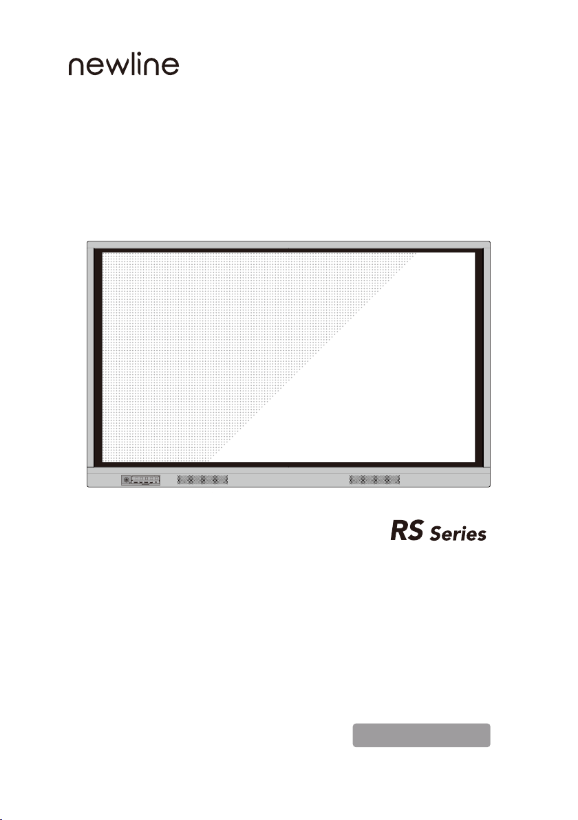
Home Return Menu Vol- Vol+
USB 2.0 USB 2.0 USB Touch HDMI IN MIC
Quick Start Manual
Version 2.0
Page 2
Welcome to the world of newline.
Thank you for choosing the newline RS series Interactive Touch Screen.
Please use this document to get the most out of your screen.
This device complies with part 15 of the FCC Rules. Operation is subject to the following two
conditions: (1) This device may not cause harmful interference, and (2) this device must accept
any interference received, including interference that may cause undesired operation.
NOTE 1: This equipment has been tested and found to comply with the limits for a Class B
digital device, pursuant to part 15 of the FCC Rules. These limits are designed to provide
reasonable protection against harmful interference in a residential installation. This equipment
generates, uses and can radiate radio frequency energy and, if not installed and used in
accordance with the instructions, may cause harmful interference to radio communications.
However, there is no guarantee that interference will not occur in a particular installation. If
this equipment does cause harmful interference to radio or television reception, which can be
interference by one or more of the following measures:
●
Reorient or relocate the receiving antenna.
●
Increase the separation between the equipment and receiver.
●
connected.
●
Consult the dealer or an experienced radio/TV technician for help.
NOTE 2: Any changes or modifications to this unit not expressly approved by the party
responsible for compliance could void the user’s authority to operate the equipment.
The symbol of the crossed out wheeled bin indicates this product
should not be placed in municipal waste. Instead, dispose of waste
equipment by handing it over to a designated collection point for the
recycling of electrical and electronic equipment.
Page 3
Symbol Conventions
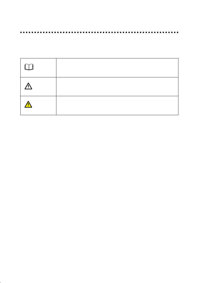
Symbols are used in this document to indicate operations that need particular attention. The
symbols are dened as follows:
NOTE
CAUTION
WARNING
Provides additional information to supplement operation in the main
text.
Indicates a potentially hazardous situation that, if not avoided, could
result in equipment damage, data loss, performance deterioration, or
unanticipated results.
Indicates a hazard with risk that, if not avoided, could result in death or
injury.
1
Page 4
Safety Instruction
For your safety, please read the following instruction before you use the product. Serious injury
or property damage may be caused by improper operations. Do not try to repair the product on
your own.
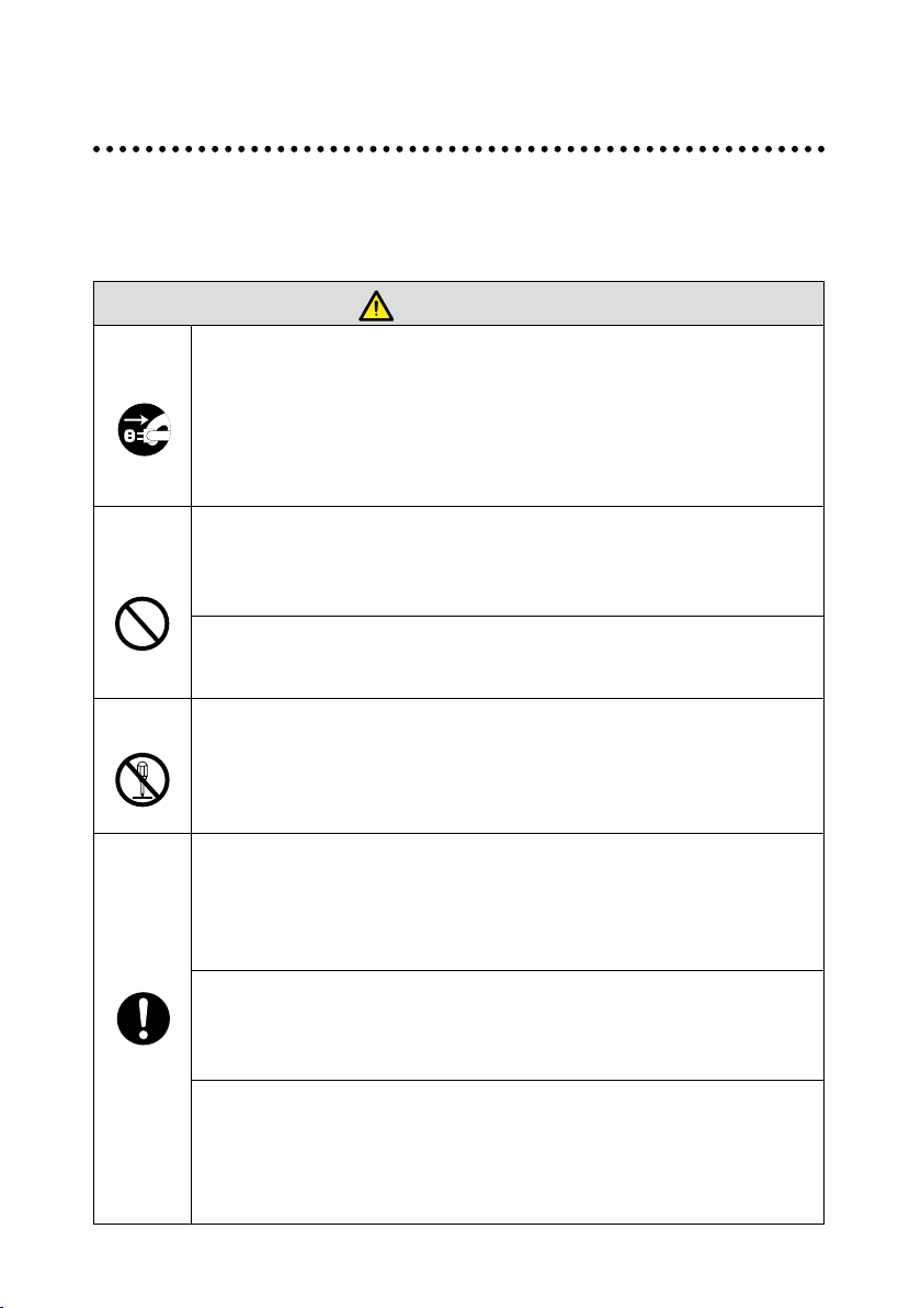
WARNING
Disconnect the product from power supply immediately if major failures
occur.
Major failures include the following:
●
Smoke, peculiar smell or abnormal sound is discharged from the product.
●
No image or sound is displayed, or the image error occurs.
In the preceding scenarios, do not continue to use the product. Disconnect
power supply immediately and contact professional sta for troubleshooting.
Do not drop liquid, metal or anything combustible into the product.
●
If any liquid or metal is dropped into the product, power o the product and
disconnect power supply, then contact professional sta for solutions.
●
Pay attention to children when they are close to the product.
Put the product on a stable surface.
An unstable surface includes and does not limited to an inclined plane, a
stand, desk or platform, which might cause turnover and damage.
Do not open the cover or change the product on your own.
High voltage components are installed in the product. When you open the cover,
high voltage, electric shock, or other dangerous situations may occur.
If inspection, adjustment, or maintenance is required, contact the local distributor
for help.
Use the specied power supply.
●
To prevent the product from being damaged, do not use any types of power cables
other than the one provided with the product.
●
Use a three-wire socket and ensure that it is properly grounded.
●
Pull out the power plug from the socket if the product is not used for a long period.
Clean the dust and metal on the power plug regularly.
●
Fire or electric shock may be caused if the product is powered on, when you
are cleaning.
●
Pull out the power plug before cleaning it with a dried cloth.
shaky
Power output port is 5V/2A.
The voltage/current of the rear power output port is 5V/2A (maximum). Purchase
the power code/AC adapter according to customer needs. The port can be used
for Newline Android box X10D. Please do not connect any products with dierent
power requirement. Otherwise, it may cause damage to products or re.
2
Page 5
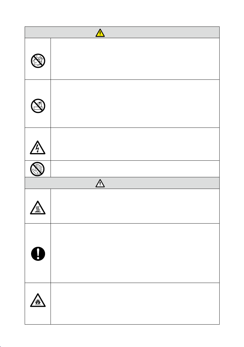
WARNING
Do not put items on the top of the product.
●
Do not put items, such as a container for liquid (a vase, owerpot, cosmetics
or liquid medicine) on the top of the product.
●
If any water or liquid is spilled on the product, a short circuit may occur and
cause re or electric shock.
●
Do not walk on or hang any items on the product.
Do not install the product in an improper place.
●
Do not install the product in humid places, such as the bathroom, the shower
room, near windows, or outdoor environments that experience rain, snow or
other harsh weather. Avoid installation near hot spring vapor. The preceding
environments may cause faults in the product or electric shock under extreme
conditions.
●
Do not put exposed re source, such as an ignited candle, on the product.
Pull out the power plug during thunderstorms.
●
Do not touch the product during a lighting storm to avoid electric shock.
●
Install or place components that supply high enough voltage to cause personal
injury out of the reach of children.
Do not touch the power cable with wet hands.
CAUTION
Do not install the product in high temperature environments.
●
Do not install the product near a heat source, such as a radiator, a heat
reservoir, a stove or other heating products.
●
Do not expose the product to direct sunlight, which may cause high
temperatures and subsequent faults in the product.
For transport.
●
Pack the product for transport or maintenance by using the cartons and
cushioning material provided with the product.
●
Vertically move the product during transport. The screen or other components
are easily broken if the product is moved by an improper way.
●
Before you move the product, disconnect all external connections and separate
all toppling preventing products. Move the product carefully to prevent it from
being hit or squeezed, especially the screen, which may cause injury if broken.
Do not cover or block up any vents on the product.
●
Any overheated components may cause re, damage the product, and shorten
the service life.
●
Do not lay the product down where the venting surface will be covered.
●
Do not install the product on a carpet or cloth.
●
Do not use a cloth such as table cloth to cover the product.
3
Page 6
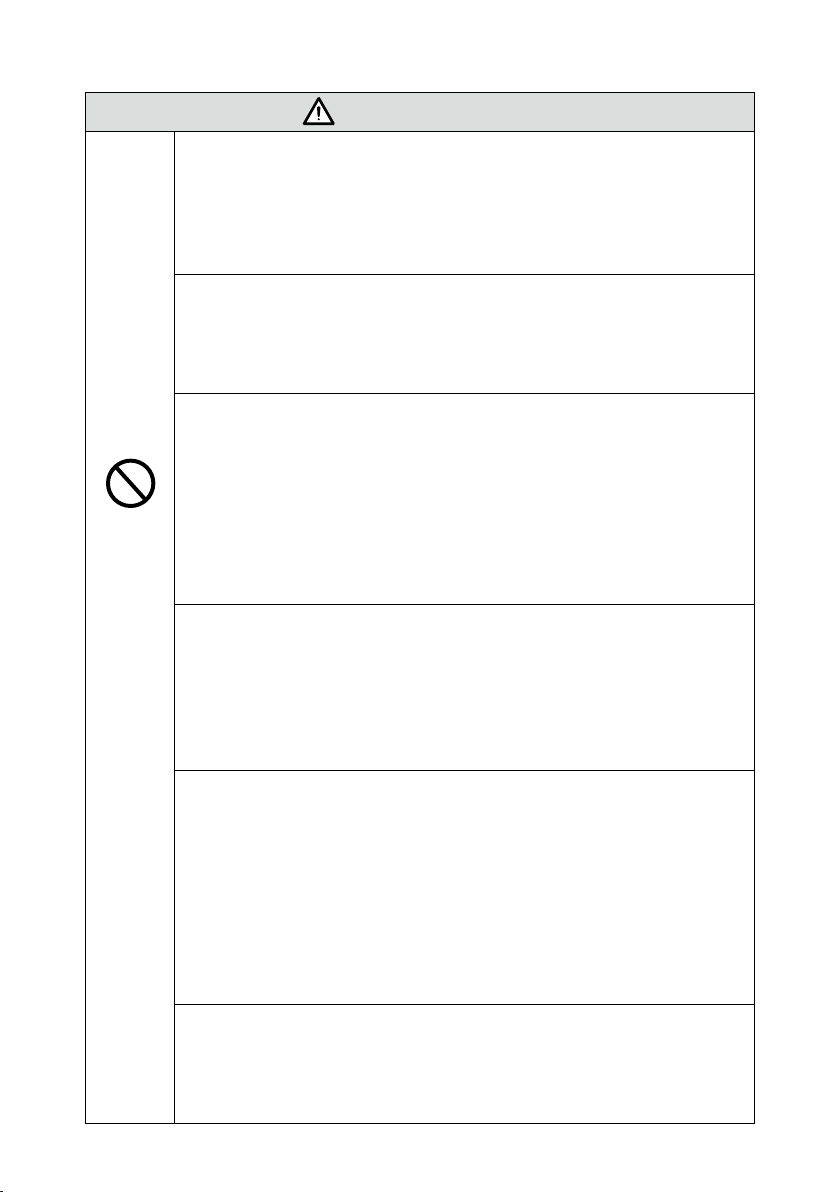
CAUTION
Keep away from the product when you use a radio.
The product complies with the international EMI standard to pervent radio
interference. However, interference may still exists and causes noise in the radio.
If noise occurs in the radio, try the following solutions.
●
Adjust the direction of the radio antenna to avoid the interference from the product.
●
Keep the radio away from the product.
Screen glass is broken or falls o.
●
In case of screen glass breakage, keep all personnel 3 meters away from the
screen to ensure safety.
●
Do not perform any installation or disassembly when the screen glass is
broken or falls o.
Use the battery correctly.
●
Galvanic corrosion, electric leakage, and even re may be caused by improper
battery usage.
●
It is recommended to use the designated type of battery and install the battery by
correct electrodes (positive and negative).
●
Do not install and use new battery with a used one.
●
Take out the battery if the remote control is not used for a long period.
●
Do not expose the battery to overheated environments such as sunlight and ring.
●
Dispose of the used battery based on your local regulations.
Do not damage the power cable.
●
Do not damage, change, twist, bend, or forcibly drag the power cable.
●
Do not put weights (such as the product itself) on the power cable.
●
Do not forcibly drag the cable when you pull out the power plug. If the power
cable is damaged, please contact the local distributor to repair or replace it.
●
The power cable in the accessory box is for this product only. Do not use it on
other products.
Additional advice:
●
U
se the product in an environment with comfortable lighting. It is harmful to your
eyes
to watch in a too bright or too dark environment.
●
Relax your eyes after a period of time for watching.
●
Keep sucient distance from the product to protect your eyes and prevent
eyestrain.
●
Adjust the volume to an appropriate level, especially at night.
●
Use amplier equipment as the audio input source with caution. If you must use amplier
equipment,
Otherwise, the speaker can become overpowered and damaged.
About USB port.
Front USB ports and rear USB 3.0/USB 2.0 ports switch connections based on
signal sources. If the current signal source is reading the data from an external
product connecting to the port, please switch the signal source after the data
reading is complete. Otherwise, the data or product may be damaged.
the input power should not exceed the maximum of speaker power.
4
Page 7
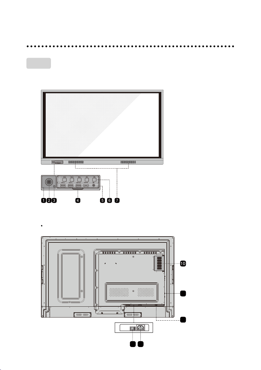
Parts
◆
Front View
◆
Rear View
TT-6518RS
Home Return Menu Vol- Vol+
USB 2.0 USB 2.0 USB Touch HDMI IN MIC
Parts and Functions
9 8
5
11
11
Page 8
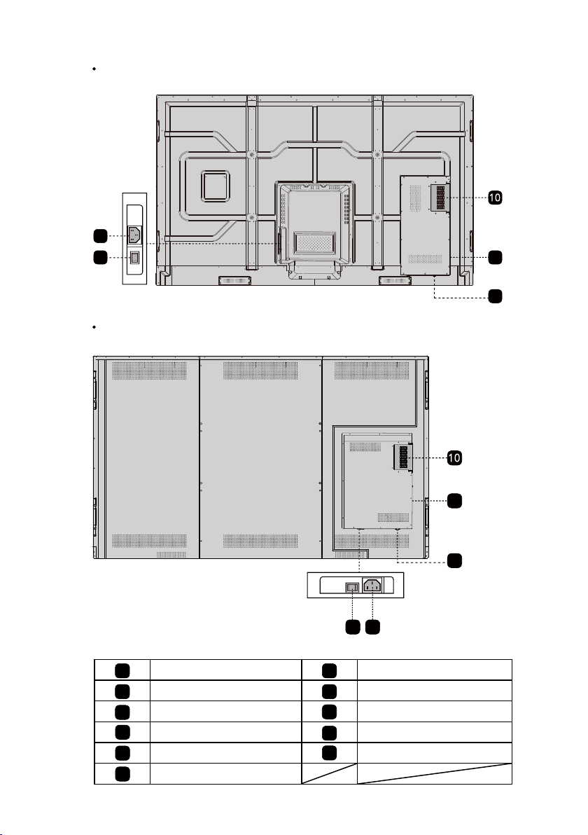
TT-7518RS/TT-8618RS
8
9
TT-9818RS
11
11
9 8
Remote control receiver
1
Power On/O
2
Light sensor Power Switch
3
Front Plate Cover
4
Front Ports
5
Front Buttons
6
7
8
9
10
11
6
11
11
Speakers
Power Supply Plug
Internal PC Port (OPS)
Rear Ports
Page 9
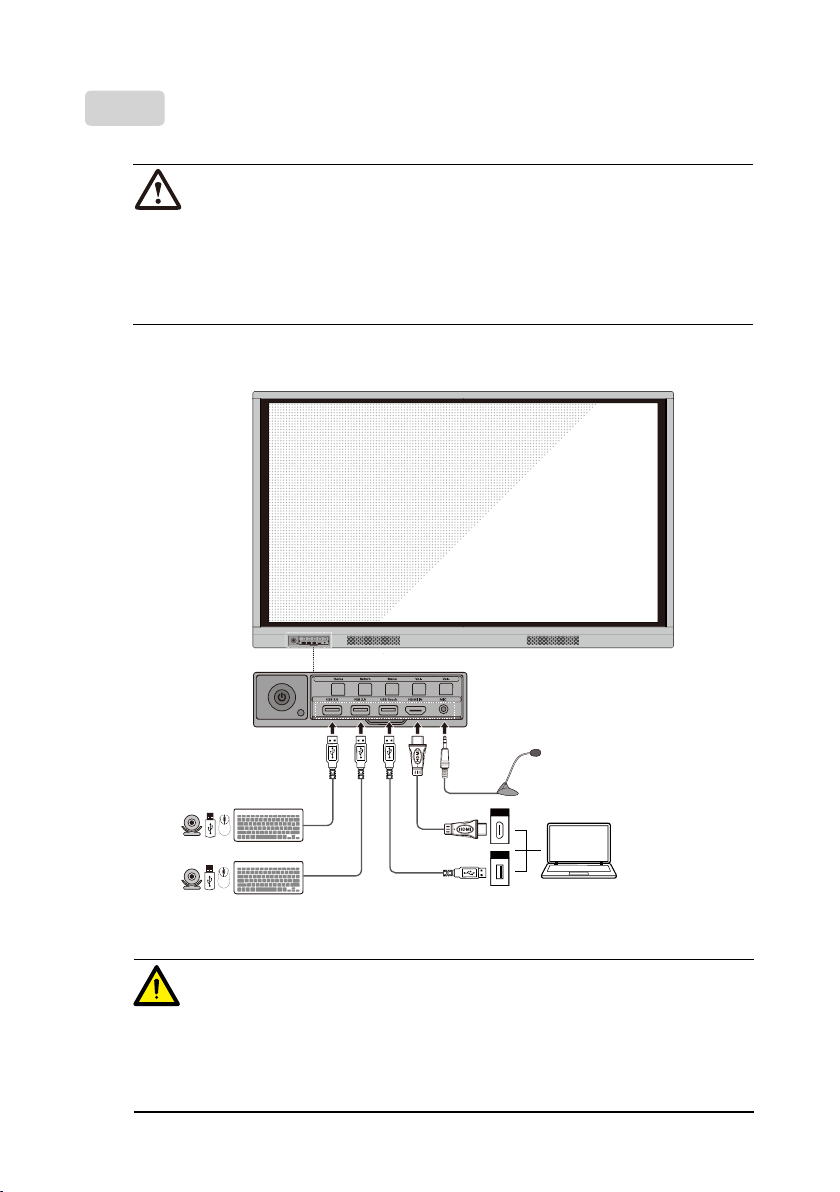
Ports
CAUTION
Front USB ports and rear USB 3.0/USB 2.0 ports switch connections based on signal sources.
If the current signal source is reading the data from an external product connecting to the port,
please switch the signal source after the data reading is complete. Otherwise, the data or
product may be damaged.
◆
Front Ports
Home Return Menu Vol- Vol+
USB 2.0 USB 2.0 USB Touch HDMI IN MIC
HDMI
USB
◆
Rear Ports
WARNING
The voltage/current of the rear power output port is 5V/2A (maximum). Purchase the power
code/AC adapter according to customer needs. The port can be used for Newline Android box
X10D. Please do not connect any products with dierent power requirement. Otherwise it may
cause the damage to products or re.
7
Page 10
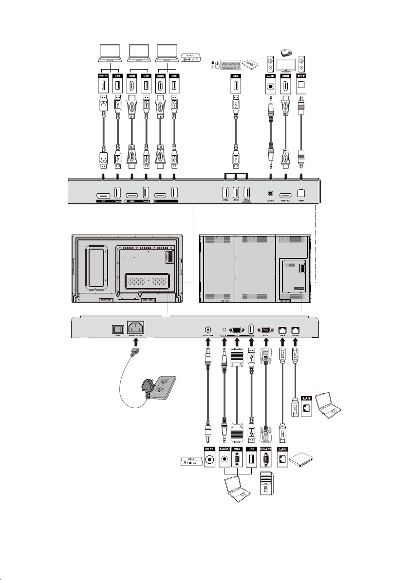
Touch
HDMI
TT-6518RS: TT-9818RS
8
Page 11
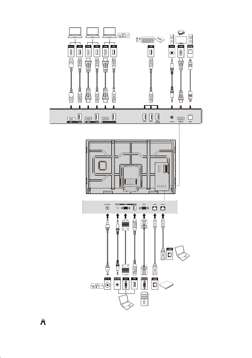
Touch
HDMI
TT-7518RS/TT-8618RS:
Tip:
You are advised to connect X10D to HDMI rear 2.
9
Page 12
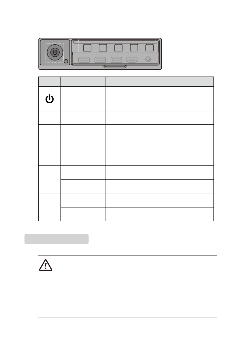
◆
Front Buttons
Home Return Menu Vol- Vol+
USB 2.0 USB 2.0 USB Touch HDMI IN MIC
Buttons Operations Functions
Power on/o
●
Short press
Steady on red: shut down modes
●
Steady on blue: working state
Home
Return
Short press Go to the home page
Short press Return to the last menu/Exit
Short press Open the setting menu
Menu
Long press for more
than 2 seconds
Screen Lock
Short press Decrease the sound volume
Vol-
Long press for more
than 1 second
Decrease the sound volume continuously
Short press Increase the sound volume
Vol+
Long press for more
than 1 second
Increase the sound volume continuously
Remote Control
CAUTION
Carefully read the following instructions before using the remote control to avoid possible faults:
●
Do not drop or damage the remote control.
●
Do not spill water or other liquids on the remote control.
●
Do not place the remote control on a wet object.
●
Do not place the remote control directly under sunlight or near an overheating heat source.
10
Page 13
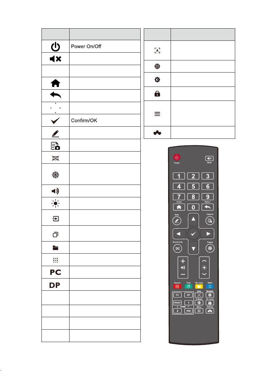
Buttons Functions
Mute/Unmute Audio
1-9
Enter number
Go to the Home Page
Return to Previous/Exit
Up/Down/Left/Right
Enter Whiteboard Mode
Take a Screenshot
Enable Sound Only Mode
Freeze the Current Screen,
Click Again to Exit Freeze
Function
Adjust the Sound Volume
Adjust the Brightness
Enter the Source Selection
Page
View Currently Running
Applications
Buttons Functions
Autocorrection Screen
Display (For VGA Signal
Source)
Open the Browser Application
Toggle Display Backlight
Mode
Start/Exit the Screen Lock
Function
● Open the Signal Source
Menu (Short Press)
● Screen Lock (Long Press
for More than 2 Seconds)
Open the System Settings
Open the File Manager
View all Pre-installed
Applications
Switch Source to Internal PC
Switch Source to Display Port
HDMI
FRONT
HDMI 1 Switch Source to HDMI 1
HDMI 2 Switch Source to HDMI 2
VGA Switch Source to VGA
Switch Source to HDMI Front
11
Page 14
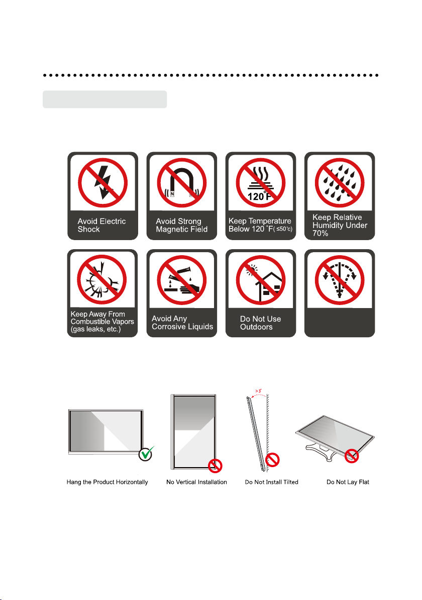
Safety Precautions
◆
Installation Environment
Installation Guide
Do Not Install
Tilted
◆
Installation Direction
12
Page 15
Installation Precautions
◆
Weight Loading
Weight of the product: 293 lb/ 133 kg (TT-9818RS), 161 lb/ 73 kg (TT-8618RS),123 lb/
56 kg(TT-7518RS), 99 lb/ 45 kg (TT-6518RS)
●
When using a mobile stand, ensure that the weight of the product is less than the
loading capacity of the mobile stand.
●
When using the wall-mount bracket, ensure that the wall can support the weight of
the product. We recommend that the wall surface be reinforced and have a loading
capacity 4 times of the weight of the product. Consult a professional installer for
wall-mount installation.
Note
The company does not undertake relevant legal responsibility for any problems caused by
improper operation, if the third party mobile stand, or wall-mount bracket is beyond the
scope of the product.
●
Do not install the product where it might be hit by a door.
◆
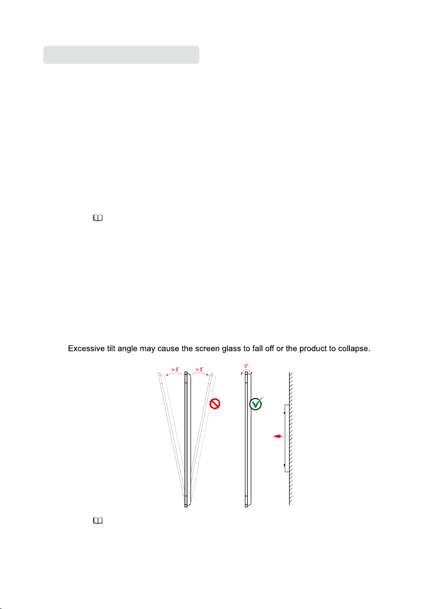
Vertical installation
When installing, try to keep the product vertical. The vertical tilt range allowing for
wall-mount installation is ±3 degrees.
Note
For any problem, please contact our support desk.Our company is not responsible for any
damage or losses incurred by users if the users fails to follow the instructions.
13
Page 16
◆
in)
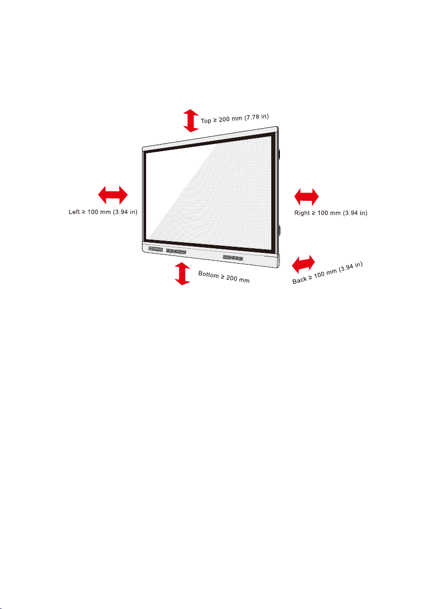
Ventilation
Ensure adequate ventilation and/or air conditioning environment. We recommend
keeping certain distances from the side of the product to the wall or panels. Ventilation
requirements are shown in following gure.
Home
R
etu
r
n
Me
n
u
VOL-
V
OL+
USB 2.0
USB
2.0
U
SB
T
ou
ch
HDMI
MIC
(7. 78
14
Page 17
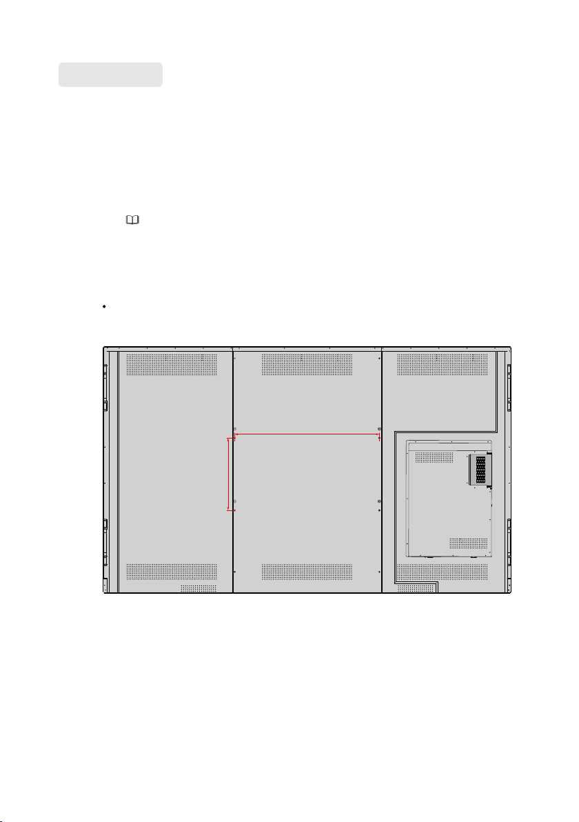
Installation
The dimensions of the four bracket mounting holes on the back panel are VESA
MIS-Fcompliant (TT-9818RS, TT-8618RS or TT-7518RS: 800 x 400 mm/31.50 x
15.75 in; TT-6518RS: 600 x 400 mm/23.62 x 15.75 in). Use metric M8 screws with
length of 10 mm to 15 mm (0.40 to 0.59 in) to secure the touch screen with the
mounting system. Dimensions of themounting holes on the back panel are shown
on the following gure.
Note
Consult a professional installer to install the display product.
TT-9818RS:
M8
400mm(15.75 in)
M8 M8
800mm(31.50 in)
15
M8
Page 18
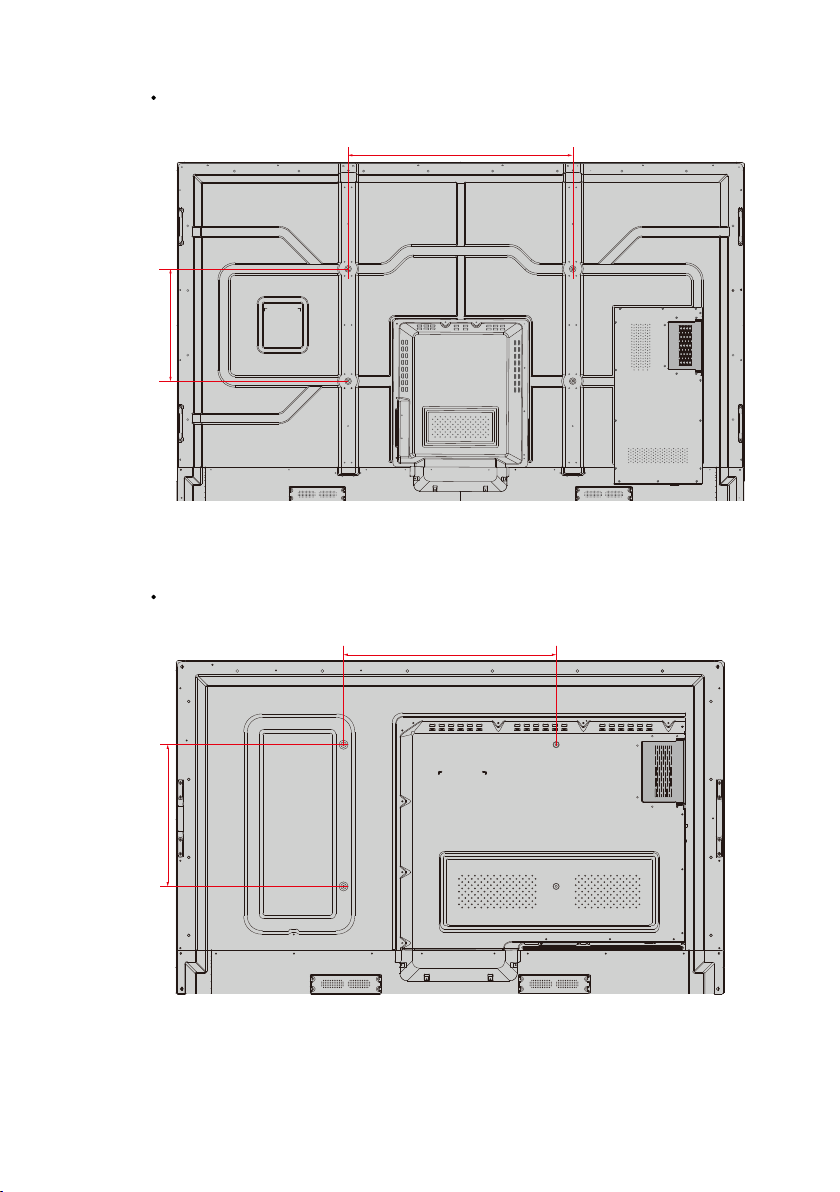
TT-7518RS/TT-8618RS:
800mm(31.50 in)
400mm(15.75 in)
TT-6518RS:
400mm(15.75 in)
M8
M8
M8
M8
M8
600mm(23.62 in)
M8
M8
M8
16
Page 19
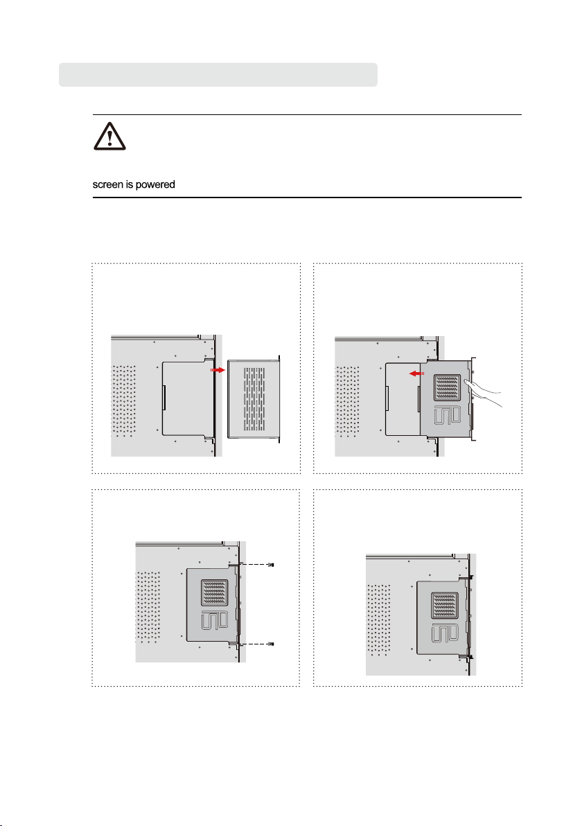
Installing the Internal PC (Optional)
CAUTION
The internal PC does not support hot plugging. Therefore, you must insert or remove it when the
off .Otherwise,the screen or internal PC may be damaged.
You will need to purchase the internal PC separately. Perform the following steps to install the
internal PC.
ay be damaged.
Step 1: Unscrew the M3 screws by
hand to remove the internal PC
shielding cover.
Step 3: Secure the internal PC to the
display by using the M3 screws.
M3
M3
Step 2: Push the internal into the
internal PC port at the rear of
the screen from right to left.
Step 4:
Ensure the installation is
correct before turning the
power on again.
17
Page 20
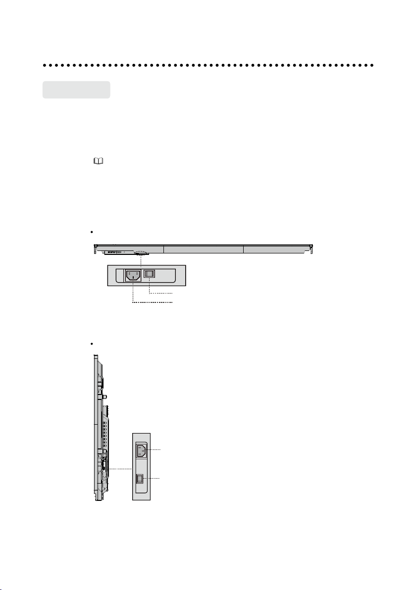
Turning On/Off
Power On
Step 1: Plug the power supply into the power outlet fully and plug the power connector
into the side of the product. Ensure the power is in the range of 100V to 240V
with frequency at 50 Hz/60 Hz ± 5%. The power current must be grounded.
Note
The power outlet should be installed near the equipment and shall be easily accessible.
Step 2: Flip on the power switch located on the side of the product to “On”.
TT-9818RS:
Power Switch
Power Supply Plug
TT-7518RS/TT-8618RS:
Power Supply Plug
Power Switch
18
Page 21
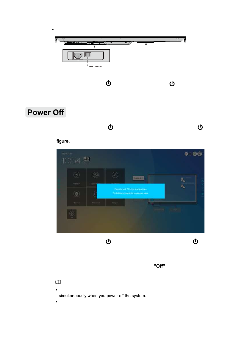
TT-6518RS
Power Switch
Power Supply Plug
Step 3:
Press the power button
on the front control panel or on the remote control.
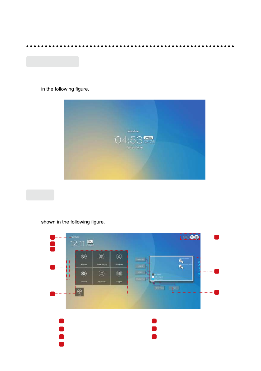
Step 1: Press the power button on the front panel or the power button on the
remote control. The information will be displayed as shown in the following
Step 2: Press the power button on the front panel or the power button on the
remote control again. the power indicator will turn to red.
Step 3: If you are not going to use the product for an extended period of time, we
recommend you to switch the power switch to
.
Note
If an internal PC is equipped, the interna l PC and th e screen are powered off
Do not forcibly disconnect the power supply of the screen when the internal PC is on.
19
Page 22
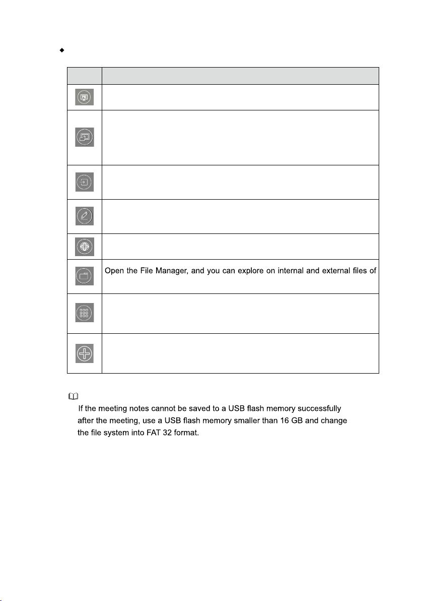
Operating the Touch Screen
Start Screen
When the product is turned on, the product will show the start screen page. As shown
Home
Touch the screen to start a meeting, and the product will go to the Home page. As
1
2
3
4
6
1
Logo (Shortcut to Settings)
2
Clock (Shortcut to Clock)
3
Date and Week
4
Side Toolbar
5
4
7
5
Status Bar and Settings
6
Main Icon
7
Preview Window for Signal Source
20
Page 23
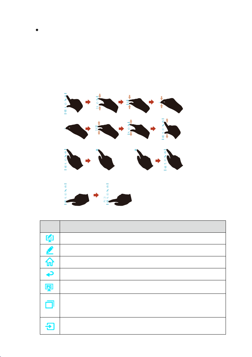
Main Icon
Icon Functions
Switch to the internal PC source.
Click “Screen sharing” to enable the wireless screen sharing function.
Note: By default, the “Screen sharing” icon is displayed after startup.
When you click “Add” or “Gadget” icon, “Screen sharing” switches to the
“Connection” icon.
Click Connection to view the connected sources, including Built-in PC,
HDMI 1, HDMI 2, DisplayPort, HDMI Front and VGA.
Discussion provides discussion board funct ion and screen annotation
functions.
Click to enter browser.
the screen.
Gadget displays all pre-installed applications, including Gallery, Browser,
Music, Calculator, E-mail, File viewer, Keyboard, Office viewer and
Trucast express. Click the icon of an application to run the application.
Click Add to enter Add page, you can add up to 5 shortcuts to your favorite
software, gadgets or connections to the Home page. (See more detail in “Add
Shortcuts to Home Page”)
Note
21
Page 24
Side Toolbar
The Annotation Mode/Discussion Mode/Home/Return/Windows icons are displayed
by default in the toolbar at two sides of the screen. The bottom side tool bar can be
customized as your choice (The default icon is Windows). Long press the icon at the
bottom of shortcut keys at both sides to start other functions expanded quickly. You may
also hide the side tool bar at the setting or move it up and down, shrink or expand by
gestures. You may double-click the “=” to expand or shrink the toolbar. Long press the
customized icon to unfold level-2 icons.
Shrink1:
Expand1:
Expand2:
Shrink2:
Unfold level-2 icons :
long press
The functions of the side toolbar are as follows:
Icon Functions
Enter annotation mode, and click again to stop annotation and take a screenshot.
Enter discussion mode.
Go to Home page.
Return to the last menu/Exit
Enter the internal PC source.
Manage currently running applications.
Slide up/down the currently running application or click “×” at the upper right
corner to close the application.
Enter the favorite source. You can set favorite source in the “tool bar”
submenu in the system settings.
double clickdouble click
22
Page 25
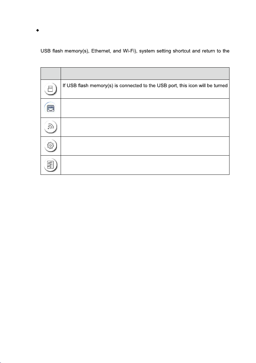
Status Bar and Settings
The upper right corner of the home page displays three working status icons (including
start screen page.
Icon Functions
on.
If the product is connected to Ethernet, the icon will be turned on.
If the product is connected to a wireless network, the icon will be turned on.
Access the system setting page.
Return to the start screen page.
23
Page 26
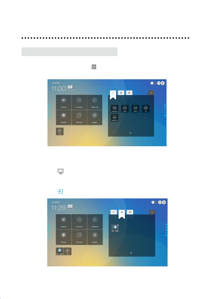
Add Shortcuts to Home Page
Step 1:
On Home page, click the
shortcuts will be displayed.
Step 2:
Click the icons on top to switch the list between external signal sources, Windows
programs and pre-installed gadgets.
●
Click to view the Windows programs that the Newline Assistant uploads to
the
Smart system. For details,see "Add Quick Start Windows Programs in
Smart System".
●
Click to view signal sources in Connection.
icon in the lower right corner. The interface for adding
Add Shortcut
24
Page 27
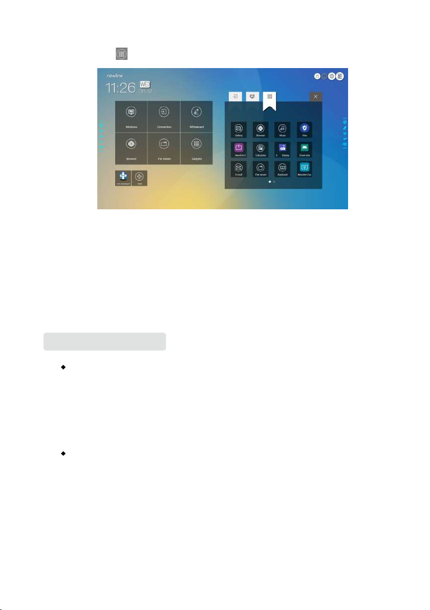
●
Click
Step 3:
Add or delete applications on the tab.
●
In the list, click the icon to add it to the shortcut on the home page. The check icon
to view Gadget applications.
will appear at the upper right corner of the shortcut icons. Up to 5 shortcuts can be
added.
●
Tap the icon with the check mark again, the check icon will disappear and the shortcut
will be deleted from the Home page.
Step 4:
At the Home page, click the shortcut icon and you can start the program/
application or change to the external signal source.
Newline Assistant
Introduction
Newline Assistant is the tool used as a bridge between smart system and Internal PC
(OPS). It helps to add windows software to smart system as well as to protect USB data
when switching between sources.
Therefore we strongly recommend users install Newline Assistant after installing the
internal PC.
Installation
Step 1: Connect Internal PC correctly (See also "Installing the Internal PC (Optional) ").
Step 2: On the Home page, click Windows. It will switch the signal source to Internal
Windows system.
Step 3: Log in to the website www.newline-interactive.com and choose Products >
Software to download the Newline Assistant installation package.
Step 4: Install Newline Assistant as instructed.
25
Page 28
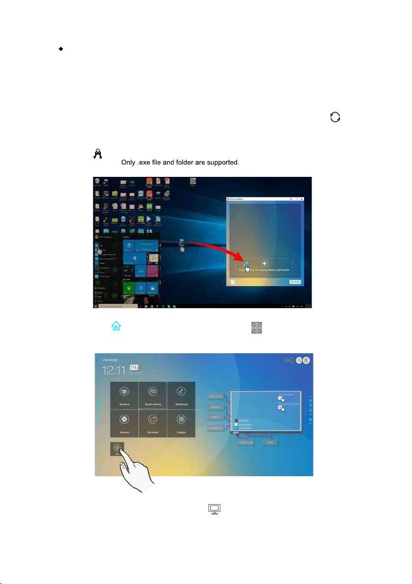
Add Quick Start Windows Programs in Smart System
Step 1: In Windows, run the Newline Assistant program and drag the software icons or
folder shortcut icons that you want to add from desktop or menu to the Newline
Assistant window. The applications added or deleted through the Windows
system will be automatically updated to the smart system until the upload
progress reaches 100%. If there is an application not updated, click
upper right corner to manually update all icons in the Newline assistant window
to the smart system.
Tip:
Step 2:
Click to return to the Home page. Click the icon and go to shortcut setting.
The
page for adding application program will be displayed.
in the
Step 3:
At the shortcut setting page, click icon to view all the Windows programs
added by Newline Assistant in Step 1.
26
Page 29
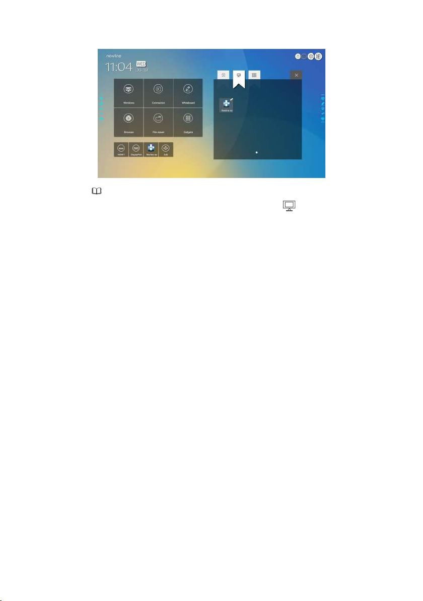
Note
By default, the Newline Assistant application is added on the
Step 4:
Tap the icon and add the shortcut at the Home page. Tap again and remove it.
Step 5:
Return to Home page. Click the icon of an added Windows application to start
the software.
tab.
27
Page 30
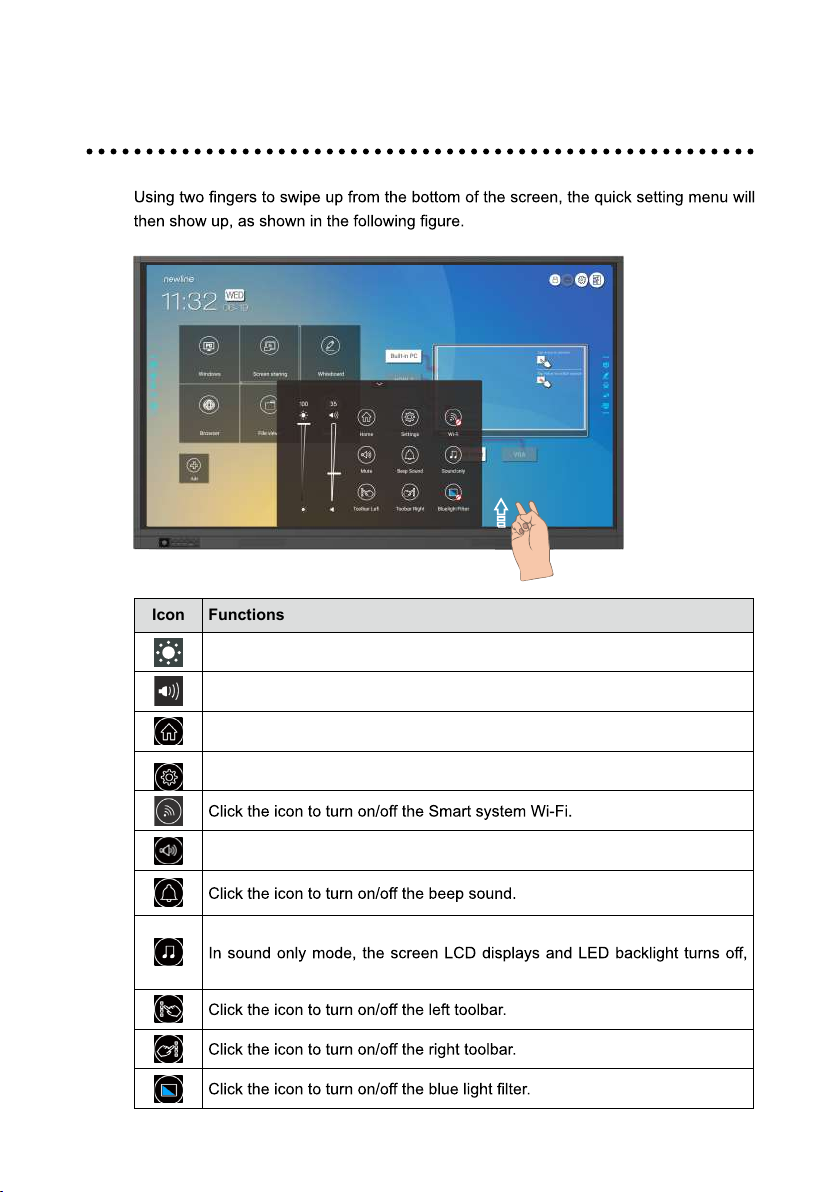
Icon Functions
Drag the slider to adjust the brightness.
Drag the slider to adjust the volume.
Quick Setting Menu
Click the icon to return to Home page.
Click the icon to enter the settings page.
Click the icon to mute/unmute.
Click the icon to enable sound only mode.
other functions are in normal operating condition.
28
Page 31

More Information
For more information
Please visit our website (www.newline-interactive.com) for detailed instruction manual.
Contact Us for Support
Please email us at [email protected].
Our company is devoted to product innovation and technology enhancement. Therefore, we may change product specs and
information without notice, Product pictures in the manual are for reference only, please refer to actual products.
29
Page 32

20302-T8I5-004010
 Loading...