

Page 1

W130/W130TC
Copyright © New Holland
WHEEL LOADER
Workshop Manual
Print N° 604.13.492.00 English
II - 2005
THIS ALERT SYMBOL SIGNALS IMPORTANT MESSAGES INVOLVING YOUR SAFETY.
Read and heed carefully the safety instructions listed and follow the precautions recommended to
avoid potential risks and to safeguard your health and your safety.
You will find this symbol in the text of this Manual referred to the following key words:
WARNING
Cautions directed to avoid improper repair interventions involving potential consequences for the
operator’s safety.
DANGER
These warnings qualify specifically potential dangers for the safety of the operator or other persons directly or indirectly involved.
IMPORTANT NOTICE
All maintenance and repair interventions explained in this Manual must be performed exclusively by the Service
Organization of the Manufacturer, observing strictly the instructions explained using, whenever necessary, the
recommended specific tools.
Whoever performs the operations reported without following exactly the precautions is responsible on his own, for
the damages that may result.
Neither the Factory nor any Organizations in its Distribution Network, including but not limited to national, regional
or local distributors, are responsible for any liability arising from any damage resulting from defects caused by parts
and/or components not approved by the Factory for use in maintaining and/or repairing products manufactured or
merchandized by the Factory.
In any case, no warranty of any kind is made or shall be imposed with respect to products manufactured or merchandized by the Factory, when failures are caused by the use of parts and/or components not approved by the
Factory.
Page 2

AVOID ACCIDENTS
Copyright © New Holland
Most accidents and injuries occurring in industry, on
the farm, at home or on the road, are caused by the
failure of some individual to follow simple and fundamental safety rules or precautions. For this reason,
MOST ACCIDENTS CAN BE PREVENTED by recognizing the real cause and taking the necessary precautions, before the accident occurs.
Regardless of the care used in design and construction of any type of equipment, there may be conditions
that cannot be completely safeguarded against without interfering with reasonable accessibility and efficient operation.
A careful operator is the best insurance against accidents. The complete observance of one simple rule
would prevent many thousands serious injuries each
year.
This rule is: Never attempt to clean, lubricate or adjust
a machine while it is in motion.
WARNING
On machines having hydraulically, mechanically and/or cable
controlled equipment (such as showels, loaders, dozers,
scrapers etc.) be certain the equipment is lowered to the
ground before servicing, adjusting and/or repairing.
If it is necessary to have the equipment partially or fully raised
to gain access to certain items, be sure the equipment is suitably supported by means other than the hydraulic lift cylinders, cable and/or mechanical device used for controlling the
equipment.
Page 3

SUMMARY
Copyright © New Holland
GENERALITIES.................................................... Section 0
ENGINE ................................................................ Section 1
TRANSMISSION................................................... Section 2
BRAKE SYSTEM.................................................. Section 3
STEERING SYSTEM ............................................ Section 4
BUCKET BOOMS AND FRAME .......................... Section 5
EQUIPMENT HYDRAULIC SYSTEM ................... Section 6
ELECTRICAL SYSTEM........................................ Section 7
CAB ...................................................................... Section 8
Page 4

Copyright © New Holland
Page 5

SECTION 0
Copyright © New Holland
GENERALITIES
INDEX
SUBJECT PAGE
SAFETY RULES ........................................................................................................................................... 0-1
SPECIFICATIONS........................................................................................................................................ 0-8
DIMENSIONS AND WEIGHT .......................................................................................................................0-19
TABLE OF FLUID CAPACITIES ...................................................................................................................0-20
UNITS OF MEASURE .................................................................................................................................0-21
STANDARD TORQUE SPECIFICATION .......................................................................................................0-23
LOCTITE PRODUCT CHART.......................................................................................................................0-27
Page 6

Copyright © New Holland
Page 7

GENERALITIES
Copyright © New Holland
SAFETY RULES
0 - 1W130/W130TC
GENERALITIES
Read this Manual carefully before starting, operating,
maintaining, fuelling or servicing the machine.
Read and comply with all safety precautions before any
intervention.
Do not allow unauthorised personnel to operate or service this machine.
Do not wear rings, wrist watches, jewellery, loose or hanging garments, such as ties, torn clothing, scarves, unbuttoned or unzipped jackets that can get caught in moving
parts. Wear certified safety clothes such as: hard hat, noslip footwear, heavy gloves, ear protection, safety glasses,
reflector vests, respirators. Ask your employer about specific safety equipment requirements.
Keep the operator’s compartment, step plates, grab-rails
and handles clean and clear of foreign objects, oil, grease,
mud or snow to minimize the danger of slipping or stumbling. Remove mud or grease from your shoes before
attempting to mount or operate the machine.
Do not jump on or off the machine. Always keep both hands
and one foot, or both feet and one hand in contact with
steps and grab rails.
Do not use controls or hoses as hand holds when climbing
on or off the machine. Hoses and controls are movable
parts and do not provide solid support. Besides, controls
may be inadvertently moved and cause unexpected
movement of the machine or its attachments.
Never operate the machine or its attachments from any
position other than sitting in the driver’s seat.
Keep head, body, limbs, hands and feet inside the operator’s compartment at all times to reduce exposure to
external hazards .
Be careful of possible slippery conditions of the steps and
hand rails as well as of the ground around the machine.
Do not leave the machine until it is has come to a complete
stop.
Check the seat safety belt at least twice per year and
replace it if it shows signs of wear, fraying or other
weakness that could lead to failure.
STARTING
NEVER START OR OPERATE A FAILED MACHINE. Before operating the machine, always ensure that any unsafe
condition has been satisfactorily corrected.
Check brakes, steering and attachment controls before
moving off. Report any malfuctioning part or system to the
maintenance managers for proper action.
Ensure all protective guards and panels as well as all
safety devices provided are in place and in good operating
condition.
Ensure that nobody is in the machine operating range
before moving off or operating the attachment. WALK
COMPLETELY AROUND the machine before mounting.
Sound the horn.
Before starting machine, check, adjust and lock the driver's
seat for maximum comfort and control of the machine.
Fasten your seat belts(when fitted).
Obey all flag signals and signs.
Due to the presence of flammable fluids on the machine,
never check or fill fuel tanks or accumulator batteries near
fires, open flames, or sparks.
REMEMBER THAT SPECIAL STARTING FLUIDS ARE
FLAMMABLE. Scrupolously follow recommendations
printed on the containers and in this Manual.
DO NOT PUNCTURE OR BURN CONTAINERS.
Containers must be stored in fresh, well ventilated places
and out of the reach of unauthorised persons. Strictly
follow the instructions provided by the Manufacturer.
Never use these products near fires, open flames, or
sparks.
OPERATING
Check wheel and rim retainers before each working shift.
If necessary, tighten to the torque specified.
Do not run the engine of this machine in closed buildings
without proper ventilation capable to remove harmful
exhaust gases.
Roll Over Protective Structures (ROPS) are required on
wheel or crawler loaders, dozers, or graders. NEVER
OPERATE the machine if such protective structure is
removed.
Keep the operator’s compartment free of foreign objects,
especially if not firmly secured. Never use the machine to
transport objects, unless proper securing points are provided.
DO NOT CARRY RIDERS ON THE MACHINE
Study and familiarize with escape routes alternate to
normal exit routes.
According to law provisions, seat belts must be fitted with
Roll Over Protection Structures or cabs. Keep safety belts
fastened during operation.
For your personal safety, do not climb on or off the machine
while it is in motion.
Make sure that bystanders are clear of the machine operating range before starting the engine and operating the
attachment. Sound the horn. Obey all indications provided
by flags, signs and signals.
DO NOT COAST OR FREEWHEEL down hills. Engage the
most suitable gear speed to keep the machine under control.
Carefully read personal and machine SAFETY PRECAUTIONS (at the beginning of this manual)
Page 8

0 - 2 W130/W130TC
Copyright © New Holland
GENERALITIES
SAFETY RULES
Do not operate the machine if you are extremely tired or feel
ill. Be especially careful towards the end of the working shift.
Do not operate a machine with misadjusted brakes.
Operate the machine at low speed which can ensure
complete control at all times.
Travel slowly over very rough terrain, slopes or near drop-
offs, in congested areas or on frozen or slippery surfaces.
When backing, always look to where the machine is to be
moved. Be alert of the position of bystanders. Should
someone enter the work area, STOP THE MACHINE.
Maintain a safe distance from other machines or obstacles
to ensure required visibility conditions. Give way to loaded
machines.
Maintain a clear vision of the surroundings of the travel or
work area at all times. Keep cab windows clean and
repaired.
When machines are operating in tandem, the pusher (rear)
must be equipped with the appropriate deflectors to protect
the front unit driver against the air stream coming from the
blower fan.
When pulling or towing through a cable or chain, do not
start suddenly at full throttle. Take-up slack carefully.
Carefuly inspect the towing items for flaws or problems
before proceedig.
Avoid kinking or twisting chains or cables. Do not pull
through a kinked chain or cable as the high stresses
existing in this condition may induce failures. Always wear
heavy gloves when handling chains or cables.
Chains and cables should be securely anchored. Anchor
points should be strong enough to withstand the expected
load. Keep anyone clear of anchor points and cables or
chains.
DO NOT PULL UNLESS THE OPERATOR’S COMPARTMENTS OF THE MACHINES INVOLVED ARE PROPERLY PROTECTED AGAINST POSSIBLE BACKLAS IN
CASE OF CABLE OR CHAIN FAILURE OR DETACHMENT.
Be alert of soft ground conditions close to newly constructed walls. The fill material and machine weight may
cause the wall to collapse.
In darkness, check area of operation carefully before
moving in with the machine. Use all lights provided. Do not
move into low visibility areas.
If the engine tends to stall for whatever reason under load
or at idle, immediately report this problem to the maintenance managers for proper action. Do not operate the
machine until this condition has been corrected.
On machines fitted with suction radiator fans, regularly
check the engine exhaust system for leaks, as exhaust
fumes expelled towards the operator are toxic.
Operators must know thoroughly the performances of the
machine they are driving.
When working on slopes or near sudden level drops in the
terrain, avoid areas where ground is loose or soft since
overturn or loss of machine control could result.
If noise level is high and continuosly exceeds 90 dBA over
8 hours at the operator's ear, wear approved ear protection
in compliance with local regulations.
Where counterweights are provided, do not operate the
machine if they have been removed.
When transporting a loaded bucket, keept it as rolled-back
and low as possible for maximum visibility, stability and
safety of there machine. Ground speed should be adequate to the load and ground conditions.
The load must always be properly arranged in the bucket;
move with extreme care when transporting oversize loads.
Use only the type of bucket recommended for the machine
and the materials to be handled. Follow the recommendations concerning loading capacity, arrangement of the
materials, characteristics of the ground and job to be
performed.
Do not lift and move loads overhead where persons are
standing or working, nor downhill when working crosswise
on slopes. In this case, the bucket should be unloaded on
the uphill side, whenever possible.
Start and stop the machine carefully when the bucket is full.
Do not move off without first reducing engine speed.
Overtaking manoeuvres should be performed only when
absolutely necessary and unavoidable. Beware possible
uneven terrains, poor visibility, presence of other machinery or persons out of sight.
Operate the machine at a speed adequate to the working
site conditions and in any case slow enough to ensure
complete control at all times.
Check instruments at start-up and frequently during
operation. Stop the machine immediately should any
malfunction be signalled.
Never use the bucket as a man lift or to carry riders.
Never use the machine as a work platform or scaffolding,
nor for other improper use (such as pushing railway cars,
trucks or other machines).
Pay attetion to people within the machine operating range.
Load trucks from the driver’s side whenever possible.
Prior to operating the machine, check which obstacles
and/or difficulties you will encounter, such as narrow
streets, overhead doors, cables, piping, as well as ground,
bridges, paving and ramps bearing load limitations.
In case of road transfers, find out beforehand what conditions are likely to be encountered, such as size restrictions,
heavy traffic, paving type, etc.. Beware fog, smoke or dust
that obscure visibility.
When crossing gullies or ditches, move at an angle with
reduced speed after ensuring ground conditions will permit a safe traverse.
Carefully read personal and machine SAFETY PRECAUTIONS (at the beginning of this manual)
Page 9

GENERALITIES
Copyright © New Holland
SAFETY RULES
0 - 3W130/W130TC
Always inspect the working area to identify potential risks
such as: inclines, overhangs, trees, demolition rubble,
fires, ravines, steep slopes, rough terrain, ditches, crowns,
ridge trenches, heavy traffic, crowded parking and service
areas, closed ambients. In such conditions, proceed with
extreme care.
Whenever possible, avoid going over obstacles such as
very rough terrain, rocks, logs, steps, ditches, railroad
tracks. When obstructions must be crossed, do so with
extreme care and at an angle, if possible. Slow down and
select a lower gear. Ease up to the break-over point, pass
the balance point slowly and ease down the other side.
In steep down-hill operation, do not allow the engine to
over-speed. Select the proper gear before starting down
grade.
Avoid crosswise hill travel, whenever possible. Drive up
and down the slope. Should the machine start slipping
sideways when going uphill, steer and turn machine front
immediately downhill.
The gradient you may attempt to overcome is limited by
factors such as ground conditions, load being handled,
machine type and speed, and visibility.
There is no substitute for good judgement and experience
when working on slopes.
Avoid operating the attachment too close to an overhang
or high wall, either above or below the machine. Beware
of caving edges, falling objects and landslips. Remember
that such hazards are likely to be concealed by bushes,
undergrowth and such.
When pushing-over trees, the machine must be equipped
with proper overhead guards. Never drive a machine up
the roots, particularly while the tree is being felled. Use
extreme care when pushing over any tree with dead
branches.
Avoid faggots, bushes, logs and rocks.
NEVER DRIVE OVER THEM, nor over any other surface
irregularities that discontinue adherence or traction with
the ground, especially near slopes or drop-offs.
Be alert to avoid changes in traction conditions that could
cause loss of control. AVOID driving on ice or frozen
ground when working on steep slopes or near drop-offs.
Working in virgin rough terrains is characterized by the
presence of all the perils and risks listed above. In these
conditions, it is emphasised the danger represented by
large tree limbs (possibly falling on the machine), large
roots (which may act as a leverage under the machine
when up-rooted and cause the unit to overturn), etc.
STOPPING
When the machine is to be stopped for whatever reason,
do so following the instructions given in chapters “Stop-
ping the machine” and “Shutting off the engine" in the
Operation and Maintenance Instruction Manual.
Always remember to move the gearshift lever to the neutral
position and engage the control lever lock for safety
purposes.
Apply the parking brake (if fitted).
NEVER LEAVE THE MACHINE UNATTENDED with the
engine running.
Prior to leaving the operator’s seat,and after making sure
that all people are clear of the machine, always slowly
lower the attachment until resting it safely to the ground
Park the machine in a non-operating and no-traffic area.
Park on firm level ground. If this is not possible, position the
machine at a right angle to the slope, making sure there is
no danger of uncontrolled sliding. Apply the parking brake.
If parking in traffic lanes cannot be avoided, provide
appropriate flags, barriers, flares and signals as required
to adequately warn the oncoming drivers.
Keep head, body, limbs, hands and feet clear of the dozer,
arms, bucket or ripper when raised.
Always switch off the battery isolator switch before servicing the machine in whatever manner (i.e., cleaning,
repairing, maintaining, etc.). Do the same when the
machine is to remain parked for prolonged periods of time
to avoid accidental or unauthorized starting.
Never lower the attachments other than sitting in the
operator’s seat. Sound the horn. Make sure that nobody is
within the machine operating range. Lower the attachment
slowly. DO NOT USE FLOAT POSITION in case of hydraulic controls.
Securely block the machine and lock it every time you
leave it unattended. Return keys to authorized security.
Perform all necessary operations as detailed in the Operation and Maintenance Instruction Manual. Apply the parking brake (if fitted) every time you leave the machine.
MAINTENANCE
GENERALITIES
Before operating or performing any intervention on the
machine:
- carefully read all the norms contained in this Manual;
- read and observe all safety plates and instructions
located on the machine.
Do not allow unauthorized personnel to service the machine. Do not carry out any maintenance work without prior
authorization. Follow all recommended maintenance and
service procedures.
Keep the operator’s compartment free of loose objects that
are not properly secured.
Do not wear rings, wrist watches, jewellery, loose or
hanging garments, such as ties, torn clothing,
scarves,unbuttoned or unzipped jackets that can get
caught in moving parts.
Carefully read personal and machine SAFETY PRECAUTIONS (at the beginning of this manual)
Page 10

0 - 4 W130/W130TC
Copyright © New Holland
GENERALITIES
SAFETY RULES
Wear certified safety clothes such as: hard hat, no-slip
footwear, heavy gloves, ear protection, safety glasses,
reflector vests, respirators. Ask your employer about specific safety equipment requirements.
Never service the machine with someone sitting in the
driver's seat, unless this person is an authorized operator
assisting in the maintenance being carried out.
Keep the operator’s compartment, step plates, grab rails
and handles clear of foreign objects, oil, grease, mud or
snow to minimize the danger of slipping or stumbling.
Clean mud or grease from your shoes before climbing on
the machine or driving it.
Never attempt to operate the machine or its attachments
from any position other than sitting in the operator’s seat.
Never stand under the boom.
Should it be necessary to move the attachment through the
hydraulic controls for maintenance purposes, remember
that this should be done while sitting in the operator’s seat.
Before starting the machine or moving its attachment,
apply the brakes, sound the horn and call that you are
about to manoeuvre. Raise the attachment slowly.
Always lock machine arms or any other parts that must be
lifted for maintenance purposes using adequate external
means. Do not allow anyone to pass near or even below
a raised yet unlocked attachment. If you are not absolutely
sure about your safety, do not stay under a raised attachment, even if it is locked.
Do not place body, limbs, or fingers near articulated cutting
edges of uncontrolled machine parts or deprived of the
necessary guards, unless they are suitably and safely
locked.
Never perform any work on the machine with the engine
running, except when this is specifically required. Do not
wear loose clothing, jewellery or such near moving parts.
When service or maintenance require access to areas that
cannot be reached from the ground, use a ladder or step
platform conforming to regulations in force. If such means
are not available, use machine grab rails and steps.
Always perform all service or maintenance work with the
greatest care and attention.
Shop and/or field service platforms or ladders should be
manufactured in accordance with safety regulations in
force.
Disconnect batteries and label all controls to warn that
service work is in progress. Block the machine and all
attachments to be raised.
Do not check or fill fuel tanks, batteries and accumulators,
nor use the starting liquid if you are smoking or near open
flames. These fluids are flammable!
BRAKES ARE INOPERATIVE when manually released for
servicing. Provisions must be made to maintain control of
the machine using suitable blocks or other means.
The fuel filler pipe nozzle must be constantly kept in contact
with the filler neck. Keep this contact from the beginning to
the end of the fuelling operation to avoid possible generation of sparks due to static electricity.
Tow the machine only from the attaching points provided.
Use care in making connections and ensure pins and/or
bolt are firmly secured before pulling. Stay clear of drawbars, cables or chains under load.
To move a failed machine, use a trailer or a low platform
truck, if available. In case towing is needed, use all necessary signals required by local regulations, and follow
directions provided in this Manual.
Load/unload the machine from transporter on firm level
ground providing safe support to the wheels of the truck or
trailer. Use strong access ramps, with adequate height and
angle. Keep the loading platform free of mud, oil or slippery
materials.
Tie the machine securely to the platform of the truck or
trailer and opportunely wedge machine wheels or tracks
as required.
Never align holes or slots using your fingers; always use
appropriate aligning tools.
Remove all sharp edges and burrs from re-worked parts.
Use only approved and effectively grounded auxiliary
power sources for heaters, battery chargers, pumps and
similar equipment to reduce electrical shock hazard.
Lift and handle heavy components using hoisting devices
of appropriate capacity. Ensure the sling has been correctly applied. Use lifting eyes if provided. Pay attention to
bystanders.
Never pour gasoline or diesel fuel into open, wide and low
containers. Never use gasoline, solvents or other flammable fluids to clean parts. Use proprietary certified nonflammable, non-toxic solvents only.
When using compressed air to clean parts, wear safety
glasses with side shields. Limit pressure to max 2 bars, in
accordance with local safety regulations in force.
Do not run the engine in closed buildings without proper
ventilation capable to remove lethal fumes.
Do not smoke, use open flames or produce sparks nearby
while refuelling the unit or handling highly flammable
materials.
Do not use any flame as a light source during maintenance
work or to look for leaks anywhere on the machine.
Make sure that all tools provided are in good condition at
all times. NEVER USE tools with mushroomed or damaged heads. Always wear eye protections.
Move with extreme care when working under the machine,
its attachments, and even on or near them. Always wear
protective safety equipment as required, such as hard hat,
goggles, safety shoes, and ear plugs.
Carefully read personal and machine SAFETY PRECAUTIONS (at the beginning of this manual)
Page 11

GENERALITIES
Copyright © New Holland
SAFETY RULES
0 - 5W130/W130TC
In case tests during which the engine should be kept
runinng, a qualified operator must sit in the driver’s seat
with the mechanic in sight at all times. Place the transmission in neutral, apply and lock the brakes. KEEP HANDS
OFF MOVING PARTS.
In case of field service, move machine to level ground, if
possible, and block it. If work on an incline cannot be
advised, block the machine and its attachments securely.
Move damaged to level ground as soon as possible.
Do not trust worn and/or kinked chains and cables. Never
use them for lifting or pulling. Always wear heavy gloves
to handle chains or cables.
Be sure chains and cables are firmly fastened and that
anchor points are strong enough to withstand the expected
load. Nobody should stay near the anchor points, cables
or chains. DO NOT PULL OR TOW UNLESS THE OPERATOR’S COMPARTMENTS OF THE MACHINES INVOLVED ARE FITTED WITH THE PROPER GUARDS
AGAINST BACKLASH IN CASE OF CABLE OR CHAIN
FAILURE OR DETACHMENT.
Keep the area where maintenance is carried out CLEAN
and DRY at all times. Clean immediately all water and oil
spillages.
Do not pile up oily or greasy rags as they represent a major
fire hazard. Always store them in closed metal containers.
Before starting the machine or its attachment, check, adjust
and lock the operator’s seat. Also ensure that nobody is
within the machine operating range. Sound the horn.
Rust inhibitors are volatile and flammable. Use them only
in well ventilated areas. Keep open flames away - DO NOT
SMOKE - Store containers in a cool well ventilatedplace
where they could not be reached by unauthorised people.
Do not carry loose objects in your pockets that might fall
unnoticed into open compartments.
Wear safety glasses with side shields, hard hat, safety
shoes, heavy gloves when metal particles or similar may
be ejected and hit you.
Metal cables get frayed after prolonged use. Always wear
appropriate protections (heavy gloves, goggles, etc.)
while handling them.
Handle all parts carefully. Keep hands and fingers away
from gaps, gears, and similar. Always use and wear the
appropriate protections.
Water can build up in pneumatic systems from condensate
moisture due to changes in atmospheric conditions. If
necessary, drain such deposits following instructions.
Before carrying out any maintenance work or service, lock
the machine articulated frame modules using the appropriate safety device. Remember to remove and store it
properly at the end of work.
If the machine is equipped with hydraulic brakes, make
sure that the reservoir is always filled up to the correct level.
Always block all wheels, front and rear, before bleeding
the braking system or disconnecting control hoses and/or
cylinders.
STARTING
Do not run the engine in closed buildings without proper
ventilation capable to remove lethal exhaust fumes.
Do not place head, body, limbs, feet, hands or fingers near
rotating fans or belts.
Be especially careful near blower fans.
REMEMBER THAT THE STARTING FLUID IS HIGHLY
FLAMMABLE. Follow recommendations provided in this
Manual and printed on the containers. Containers must be
stored in a cool, well ventilated place out of the reach of
unauthorised persons.
DO NOT PUNCTURE OR BURN CONTAINERS.
Wear appropriate protective equipment such as dark
safety glasses, hard hat, protective clothing, special
gloves and footwear while welding. Nearby persons
should also wear dark safety glasses even if they are not
welding. DO NOT LOOK THE WELDING ARC WITHOUT
PROPER EYE PROTECTION.
Become acquainted with all your jacking equipment and
its capacity. Remember that the jacking point on the
machine should be appropriate for the load applied. Also,
be sure the support area of the jack at the machine and on
the ground is appropriate and stable.
Any load supported by a jack represents a possible hazard. Always transfer the load onto appropriate support
means according to local or national safety requirements
before proceeding with service or maintenance work.
ENGINE
Loosen the radiator cap very slowly to relieve system
pressure before removing it. Always top-up coolant level
with the engine off.
Avoid that flammable materials could touch exhaust parts.
If not possible, provide necessary protections.
Do not refuel with the engine running, especially if hot, as
this increases fire hazard.
Never attempt to check or adjust fan belt tensions when the
engine is running.
Do not adjust the fuel pump when the machine is motion.
Do not lubricate the machine with the engine running.
Do not run the engine with air intakes, door or guards open.
Carefully read personal and machine SAFETY PRECAUTIONS (at the beginning of this manual)
Page 12

0 - 6 W130/W130TC
Copyright © New Holland
GENERALITIES
SAFETY RULES
ELECTRICAL SYSTEM
Always disconnect the batteries prior to any intervention
on the machine or its electrical system (cleaning, repair,
maintenance).
Should booster batteries be used, remember to connect
ends of the booster cables in the proper manner: (+) to (+)
and (-) to (-). Do not short-circuit terminals. Thoroughly
follow instructions given in this Manual.
Before any intervention, make sure that the battery isolator
switch is off.
BATTERY GAS IS HIGHLY FLAMMABLE. Leave the battery compartment open during recharging to improve
ventilation. Never check battery charge by placing metal
objects across the posts. Keep sparks or open flames away
from batteries. Do not smoke near the battery to prevent
explosion hazard.
Before any intervention, make sure that there are no fuel
or electrolyte leakages. If any, correct prior to proceeding
with further work. Do not recharge batteries in confined
spaces. Ensure proper ventilation is provided to avoid
accidental explosions due to build-up of gas released
during charging.
HYDRAULIC SYSTEM
Pressure fluid escaping from a very small hole can be
almost invisible and still have sufficient force to penetrate
the skin. Always check any suspected pressure leaks
using a piece of cardboard or wood. DO NOT USE HANDS.
If injured by escaping fluid, obtain medical attention immediately or serious infection or reaction may develop.
Stop the engine and relieve all system pressure before
removing panels, housings, caps, plugs or covers.
Always use gauges of adequate capacity (end-of-scale
reading) and follow recommended procedures.
Do not use the machine to transport loose objects, unless
proper devices to this purpose are provided.
Clutches and brakes of this machine as well as auxiliary
devices and attachments (such as drive cylinder or winch
control valves) should always be properly adjusted in
accordance with the instructions provided by the Manufacturer. Never perform adjustments with the engine running,
except when this is specifically required by the relevant
procedures.
TYRES AND WHEELS
Make sure that the tyre inflation pressure corresponds to
specifications issued by the Manufacturer. Regularly
check inflation pressure.
Should pressure be changed, do this while staying on the
tyre side and at a safe distance.
Pressure checks should always be carried out with the
machine unloaded and cold tyres.
Never use reconditioned tyre rims, since possible
weldings, incorrect heat-treatments or repairs can
weaken the wheels and cause damages or failures.
Do not cut, nor weld rims with inflated tyres installed.
The spare tyre should be inflated only enough to keep the
rim components assembled. Remember that when not
installed on the disc, a tyre inflated to maximum pressure
can explode.
Therefore, maximum care must be taken when handling a
fully inflated tyre.
Before servicing tyres, block all wheels, front and rear. After
jacking up the machine, block it in the raised position using
suitable stands conforming to current safety regulations.
Deflate the tyre before removing objects from the tyre tread.
Never inflate tyres with flammable gas: explosions and
severe bodily injuries may result.
When starting your work shift, check for loose wheel or rim
bolts and brackets and retighten to correct torque as
necessary.
TOOLS
Always keep head, body, limbs, feet, or hands away from
bucket, blade, or ripper when in the raised position. Prior
to any intervention, install all safety devices according to
current regulations. In case the attachment is to be operated through the machine hydraulic system for maintenance purposes, remember to do so only while sitting in the
driver's seat. Make sure that nobody is within the machine
operating range. Before operating the attachment, alert
people by sounding the horn and by voice. Raise the
attachment slowly.
Carefully read personal and machine SAFETY PRECAUTIONS (at the beginning of this manual)
Page 13

GENERALITIES
Copyright © New Holland
SAFETY RULES
DECOMMISSIONING THE MACHINE
For the decommissioning of the machine, the availability
of particular tooling (hoists, hydraulic presses. containers for liquids etc.) is required as well as specific tools
listed in the Repair Manuals, available from FIAT
KOBELCO Dealers.
This has the purpose of avoiding that during disassembly operations, dangerous situations may arise both for
the personnel involved and the environment.
In the machine are present:
•
Fluids under pressure (hydraulic system, cooling
system etc.)
•
Gases (air conditioning system and accumulator, if
installed)
•
Mechanical devices mounted under pressure (track
tensioner etc.)
•
Heavy machine components (frames, blades, buckets etc.)
0 - 7W130/W130TC
WARNING
• The decommissioning of the machine must be
performed exclusively by personnel trained,
qualified and authorised to perform such operation.
• Start the disassembly of hydraulic components
only after the same, the hydraulic oil and lubricants have fully cooled-off and after all residual
pressures have been released, as described by
the Repair Instruction Manual.
• Prior to proceeding with disassembly opera-
tions, comply with the
RULES
chine filled with fluids, both in the reservoirs
and the relevant systems.
and drain each components of the ma-
GENERAL SAFETY
WARNING
Ensure that the attachment is safely resting on to the ground before repairing,adjusting, or servicing
machines fitted with hydraulically, mechanically or cable controlled attachments (such as excavators,
loaders, dozers, scrapers, etc.). Should it be necessary to partially or fully raise the hydraulically, mechanically, or cable controlled attachment to gain access to certain items, make sure the attachment is
adequately retained in the raised position by means other than the hydraulic lift cylinders, cable and/or
mechanical devices used for controlling it.
Carefully read personal and machine SAFETY PRECAUTIONS (at the beginning of this manual)
Page 14

0 - 8 W130/W130TC
Copyright © New Holland
GENERALITIES
SPECIFICATIONS
ENGINE - EMISSION
Model F4GE0684F
Fuel #2 Diesel (#1 & 2 Mixture Permitted For Cold
Temperature)
Number of Cylinders 6
Bore and Stroke 4.09" (104 mm) x 5.20" (132 mm)
Displacement 409 in3 (6.7 Liters)
Electrical System 24 Volts
Batteries (2) 12 Volts
Alternator 70 Amp
Compression Ratio 17.5 to 1
Fuel Pump
Air Cleaner Dry Type Elements With Warning Restriction Indicator
Oil Filter Full Flow Replaceable Cartridge
Lubrication Positive Pressure
Cooling System Air/Water with Lube Oil Cooler
Power
- Gross (per SAE J1995) 148 hp (111 kW) @ 2000 RPM
- Net (per SAE J1349) 136 hp (101 kW) @ 2000 RPM
- Gross (per SAE J1995) 149 hp (111 kW) @ 1800 RPM
- Net (per SAE J1349) 139 hp (103 kW) @ 1800 RPM
Torque, Max.
- Gross (per SAE J1195) 509 lb-ft (690 Nm) @ 1200 RPM
- Net (per SAE J1349) 495 lb-ft (671 Nm) @ 1200 RPM
Governor
Complies with 1996 US EPA and CARB Heavy Duty Non-Road Emissions for 100-750 hp (75-560 kW) engines.
Carefully read personal and machine SAFETY PRECAUTIONS (at the beginning of this manual)
Page 15

GENERALITIES
Copyright © New Holland
POWER TRAIN
TRANSMISSION
Make ZF
Model 4WG160
0 - 9W130/W130TC
Radio 1
st
nd
2
rd
3
th
4
Forward 4.012 2.024 1.088 0.619
Reverse 3.804 1.919 1.031 -
TORQUE CONVERTER
Make ZF
Model 06.013.08
Stall Ratio 2.66:1
SPEEDS: mph (km/h)
st
1
nd
2
rd
3
th
4
(17.5 x 25 L3 Tires)
- Forward 4.0 (6.4) 7.8 (12.5) 13.8 (22.3) 22.5 (36.2)
- Reverse 4.2 (6.8) 8.2 (13.2) 14.5 (23.4)
(20.5 x 25 L3 Tires)
- Forward 4.3 (6.9) 8.4 (13.5) 14.9 (23.9) 24 (38.6)
- Reverse 4.5 (7.3) 8.8 (14.2) 15.6 (25.0)
AXLES Front Rear
- Differential Ratio 3.1 8 3.1 8
- Planetary Ratio 6.4 0 6.4 0
- Final Axle Ratio 20.36 20.36
Make ZF
Model Front - MTL 3075
Rear - MTL 3065
Carefully read personal and machine SAFETY PRECAUTIONS (at the beginning of this manual)
Page 16

0 - 10 W130/W130TC
Copyright © New Holland
GENERALITIES
BRAKES
Hydraulic, wet four-wheel disc. One brake pedals, both pedals apply brakes and electrically neutralilzes power
flow to wheels with transmission disconnect switch activated. Both pedals apply brakes only when transmission
disconnect switch is not activated. Hydraulic brake valve for front and rear split system. Spring applied/hydraulic
released disc parking brake on transmission output shaft neutralizes power flow to wheels engaged.
Brake Area of Service Brakes 355.28 in2 (0.229 m2)/Hub
Brake Area of Parking Brake 9.0 in2 (58 cm2)
Brake Pressure Front: 1305 psi (8998 kPa)
(@ 2 sec. Setting method)
Rear : 1275 psi (8791 kPa)
ACCUMULATOR DATA
Cut In 2275 psi (15686 kPa)
Cut Out 2800 psi (19305 kPa)
Low Pressure Warning 1500 psi (10342 kPa)
Transmission Declutch 350 psi (2413 kPa)
Charge Pressure (N2) 800 psi (5516 kPa)
TIRES
20.5 R 25 XTLA TL★ 50 psi Front 40 psi Rear
(345 kPa) (275 kPa)
20.5 R 25 XHA TL★ 50 psi Front 40 psi Rear
(345 kPa) (275 kPa)
20.5 R 25 XLD-D2 ★ 50 psi Front 40 psi Rear
(345 kPa) (275 kPa)
20.5 R 25 GP-2B ★ 50 psi Front 40 psi Rear
(345 kPa) (275 kPa)
550/65 R 25 XLD ★ 50 psi Front 40 psi Rear
(345 kPa) (275 kPa)
17.5 R 25 XTLA TL★ 50 psi Front 40 psi Rear
(345 kPa) (275 kPa)
17.5 R 25 XHA TL★ 50 psi Front 40 psi Rear
17.5 R 25 GP-2B ★ 50 psi Front 40 psi Rear
Carefully read personal and machine SAFETY PRECAUTIONS (at the beginning of this manual)
(345 kPa) (275 kPa)
(345 kPa) (275 kPa)
Page 17

GENERALITIES
Copyright © New Holland
0 - 11W130/W130TC
HYDRAULICS AND STEERING
Reservoir: Filtered vent with relief on hydraulic reservoir main-
tains 3-5 psi (20-34 kPa) on reservoir. Full time 10
micron return filters furnish only clean oil to all components of the system.
Valves: Closed-center, load sensing circuit, positive low pres-
sure regeneration for bucket dump. Remote control
hydraulic power assit with electromagnet detents.
Inlet section gives steering priority with maximum pressure of 3500 psi (24132 kPa). Bucket section gives
bucket priority. Relief valve provides maximum loader
pressure of 3625 psi (25,000 kPa).
Loader control valve section contains float circuitry.
Senses steering demand to control oil flow to loader
valve or steering valve as required by steering demand.
System: A variable displacement piston pump is used to sup-
ply oil to the integrated loader and steering hydraulic
system.
Pump displacement 5.49 in3/rev (90 cc/rev).
45.2 GPM @ 2000 RPM @ 3600 psi
(171.0 l/min @ 2000 RPM @ 24822 kPa)
Steering Section
Center pivot articulated steering - front and rear wheels
always track. Two hydraulic cylinders controlled by a
hydrostatic steering gear and a priority valve.
The steering Orbitrol provider 3.8 turns lock-to-lock.
Lock-to-lock time at high idle is 2.2 sec.
Carefully read personal and machine SAFETY PRECAUTIONS (at the beginning of this manual)
Page 18

0 - 12 W130/W130TC
Copyright © New Holland
GENERALITIES
Hydraulic Cylinder:
Dump:
(Z-Bar, XR) 5.00 dia x 24.40 stroke x 3.00 rod
(127.0 mm dia x 619.7 mm stroke x 76.2 mm rod)
(TC) 4.13 dia x 37.57 stroke x 2.25 rod
(104.8 mm dia x 954.4 mm stroke x 57.2 mm rod)
Lift: 4.50 dia x 31.00 stroke x 2.50 rod
(114.3 mm dia x 787.6 mm stroke x 63.5 mm rod)
Steer: 2.75 dia x 18.21 stroke x 1.50 rod
(69.9 mm dia x 462.5 mm stroke x 38.1 mm rod)
Diameter of Hydraulic Inlet and Outlet Ports:
One Inlet 2" Split Flange (50.8 mm)
One Outlet 1.25" ORB (31.7 mm)
- Steering Section 1.0" ORB (25.4 mm)
Maximum Oil Velocity at Hydraulic Pump @ 2000 RPM:
Outlets - Implement Section 11.8 ft/sec (3.60 m/sec)
Carefully read personal and machine SAFETY PRECAUTIONS (at the beginning of this manual)
Page 19

GENERALITIES
Copyright © New Holland
CAPACITIES
Cooling System:
6.3 US/gal (24.0 liters) to fill system
Gallons Ethylene Glycol (Prestone) required:
2.2 US/gal (8.5 liters) for 0 °F
2.7 US/gal (10.4 liters) for -20 °F
3.4 US/gal (12.8 liters) for -40 °F
Fuel Tank:
50.0 US/gal (189 liters) Usable Fuel
Engine:
Crankcase Only 16 quarts (15.1 liters)
Crankcase and Filter 17 quarts (16.1 liters)
Transmission: 6.87 US/gal (26 liters) initial capacity
0 - 13W130/W130TC
5.0 US/gal (18.9 liters) service (w/filter)
Axles: Front/Rear
Total/Axle 23.2 quarts (22 liters)
Hydraulic Reservoir:
Reservoir, oil only 15.0 US/gal (56.8 liters)
Reservoir, oil plus air 23.8 US/gal (90.1 liters)
Total System 30.0 US/gal (113.6 liters)
Carefully read personal and machine SAFETY PRECAUTIONS (at the beginning of this manual)
Page 20

0 - 14 W130/W130TC
Copyright © New Holland
GENERALITIES
SOUND LEVEL DATA
Emission Engine w/o Enhanced Sound Package Sound Level (Arithmetic Average) dBA
Cab Closed
Exterior Sound Level @ 15 meters
per SAE J88 SEP80
Stationary - Rated Speed 7 1.4
Test Average 72.6
Operator's Station Sound Level
per SAE J919 JUN86
Stationary - Rated Speed 7 0.5
Test Average 69.8
Sound levels per (in dB(A))
2000/14/EC
98/37/EC (ISO 6395, 6396, 3744)
Interior LpA Exterior LwA
Combined Dynamic (Test Average) 71.2 106.2
Decal Value 71 107
The option w Enhanced Sound Package will be developed at the begin of March.
The standard machine will be w/o Enhanced Sound Package.
Carefully read personal and machine SAFETY PRECAUTIONS (at the beginning of this manual)
Page 21

GENERALITIES
Copyright © New Holland
Emission Engine w/o Enhanced Sound Package Sound Level (Arithmetic Average) dBA
Cab Closed
Exterior Sound Level @ 15 meters
per SAE J88 SEP80
Stationary - Rated Speed Test Average -
Operator's Station Sound Level
per SAE J919 JUN86
Stationary - Rated Speed Test Average
Sound levels per (in dBA)
2000/14/EC
98/37/EC (ISO 6395, 6396, 3744)
Interior LpA Exterior LwA
0 - 15W130/W130TC
Combined Dynamic (Test Average) - Decal Value - -
Note –
Rated speed of engine is 2000 rpm and High - Idle is 2160 - 2220 rpm.
Carefully read personal and machine SAFETY PRECAUTIONS (at the beginning of this manual)
Page 22

0 - 16 W130/W130TC
Copyright © New Holland
GENERALITIES
COMPONENT SPECIFICATIONS
ITEM MODEL SIZE
Injector Pump VE6/12F1000
Primary Fuel Filter 43.061.000.53
Engine oil filter LF16015 JD
Air filter assembly G100376 10 in. Diameter
Starter EV 24 volt 4 kw
Alternator NCB1 24 v, 70 amp
Hydraulic Pump A10V085 5.19 cu. In./rev
(85 cc/rev)
Hydraulic Oil Filter HM K013582,
Assembly HM K0531170 w/ride
control
Head Assy. P178778
Element P165823
Hyd. control P/N C0640-10014
2 Lever
Hyd. control 4TH6F
Joystick P/N 08-350-759
Hyd. control C0640-10013
3 Lever
Hyd. control 4TH6F+2TH6
Joystick + 1 Lever P/N 08-350-759 +
P/N 08-350-766
Loader Control Valve - M6-1044-00/2M6-15
2 Spool ZB
Loader Control Valve - M6-1047-00/2M6-15
2 Spool TC
Loader Control Valve - M6-1045-00/3M6-15
3 Spool ZB
Loader Control Valve - M6-1048-00/2M6-15
3 Spool TC
Carefully read personal and machine SAFETY PRECAUTIONS (at the beginning of this manual)
Page 23

GENERALITIES
Copyright © New Holland
ITEM MODEL SIZE
Loader Control Valve - M6-1046-00/4M6-15
4 Spool ZB
Loader Control Valve - M6-1049-00/M6-15
4 Spool TC
Cab Heater/def/AC 441407913 12kW heater
Blower Motor (006-B39/I 22-24 V) 8 kW evaporator
Core (combination) air flow 850 m3/h @
40 mm H2O
441407913
Cab heater defroster (006-B39/I 22-24 V)
blowe motor
Core
Condenser 383912A1 4R/9F 19.84"x11"
Compressor 4611-6000
0 - 17W130/W130TC
Front Wiper 441411772 24 V
(150.208) 35 min-1/55 min
-1
60° Sweep
Rear Wiper 441412334 24 V
-1
45 min
175° sweep
Cab Filter 441407125 Front
Recirculation surface: 90 x 470 mm
Flow 1500 l dm
-2
Cab Filter 241405799 Front
External air surface: 445 x 114 mm
Flow 830 l s-1 m
-2
Steering valve and 236-4008-002
orbital pump
Cooling Fan 832059 28.0" (711 mm)
Diameter
Standard M080425 Horizontal round
Muffler
Battery 548.450.1ES Cap. 100 Ah
12 V
450 Amp
Carefully read personal and machine SAFETY PRECAUTIONS (at the beginning of this manual)
Page 24

0 - 18 W130/W130TC
Copyright © New Holland
GENERALITIES
ITEM MODEL SIZE
Trasmission 8605271
WG 160
Hyd. oil cooler 7A8 02 59 01C Air-to-Oilm 9 fins/in
Beacon 35.205.000.14 Halogen 24 V
Rotary Lamp
Front axle MT3075
Rear axle MT3065
Service Brakes Pump WQ09A1
Accumulators
19184-OPA3
Brake Modulation Valve
Secondary steering - 02433A00
electric pump and motor
Engine drive shaft 04085418
Front drive shaft 04085422
Center drive shaft 04085423
Rear drive shaft 04085424
Bucket teeth 87408033
Information Center 11000-MM3600
Carefully read personal and machine SAFETY PRECAUTIONS (at the beginning of this manual)
Page 25
50˚
Copyright © New Holland
GENERALITIES
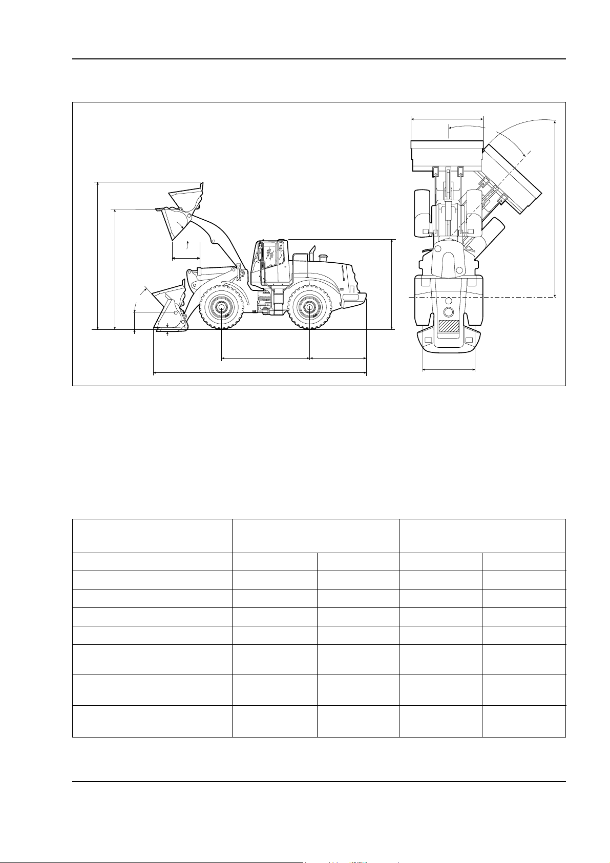
DIMENSIONS AND WEIGHT
0 - 19W130/W130TC
*
40˚
*
*
3828
44˚
380
Operating weight: 11.758 kg
Note –
Type of bucket
Machine arranged with 2.1 cu m bucket, tyres 20.5x25 filled and operator.
85
*
3290
2900 2425
*
With teeth and segments With suppl. cutting edge
1850
W130M0001
Dimensions in mm
* Please refer to the table
Bucket capacity m
Bucket weight kg 888 935 895 942
Bucket width mm 2540 2540 2500 2500
Dumping height at 45° m m 2761 2680 2794 2713
Dumping reach at 45° m m 1029 1118 991 1080
Max. length
(w/ bucket on ground) m m 7054 7179 7005 7129
Max. height
(w/ bucket raised) m m 5030 5039 5030 5039
Turning radius
(in transportation position) m 11.5 11.56 10.4 11.5
3
Carefully read personal and machine SAFETY PRECAUTIONS (at the beginning of this manual)
2.1 2.3 2.1 2.3
Page 26

0 - 20 W130/W130TC
Copyright © New Holland
–30 to 20 °C (-22 to 68 °F)
–10 to 50 °C (14 to 122 °F)
15W-40 –10 to 50 °C (14 to 122 °F)
GENERALITIES
– –20 to 50 °C (-4 to 122 °F)
–40 to 50 °C (-40 to 122 °F)
Spec. B-27
Grade 251H-EP
API CH-4
ACEA E2
API CF-4/SG
ACEA E3
TABLE OF FLUID CAPACITIES
Mastergold HSP*
LITRES (USG) SPECIFICATIONS (SAE) OF REFERENCE (°C)
ACEA E2
API CF-4/SG
ISO VG 46, DIN 51524
Item 1 and 2, QFH583/HD
TRX API GL4 SAE 80W-140 –20 to 50 °C (-4 to 122 °F)
rear 22
front 22
4.7 SC 35 – – –
0.2 (0.05) L BAR 134 – – –
ITEM QUANTITY FLUIDS OR LUBRICANT CLASSIFICATION VISCOSITY OUT DOOR TEMPERAT.
Carefully read personal and machine SAFETY PRECAUTIONS (at the beginning of this manual)
ENGINE + OIL FILTER 12. 5 Super Gold MIL-L-2104E 15W-40
RADIATOR 22 Agriflu ASTM D-5345 – –35 to 50 °C (-31 to 122 °F)
TRANSMISSION + FILTER 18. 5 Super Gold MIL-L-2104E 10W-30 –30 to 20 °C (-22 to 68 °F)
HYDRAULIC SYSTEM 63 (114 TOT.) HITECH 46
FUEL TANK 18.3 – – – Diesel fuel ASTM no. 2D
AXLES
GREASE FITTINGS – MG-2 –
COMPRESSOR
WINDSHIELD WASHER
AIR CONDITIONER
FLUID
In the event engine oil with "CH4" classification is used, the change interval can be prolonged to 500 hours providing that the outer temperature of operation
*
Oil quantities indicated are those required for periodical changes following the draining and filling procedures indicated in detail for each group.
does not exceed 38 °C (100 °F) and that the percentage of sulphur in the fuel does not exceed 0.5 %.
In the event of really heavy duty conditions, reduce the greasing intervals.
Page 27

GENERALITIES
Copyright © New Holland
UNITS OF MEASURE
CONVERSION FACTORS
Metric to U.S.
MULTIPLY BY TO OBTAIN
Area: sq. meter 10.763 91 square foot
hectare 2.471 05 acre
Force: newton 3.596 942 ounce force
newton 0.224 809 pound force
Length: millimeter 0.039 370 inch
meter 3.280 840 foot
kilometer 0.621 371 mile
Mass: kilogram 2.204 622 pound
Mass/Area: kilogram/hectare 0.000 466 ton/acre
0 - 21W130/W130TC
Mass/Energy: g/kW/hr. 0.001 644 lbs/hp/hr.
Mass/Volume: kg/cubic meter 1.685 555 lb/cubic yd.
Power: kilowatt 1.341 02 horsepower
Pressure: kilopascal 0.145 038 lb/sq. inch
bar 14.50385 lb/sq. inch
Temperature: degree C 1.8 x C +32 degree F
Torque: newton meter 8.850 748 lb/inch
newton meter 0.737 562 lb/foot
Velocity: kilometer/hr. 0.621 371 miles/hr.
Volume: cubic centimeter 0.061 024 cubic inch
cubic meter 35.314 66 cubic foot
cubic meter 1.307 950 cubic yd.
milliliter 0.033 814 ounce (US fluid)
litre 1.056 814 quart (US liquid)
litre 0.879 877 quart (Imperial)
litre 0.264 172 gallon (US liquid)
litre 0.219 969 gallon (Imperial)
Volume/Time: litre/min. 0.264 172 gallon/min. (US liquid)
litre/min. 0.219 969 gallon/min. (Imperial)
Carefully read personal and machine SAFETY PRECAUTIONS (at the beginning of this manual)
Page 28

0 - 22 W130/W130TC
Copyright © New Holland
GENERALITIES
U.S. to Metric
MULTIPLY BY TO OBTAIN
Area: sq. foot 0.092 903 square meter
acre 0.404 686 hectare
Force: ounce force 0.278 014 newton
pound force 4.448 222 newton
Length: inch 25.4 * millimeter
foot 0.304 8 * meter
mile 1.609 344 * kilometer
Mass: pound 0.453 592 kilogram
ounce 28.35 gram
Mass/Area: ton/acre 2241 702 kilogram/hectare
Mass/Energy: lb/hp/hr 608.277 4 gr/kW/hr
Mass/Volume: lb/cubic yd. 0.593 276 kg/cubic meter
Power: horsepower 0.745 700 kilowatt
Pressure: lbs/sq. in. 6.894 757 kilopascal
lbs/sq. in. 0.069 bar
lbs/sq. in. 0.070 303 kg/sq. cm
Temperature: degree F 1.8 F - 32 degree C
Torque: pound/inch 0.112 985 newton meter
pound/foot 1.355 818 newton meter
Velocity: miles/hr. 1.609 344 * kilometer/hr.
Volume: cubic inch 16.387 06 cubic centimeter
cubic foot 0.028 317 cubic meter
cubic yard 0.764.555 cubic meter
ounce (US fluid) 29.573 53 milliliter
quart (US liquid) 0.946 353 litre
quart (Imperial) 1.136 523 litre
gallon (US) 3.785 412 litre
gallons (Imperial) 4.546 092 litre
Volume/Time: gallon/min. 3.785 412 litre/min.
* = exact
Carefully read personal and machine SAFETY PRECAUTIONS (at the beginning of this manual)
Page 29
GENERALITIES
Copyright © New Holland
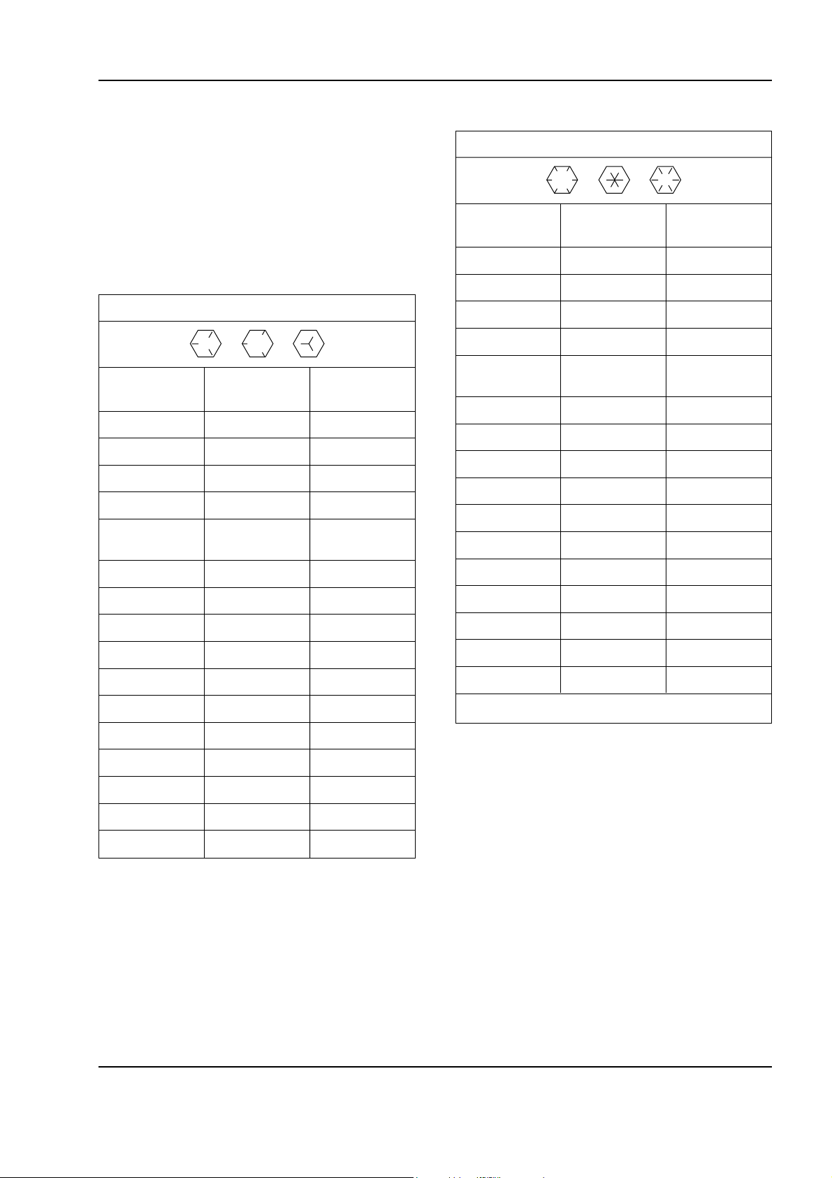
STANDARD TORQUE SPECIFICATION
0 - 23W130/W130TC
TORQUE SPECIFICATIONS - DECIMAL HARDWARE
Use the torques in this chart when special torques
are not given. These torques apply to fasteners with
both UNC and UNF threads as received from suppliers dry, or when lubricated with engine oil. Not applicable if special graphitiesm Molydisulfide greases, or
other extreme pressure lubricants are used.
Grade 5 Bolts, Nuts, and Studs
Size
1/4 inch 108 to 132 12 to 15
5/1 6 204 to 252 23 to 28
3/8 inch 420 to 504 48 to 57
Size
7/16 inch 54 to 64 73 to 87
Pound- Newton
Inches metres
Pound- Newton
Feet metres
Grade 8 Bolts, Nuts, and Studs
Size
1/4 inch 144 to 180 16 to 20
5/1 6 288 to 348 33 to 39
3/8 inch 540 to 648 61 to 73
Size
7/16 inch 70 to 84 73 to 87
1/2 inch 110 to 132 149 to 179
9/16 inch 160 to 192 217 to 260
5/8 inch 220 to 264 298 to 358
3/4 inch 380 to 456 515 to 618
7/8 inch 600 to 720 814 to 976
1.0 inch 900 to 1080 1220 to 1465
Pound- Newton
Inches metres
Pound- Newton
Feet metres
1/2 inch 80 to 96 109 to 130
9/16 inch 110 to 132 149 to 179
5/8 inch 150 to 180 203 to 244
3/4 inch 270 to 324 366 to 439
7/8 inch 400 to 480 542 to 651
1.0 inch 580 to 696 787 to 944
1-1/8 inch 800 to 880 1085 to 1193
1-1/4 inch 1120 to 1240 1519 to 1681
1-3/8 inch 1460 to 1680 1980 to 2278
1-1/2 inch 1940 to 2200 2631 to 2983
1-1/8 inch 1280 to 1440 1736 to 1953
1-1/4 inch 1820 to 2000 2468 to 2712
1-3/8 inch 2380 to 2720 3227 to 3688
1-1/2 inch 3160 to 3560 4285 to 4827
Note –
Use thick nuts with Grade 8 bolts.
Carefully read personal and machine SAFETY PRECAUTIONS (at the beginning of this manual)
Page 30

0 - 24 W130/W130TC
Copyright © New Holland
GENERALITIES
TORQUE SPECIFICATIONS - METRIC HARDWARE
Use the following torques when specifications are not
given.
These values apply to fasteners with coarse threads
as received from supplier, plated or unplated, or when
lubricated with engine oil. These values do not apply
if graphite or Molydisulfide grease or oil is used.
Grade 8.8 Bolts, Nuts, and Studs
8.8
Size
Pound- Newton
Inches metres
M4 24 to 36 3 to 4
M5 60 to 72 7 to 8
M6 96 to 108 11 to 12
M8 228 to 276 26 to 31
M1 0 456 to 540 52 to 61
Grade 10.9 Bolts, Nuts, and Studs
10.9
Size
Pound- Newton
Inches metres
M4 36 to 48 4 to 5
M5 84 to 96 9 to 11
M6 132 to 156 15 to 18
M8 324 to 384 37 to 43
Size
Pound- Newton
Feet metres
M1 0 54 to 64 73 to 87
M1 2 93 to 112 125 to 150
M1 4 149 to 179 200 to 245
M1 6 230 to 280 310 to 380
M2 0 450 to 540 610 to 730
Size
Pound- Newton
Feet metres
M1 2 66 to 79 90 to 107
M1 4 106 to 127 144 to 172
M1 6 160 to 200 217 to 271
M2 0 320 to 380 434 to 515
M2 4 500 to 600 675 to 815
M30 920 to 1100 1250 to 1500
M36 1600 to 1950 2175 to 2600
M24 780 to 940 1050 to 1275
M30 1470 to 1770 2000 to 2400
M36 2580 to 3090 3500 to 4200
Grade 12.9 Bolts, Nuts, and Studs
12.9
Usually the torque values specified for grade 10.9
fasten can be used satisfactorily on grade 12.9 fasteners.
Carefully read personal and machine SAFETY PRECAUTIONS (at the beginning of this manual)
Page 31

GENERALITIES
Copyright © New Holland
0 - 25W130/W130TC
TORQUE SPECIFICATIONS - STEEL HYDRAULIC
FITTINGS
Tube OD Thread Pound- Newton
Hose ID Size Inches metres
37 Degree Flare Fitting
1/4 inch 7/ 16-20 72 to 144 8 to 16
6.4 mm
5/16 inch 1/2-20 96 to 192 11 to 12
7.9 mm
3/8 inch 9/ 16-18 120 to 300 14 to 34
9.5 mm
1/2 inch 3/4-16 180 to 504 20 to 57
12.7 mm
5/8 inch 7/8-14 300 to 696 34 to 79
15.9 mm
Tube OD Thread Pound- Newton
Hose ID Size Inches metres
3/4 inch 1-1/16-12 40 to 80 54 to 108
19.0 mm
7/8 inch 1-3/16-12 60 to 100 81 to 135
22.2 mm
1.0 inch 1-5/16-12 75 to 117 102 to 158
25.4 mm
1-1/4 inch 1-5/8-12 125 to 165 169 to 223
31.8 mm
1-1/2 inch 1-7/8-12 210 to 250 285 to 338
38.1 mm
Tube OD Thread Pound- Newton
Hose ID Size Inches metres
Straight Threads with O-ring
1/4 inch 7/1 6- 20 144 to 228 16 to 26
6.4 mm
5/16 inch 1/2-20 192 to 300 22 to 34
7.9 mm
3/8 inch 9/1 6- 18 300 to 480 34 to 54
9.5 mm
1/2 inch 3/4-16 540 to 804 57 to 91
12.7 mm
Tube OD Thread Pound- Newton
Hose ID Size Inches metres
5/8 inch 7/8-14 58 to 92 79 to 124
15.9 mm
3/4 inch 1-1/16-12 80 to 128 108 to 174
19.0 mm
7/8 inch 1-3/16-12 100 to 160 136 to 216
22.2 mm
1.0 inch 1-5/16-12 117 to 187 159 to 253
25.4 mm
1-1/4 inch 1-5/8-12 165 to 264 224 to 357
31.8 mm
1-1/2 inch 1-7/8-12 250 to 400 339 to 542
38.1 mm
Split Flange Mounting Bolts
Size
5/16-18 180 to 240 20 to 27
3/8-16 240 to 300 27 to 34
7/16-14 420 to 540 47 to 61
Size
1/2-13 55 to 65 74 to 88
5/8-11 140 to 150 190 to 203
Pound- Newton
Inches metres
Pound- Newton
Feet metres
Carefully read personal and machine SAFETY PRECAUTIONS (at the beginning of this manual)
Page 32

0 - 26 W130/W130TC
Copyright © New Holland
GENERALITIES
TORQUE SPECIFICATIONS - STEEL HYDRAULIC FITTINGS
Nom
SAE
Dash Size Inches metres Size Inches metres
Tube OD
Thread Pound- Newton Thread Pound- Newton
Size
O-ring Face Seal End
O-ring Boss End
Fitting or Lock Nut
-4 1/4 inch 9/16-18 120 to 144 14 to 16 7/16-20 204 to 240 23 to 27
6.4 mm
-6 3/8 inch 11/16-16 216 to 240 24 to 27 9/16-18 300 to 360 34 to 41
9.5 mm
-8 1/2 inch 13/16-16 384 to 480 43 to 54 3/4-16 540 to 600 61 to 68
12.7 mm
Thread Pound- Newton
Size Inches metres
-1 0 5/8 inch 1-14 552 to 672 62 to 76 7/8-14 60 to 65 81 to 88
15.9 mm
Nom 1-1/16/12 85 to 90 115 to 122
SAE
Dash Size Inches metres
Tube OD
Thread Pound- Newton
1-3/16-12 95 to 100 129 to 136
Size
-1 2 3/4 inch 1-3/16-12 65 to 80 90 to 110 1-5/16-12 115 to 125 156 to 169
19.0 mm
-1 4 7/8 inch 1-3/16-12 65 to 80 90 to 110 1-5/18-12 150 to 160 203 to 217
22.2 mm
-1 6 1.0 inch 1-7/16-12 92 to 105 125 to 140 1-7/8-12 190 to 200 258 to 271
25.4 mm
-2 0 1-1/4 inch 1-11/16-12 125 to 140 170 to 190
31.8 mm
-2 4 1-1/2 inch 2-12 150 to 180 200 to 254
38.1 mm
Carefully read personal and machine SAFETY PRECAUTIONS (at the beginning of this manual)
Page 33

GENERALITIES
Copyright © New Holland
LOCTITE PRODUCT CHART
0 - 27W130/W130TC
Form a Gasket (works with oil,
fuel or grease) Pliable
Primer Description
Fixture/Full Cure
(Steel/Steel) Time
Working
Temperature
Range-Farenheit
Low Strength Threadlocker
(Small Screws)
Surface Insensitive Gen
Instant Adhesive
Similar Gap Strength
Products (In Inches) (Steel/Steel)
Product Color
80 Yellow Fast N/A Weatherstrip Adhesive
#3 Dark Brown 24 hr N/A
123 Clear N/A N/A Parts Cleaner Fluid
220 Blue 2 9 0 0.003 57/143 in lbs -65 to +250 6 min/24 hrs 7 47 Wicking Threadlocker
221 Purple 2 2 2 0.005 75/44 in lbs -65 to +300 2 min/24 hrs 74 7 Low Strength Threadlocker
222 Purple 0.005 53/30 in lbs -65 to +300 20 min/24 hrs 76 4
225 Brown 2 2 2 0.010 45/25 in lbs -65 to +300 7 min/24 hrs 74 7 Low Strength Threadlocker
242 Blue 0.005 80/50 in lbs -65 to +300 10 min/24 hrs 76 4 Medium Strength Threadlocker
262 Re d 271 0.005 160/190 in lbs -65 to +300 5 min/24 hrs 74 7 High Strength Threadlocker
270 Green 271 0.007 160/320 in lbs -65 to +300 3 min/24 hrs 74 7 High Strength Threadlocker
271 Re d 262 0.007 160/320 in lbs -65 to +300 10 min/24 hrs 76 4 High Strength Threadlocker
272 Re d 620 0.007 180/220 in lbs -65 to +450 30 min/24 hrs 76 4 High Temperature, High Strength
275 Green 277 0.010 210/300 in lbs -65 to +300 3 min/24 hrs 74 7 High Strength Threadlocker
277 Re d 0.010 225/300 in lbs -65 to +300 60 min/24 hrs 76 4 High Strength Threadlocker
290 Green 0.003 85/350 in lbs -65 to +300 6 min/24 hrs 76 4 Wicking Threadlocker
*404 Clear 495 0.006 3200 psi -65 to +180 30 sec/24 hrs NA Instant Adhesive
*406 Clear 0.004 3200 psi -65 to +180 15 sec/24 hrs N/A Surface Insensitive Adhesive
*409 Clear 454 0.008 2500 psi -65 to +180 50 sec/24 hrs N/A Gap Instant Adhesive
*414 Clear 0.006 2500 psi -65 to +180 30 sec/24 hrs N/A Instant Adhesive
*415 Clear 454 0.010 2500 psi -65 to +180 50 sec/24 hrs N/A Gap Filling Instant Adhesive (Metals)
*416 Clear 454 0.010 2500 psi -65 to +180 50 sec/24 hrs N/A Gap Filling Instant Adhesive (Plastics)
*420 Clear 0.002 2500 psi -65 to +180 15 sec/24 hrs N/A Wicking Instant Adhesive
*422 Clear 454 0.020 2800 psi -65 to +180 60 sec/24 hrs N/A Gap Filling Instant Adhesive
*430 Clear 0.005 2500 psi -65 to +180 20 sec/24 hrs N/A Metal Bonding Adhesive
*445 White/Black 0.250 2000 psi -65 to +180 5 min/24 hrs N/A Fast Setting 2 Part Epoxy
*454 Clear 0.010 3200 psi -65 to +180 15 sec/24 hrs N/A
*495 Clear 0.004 2500 psi -65 to +180 20 sec/24 hrs N/A General Purpose Instant Adhesive
Carefully read personal and machine SAFETY PRECAUTIONS (at the beginning of this manual)
50 4 Brt Orange 515 0.030 750 psi -65 to +300 90 min/24 hrs Non e Rigid Gasket Eliminator
50 9 Light Blue 0.020 750 psi -65 to +320 6 hr/72 hrs 764 Flange Sealant
*496 Clear 0.005 2500 psi -65 to +180 20 sec/24 hrs N/A Metal Bonding Adhesive
510 Re d 0.020 1000 psi -65 to +400 30 min/24 hrs 76 4 High Temperature, Gasket Eliminator
515 Purple 0.010 750 psi -65 to +300 1 hr/24 hrs 7 6 4 Gasket Eliminator 515
* Products 404-496 (except for #445) are all instant adhesives (super glues) they differ mostly in viscosity
Page 34

0 - 28 W130/W130TC
Copyright © New Holland
GENERALITIES
Primer Description
Fixture/Full Cure
(Steel/Steel) Time
Working
Temperature
Range-Farenheit
Low Strength Pneumatic/Hydraulic
Sealant
High Temperature Retaining
Compound
Similar Gap Strength
Products (In Inches) (Steel/Steel)
518 Re d 515 0.030 500 psi -65 to +300 1 hr/24 hrs 7 64 Gasket Eliminator 518 for Aluminum
Product Color
Carefully read personal and machine SAFETY PRECAUTIONS (at the beginning of this manual)
545 Purple N/A 25/20 in lbs -65 to +300 4 hrs/24 hrs 74 7
542 Brown 569 N/A 132/92 in lbs -65 to +300 2 hrs/24 hrs 74 7 Hydraulic Sealant
549 Orange 5 0 4 0.020 2500 psi -65 to +300 2 hrs/24 hrs 747 Instant Seal Plastic Gasket
554 Re d 277 0.015 240/240 in lbs -65 to +300 2 to 4 hrs/24 hrs 764 Refrigerant Sealant
567 White 592 N/A 500 psi -65 to +400 4 hrs/24 hrs 76 4 Pipe Sealant for Stainless Steel
568 Orange 2 7 7 0.015 2500 psi -65 to +300 12 hrs/24 hrs 76 4 Plastic Gasket
569 Brown 545 0.010 40/25 in lbs -65 to +300 1 hr/24 hrs 764 Hydraulic Sealant
570 Brown 592 N/A 25/40 in lbs -65 to +300 6 hrs/72 hrs 7 6 4 Steam Sealant
571 Brown 592 0.015 40/20 in lbs -65 to +300 2 to 4 hrs/24 hrs 764 Pipe Sealant
572 White 578.575 N/A 80/27 in lbs -65 to +300 24 hrs/72 hrs N on e Gasketing
592 White 0.020 500 psi -65 to +400 4 hrs/72 hrs 736 Pipe Sealant with Teflon
593 Black 0.250 400 psi -95 to +400 30 min/24 hrs N/A RTV Silicone
601 Green 609 0.005 3000 psi -65 to +300 10 min/24 hrs 764 Current PIN #609
609 Green 0.005 3000 psi -65 to +300 10 min/24 hrs 76 4 General Purpose Retaining Compound
620 Green 640 0.015 3000 psi -65 to +450 30 min/24 hrs 747
635 Green 680 0.010 4000 psi -65 to +300 1 hr/24 hrs 74 7 High Strength Retaining Compound
638 Green 680 0.015 4100 psi -65 to +300 10 min/24 hrs 7 47 High Strength Retaining Compound
640 Green 620 0.007 3000 psi -65 to +400 1 hr/24 hrs 747 High Temperature Retaining Compound
660 Silver 0.020 3000 psi -65 to +300 20 min/24 hrs 764 Quick Metal
675 Green 609 0.005 3000 psi -65 to +300 20 min/24 hrs 7 47 General Purpose Retaining Compound
680 Green 635 0.015 4000 psi -65 to +300 10 min/24 hrs 7 47 High Strength Retaining Compound
706 Clear 7 55 N/A N/A N/A N/A N/A Cleaning Solvent
70 7 Ambe r N/A N/A N/A N/A N/A Activator for Structural Adhesives
73 6 Amb er N/A N/A N/A N/A N/A Primer NF
73 8 Ambe r N/A N/A N/A N/A N/A Depend Activator
747 Yellow N/A N/A N/A N/A N/A N/A Primer T
751 Clear N/A N/A N/A N/A N/A Activator for Structural Adhesives
755 Clear N/A N/A N/A N/A N/A Cleaning Solvent
764 Green N/A N/A N/A N/A N/A Primer N
767 Silver N/A N/A -65 to +1600 N/A N/A Anti-Seize Lubricant
Page 35

SECTION 1
Copyright © New Holland
ENGINE
INDEX
PARAGRAPH SUBJECT PAGE
1.1 GENERAL FEATURES ......................................................................................... 1-1
1.2 DESCRIPTION OF MAIN GROUPS ..................................................................... 1-3
Cylinder head.................................................................................................... 1-8
Valves and valve seats..................................................................................... 1-9
Valve guides ..................................................................................................... 1-10
Engine flywheel ................................................................................................ 1-11
1.3 LUBRICATION ...................................................................................................... 1-13
1.4 OPERATION DESCRIPTION FUEL SYSTEM ...................................................... 1-15
1.5 TROUBLESHOOTING GUIDE .............................................................................. 1-25
1.6 ENGINE OVERHAUL ON BENCH......................................................................... 1-39
Disassembly of engine ..................................................................................... 1-39
Removal of injection pump................................................................................ 1-42
Removal of rocker arm group............................................................................ 1-44
Repair interventions on cylinder group .............................................................. 1-47
Timing .............................................................................................................. 1-49
Bushes ............................................................................................................. 1-50
Tappets............................................................................................................. 1-51
Crankshaft........................................................................................................ 1-52
Conrods ............................................................................................................ 1-60
Setting the timing ............................................................................................. 1-65
Engine flywheel ................................................................................................ 1-67
Replacing the injectors ..................................................................................... 1-81
Adjusting the valve clearance ........................................................................... 1-82
1.7 TOOLING.............................................................................................................. 1-85
Page 36

Copyright © New Holland
Page 37
ENGINE
Copyright © New Holland
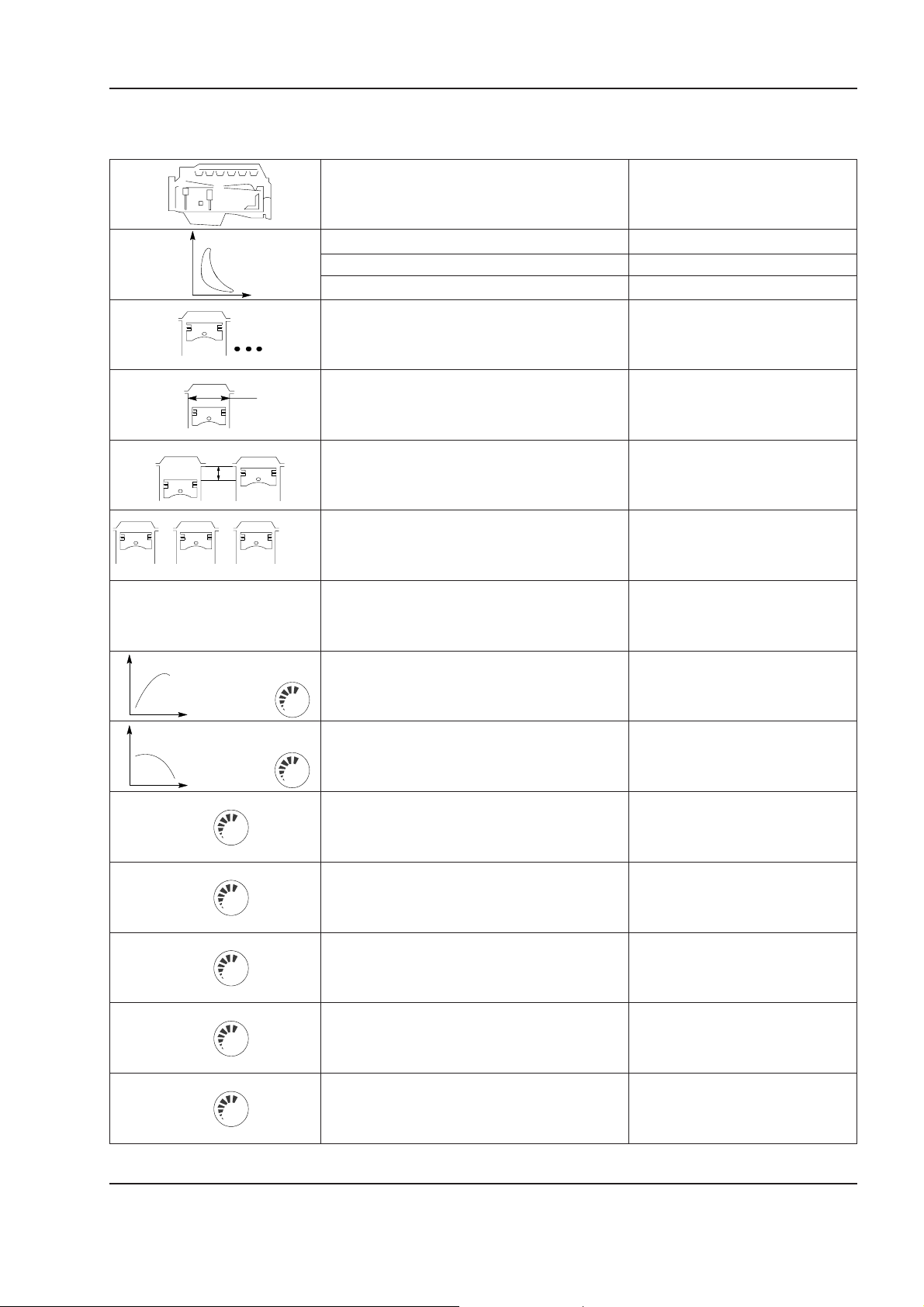
1.1 GENERAL FEATURES
Type F4GE0684F
Cycle Diesel 4-stroke
Intake Turbocharged w/aftercooler
Injection Direct
Number of cylinders 6 in-line
Bore mm 104
Stroke mm 13 2
1 - 1W130/W130TC
+++..=
Total displacement cm
∂
Compression ratio 17 : 1
Maximum power kW 111
Maximum torque (kgm) Nm 690
Engine low idle @ rpm 1020 to 1080
Engine high idle @ rpm 2060 to 2180
Maximum speed
hydraulic stall
3
(HP) 148
@ rpm 2000
@ rpm 1200
@ rpm 1925 to 2085
6700
Maximum speed
transmission stall
Maximum speed
total stall (hydr. + transmission)
Carefully read personal and machine SAFETY PRECAUTIONS (at the beginning of this manual)
@ rpm 1925 to 2085
@ rpm 1340 to 1650
Page 38
1 - 2 W130/W130TC
Copyright © New Holland
ENGINE
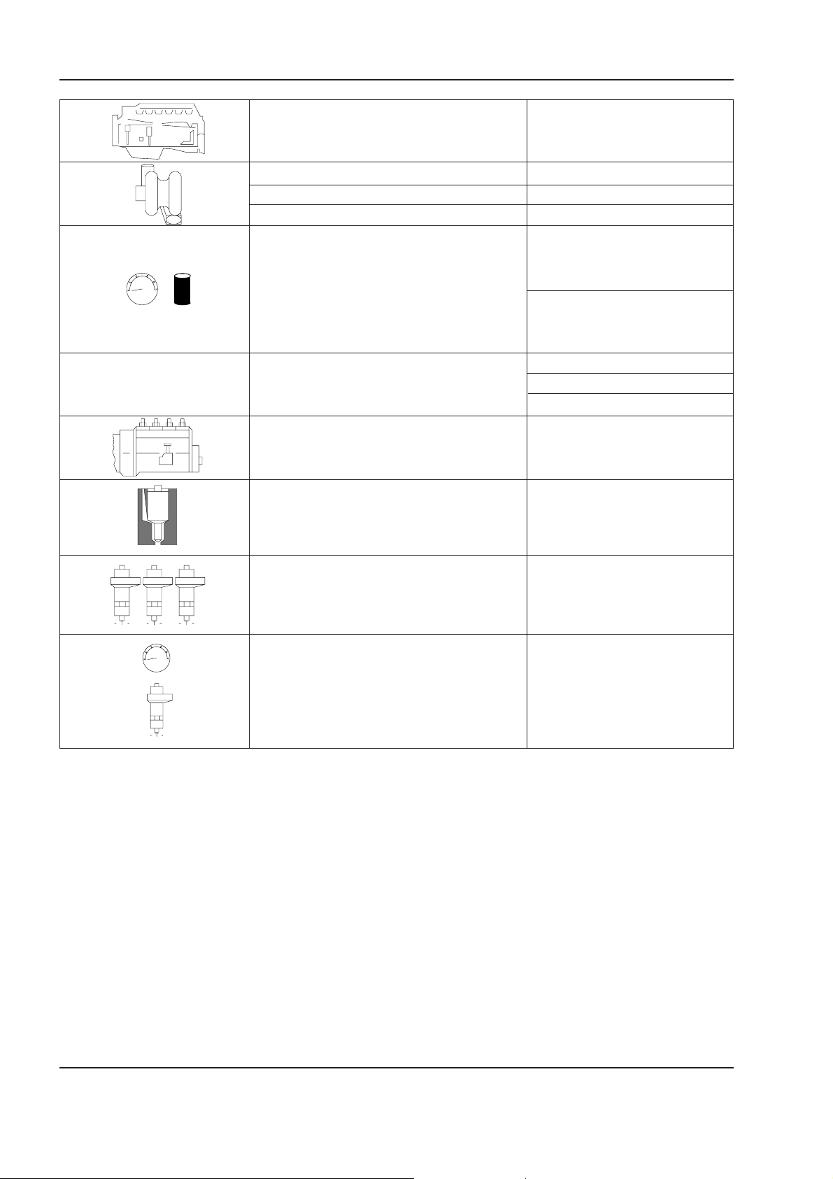
Type F4GE0684F
TURBOCHARGING w/ AFTERCOOLER
CHARGING PRESSURE 1.10 ± 0.1 bar
Turbocharger type: HOLSET HX35W
LUBRICATION Forced by gear pump,
pressure relief valve,
Oil pressure oil filter
bar
with hot engine:
at low idle bar 1.2
at high idle ba r 3.8
COOLING Liquid
Water pump drive: Belt
Thermostat starts opening at: °C (°F) 81 ± 2 (178 ± 3.6)
INJECTION
type Bosch
VE4/ 12F 1100
Injector nozzles type DSLA 145 P603
Firing ord e r 1 - 3 - 4 - 2
bar
Injection pressure bar 24 5
Carefully read personal and machine SAFETY PRECAUTIONS (at the beginning of this manual)
Page 39
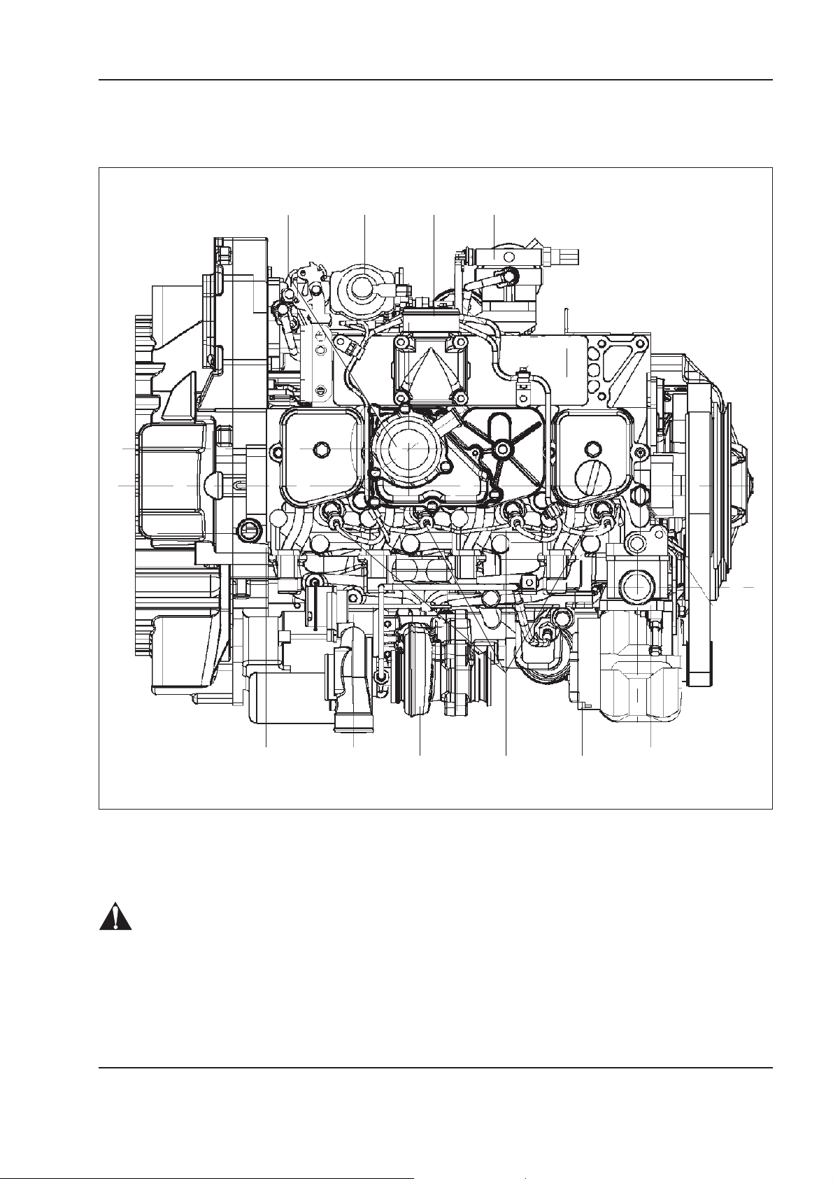
Upper view
Copyright © New Holland
ENGINE
1.2 DESCRIPTION OF MAIN GROUPS
D E F G
1 - 3W130/W130TC
Upper view
A. Alternator - B. Injectors - C. Turbocharger - D. Blow-by - E. Injection pump - F. Intake manifold - G. Fuel filter.
WARNING
Due to application requirements, some auxiliary groups can be located in different positions with respect
to what illustrated in this section of the manual.
C AB
W110R0096
Carefully read personal and machine SAFETY PRECAUTIONS (at the beginning of this manual)
Page 40
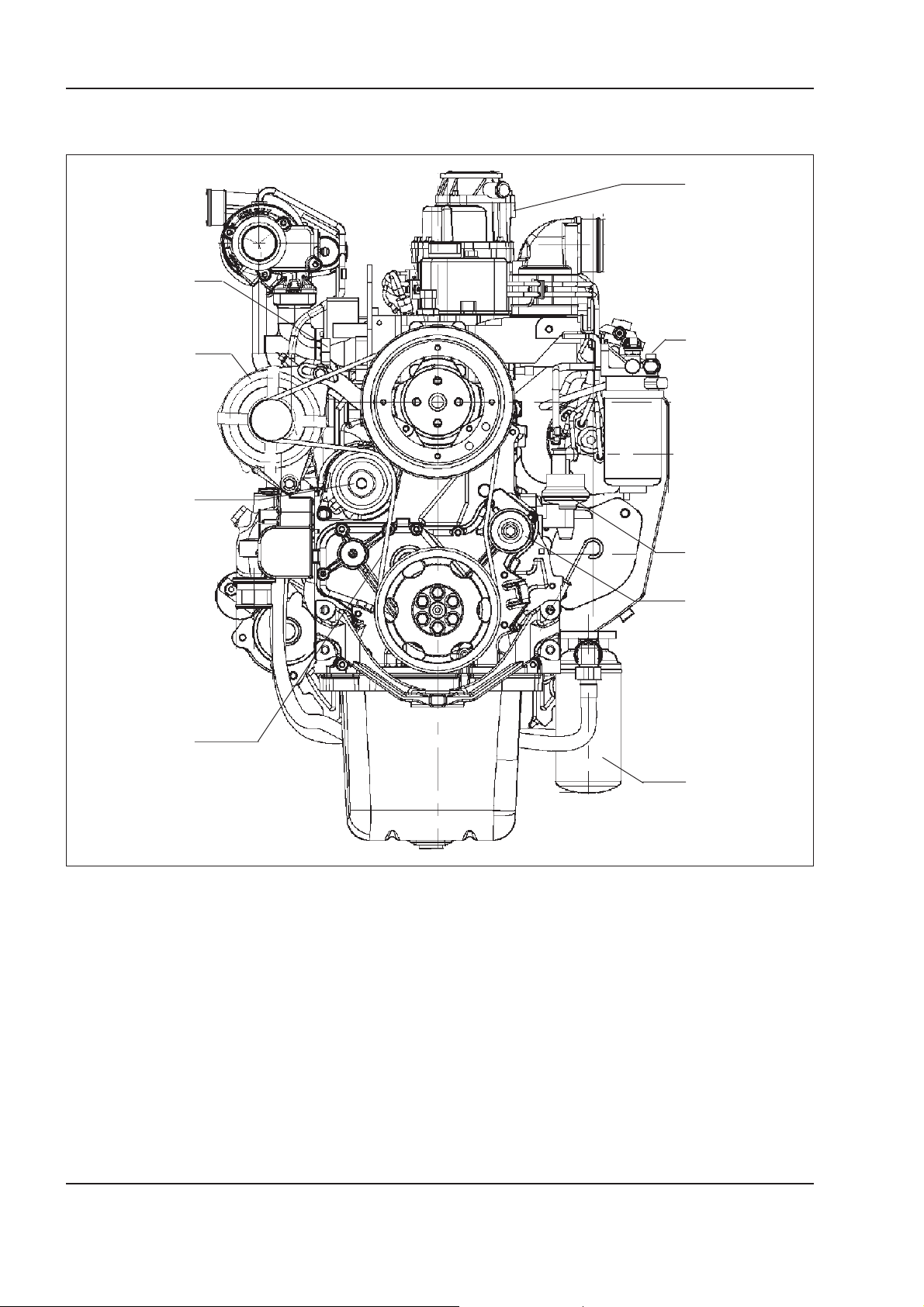
1 - 4 W130/W130TC
Copyright © New Holland
ENGINE
Front view
A
I
H
B
G
C
D
F
E
Front view
A. Blow-by - B. Fuel filter - C. Fuel pump - D. Idle pulley - E. Oil filter - F. Poly-V belt - G. Water pump - H. Alternator -
I. Thermostat.
Carefully read personal and machine SAFETY PRECAUTIONS (at the beginning of this manual)
W110R0097
Page 41
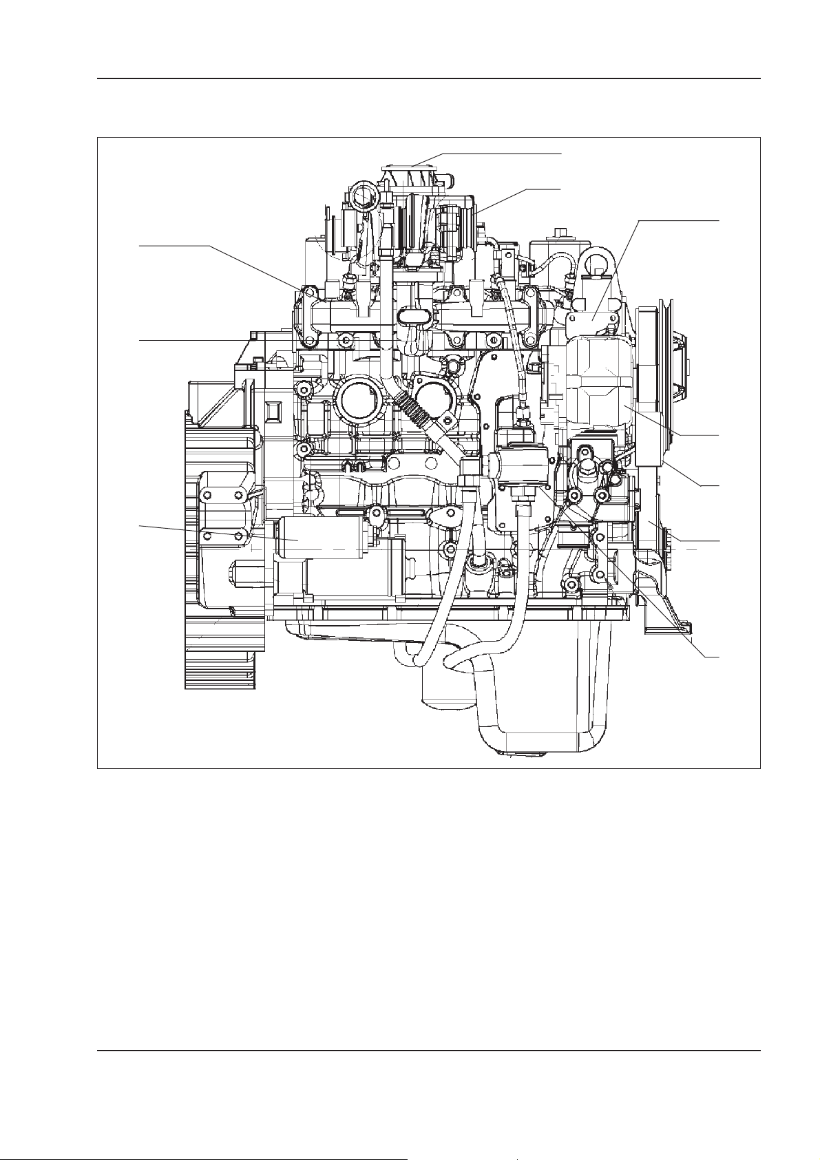
Right side view
Copyright © New Holland
L
I
ENGINE
1 - 5W130/W130TC
A
B
C
D
E
H
F
G
W110R0098
Right side view
A. Blow-by - B. Turbocharger - C. Thermostat - D. Alternator - E. Water pump - F. Poly-V belt - G. Oil filter connection -
H. Starter motor - I. Oil discharge pipe from turbocharger - L. Exhaust manifold.
Carefully read personal and machine SAFETY PRECAUTIONS (at the beginning of this manual)
Page 42
1 - 6 W130/W130TC
Copyright © New Holland
ENGINE
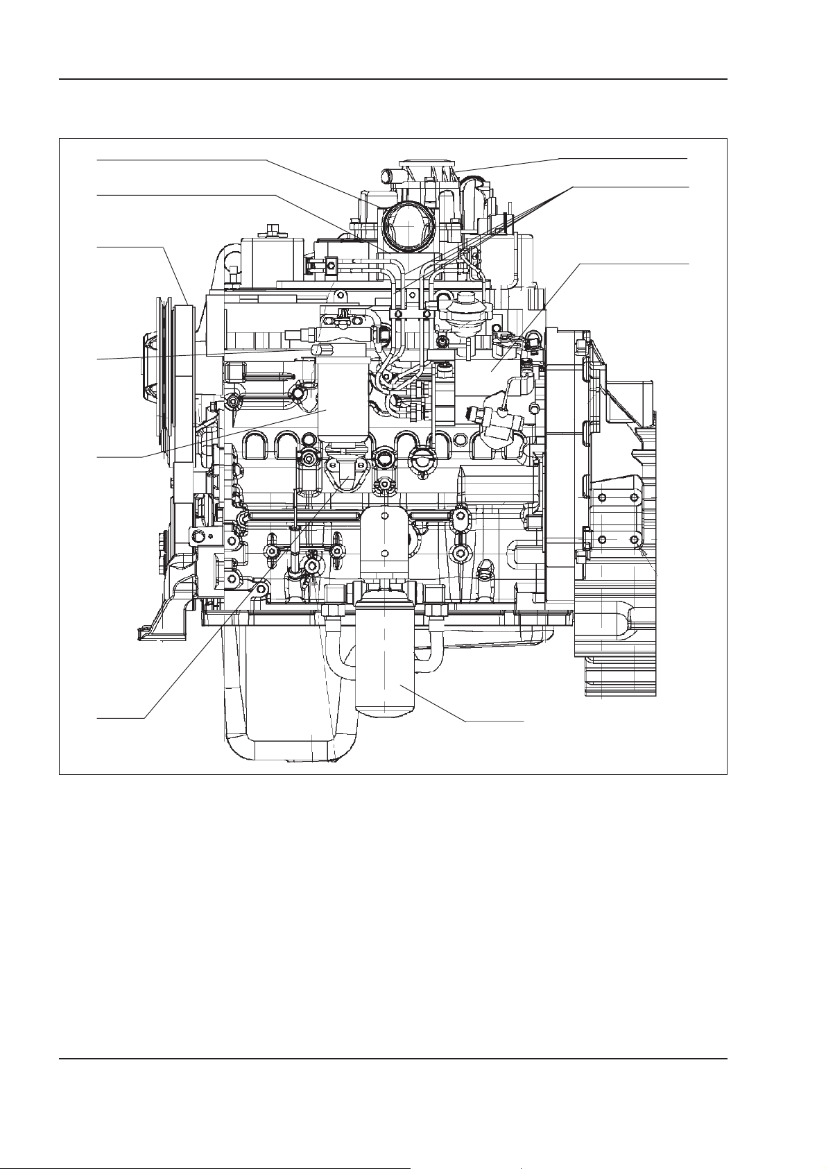
Left side view
L
I
A
B
H
C
G
F
G
E
D
W110R0099
Left side view
A. Blow-by - B. Injector fuel piping - C. Injection pump - D. Oil filter - E. Fuel pump - F. Fuel filter - G. Fuel heater -
H. Poly-V belt - I. Air heater (optional) - L. Intake manifold.
Carefully read personal and machine SAFETY PRECAUTIONS (at the beginning of this manual)
Page 43
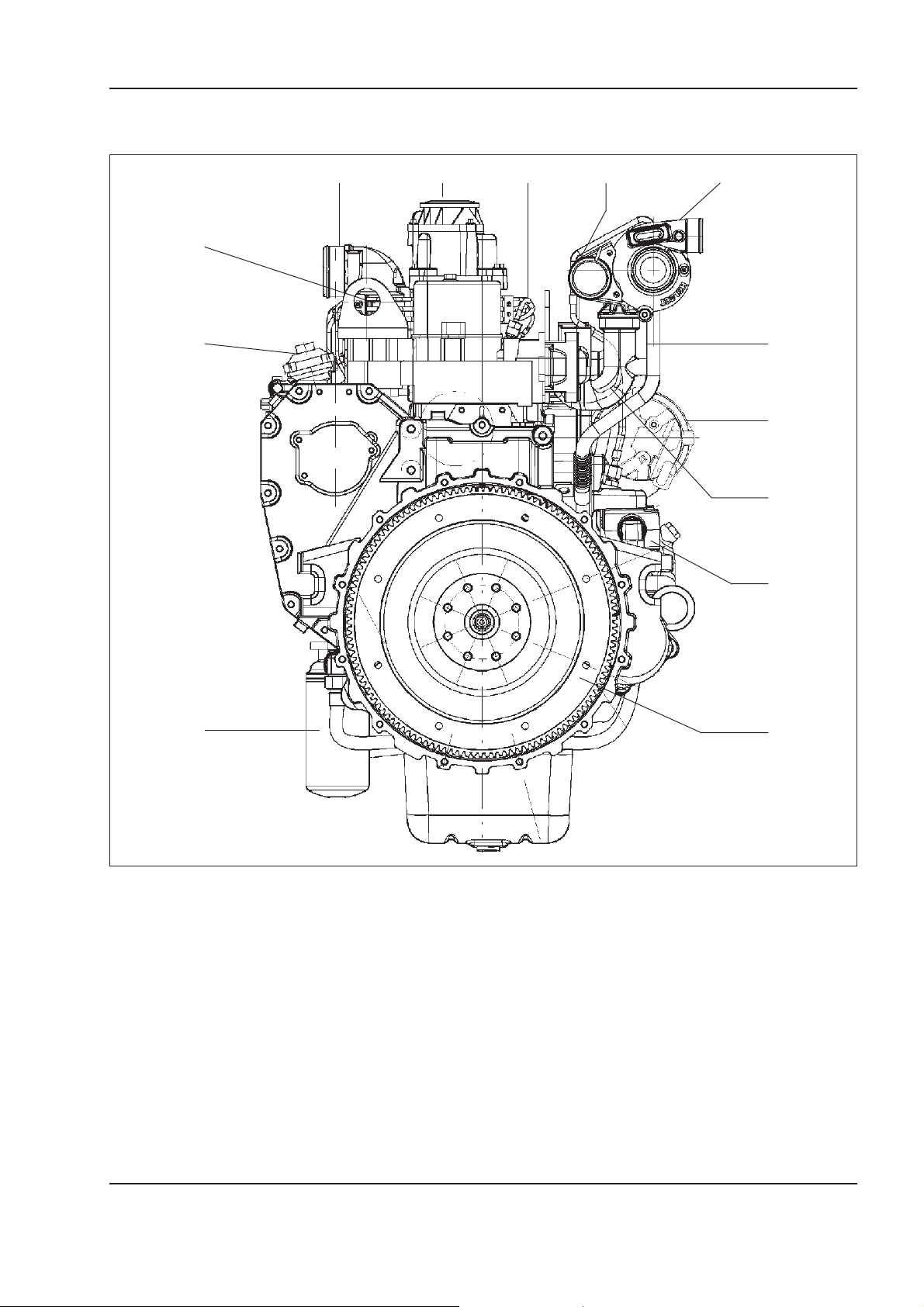
Rear view
Copyright © New Holland
ENGINE
1 - 7W130/W130TC
O A B C D
N
M
E
F
G
H
L
I
Rear view
A. Blow-by - B. Injector fuel piping - C. WASTGATE valve - D. Turbocharger - E. Oil discharge pipe from turbocharger -
F. Alternator - G. Exhaust manifold - H. Starter motor - I. Engine flywheel - L. Oil filter - M. Injection pump - N. Air heater
(Optional) - O. Intake manifold.
W110R0100
Carefully read personal and machine SAFETY PRECAUTIONS (at the beginning of this manual)
Page 44
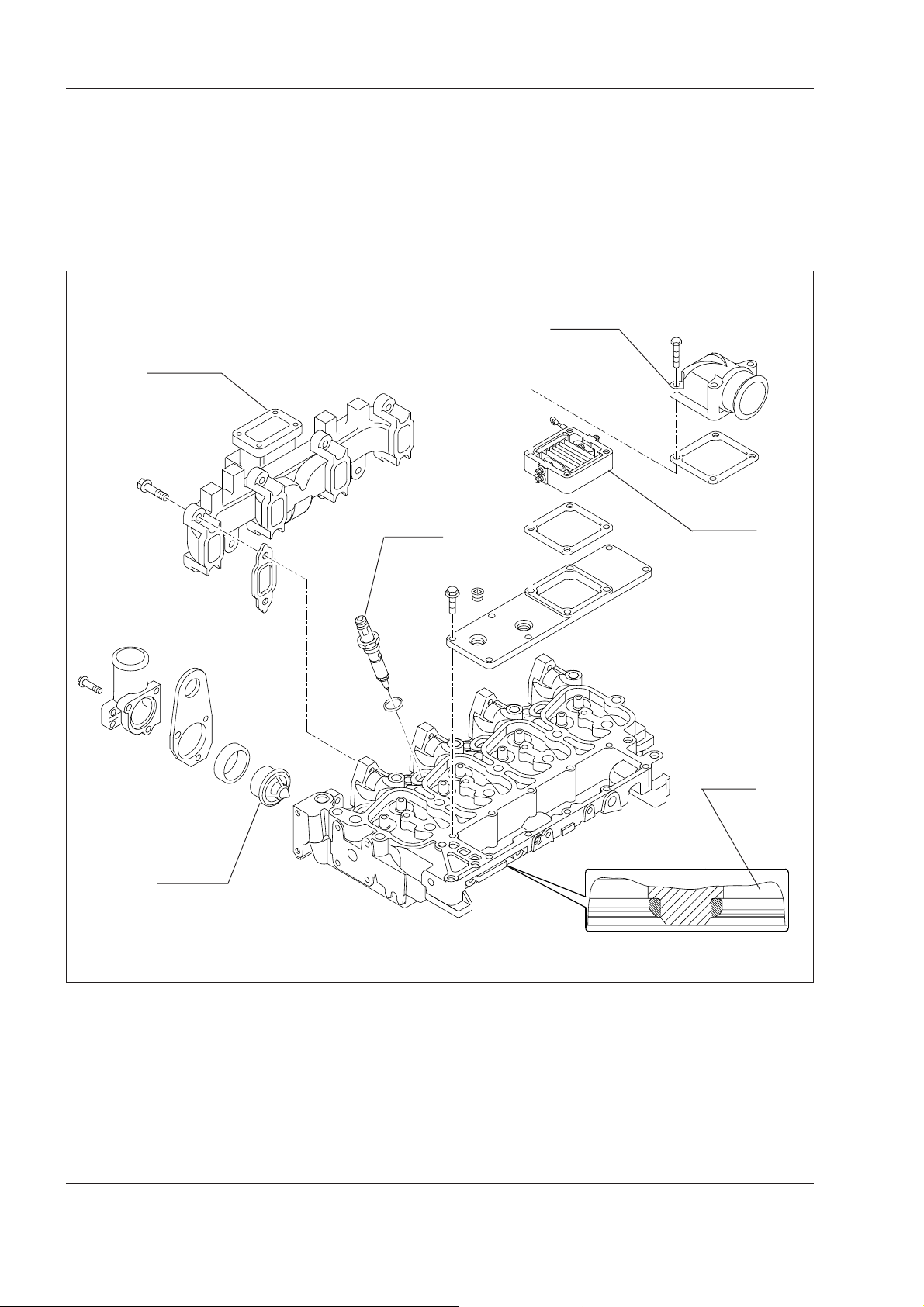
1 - 8 W130/W130TC
Copyright © New Holland
ENGINE
Cylinder head
On the cast iron made cylinder head, the seats of the
following components are made:
• added valve seats 4;
• injector 6;
• thermostat 5.
1
Also on the heads are fitted
• single block exhaust manifold 1;
• intake valve 2 with seat for cold starting air heater
3.
2
6
(OPTIONAL)
3
5
Detail of cylinder heads with added valve seats
Carefully read personal and machine SAFETY PRECAUTIONS (at the beginning of this manual)
4
W110R0101
Page 45
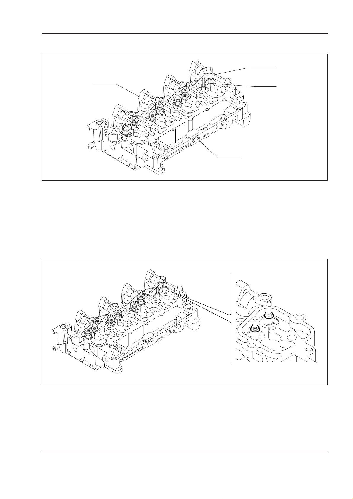
Valves and valve seats
Copyright © New Holland
ENGINE
1 - 9W130/W130TC
2
S
A. Intake side - S. Exhaust side - 1. Intake valve - 2. Exhaust valve.
The valve seats added on the cylinder heads have an
angle of:
- 45° for exhaust valves
Exhaust valves 2 differ from the intake valves for
the presence of a single groove at the tip of the
stem.
- 60° for intake valves
1
G
W110R0102
The figure indicates the oil seals installed on the valve stems.
W110R0103
Carefully read personal and machine SAFETY PRECAUTIONS (at the beginning of this manual)
Page 46
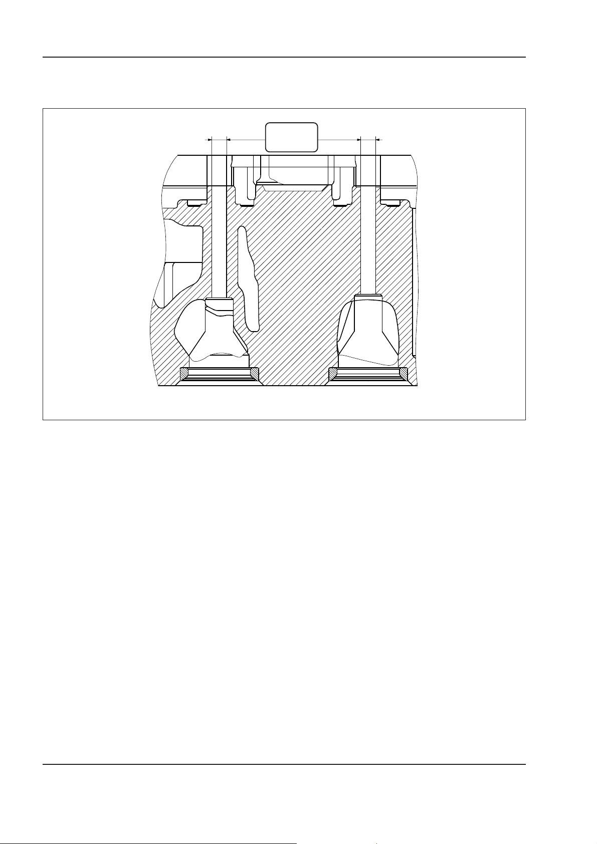
1 - 10 W130/W130TC
Copyright © New Holland
ENGINE
Valve guides
The valve guides are not machined.
8.019 mm
8.039 mm
INTAKE EXHAUST
W110R0104
Carefully read personal and machine SAFETY PRECAUTIONS (at the beginning of this manual)
Page 47
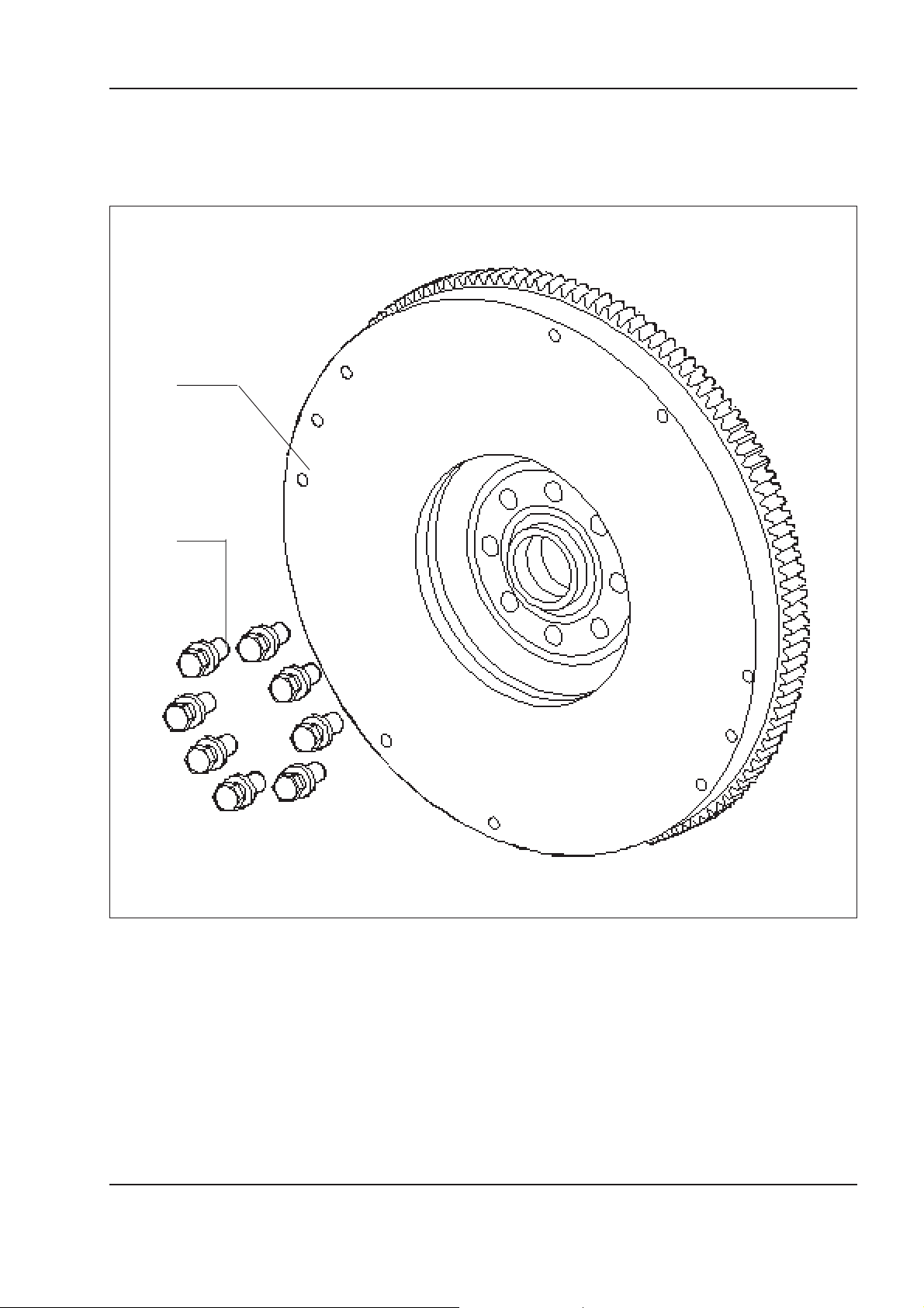
ENGINE
Copyright © New Holland
1 - 11W130/W130TC
Engine flywheel
Flywheel 1 does not require a set mounting on the
crankshaft, since it has no etching, mark or reference
holes for sensors or timing.
1
2
The same mounting distance of securing holes 2 allows a random installation.
W110R0105
Carefully read personal and machine SAFETY PRECAUTIONS (at the beginning of this manual)
Page 48

1 - 12 W130/W130TC
Copyright © New Holland
ENGINE
NOTES:
Carefully read personal and machine SAFETY PRECAUTIONS (at the beginning of this manual)
Page 49
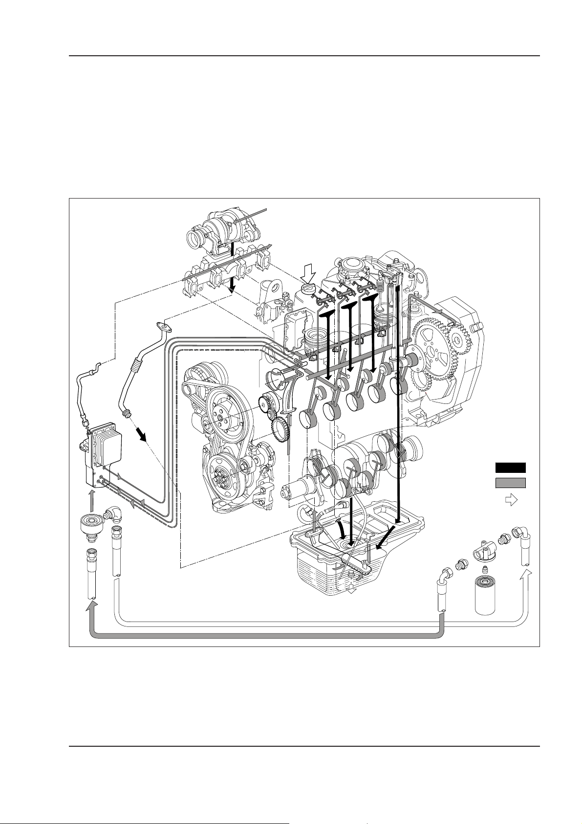
ENGINE
Copyright © New Holland
1.3 LUBRICATION
1 - 13W130/W130TC
The forced circulation lubrication is provided by the
following components:
• rotor oil pump, located in the lower side of the cyl-
inder block, driven by a straight teeth gear mounted
on the nose of the crankshaft;
• water/oil heat exchanger located on the cylinder
block, with connection for oil filter;
• oil pressure relief valve incorporated in the oil filter
connection;
• by-pass valve cutting off a clogged filter, incorporated with the oil filter connection;
• cartridge oil filter.
Oil natural return ducts
Oil pressure ducts
Oil filling
W110R0106
Carefully read personal and machine SAFETY PRECAUTIONS (at the beginning of this manual)
Page 50

1 - 14 W130/W130TC
Copyright © New Holland
ENGINE
NOTES:
Carefully read personal and machine SAFETY PRECAUTIONS (at the beginning of this manual)
Page 51
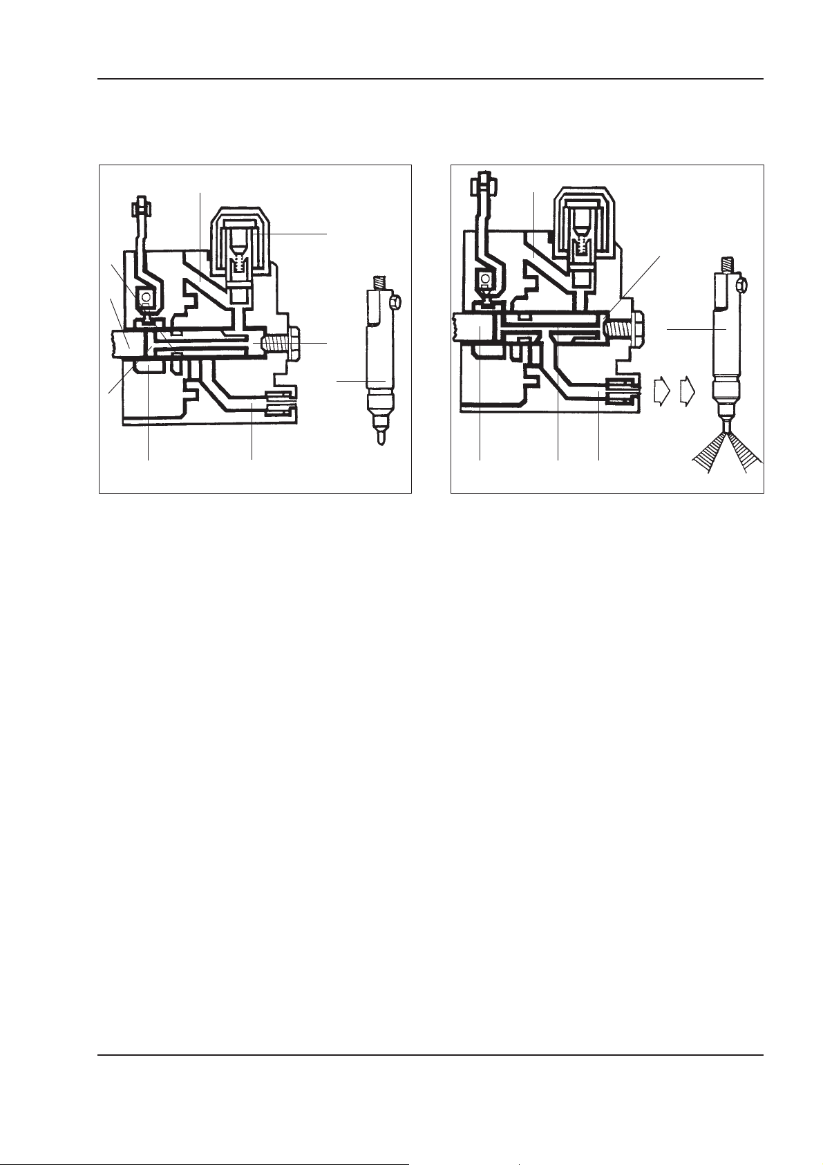
ENGINE
Copyright © New Holland
1.4 OPERATION DESCRIPTION FUEL SYSTEM
Supply phase Delivery phase
1 - 15W130/W130TC
1
2
3
6
4
9
7
85
1. Fuel inlet duct - 2. Solenoid valve - 3. Axial groove -
4. Compression chamber - 5. Duct between pumping ele-
ment and injectors - 6. Distribution piston - 7. Delivery cutoff hole - 8. Sliding element - 9. Injector.
W110R0107
1
2
6
534
1. Fuel inlet duct - 2. Compression chamber - 3. Distribu-
tion piston inner duct - 4. Fuel duct between pumping
element and injectors - 5. Distribution piston - 6. Injector.
W110R0108
Distribution piston (6) is at B.D.C. and sliding element
(8) closes delivery cut-off hole (7).
The fuel is forwarded to compression chamber (4)
through supply duct (1) kept open by solenoid valve
(2).
Carefully read personal and machine SAFETY PRECAUTIONS (at the beginning of this manual)
Page 52
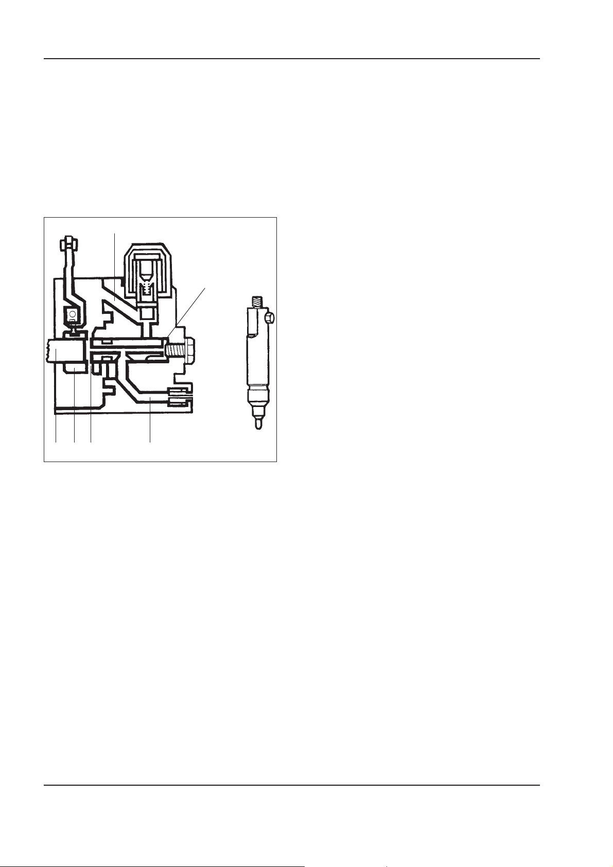
1 - 16 W130/W130TC
Copyright © New Holland
ENGINE
Distributor piston (5) under the defect of the rotation
of the cam disc, moves toward the T.D.C. and at the
same time, rotates on its own axis. The combination
of the two movements determines the shutting-off of
fuel inlet duct (q) and at the same time, the compression oof fuel in chamber (2). Inner duct (5) of the distributor piston is connected to duct (4) providing the
delivery to injectors (6).
End of delivery phase
1
2
654 3
1. Fuel inlet duct - 2. Compression chamber - 3. Delivery
duct - 4. End of delivery phase - 5. Sliding element - 6.
Distributor piston.
W110R0109
Distributor piston (6) when moving toward the T.D.C.
connects the high pressure inner chamber through duct
(1) providing a pressure equilibrium between the inner
chamber of the distributor piston, the delivery piping
to the injectors and the inside of the pump body.
Since this pressure is lower the value activating the
injector, the delivery ends.
Carefully read personal and machine SAFETY PRECAUTIONS (at the beginning of this manual)
Page 53
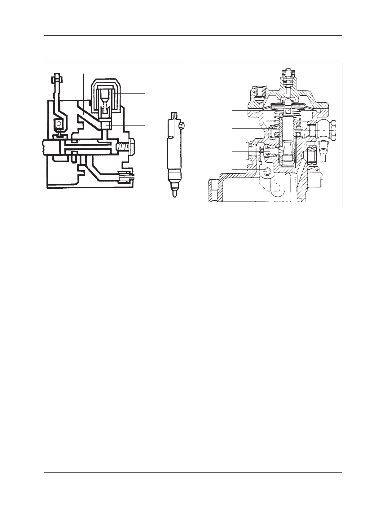
ENGINE
Copyright © New Holland
1 - 17W130/W130TC
Engine cut-off
1
4
3
2
5
1. Fuel inlet duct - 2. Mobile plug - 3. Spring - 4. Solenoid
valve - 5. Compression chamber.
L.D.A. device (delivery adjustment as a function of
the load)
1
2
3
4
5
6
7
8
W110R0111W110R0110
Operation of the L.D.A. device
The engine cut-off is provided by the cutting-off of the
starter contact. The electric power actuating solenoid
valve (4) is cut-off. The solenoid valve, under the effect of spring (3) pushes mobile plug (2) to stroke end
determining the closing of fuel inlet duct (1).
The L.D.A. device has the purpose of changing the
fuel delivery as a ratio of the air pressure monitored in
the intake manifold.
This air pressure actuates membrane (1) fitted on governor pin (4). In the lower side of governor pin (4) a
taper seat (5) is made on which sensor pin (6) slides.
The axial movement of governor pin (4) moves sen-
sor pin (6) that in turn actuates cut-off lever (7). The
cut-off lever turns on its axis (8) and actuates the
control plates so that the fuel deliveries are adjusted
to the quantity of air introduced into the cylinders.
Carefully read personal and machine SAFETY PRECAUTIONS (at the beginning of this manual)
Page 54
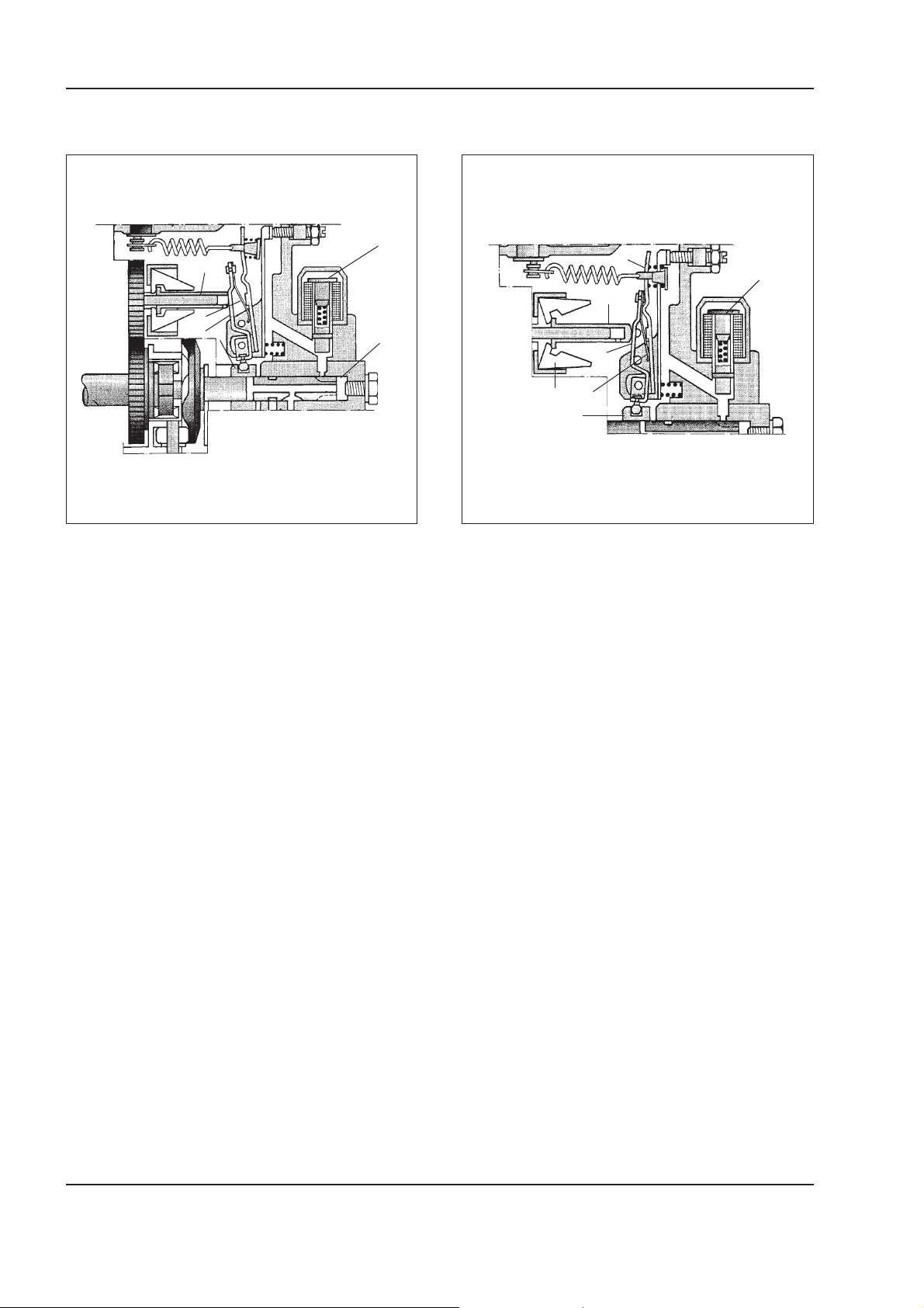
1 - 18 W130/W130TC
Copyright © New Holland
ENGINE
Starting
6
5
2
1
4
1. Starting lever - 2. Leaf spring - 4. Sliding element - 5.
Governor sleeve - 6. Solenoid valve - 7. Compression
chamber.
7
W110R0112
Starting device disengaged
3
6
5
1
2
7
4
W110R0113
1. Starter lever -2. Leaf spring - 3. Tension lever - 4. Sliding
element - 5. Governor sleeve - 6. Solenoid valve -
7. Masses.
After energising solenoid valve (6) fuel enters compression chamber (7). Under these conditions, governor sleeve (5) has the masses closed, thus leaf spring
(2) moves lever (1) and sliding element (4) into supplement position.
Thus the entire stroke of the pumping element is used
as delivery for the injection.
Once the engine is started, governor sleeve (5) under
the effect of the centrifugal force caused by the expansion of masses (7) starts moving axially, pushing
starter lever (1) against tension lever (3) thus presses
leaf spring (2).
Under these conditions, sliding element (6) moves
determining minimum delivery.
Carefully read personal and machine SAFETY PRECAUTIONS (at the beginning of this manual)
Page 55
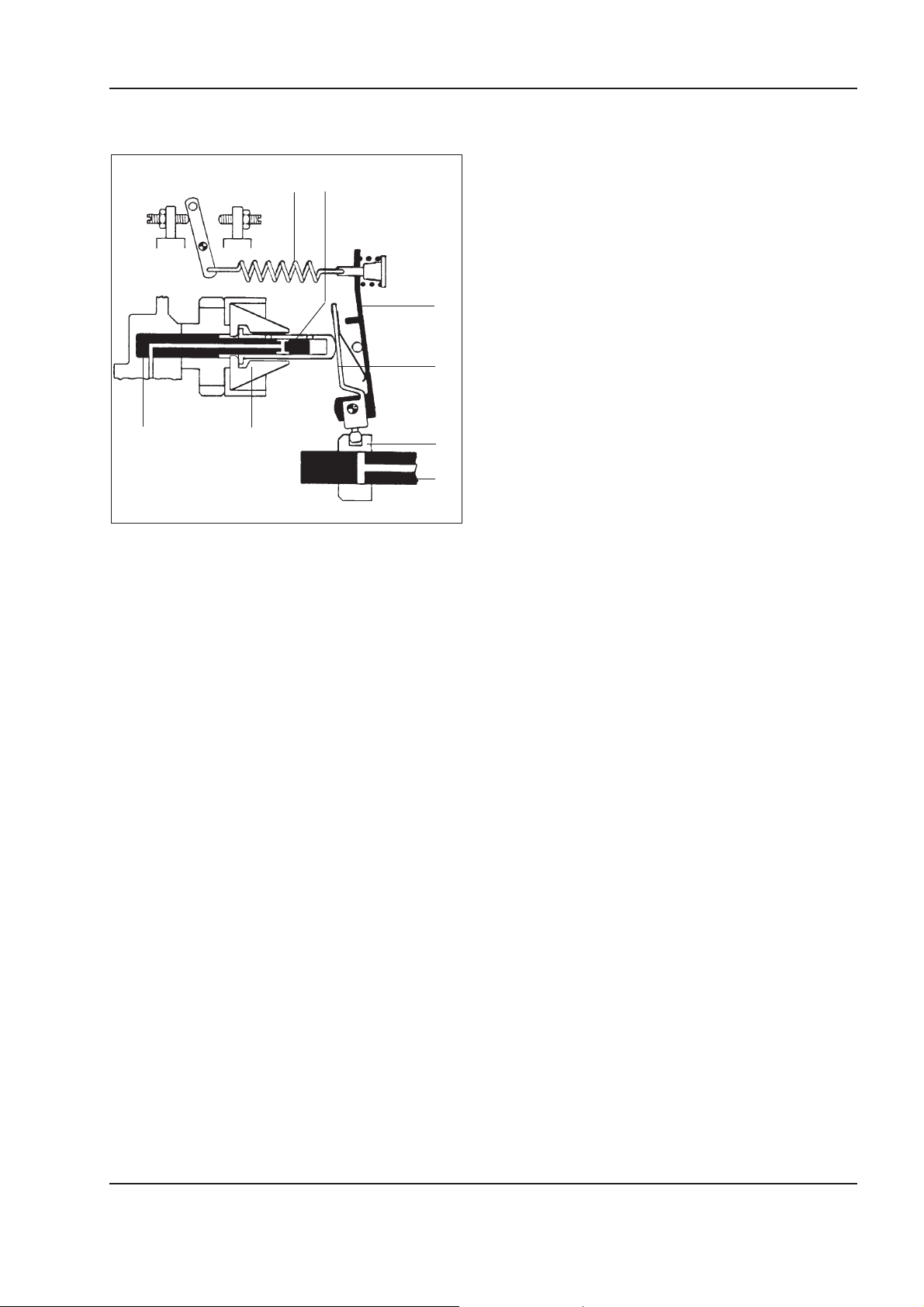
Beginning of delivery depending upon the load
Copyright © New Holland
(L.F.B.)
21
ENGINE
3
4
1 - 19W130/W130TC
87
5
6
W110R0114
Structure of the governor group with correction
of the beginning of delivery depending upon the
load
1. Governor spring - 2. Governor sleeve - 3. Tension lever
- 4. Starter lever - 5. Sliding element - 6. Distributor piston
- 7. Regulator shaft - 8. Centrifugal masses.
Description
The correction of the beginning of the delivery as a
function of the load (LFB) provides a "smoother" (less
noisy) operation of the engine.
The arrangement of the LFB device is obtained modifying:
• The governor sleeve has a hole supplementary to
the "anti lunging" hole.
• The governor support shaft with one longitudinal
hole and two cross-way holes.
• The body pump with one hole, closed from the outside by a ball communicating with the supply chamber.
Carefully read personal and machine SAFETY PRECAUTIONS (at the beginning of this manual)
Page 56
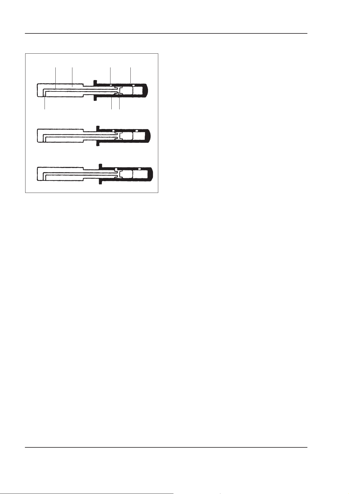
1 - 20 W130/W130TC
Copyright © New Holland
ENGINE
Position of the governor sleeve in the LFB
12 3 4
a
5
67
b
c
W110R0115
a. Sleeve in rest condition - b. Moving sleeve - c. Sleeve
under correction condition, drop of internal pressure - 1.
Longitudinal hole in the governor support shaft - 2. Governor shaft - 3. Governor sleeve cross-way hole - 4. Governor sleeve - 5. Governor shaft cross-way hole - 6. Edge
of governor shaft - 7. Governor shaft cross-way hole.
Operation
Notwithstanding the position of the outer throttle lever, when, under the increase of the rpm the governor
masses due to the centrifugal force, move governor
sleeve (4) a reduction in the delivery of fuel is determined. To provide a smoother operation of the engine
diminishing delivery a reduction of the advance must
correspond. Since in a rotary pump the advance device is hydraulically controlled, to reduce it a transfer
pressure decrement is required: this is provided by
the LFB device.
When governor sleeve (4) sliding on governor support
shaft (2) connects hole (3) with groove (6) and hole
(7) a portion of the fuel under pressure is discharged
through duct (1 and 5) in the supply chamber, causing
a drop of the transfer pressure inside the pump, thus
decreasing the advance.
Carefully read personal and machine SAFETY PRECAUTIONS (at the beginning of this manual)
Page 57
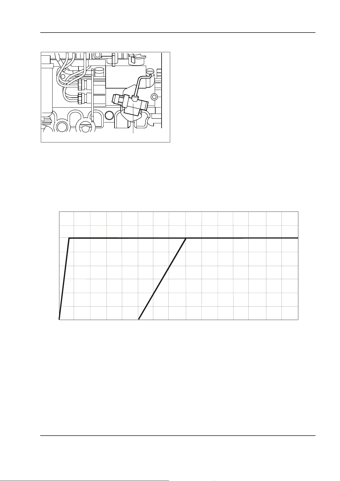
ENGINE
Copyright © New Holland
Cold injection automatic advance device (KKSB)
1
W110R0116
1. KKSB bulb.
The KKSB device has the function of setting an appropriate injection advance on a cold engine.
1 - 21W130/W130TC
8
6
Starting with KKSB
4
Advance degrees
2
0
0 500 1000 1500
Starting without KKSB
RPM
Carefully read personal and machine SAFETY PRECAUTIONS (at the beginning of this manual)
Page 58
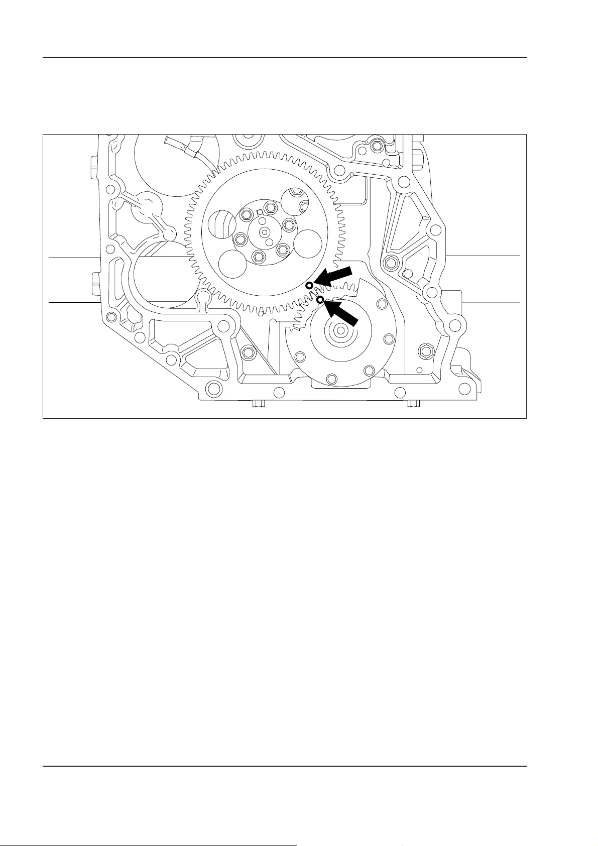
1 - 22 W130/W130TC
Copyright © New Holland
ENGINE
Timing
The timing drive is provided by a straight teeth gear
mounted on the rear tip of the crankshaft driving the
gear mounted on the camshaft.
The timing is provided by coinciding marks (⇐) etched
on them.
W110R0117
Carefully read personal and machine SAFETY PRECAUTIONS (at the beginning of this manual)
Page 59
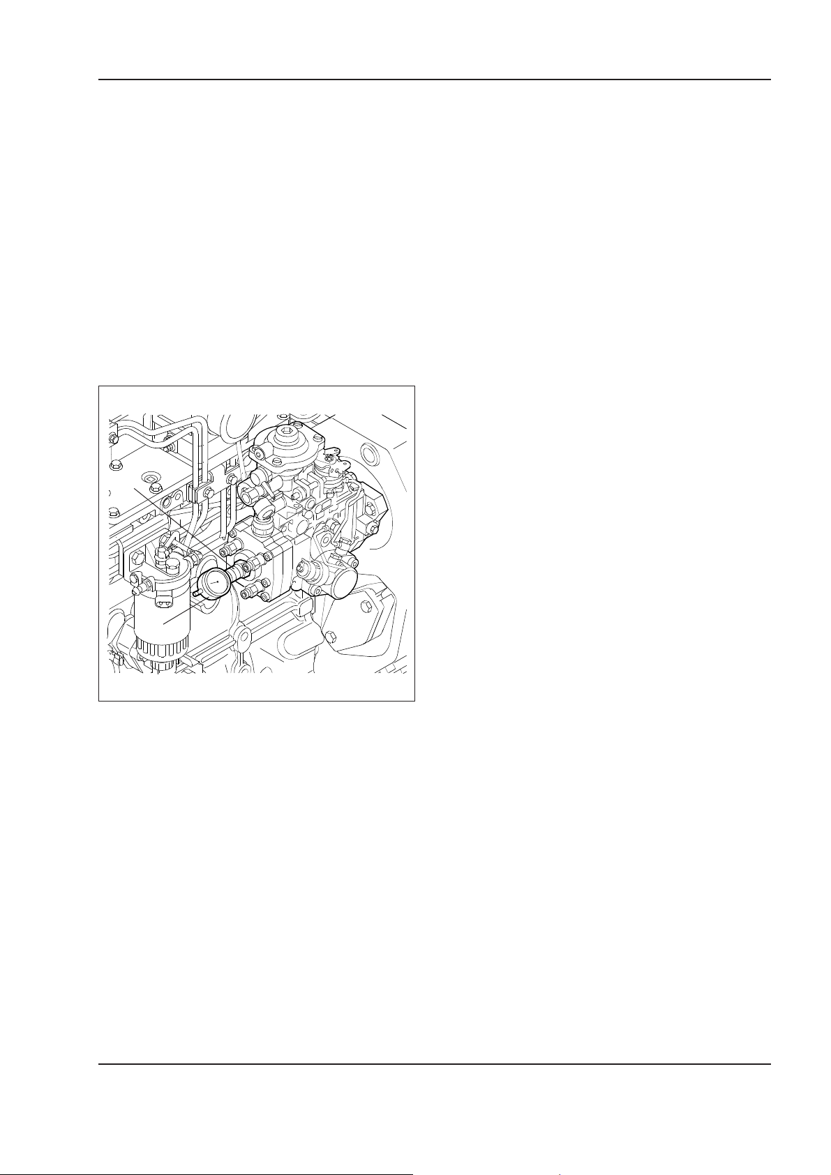
Timing of the injection pump
Copyright © New Holland
To set the timing of the crankshaft with the camshaft,
move the first piston to T.D.C. This condition is obtained by turning the crankshaft until the pin on the
gear housing near the injection pump enters the relevant seat of the camshaft gear.
When a spare injection pump is supplied as spare
part, it is already pre-set, thus it is sufficient to install
it on the timing gear, mount it on the gear housing and
remove appropriately the seal ensuring the pre-setting of the pump by locking its shaft.
To check the correct timing, place a dial gauge
380000228 (2) and adapter 99395100 (1) on the pump,
as indicated in the figure.
ENGINE
1 - 23W130/W130TC
1
2
W110R0118
Turn appropriately the crankshaft to eliminate the gear
backlash and return the engine under the conditions
of first piston at T.D.C.
The dial gauge reads the desired pre-load value (see
Repair Manual). If the prescribed value is not obtained,
loosen the screws securing the pump to the gear housing and slide the pump body on the slots until the
correct pre-load value is obtained.
When the injection pump is overhauled. it is not preset, thus it is necessary to install it when the first
piston is at T.D.C. and proceed with the setting of the
pre-load value, installing the dial gauge and adapter
sliding it on the slots and secure it to the gear housing. Proceed with the check as described here above.
Carefully read personal and machine SAFETY PRECAUTIONS (at the beginning of this manual)
Page 60
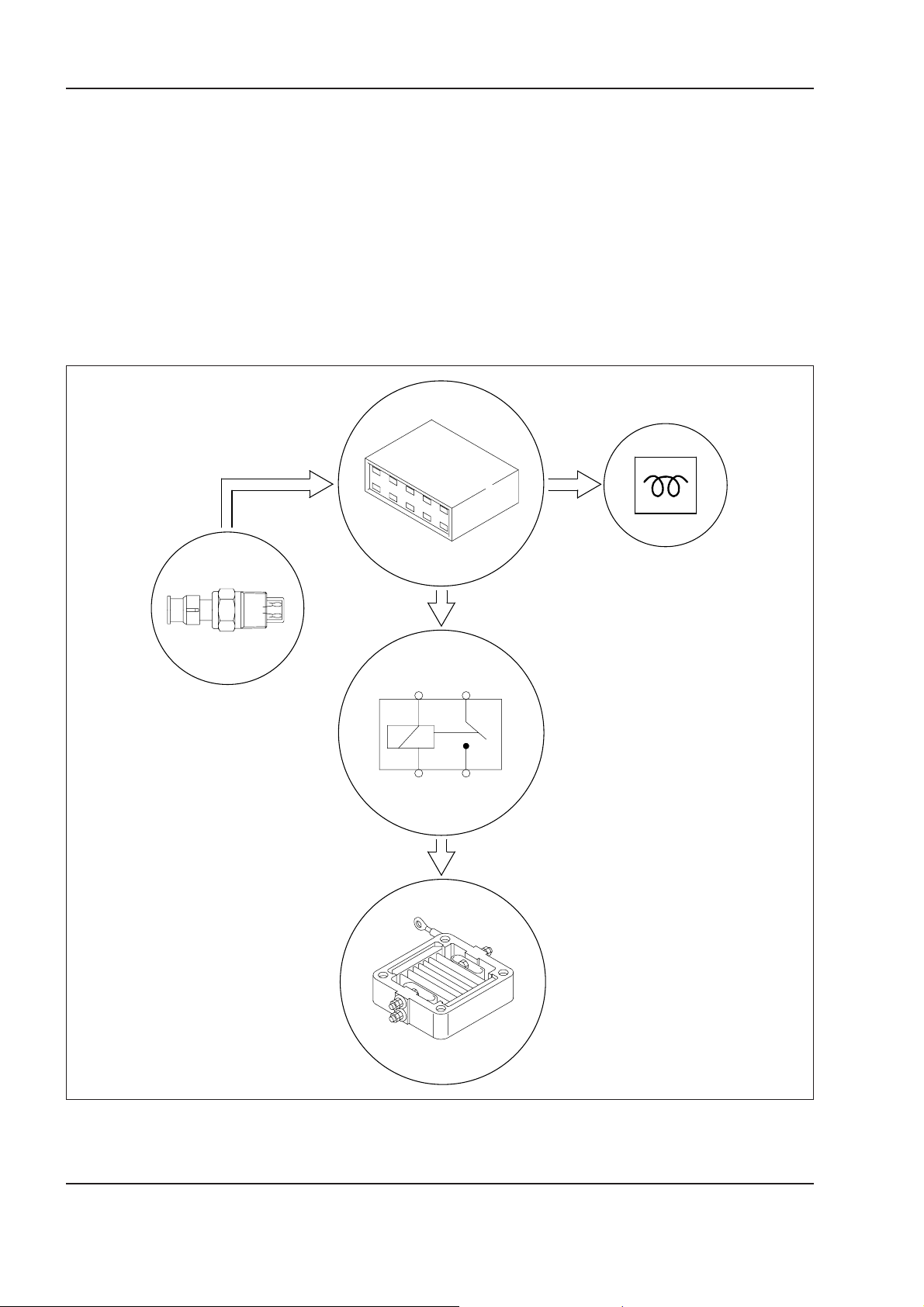
1 - 24 W130/W130TC
Copyright © New Holland
ENGINE
Electrical components
• Pre-post heater kit
• KKSB water temperature sensor on injection pump
• Oil pressure sensors piloting the oil pressure indicator light on instrument dashboard
• Thermal bulb for KKSB on injection pump
(*) Controller, engine coolant temperature sensor,
heater.
Principle diagram
2
Pre-post heater controller
Controller 1 establishes the time of intervention of the
heater (pre-post heating) as a function of the signal
received from engine coolant temperature sensor 2.
1
5
4
3
W110R0119
1. Pre-post heating controller - 2. Coolant temperature sensor - 3. Heater solenoid switch - 4. Heater - 5. Preheating
dashboard indicator light.
Carefully read personal and machine SAFETY PRECAUTIONS (at the beginning of this manual)
Page 61

REMEDIES
Copyright © New Holland
Check, recharge the batteries and replace them if
ENGINE
1.5 TROUBLESHOOTING GUIDE
required.
Clean, inspect, tighten fixtures and replace exces-
sively corroded terminals and nuts, if required.
Have a correct timing of the injection pump on the
engine.
Disconnect pipes, injection pump and clean them
accurately and if required, clean and dry the fuel
tank.
Refill.
Check fuel pump and replace it, if required.
1 - 25W130/W130TC
Check pipes, connections, fuel pump, filters and
injection pump to make sure they are free from air
then bleed the system.
Repair or replace the starter motor.
Check or replace cold starter.
POSSIBLE CAUSES
or loosen.
1. Partially discharged batteries.
TROUBLES
The engine fails to start
2. Connections to the battery terminals corroded
pipes.
3. Wrong timing of injection pump on engine.
4. Accumulation of sediments and water in the fuel
5. Tank out of fuel.
6. No supply to injection pump.
7. Presence of air in the fuel system.
8. Starter motor damaged.
9. Cold starting device inefficient.
Carefully read personal and machine SAFETY PRECAUTIONS (at the beginning of this manual)
Page 62

1 - 26 W130/W130TC
Copyright © New Holland
ENGINE
REMEDIES
Adjust low idle.
Re-calibrate on bench.
Disconnect pipes, injection pump and clean them
accurately and if required, clean and dry the fuel
tank.
Replace the filter cartridges.
Adjust valve clearance.
Replace valves.
Check pipes, connections, fuel pump, filters and
injection pump to make sure they are free from air
then bleed the system.
Replace damaged parts.
POSSIBLE CAUSES
1. Low idle too low.
2. Irregular deliveries of injection pump.
3. Accumulation of sediments and water in fuel
TROUBLES
The engine dies
pipes.
4. Fuel filters clogged.
5. Abnormal valve clearance.
6. Valves burnt or cracked.
7. Presence of air in the fuel system.
8. Injection pump controls damaged.
Carefully read personal and machine SAFETY PRECAUTIONS (at the beginning of this manual)
Page 63

REMEDIES
Copyright © New Holland
Overhaul the injection pump and replace it, if re-
quired.
Replace the thermostat.
Eliminate any scaling by flushing. Check and re-
pair any leakage from the tubes.
Flush accurately.
Check and adjust the belt.
ENGINE
Top-up level in the expansion tank using prescribed
liquid.
Check and re-set timing.
Calibrate injection pump on bench complying with
the calibration tables.
Clean the group and, if required, replace filtering
the element.
1 - 27W130/W130TC
POSSIBLE CAUSES
1. Cooling centrifugal pump inefficient.
2. Thermostat inefficient.
TROUBLES
The engine overheats
cylinder block.
3. Radiator partially inefficient.
4. Scaling in the coolant ducts in cylinder head and
fan belt.
5. Insufficient tension of centrifugal pump drive and
6. Coolant insufficient (quantity).
and defect.
7. Wrong timing.
8. Injection pump out of calibration both in excess
9. Air cleaner clogged.
Carefully read personal and machine SAFETY PRECAUTIONS (at the beginning of this manual)
Page 64

1 - 28 W130/W130TC
Copyright © New Holland
ENGINE
REMEDIES
Have the injection pump correctly timed on the en-
gine.
Overhaul the injection pump and calibrate it on test
bench complying with the relevant calibration table.
Overhaul the injection pump and calibrate it on test
bench complying with the relevant calibration table.
Overhaul the injection pump and calibrate it on test
bench complying with the relevant calibration table.
Overhaul the injection pump and calibrate it on test
bench complying with the relevant calibration table.
Clean, overhaul and calibrate correctly the injectors.
Check pipes, connections, fuel pump, filters and in-
jection pump to make sure they are free from air
then bleed the system.
Replace fuel pump.
Adjust valve clearance.
Check compression and overhaul the engine, if re-
quired.
Clean the group and replace filtering element, if
rquired.
Adjust the length of the linkage.
Adjust high idle screw.
POSSIBLE CAUSES
damaged.
1. Wrong timing of injection pump on engine.
2. Advance automatic variator on injection pump
TROUBLES
The engine is under powered and
operates irregularly
pipes.
3. Distributor pumping element worn.
4. Injection pump deliveries irregular.
5. Governor damaged at all speeds.
6. Injectors partially clogged or damaged.
7. Accumulation of sediments or water in fuel
8. Fuel pump damaged.
9. Valve clearance abnormal.
tion pump to be adjusted.
10. Compression in cylinders insufficient.
11. Air cleaner clogged.
12. Length of linkage between throttle and injec-
justment.
13. Injection pump with high idle screw out of ad-
Carefully read personal and machine SAFETY PRECAUTIONS (at the beginning of this manual)
Page 65

REMEDIES
Copyright © New Holland
Clean, overhaul and correctly calibrate the injec-
ENGINE
tors.
Clean the pipes and replace those with consider-
able dents. Clean injection pump, if required.
Have the injection pump on the engine correctly
timed.
Regrind the crankshaft journals, install oversized
bearings and thrust bearings.
Check the alignment and balance of the crankshaft
and replace it, if required.
Replace loosen screws and tighten all of them to
the prescribed torque + angle.
Straighten the con-rods, check the parallelism of
the centre lines and replace them, if required.
Regrind the cylinder sleeves and install oversized
pistons.
Replace the piston pin with an oversized one, re-
bore the seats on the piston and the conrod bushes.
Replace the bushes with new ones.
Check that there are no broken springs, there is no
excessive play between stems and guides, tap-
pets and seats. Adjust valve clearance.
1 - 29W130/W130TC
POSSIBLE CAUSES
1. Injectors partially clogged or damaged.
2. Accumulation of sediments in fuel pipes.
TROUBLES
The engine has abnormal knockings
play of one or more crankshaft or conrod jour-
nal bearings or thrust bearings.
3. Wrong timing of injection pump on engine.
4. Engine crankshaft knocking due to excessive
5. Crankshaft out of balance.
6. Flywheel securing screws loosen.
7. Conrod axes out of line.
tween piston seat and conrod bushing. Bush-
ing floating in conrod seat.
8. Pistons knocking due to abnormal wear.
9. Piston pins noisy due to excessive play be-
10. Rattling due to noisy timing.
Carefully read personal and machine SAFETY PRECAUTIONS (at the beginning of this manual)
Page 66

1 - 30 W130/W130TC
Copyright © New Holland
ENGINE
REMEDIES
Calibrate the injection pump on bench complying
with the calibration table.
Have the injection pump correctly timed on the
engine and check the automatic advance variator.
Have the injection pump correctly timed on the
engine.
Clean, overhaul and correctly calibrate the injec-
tors. replace them, if required.
Clean the group and replace the filtering element, if
required.
Replace damaged parts and overhaul the engine,
if required.
Check the conditions of the pipes.
POSSIBLE CAUSES
the automatic advance variator is damaged.
1. Maximum delivery of injection pump excessive.
2. The injection pump is excessively delayed or
TROUBLES
The engine smokes abnormally:
black or dark grey smoke
calibration.
3. The injection pump is excessively advanced.
4. Injectors partially and7or fully clogged or out of
5. Air cleaner clogged.
- Sticky piston rings;
- Worn cylinder sleeves;
- Valves deteriorated or out of adjustment.
6. Loss of compression on engine due to:
7. Injection pumps damaged.
Carefully read personal and machine SAFETY PRECAUTIONS (at the beginning of this manual)
Page 67

REMEDIES
Copyright © New Holland
Have the injection pump correctly timed on the
ENGINE
engine and check the automatic advance variator.
Clean, overhaul and correctly calibrate the injec-
tors. replace them, if required.
Replace damaged parts and overhaul the engine,
if required.
Overhaul cylinder head.
Replace the thermostat.
Replace the solenoid valve.
Overhaul injection pump and calibrate it on test
1 - 31W130/W130TC
bench complying with the relevant calibration ta-
ble.
POSSIBLE CAUSES
the automatic advance variator is damaged.
1. The injection pump is excessively delayed or
2. Injectors seized or defective.
TROUBLES
Blue, grey-blue or grey tending to white
smoke
sticky rings or wear of cylinder sleeves.
3. Passage of oil through piston rings caused by
due to wear of guides or valve stems.
4. Passage of oil through the intake valve guides
ture (thermostat damaged)
5. The engine does not reach operation tempera-
1. Cut-off solenoid valve damaged.
2. Governor at all speeds damaged.
Engine does not cut-off
Carefully read personal and machine SAFETY PRECAUTIONS (at the beginning of this manual)
Page 68

1 - 32 W130/W130TC
Copyright © New Holland
ENGINE
NOTES:
Carefully read personal and machine SAFETY PRECAUTIONS (at the beginning of this manual)
Page 69
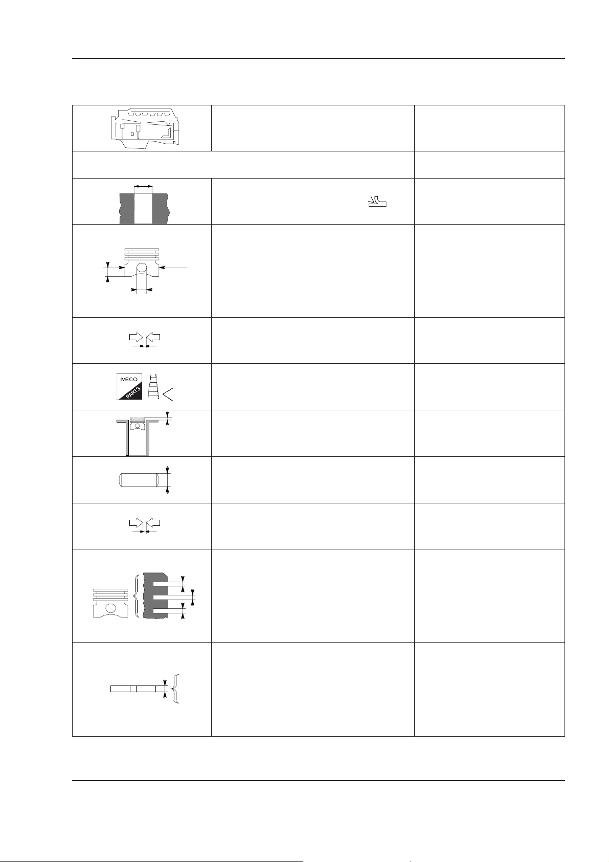
DATA - MOUNTING PLAYS
Copyright © New Holland
ENGINE
Type F4GE0484E
1 - 33W130/W130TC
CYLINDERS AND CRANKING COMPONENTS GROUP
Ø 1
Cylinder sleeves Ø 1 102.01 to 102.03
Pistons: supplied as spares
Ø 1
X
parts type
Position of measurement X 61
Outer diameter Ø 1 101.777 to 101.795
Ø 2
Pin seat Ø 2 40.006 to 40.012
Piston - cylinder sleeve 0.215 to 0.253
Diameter of pistons Ø 1 0.5
X
Position of pistons in cylinder block X 0.28 to 0.52
mm
Ø 3
S1
S2
S3
Piston pin Ø 3 39.9968 to 40.0032
Piston pin - pin seat 0.0028 to 0.0152
Type of piston
X1
Piston rings seat X2* 2.425 to 2.445
X2
X3
X1* 2.69
X3* 4.04 to 4.06
* measured on the 99 mm diameter
S1* 2.560 to 2.605
Piston rings S2* 2.310 to 2.340
S3* 3.075 to 4.000
* measured on the 99 mm diameter
Carefully read personal and machine SAFETY PRECAUTIONS (at the beginning of this manual)
Page 70
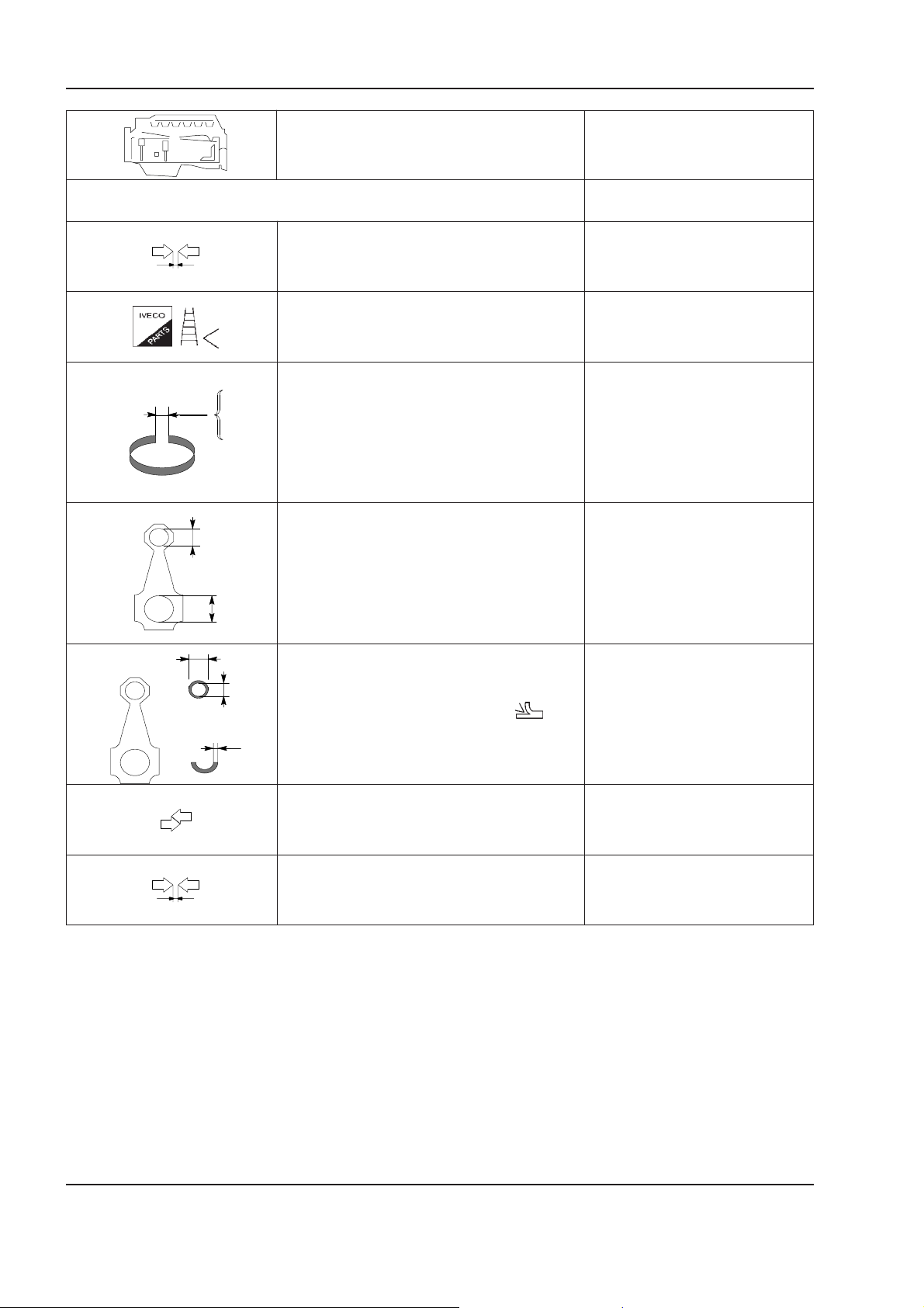
1 - 34 W130/W130TC
Copyright © New Holland
ENGINE
Type F4GE0484E
CYLINDERS AND CRANKING COMPONENTS GROUP
Piston rings - seats 2 0.085 to 0.135
Piston rings 0.5
X1
X2
X3
Ø 1
Gap and end of piston rings in the
cylinder sleeves:
Conrod small end bush seat Ø 1 42.987 to 43.013
Ø 2
Ø 4
Conrod large end bearing seat Ø 2 77.075 to 78.25
mm
1 0.245 to 0.265
3 0.040 to 0.985
X1 0.40 to 0.70
X2 0.25 to 0.55
X3 0.25 to 0.55
Ø 3
Diameter of conrod small end bush
Outer Ø 4 43.279 to 43.553
Inne r Ø 3 40.019 to 40.033
S
Conrod half bearings 1.955 to 1.968
Conrod small end bush - seat 0.266 to 0.566
Piston pin - bush 0.0158 to 0.0362
Carefully read personal and machine SAFETY PRECAUTIONS (at the beginning of this manual)
Page 71
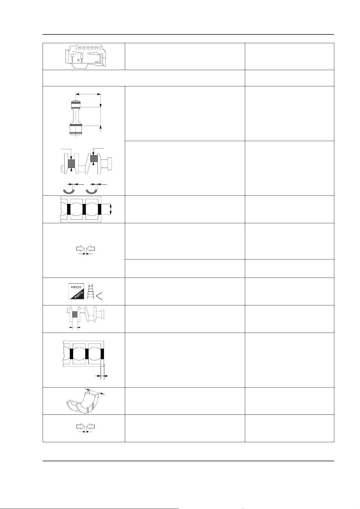
ENGINE
Copyright © New Holland
Type F4GE0484E
1 - 35W130/W130TC
CYLINDERS AND CRANKING COMPONENTS GROUP
X
Position of measurement X -
Maximum error on parallelism
of conrod axes = -
Ø 2Ø 1
Main journals Ø 1 82.99 to 83.01
Conrod journals Ø 2 68.987 to 69.013
Main journal half bearings S1* 2.456 to 2.464
S1 S2
Conrod half bearings S2* 1.955 to 1.968
* supplied as spare part
Main journal no.:
Ø 3
no. 1 - 5 Ø 3 87.982 to 88.008
no. 2-3-4 Ø 3 87.977 to 88.013
Half bearings - main journals:
no. 1-5 0.041 to 0.119
no. 2-3-4 0.041 to 0.103
mm
Half bearings - conrod journals 0.033 to 0.041
Main journal half bearings
+ 0.250; + 0.500
Conrod journals bearings
Thrust main journal X1 34.475 to 37.545
X1
Main journal for thrust bearing X2 25.98 to 26.48
X2
X3
Thrust half rings X3 37.28 to 37.38
Crankshaft thrust 0.068 to 0.41
Carefully read personal and machine SAFETY PRECAUTIONS (at the beginning of this manual)
Page 72
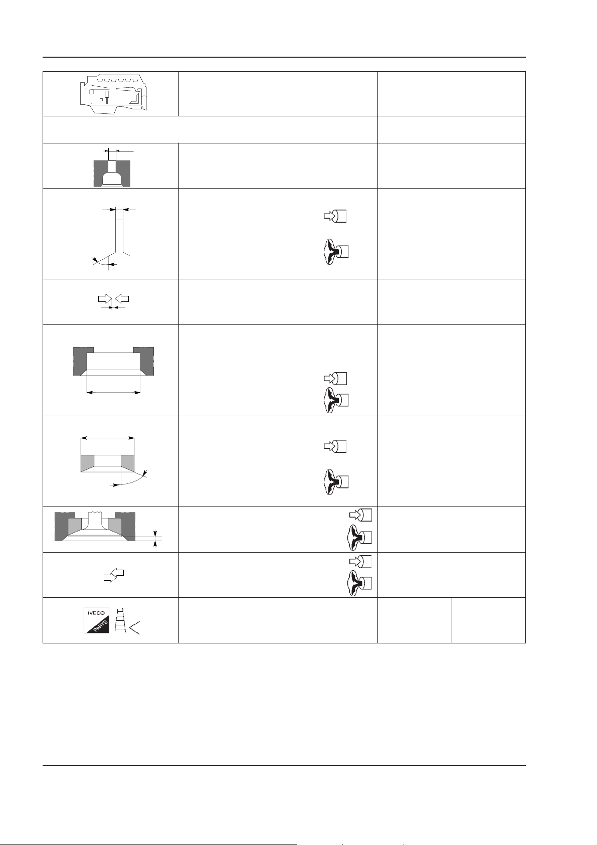
1 - 36 W130/W130TC
Copyright © New Holland
ENGINE
Type F4GE0484E
CYLINDER HEAD - TIMING
Ø 1
mm
Valve guide seat on cylinder head Ø 1 8.019 to 8.039
Ø 4
Valves:
Ø 4 7.96 to 7.98
α 60°
Ø 4 7.96 to 7.98
α
α 45°
Valve stem and relevant guide 0.052 to 0.092
Seat on cylinder head
for valve seat:
Ø 1 46.987 to 47.013
Ø 1
Ø 1 43.637 to 43.663
Ø 2
Valve seat outer diameter; angle of
valve seats on cylinder head: Ø 2 47.063 to 47.089
α 60°
α
Ø 2 43.713 to 43.739
α 45°
Recess X 0.356 to 1.102
X
X 0.104 to 0.84
Between valve seat 0.050 to 0.102
and head 0.050 to 0.102
Valve seats - -
Carefully read personal and machine SAFETY PRECAUTIONS (at the beginning of this manual)
Page 73
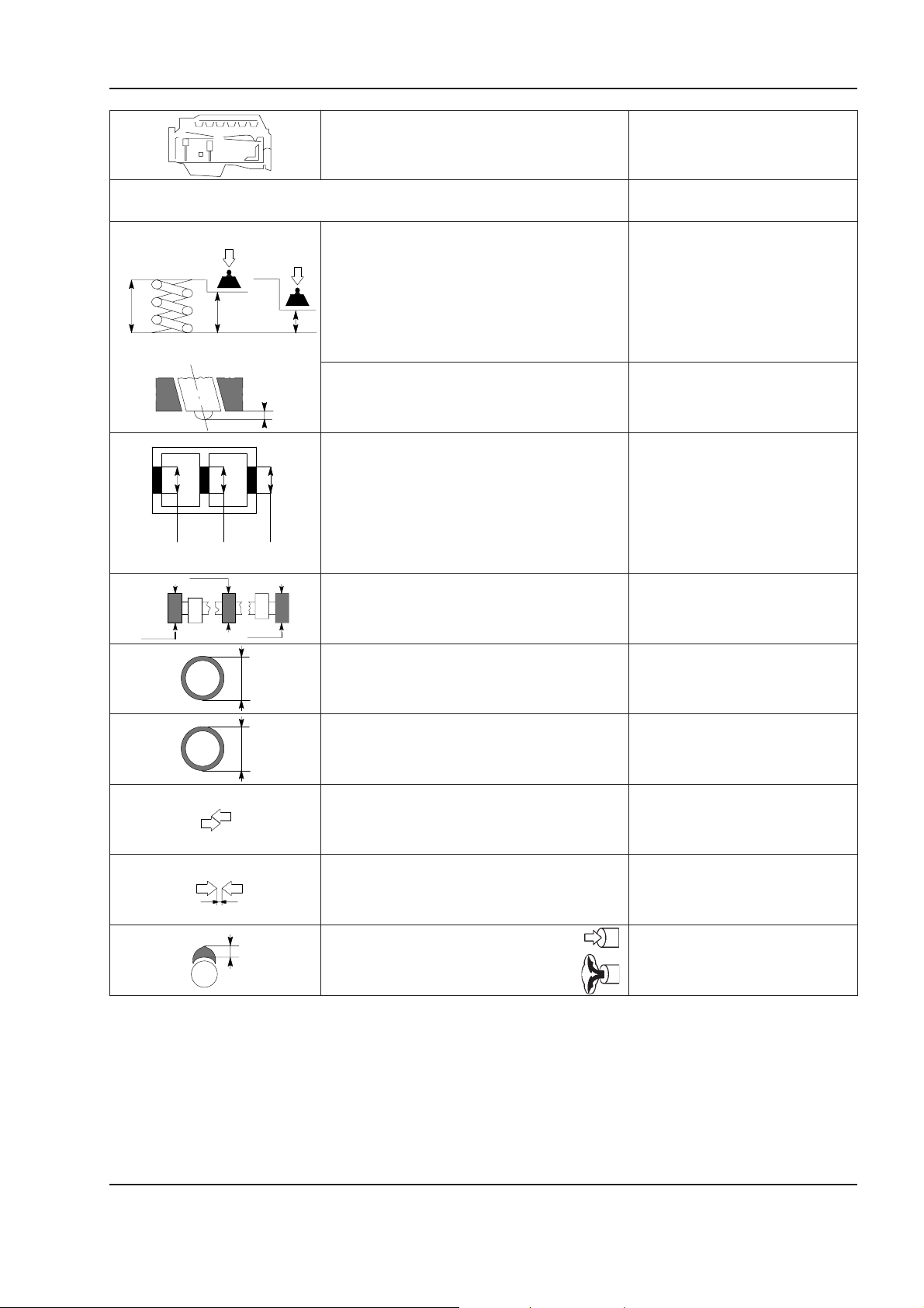
ENGINE
Copyright © New Holland
Type F4GE0484E
1 - 37W130/W130TC
CYLINDER HEAD - TIMING
mm
Height of valve spring:
free length H 63.5
H
H1
under a load of:
H2
329 H1 49.02
641 H2 38.2
Protrusion of injectors X not adjustable
X
Camshaft bushes
-
-
ØØØ
1 2 3 4 5
no. 1-5
Camshaft seats
no. 2-3-4
Camshaft support
journals:
Ø 3Ø 1
1 ⇒ 5 Ø 53.995 to 54.045
Ø
Ø
Camshaft bushes outer diameter Ø -
Bushes inner diameter Ø -
Bushes and seats in cylinder block -
Bushes and journal 0.038 to 0.162
H
Cam lifting:
-
-
Carefully read personal and machine SAFETY PRECAUTIONS (at the beginning of this manual)
Page 74
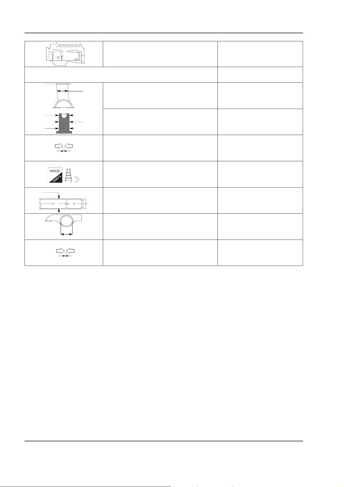
1 - 38 W130/W130TC
Copyright © New Holland
ENGINE
Type F4GE0484E
Ø 1
Ø 2
CYLINDER HEAD - TIMING
Seat of tappet plate
in cylinder block Ø 1 -
Outer diameter tappet plate:
Between tappets and seats 0.025 to 0.070
Tappets -
Rocker arm shaft Ø 1 18.963 to 18.975
Rocker arms Ø 2 19.000 to 19.026
mm
Ø 2 15.929 to 15.959
Ø 3 15.965 to 15.930
Between rocker arm and shaft 0.025 to 0.063
Carefully read personal and machine SAFETY PRECAUTIONS (at the beginning of this manual)
Page 75
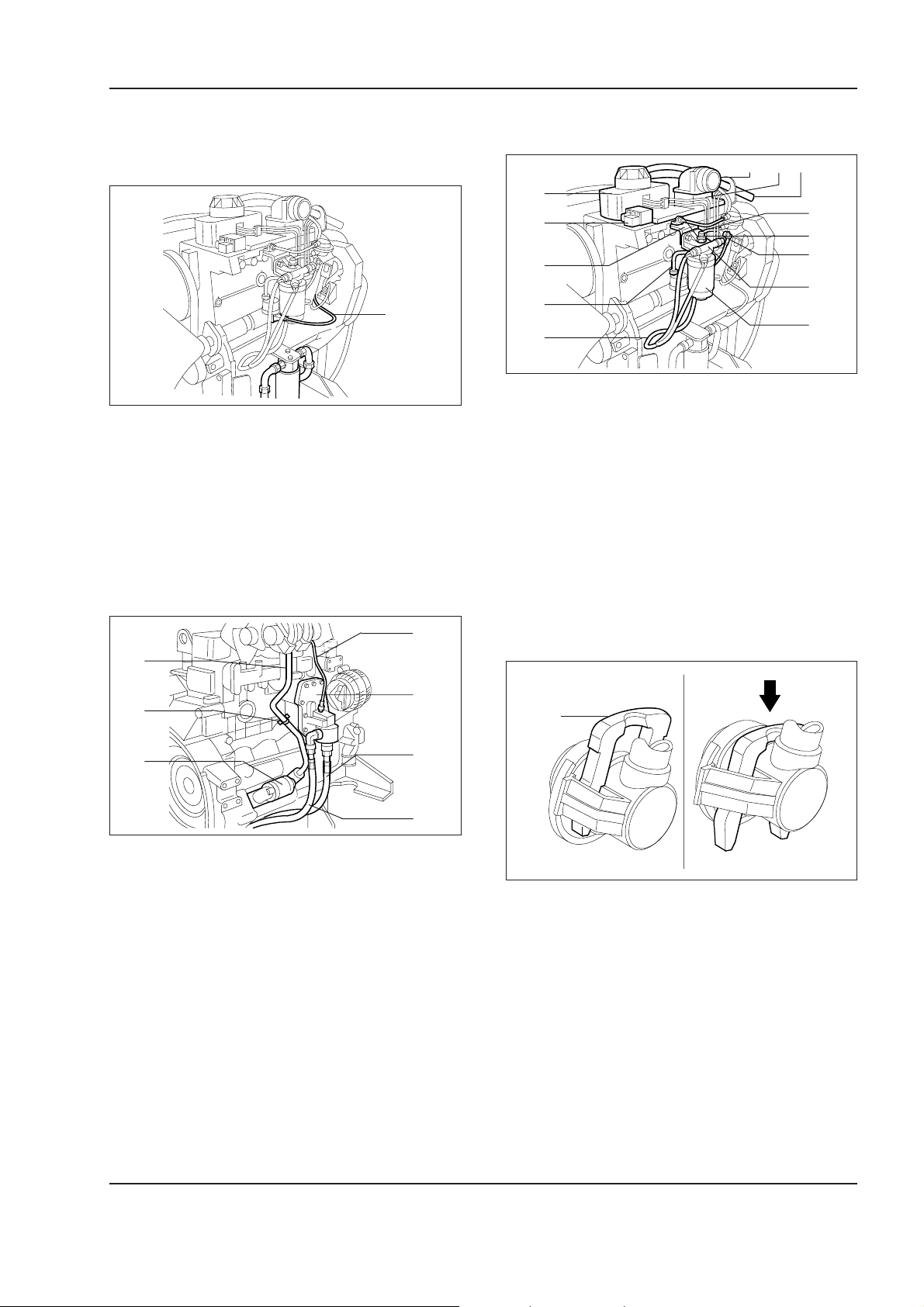
ENGINE
Copyright © New Holland
1.6 ENGINE OVERHAUL ON BENCH
1 - 39W130/W130TC
Disassembly of engine
1
W110R0120
Drain the engine oil by removing the sump plug and
the engine oil filler neck from the cylinder head cover.
Remove the fan group from the fan pulley.
In order to install the stand mounting bracket 75301886
to the engine cylinder block, it is necessary to operate on the left side of the engine as follows:
- remove electric harness (1).
3
2
1
4
5
13
12
6
11
10
7
9
8
W110R0122
- remove engine oil fume recovery pipe from blowby (1);
- remove rocker arm cover (4);
- remove electric harness (8);
- remove fuel filter (9);
- remove intake manifold (3);
- remove heater (5);
- remove LDA system (13);
- remove quick release coupling pipes (7), (10), (11)
and (13);
- remove fuel filter support (6).
7
1
6
2
3
5
4
W110R0121
To install bracket 75301886 on the right side, remove:
- starter motor (3);
- securing bracket (2) of oil return pipe (1);
- the oil return piping (1) relative to the turbine;
- remove oil pipes (4) and (5) from heater exchanger
(6).
Install the engine on rotary stand 75296375.
- disconnect turbine lube oil delivery (7);
AB
1
W110R0123
Move fork (1) as indicated in the figure (item A) and
remove the connection. To prevent deformations when
the connection is removed, return fork (1) into the locking position (item B).
Carefully read personal and machine SAFETY PRECAUTIONS (at the beginning of this manual)
Page 76
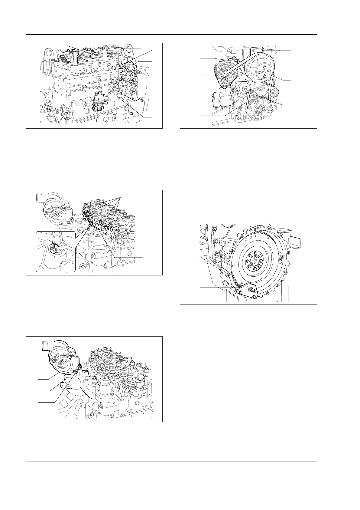
1 - 40 W130/W130TC
Copyright © New Holland
ENGINE
1
2
3
6
5
4
W110R0124 W110R0127
- Disconnect supply pipes (5) of injectors (5) from
injection pump (6). Remove pipe groups securing
brackets on the cylinder head (1) (2) and (3).
- Remove fuel pump (4).
1
9
1
2
4
3
7
6
- Remove belt tensioner (4).
- Remove auxiliary organs belt (6) moving bracket
(1) securing the alternator.
- Remove alternator (2) water pump (5) fan pulley (8)
and guide pulleys (7).
- Remove pulley support (9).
- Remove engine cooling system connection (3) from
the cylinder block.
3
2
4
W110R0125
- Remove injector supply pump group (1) from the
injectors.
- Remove fuel return pipe (2) from the injectors removing screws (4) and gasket (3).
1
2
3
1
W110R0128
Install tool (1) 380000144 on the flywheel housing to
block the flywheel.
- Remove screws (3) and remove turbine (2).
- Remove exhaust manifold (2).
Carefully read personal and machine SAFETY PRECAUTIONS (at the beginning of this manual)
W110R0126
Page 77
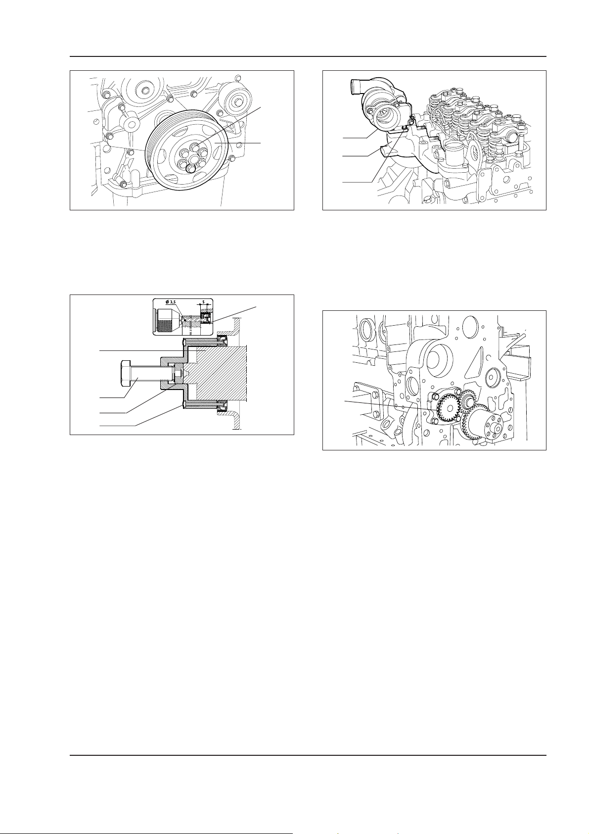
1
Copyright © New Holland
ENGINE
1 - 41W130/W130TC
2
W110R0129
Remove securing screws (1) from pulley (2).
Replacing the seal
1
2
3
4
5
W110R0130
Install tool (4) 380000665 on nose (2) of the crankshaft.
Drill inner seal ring (1) with a drill (3.5 mm diam.)
through the holes of tool 380000665 (4) for a depth of
5 mm.
Install tool 380000665 (4) on ring (1) tightening the 6
screws (5) provided.
Pullout ring (1) tightening screw (3).
1
2
3
W110R0131
Install the appropriate puller (3) of tool 380000669 to
outer seal (2) as described in the figure and pull it out
from front cover (1) using lever (4).
Remove the front cover.
1
W110R0132
Remove oil gear pump (1).
Important –
Oil pump (1) cannot be overhauled.
Carefully read personal and machine SAFETY PRECAUTIONS (at the beginning of this manual)
Page 78
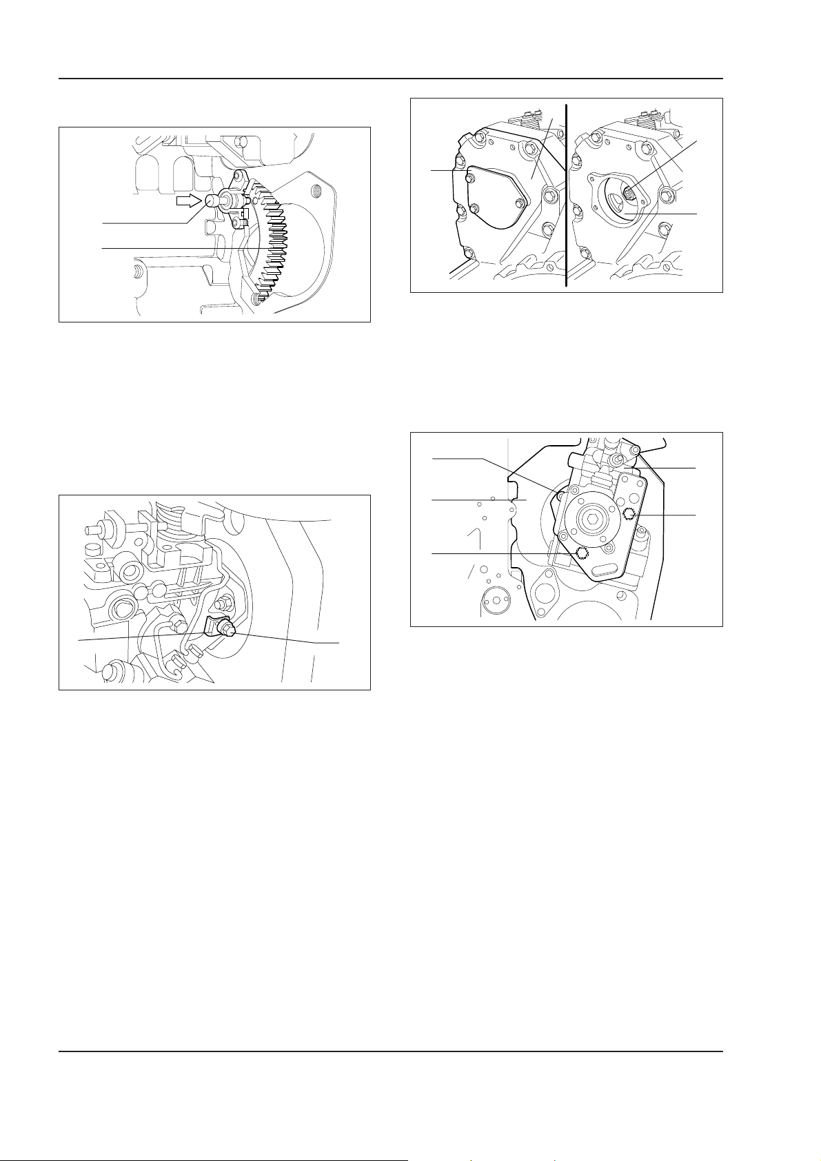
1 - 42 W130/W130TC
Copyright © New Holland
ENGINE
Removal of injection pump
1
2
W110R0133
Prior to removing the injection pump and the flywheel
locking tool.
Turn the crankshaft until the 1st cylinder is at T.D.C.
The condition of cylinder no. 1 in T.D.C. is obtained
when pushing pin (1) indicated by the arrow enters its
seat located on camshaft drive gear (2).
BA
2
3
1
4
W110R0135
- Remove cover (1) from gear housing (2).
- Lock the engine flywheel.
- Remove nut (3) securing the injection pump drive
gear (4).
2
1
3
5
1
2
W110R0134
To pre-set correctly the injection pump, loosen screw
(2) and remove (1) "L" spacer.
Retighten screw (2) to contact.
Important –
Keep the "L" spacer appropriately with
the pump body.
4
W110R0136
Remove the three nuts (2) (4) (5) securing injection
pump (1) to flywheel housing (3) and pull-it out from
its seat using tool 75295944.
Carefully read personal and machine SAFETY PRECAUTIONS (at the beginning of this manual)
Page 79
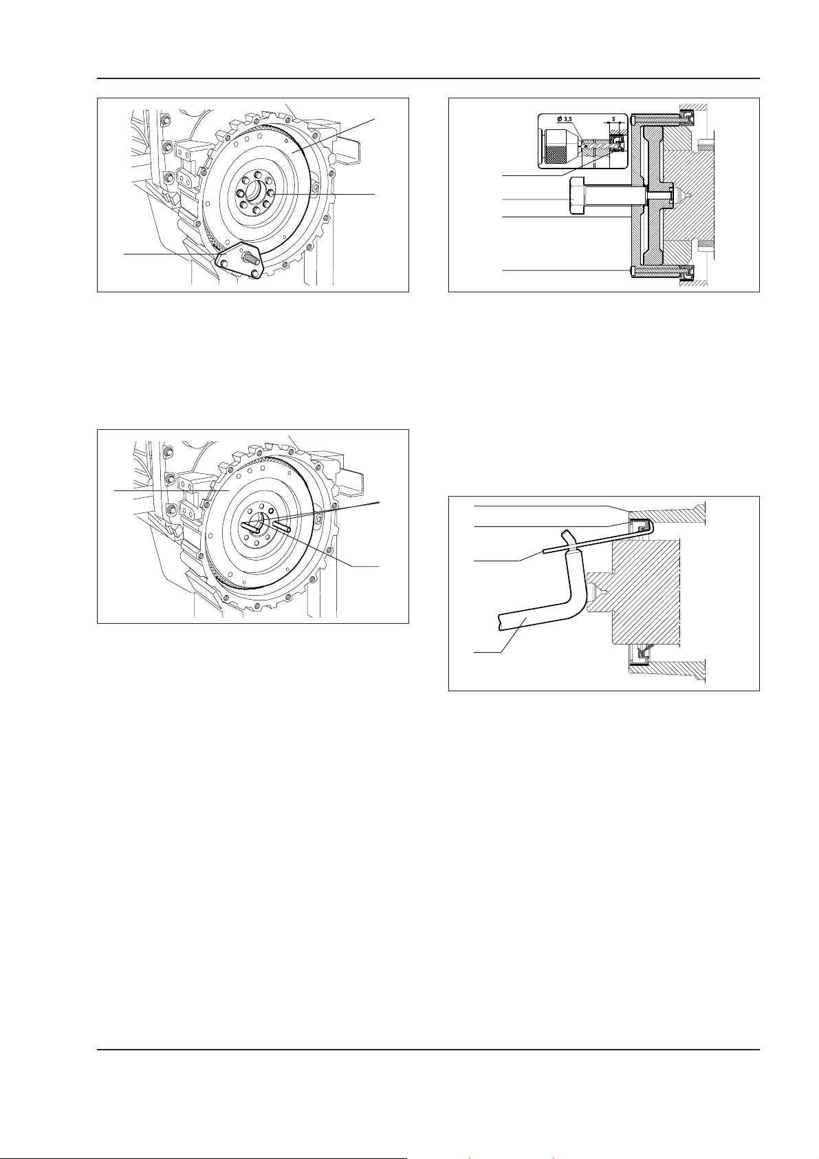
ENGINE
Copyright © New Holland
1 - 43W130/W130TC
4
1
3
2
3
2
4
W110R0137
W110R0139
Install tool 380000144 (2) to loosen screws (3).
Remove tool 380000144 (2).
Remove screws (3) securing engine flywheel (4) to
the crankshaft.
1
2
3
W110R0138
Install two pins (2) of appropriate length into the holes
of crankshaft (3).
Extract engine flywheel (1) so that it is possible to
sling it with a hoist and place it in an appropriate container.
Install tool 380000663 (3) on rear nose ( 5) of the crankshaft.
Drill inner seal ring (1) with a drill (3.5 mm diam.)
through the holes of tool 380000663 (4) for a depth of
5 mm.
Install tool 380000663 (3) on ring (1) tightening the 6
screws (4) provided.
Pullout ring (1) tightening screw (2).
1
2
3
4
W110R0140
Install the appropriate puller (3) of tool 380000669 to
outer seal (2) as described in the figure and pull it out
from front cover (1) using lever (4).
Carefully read personal and machine SAFETY PRECAUTIONS (at the beginning of this manual)
Page 80
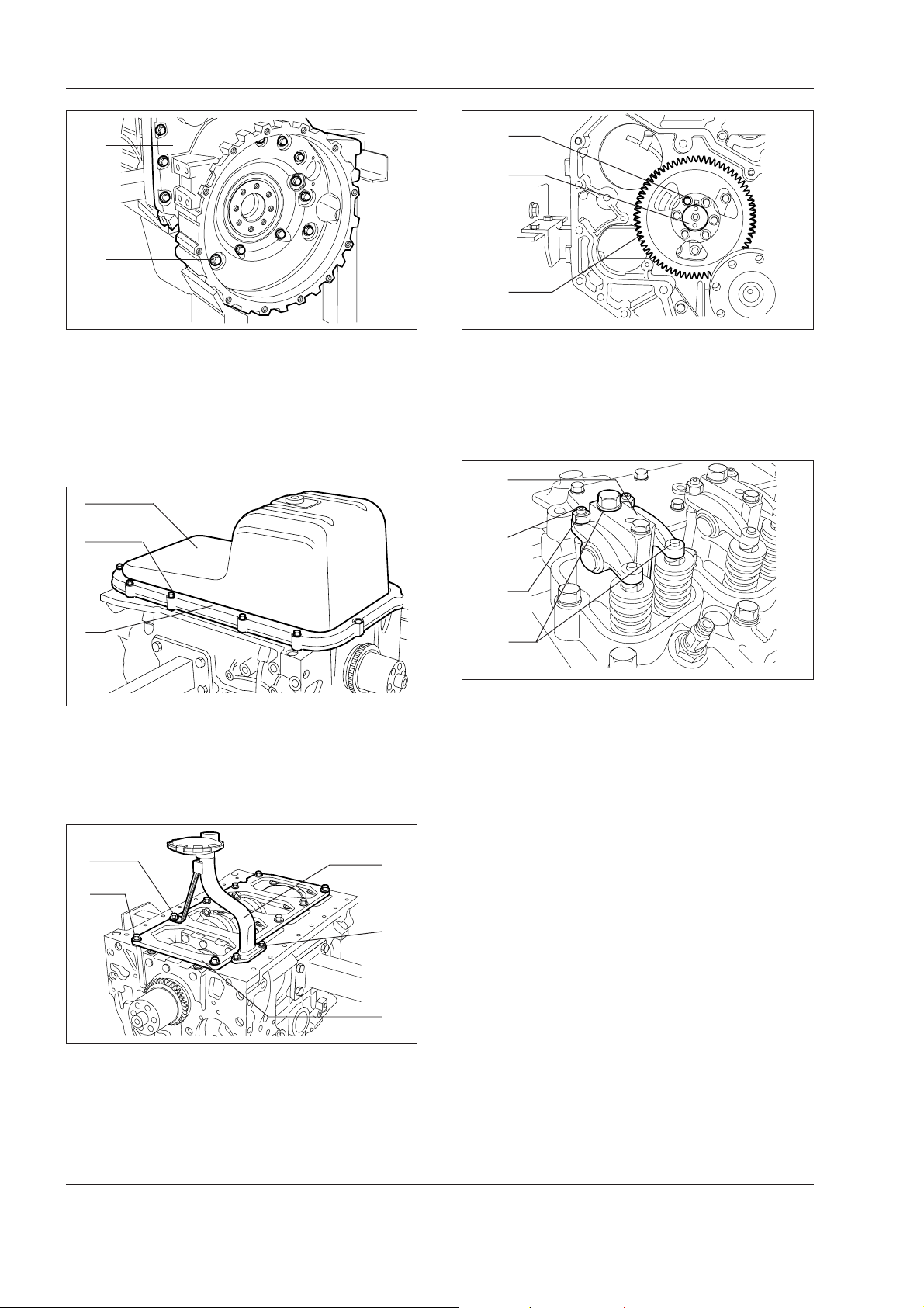
1 - 44 W130/W130TC
Copyright © New Holland
ENGINE
1
2
W110R0141
Remove screws (2) and remove rear cover (1).
Important –
Record the mounting position of screws
(2) since the are dimensionally different.
1
2
1
2
3
W110R0145
Remove screws (1) and gear (3) from camshaft (2).
Removal of rocker arm group
1
2
3
W110R0142
Turn the engine upside down, remove screws (2) plate
(3) and remove oil sump (1).
1
5
2
4
3
W110R0143
3
4
W110R0146
For each cylinder, remove rocker arm group (1) loosening setting nuts (3), loosen adjusters (2) and remove screws (4).
Remove screws (1) and (4) and remove oil suction
strainer (5).
Remove screws (2) and stiffening plate (3).
Carefully read personal and machine SAFETY PRECAUTIONS (at the beginning of this manual)
Page 81
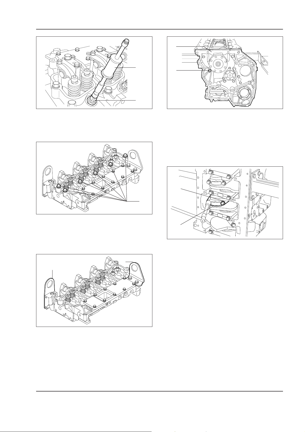
ENGINE
Copyright © New Holland
1 - 45W130/W130TC
1
W110R0147 W110R0150
Pullout injectors (2) using tool (1) 3800001099.
W110R0148
1
2
2
Remove screws (2) and remove timing gears cover
(1).
Important –
Record the mounting position of secur-
ing screws (2) since they have different dimensions.
1
1
Remove screws (1) securing the cylinder head to the
cylinder block.
2
1
W110R0149
Hook the cables to brackets (1) and (2) and lift to
separate the cylinder head from the cylinder block.
2
W110R0151
Remove screws (1) securing conrod (2) caps and remove the caps.
Pullout the pistons complete with conrods from the
top of the cylinder block.
Important –
Keep the half bearings in the relevant
seats, since, in case of their re-use, they must be
reinstalled in the position found at the disassembly.
Carefully read personal and machine SAFETY PRECAUTIONS (at the beginning of this manual)
Page 82
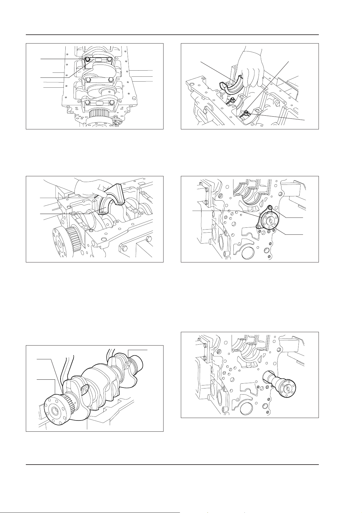
1 - 46 W130/W130TC
Copyright © New Holland
ENGINE
1
2
22
W110R0152
Remove screws (1) and remove main journal caps
(2).
1
2
1
2
W110R0155
Remove main journal half bearings (1).
Remove screws (2) and remove oil nozzles (3).
2
3
1
3
W110R0153
The last but one main journal (1) and relevant support
have a half bearing (2) equipped with thrust washer
Important –
Record the installation position of the
lower and upper half bearings, since in case of their
reinstallation, they must be located in the same position found at the disassembly.
3
1
2
W110R0154
W110R0156
Remove screws (1) and plate (2) securing camshaft
(3).
Important –
Record the installation position of plate
(2).
W110R0157
Extract carefully the camshaft from the cylinder block.
Use tool 75301429 (1) to lift crankshaft (2) from the
cylinder block.
Carefully read personal and machine SAFETY PRECAUTIONS (at the beginning of this manual)
Page 83
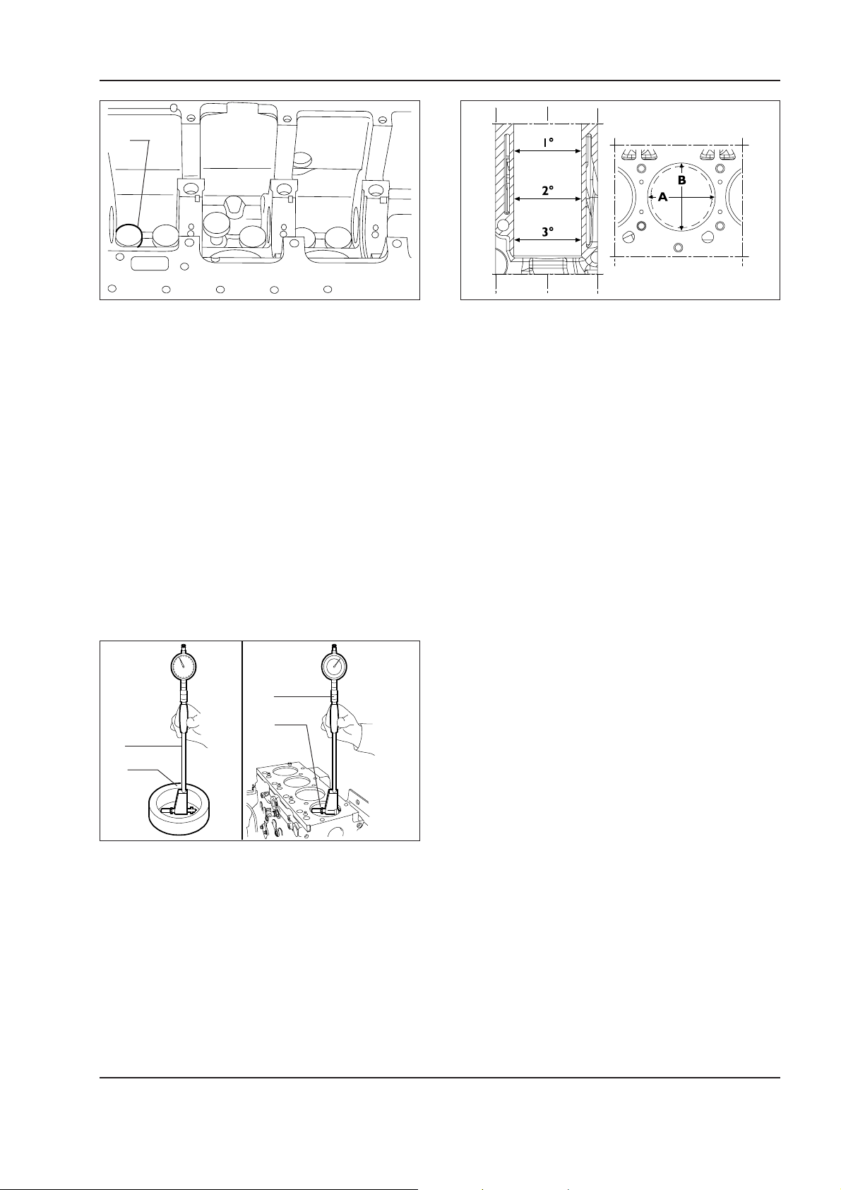
ENGINE
Copyright © New Holland
1 - 47W130/W130TC
1
W110R0158 W110R0160
Extract (1) from the cylinder block.
Repair interventions on cylinder group
Inspections and measurements
Once the disassembly of the engine is over, clean
accurately the cylinder-cylinder block group.
To handle the cylinder group use appropriate eyes.
Check accurately that the cylinder block is free from
cracks.
Check the conditions of the machining plugs. Should
they be found rusty or their sealing is in doubts, replace them.
Inspect the surface of the cylinder sleeves. They must
be free from signs of seizing, scratches, out-of-round,
tapering or excessive wear.
1
2
1
The measurements must be done on each single cylinder, at three different heights of the sleeve and on
two planes perpendicular between them: one parallel
to the longitudinal axis of the engine (A) the other one
perpendicular (B). The maximum wear is normally
found on the latter plane and in correspondence with
the first measurement
In the event an out-of round, tapering or any wear is
found, re-bore and re-grind the cylinder sleeves. The
reboring of the cylinder sleeves must be done in relation with the diameter of spare pistons oversized
0.5 mm with respect to the nominal size and the prescribed installation clearance.
2
The measurement of the inner diameter of the cylinder sleeves, the amount of any out-of-round, tapering
or wear is done with bore gauge 99395687 (1) equipped
with a dial gauge previously zeroed on caliper ring (2)
with the correct diameter of the cylinder sleeve.
Note –
Should the ring caliper be unavailable, use a
micrometer to zero the dial gauge.
W110R0159
Carefully read personal and machine SAFETY PRECAUTIONS (at the beginning of this manual)
Page 84
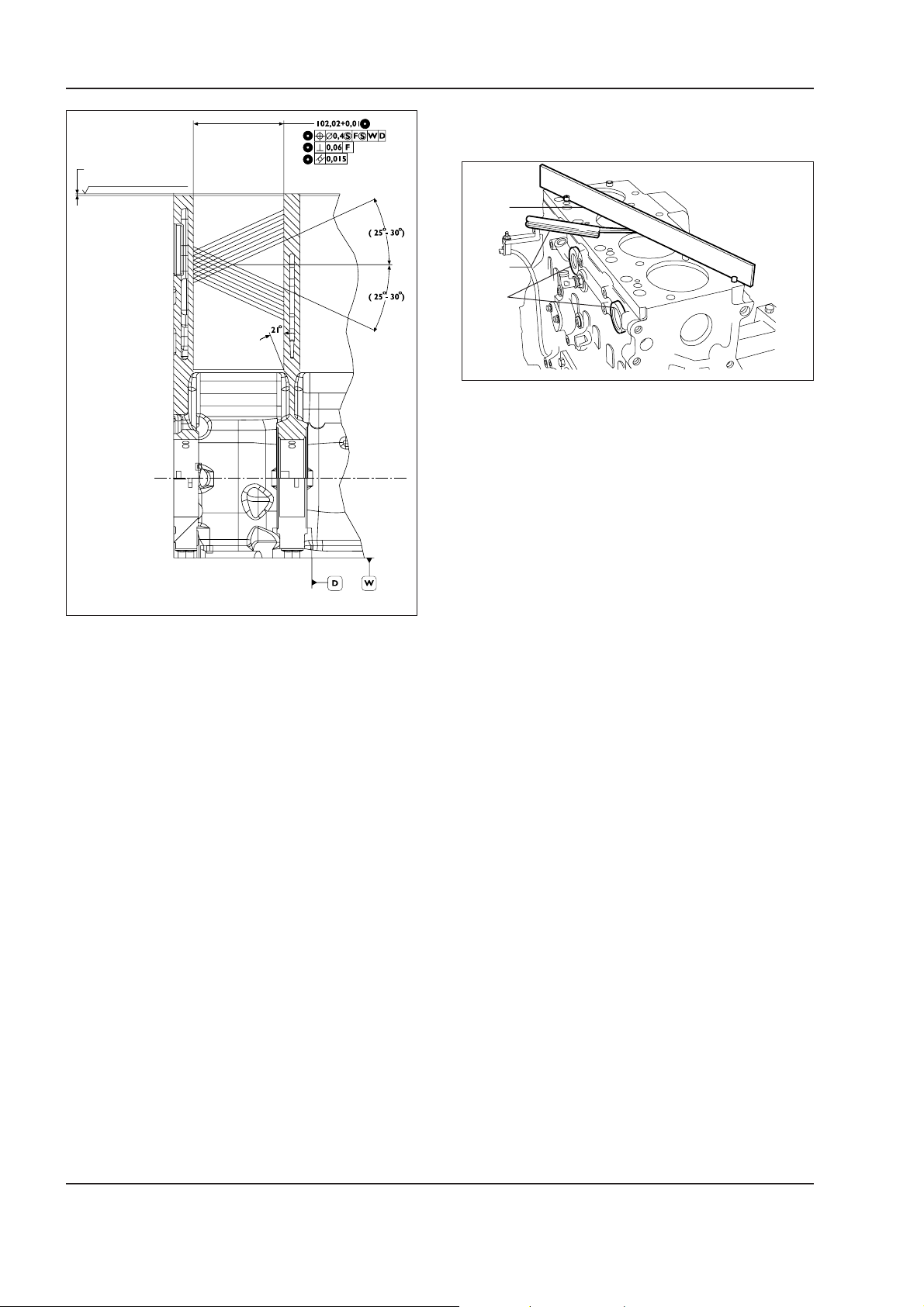
1 - 48 W130/W130TC
Copyright © New Holland
ENGINE
Checking the mating face of the cylinder head
on the cylinder block
1,25 ± 0,25 mm
Rz 12,0 ISO CUT OFF 2,5
2
3
1
W110R0162
Check that the mating face of the cylinder head on
the cylinder group does not show any deformation.
This check can be done, after removing dowels (4)
using a calibrated ruler (2) and feeler gauge (3).
After identifying any zone of deformation, grind the
mating face using an appropriate grinding machine.
The planarity discrepancy must not exceed 0.075 mm.
W110R0161
Important
– In case of re-boring, all the cylinder
sleeves must have the same oversizing (0.5 mm).
Check the seats of the main journal bearings, proceeding as follows:
- install the main journal caps without bearings;
- tighten the securing screws to the prescribed
torque;
- using an appropriate bore gauge, check that the
diameter of the seats has the prescribed value.
Should a higher value be measured, replace the cylinder block.
Note –
the grinding of the cylinder block can be done
only when it is ascertained that, once the work is done,
the protrusion of the piston from the cylinder sleeve
does not exceed the prescribed value.
Check the conditions of machining plugs (1) of the
cylinder group. Should they be found rusty or their
sealing is in doubts, replace them.
Once the grinding is over, remake the bevel of the
cylinder sleeves.
Carefully read personal and machine SAFETY PRECAUTIONS (at the beginning of this manual)
Page 85
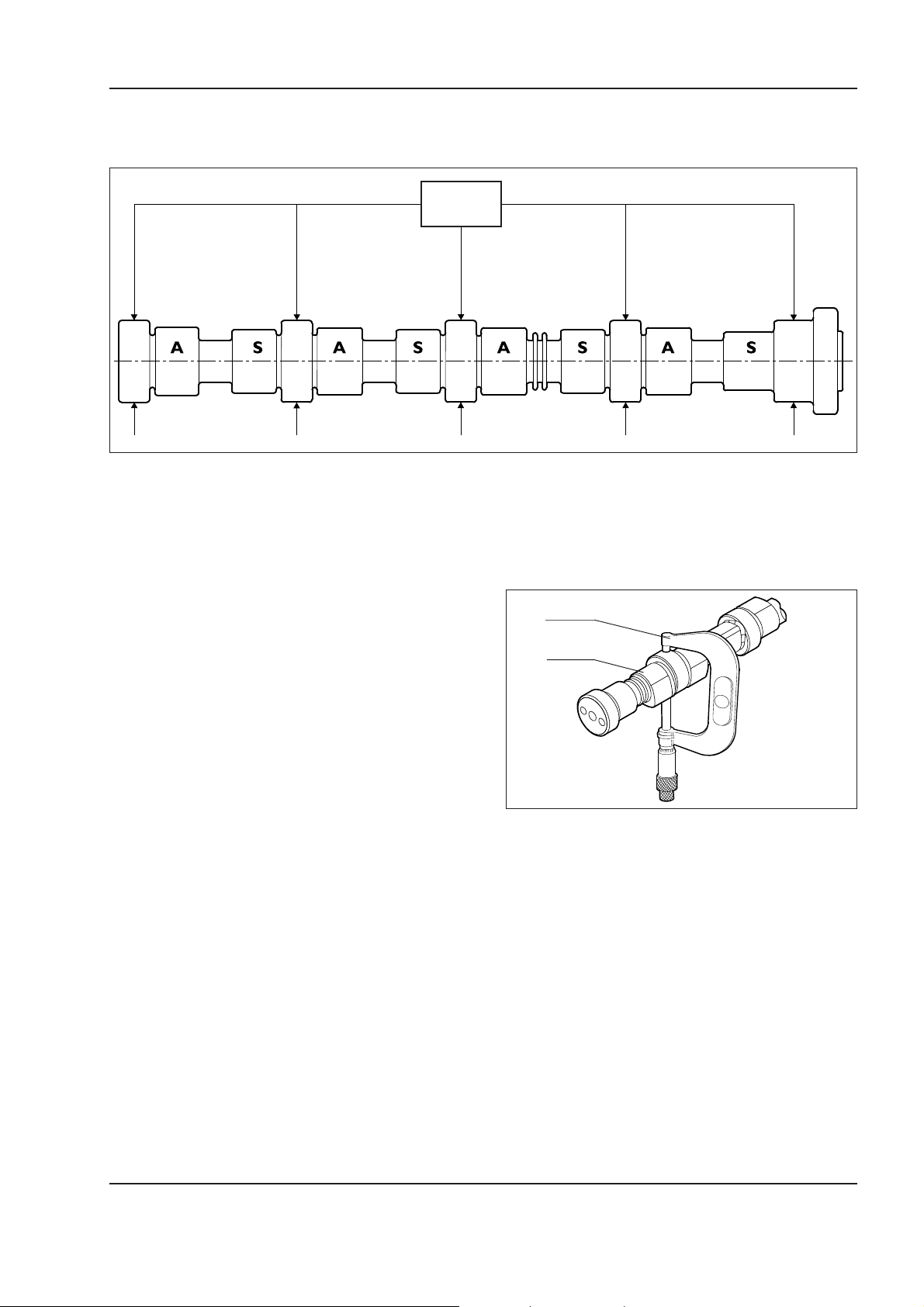
ENGINE
Copyright © New Holland
Timing
Camshaft
53.995 mm
54.045 mm
Camshaft main data
The data provided refer to the normal diameter of the journals.
1 - 49W130/W130TC
W110R0163
The surfaces of the camshaft journals must be extremely smooth. Should they show any trace of seizure or scratches, it is advantageous to replace the
camshaft and relevant bushes.
Checking the cam lifting and journals alignment
Place the camshaft on centres and using a centesimal
dial gauge located on the central journal, check that
the alignment error does not exceed 0.04 mm, otherwise, replace the camshaft. Also, check the cam lifting. It must result 7.239 mm for the exhaust cams
and 6.045 mm for the intake ones. Should different
values be measured, replace the camshaft.
1
2
W110R0164
Check the diameter of camshaft journals (2) using
micrometer (1) on two axes perpendicular between
them.
Carefully read personal and machine SAFETY PRECAUTIONS (at the beginning of this manual)
Page 86
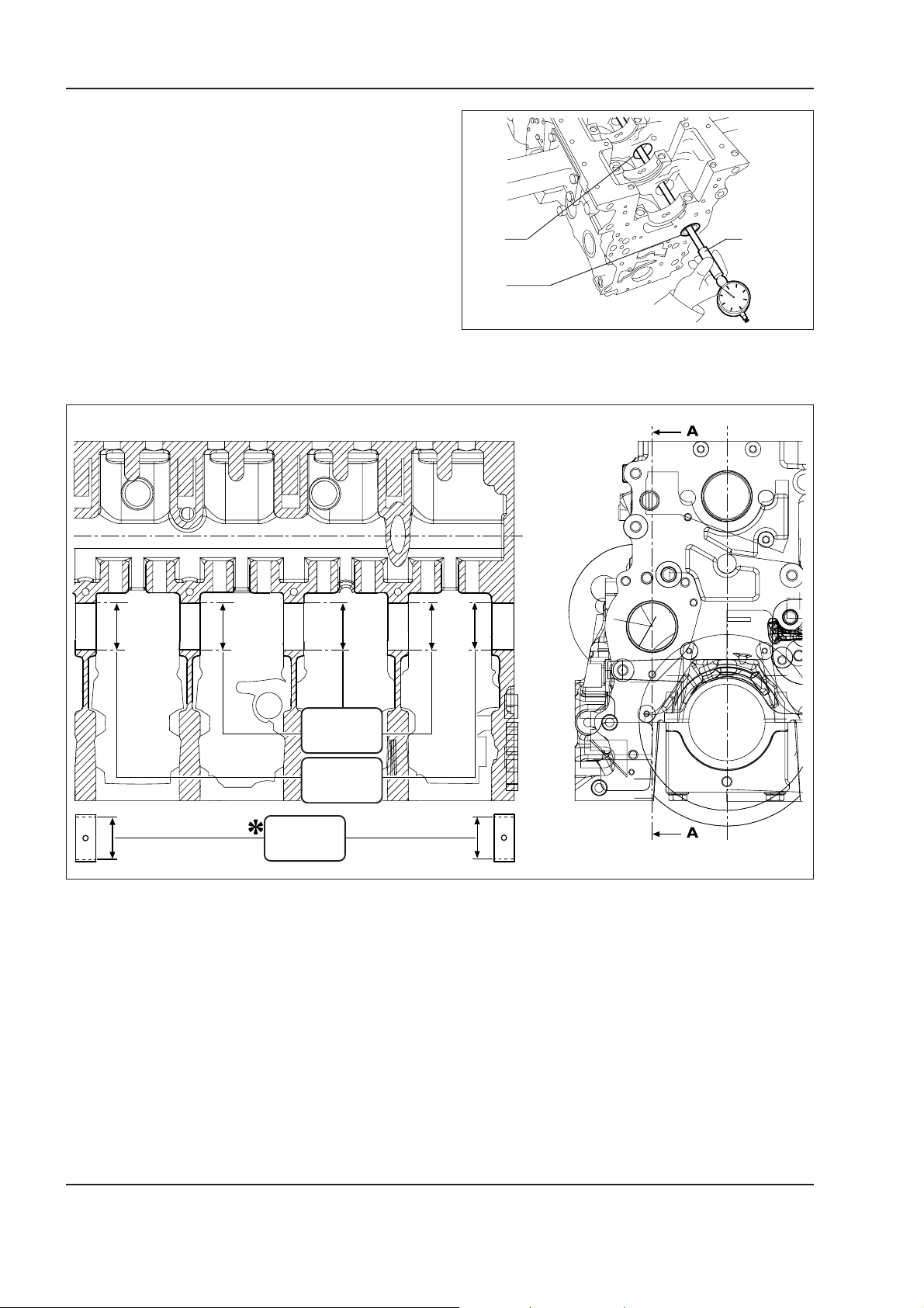
1 - 50 W130/W130TC
Copyright © New Holland
ENGINE
Bushes
Camshaft bushes (2) must be tight mounted into their
seats.
The inner surfaces must be free from traces of seizure or wear.
Measure the diameter of the camshaft front and rear
bushes (2) and intermediate seats (1) using bore gauge
1
3
(3).
The measurements must be taken on two axes perpendicular between them.
Sect. A-A
2
W110R0165
54.089 mm
54.139 mm
59.222 mm
59.248 mm
54.083 mm
54.147 mm
Main data of bushes for camshaft and relevant seats
* Dimension to be obtained after press fitting the bushes.
W110R0166
Carefully read personal and machine SAFETY PRECAUTIONS (at the beginning of this manual)
Page 87
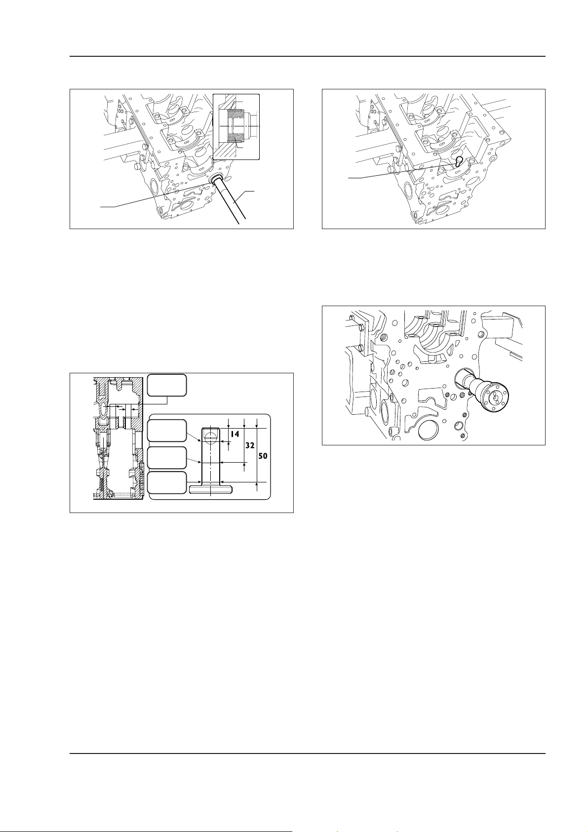
ENGINE
Copyright © New Holland
1 - 51W130/W130TC
Replacing the bushes
2
2
3
2
W110R0167
Use punch 75301885 (2) and handle 380000668 (3) to
remove and install front and rear bushes (1).
Important -
When installing bushes (1), place the so
that the lubrication holes coincide with the holes on
the cylinder block seats.
Tappets
Installing the tappets -Camshaft
1
W110R0168
Lubricate tappets (1) and install them into the relevant
seats on the cylinder block.
16.000 mm
16.030 mm
15.929 mm
15.959 mm
15.965 mm
15.980 mm
15.929 mm
15.959 mm
W110R0169
Main data of tappets and relevant seats on the cylinder block
W110R0170
Lubricate the camshaft journals and install the camshaft, paying attention that, during this operation, the
bushes and the journals are not damaged.
Carefully read personal and machine SAFETY PRECAUTIONS (at the beginning of this manual)
Page 88
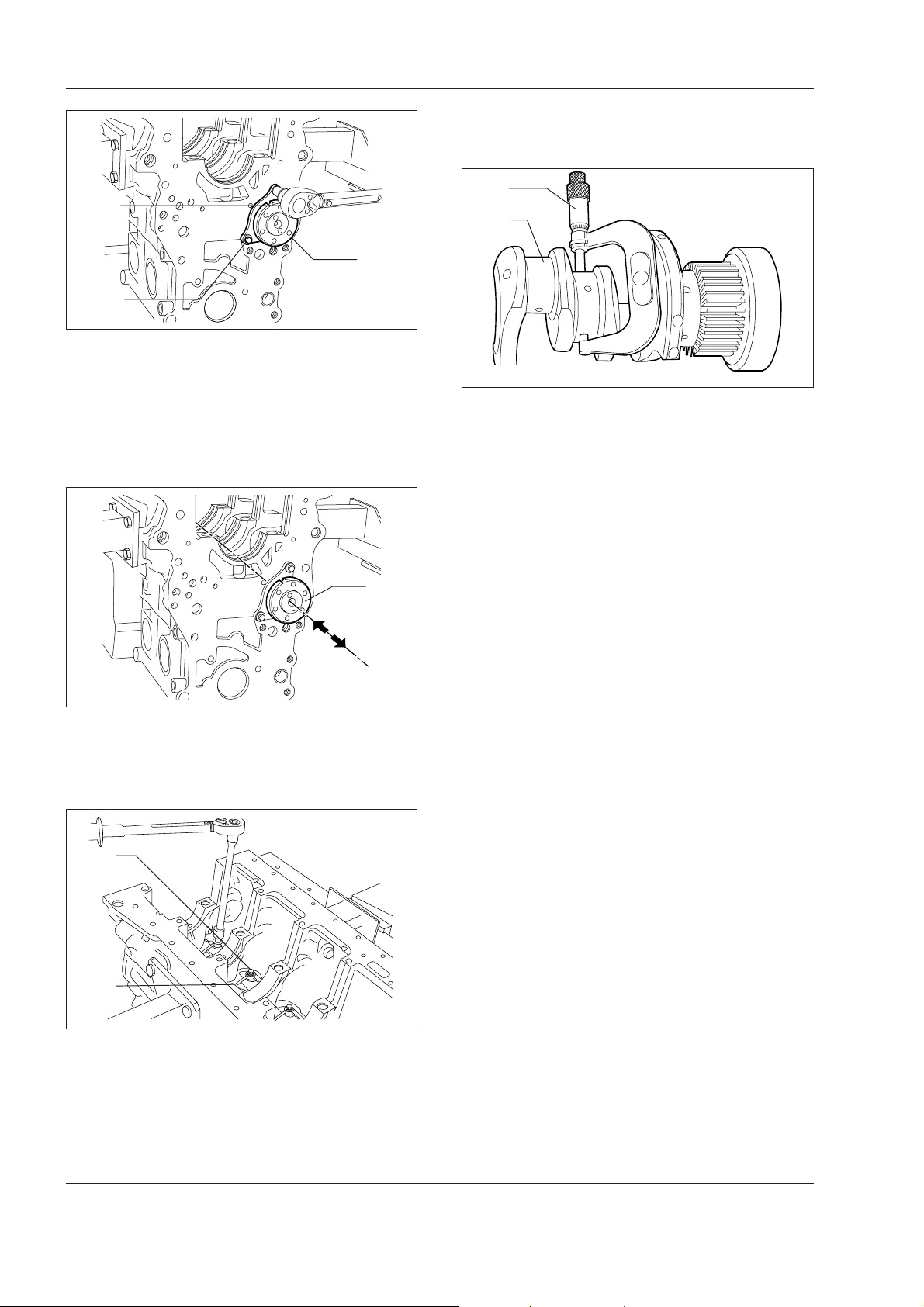
1 - 52 W130/W130TC
Copyright © New Holland
ENGINE
Crankshaft
Measuring main and conrod journals
1
1
2
3
2
W110R0171
Place plate (1) securing camshaft (3) with the slot
directed toward the upper side of the cylinder block
W110R0174
and the stamping toward the operator, tighten screws
(2) to the prescribed torque.
Should excessive traces of seizing, scratches or out
of round be found, it is necessary to re-grind the journals. Prior to grinding journals (2) measure the crankshaft journals with micrometer (1) and define to what
diameter the journals must be undersized.
Check the axial play of camshaft (1).
1
1
W110R0172
Note –
It is recommended to record the values meas-
ured on a table.
2
Install nozzles (2) and tighten securing screws (1) to
the prescribed torque.
Carefully read personal and machine SAFETY PRECAUTIONS (at the beginning of this manual)
W110R0173
Page 89
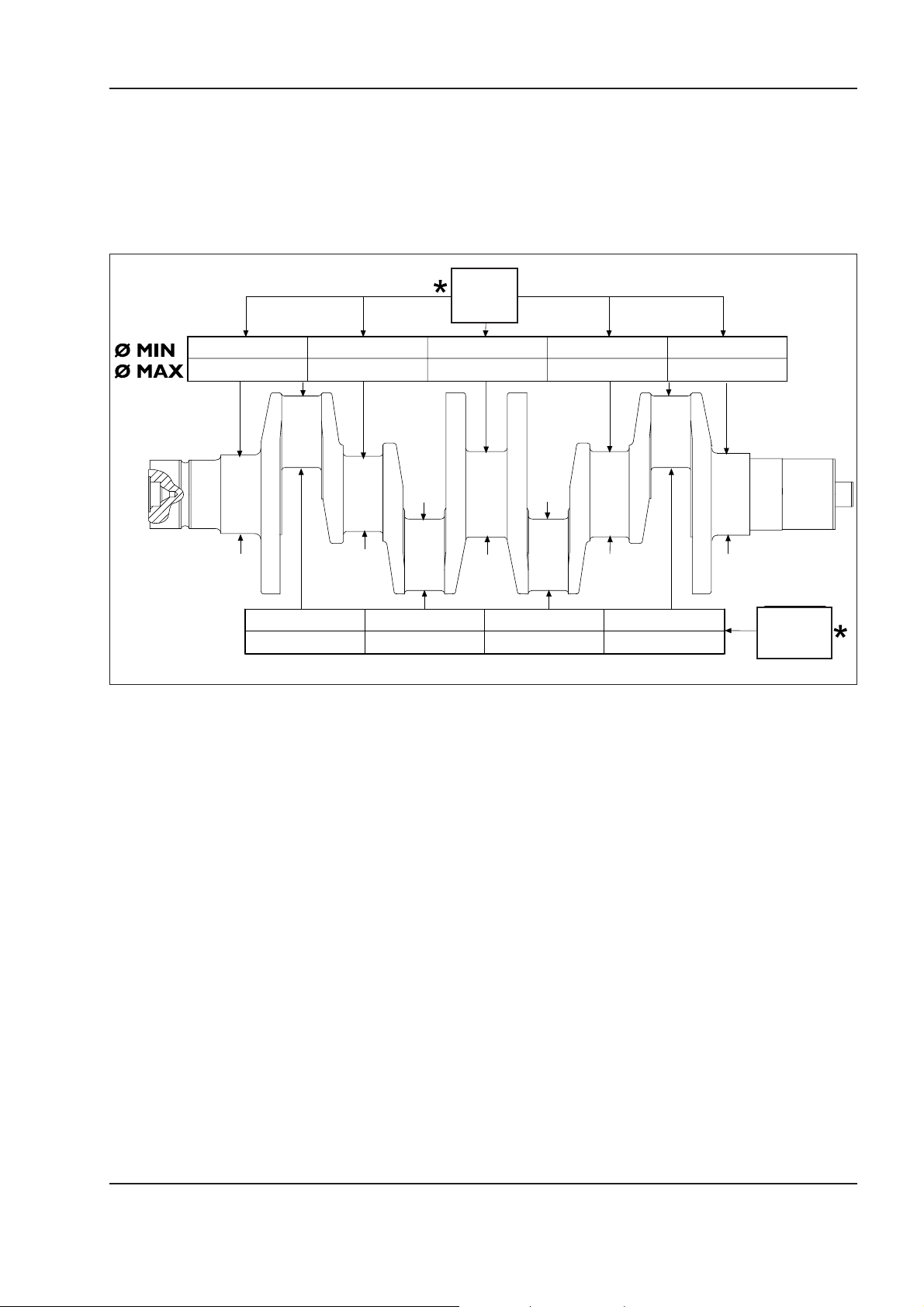
ENGINE
Copyright © New Holland
1 - 53W130/W130TC
The undersizing classes are 0.250; 0.500 mm.
Important –
The main and conrod journals must always be reground to the same undersize class.
The undersizing performed on the main and conrod
journals, must be identified by an appropriate stamping on the side of crank no. 1.
82.99 mm
83.01 mm
For undersized conrod journals by letter M.
For undersized main journals by letter B.
For undersized main and conrod journals by letters
MB.
68.99 mm
69.01 mm
W110R0175
Data on which to record the values relative to the measurement of crankshaft main and conrod journals
* Nominal value.
Carefully read personal and machine SAFETY PRECAUTIONS (at the beginning of this manual)
Page 90
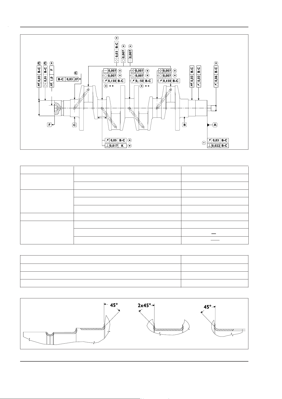
1 - 54 W130/W130TC
Copyright © New Holland
ENGINE
W110R0176
Main crankshaft tolerances
Tolerances Features of the subject of tolerance Symbol
Shape
Roundness O
Cilindricity /O/
Parallelism //
Direction
Perpendicularity ⊥
Straightness —
Position
Concentricity or radial run-out "
Circular oscillation !
Oscillation
Total oscillation !!
Tapering
#
Class of importance given to the feature of the product Symbol
Critical
Important
Secondary
©
⊕
–
!
Journal
timing side
Carefully read personal and machine SAFETY PRECAUTIONS (at the beginning of this manual)
Intermediate
journals
First journal
upper side
W110R0177
Page 91
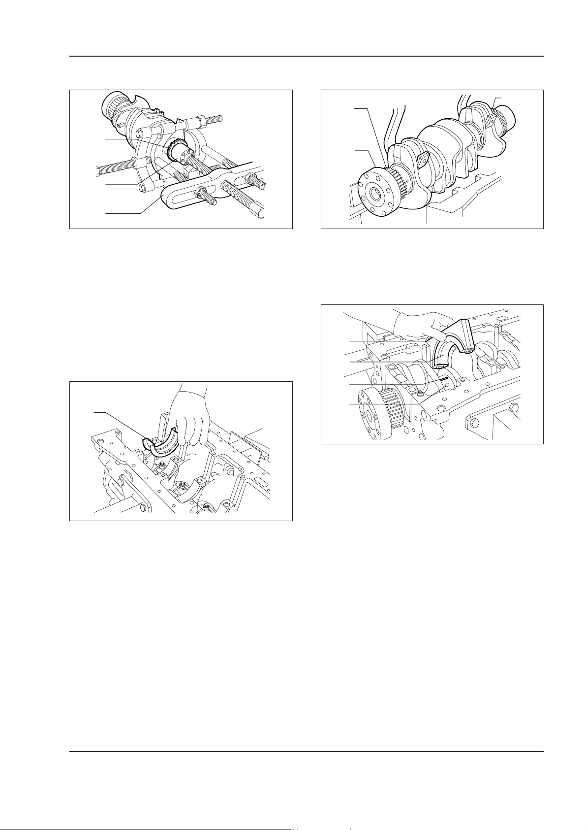
ENGINE
Copyright © New Holland
1 - 55W130/W130TC
Replacing the oil pump drive gears
1
2
3
W110R0178
Check that the teeth of gear (1) installed on crankshaft (2) are undamaged and free from wear; otherwise pull them using puller (3).
When installing a new gear, it is necessary to warm it
up for 10 minutes in an oven at a temperature of
180 °C (355 °F) and install it on the crankshaft, mounting the key as well.
Measuring the main journal mounting clearance
3
1
2
W110R0180
Install crankshaft (1) on which gears (2) and (3) are
mounted.
1
Installing the main journal bearings
1
W110R0179
Important –
When it is found that the main journal
bearings must not be replaced, they are reinstalled in
the same sequence and position they were before the
disassembly.
Main journal bearings (1) are supplied as spare parts
undersized 0.250 to 0.500 mm on the inner diameter.
Important –
Do not attempt adapting the bearings.
2
3
4
W110R0181
Check the clearance between main journal of the
crankshaft and the relevant bearings, operating as
follows:
- clean accurately the components and eliminate all
races of oil;
- place a piece of calibrated rod (3) on crankshaft
main journals (4) parallel to the longitudinal axis;
- install caps (1), complete with half bearings (2) on
the relevant supports.
Clean accurately main journal half bearings (1) having the lube hole and install them in the relevant seats.
The last but one main half-bearing (1) is equipped with
thrust half rings.
Carefully read personal and machine SAFETY PRECAUTIONS (at the beginning of this manual)
Page 92
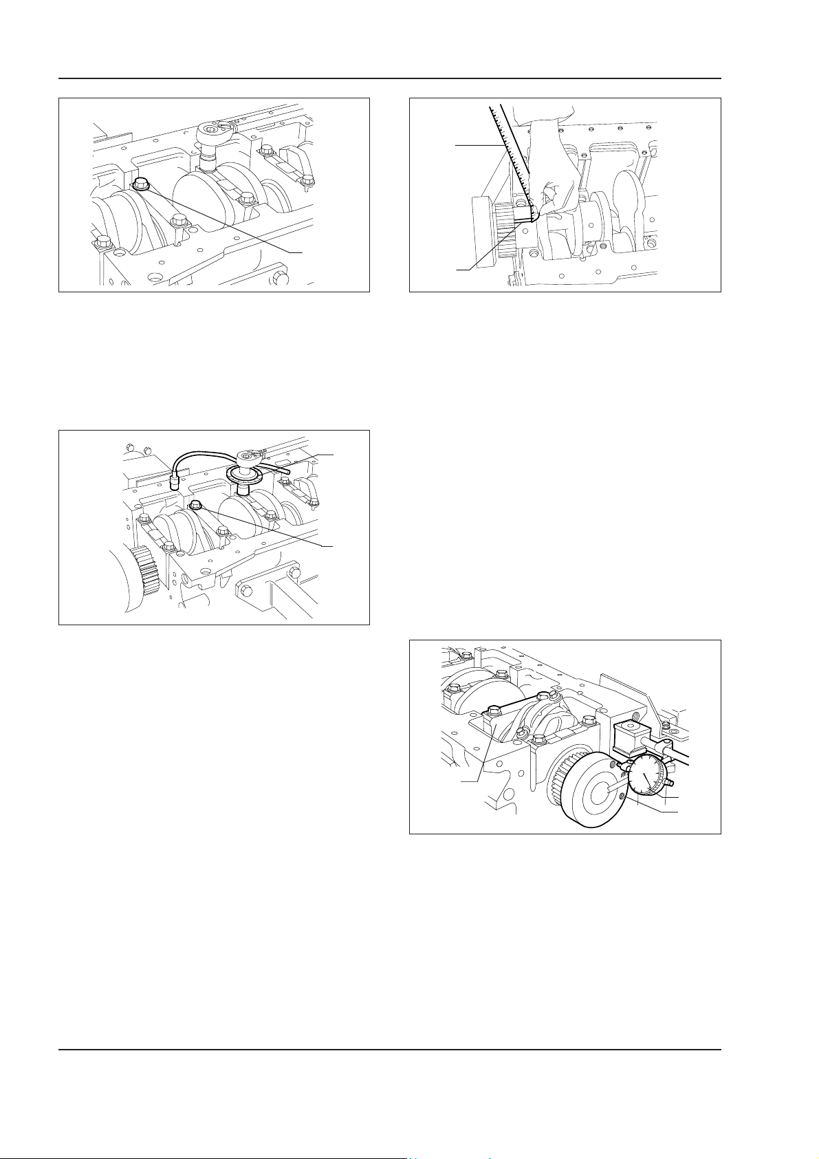
1 - 56 W130/W130TC
Copyright © New Holland
ENGINE
1
1
2
W110R0182
W110R0184
Tighten screws (1) pre-lubricated and tighten them in
three subsequent phases.
-1st phase with torque wrench to 50 ±6 Nm.
-2nd phase with torque wrench to 80 ± 6 Nm.
1
2
W110R0183
-3rd phase with tool 75301460 (1) installed as indicated in the figure and tighten screws (2) further to
an angle of 60 ± 5°.
- remove the caps from the supports.
The play between main journal bearings and the rel-
evant journals is measured by comparing the width
taken by calibrated wire (2) in the point of maximum
squeezing, with the scale provided on wrapping (1)
containing the wire.
The numbers listed by the scale indicate the clearance in mm of the match.
Should a clearance different from the prescribed value
be measured, replace the half bearings and repeat
the measurement. Once the prescribed clearance is
achieved, lubricate the main journal bearings and install definitely the supports, tightening the securing
screws, as previously described.
Checking the crankshaft thrust clearance
Carefully read personal and machine SAFETY PRECAUTIONS (at the beginning of this manual)
1
2
3
W110R0185
The measurement of the thrust clearance is made by
placing a dial gauge (2) with a magnetic base on crankshaft (3) as indicated in the figure. Normal mounting
clearance is 0.068 to 0.410 mm.
Should a higher clearance be measured, replace the
half bearings on the rear last but one main journal (1)
equipped with thrust washer and repeat the check of
the clearance between crankshaft journals and half
bearings.
Page 93
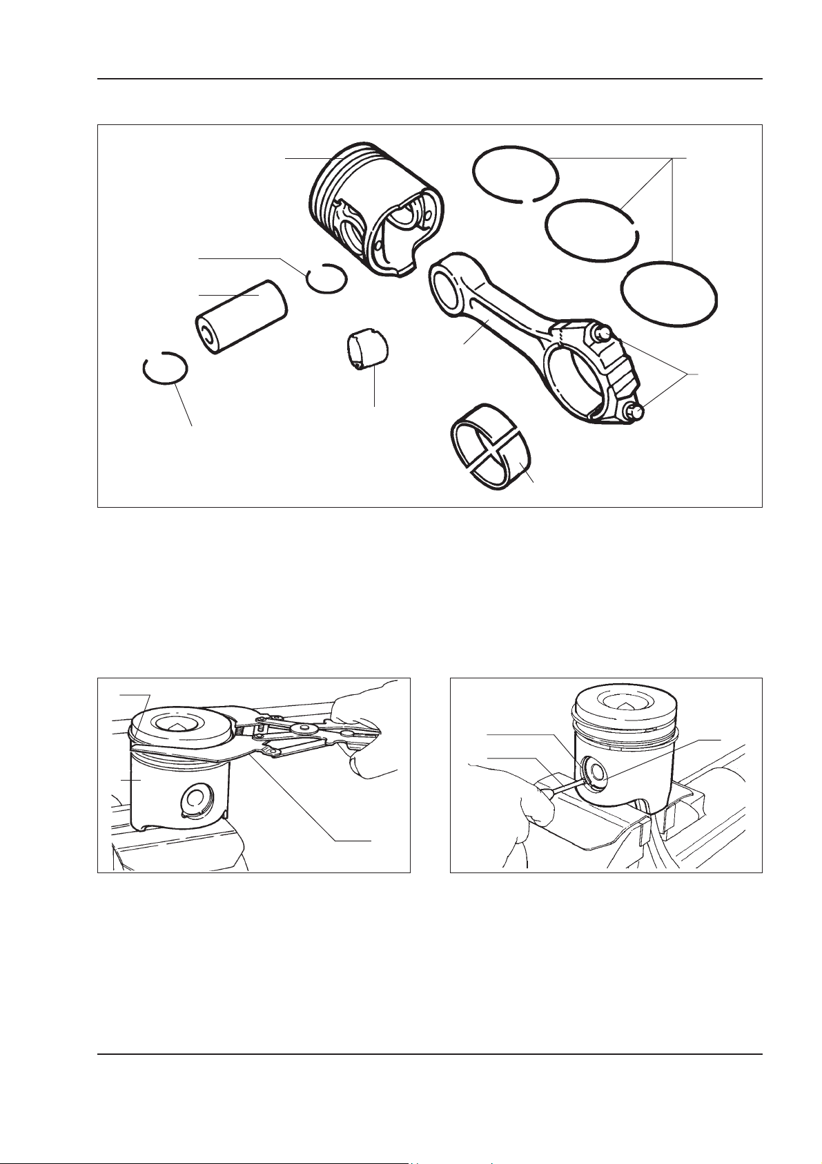
Conrod - Piston assembly
Copyright © New Holland
ENGINE
1 - 57W130/W130TC
3
1
2
8
1
Parts making up the conrod piston assembly
4
7
5
6
W110R0186
1. Circlips - 2. Pin - 3. Piston - 4. Piston rings - 5. Screws - 6. Half bearings - 7. Conrod - 8. Bush.
Note –
0.5 mm oversized pistons are supplied as spare parts.
1
2
3
2
3
W110R0187
Disassembly of piston rings (1) from piston (2) using
pliers 380000221.
The disassembly of piston pin (1) circlips (2) is done
using scriber (3).
1
W110R0188
Carefully read personal and machine SAFETY PRECAUTIONS (at the beginning of this manual)
Page 94
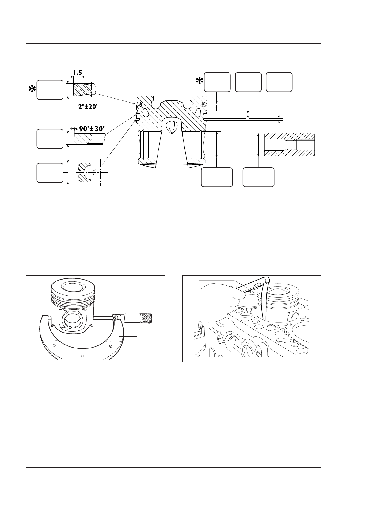
1 - 58 W130/W130TC
Copyright © New Holland
ENGINE
2.560 mm
2.605 mm
2.310 mm
2.340 mm
3.075 mm
4.000 mm
Piston main data
Pistons
2.69 mm
40.0060 mm
40.012 mm
2.425 mm
2.445 mm
39.9968 mm
40.0032 mm
4.040 mm
4.060 mm
W110R0189
Measuring the piston diameter
1
2
W110R0190
Measurement of the diameter of piston (1) using micrometer (2) to determine the mounting clearance.
Note –
The diameter must be measured at 61 mm
from the skirt of the piston.
1
W110R0191
The clearance between piston and cylinder sleeve can
be measured also using feeler gauge (1) as indicated
in the figure.
Carefully read personal and machine SAFETY PRECAUTIONS (at the beginning of this manual)
Page 95
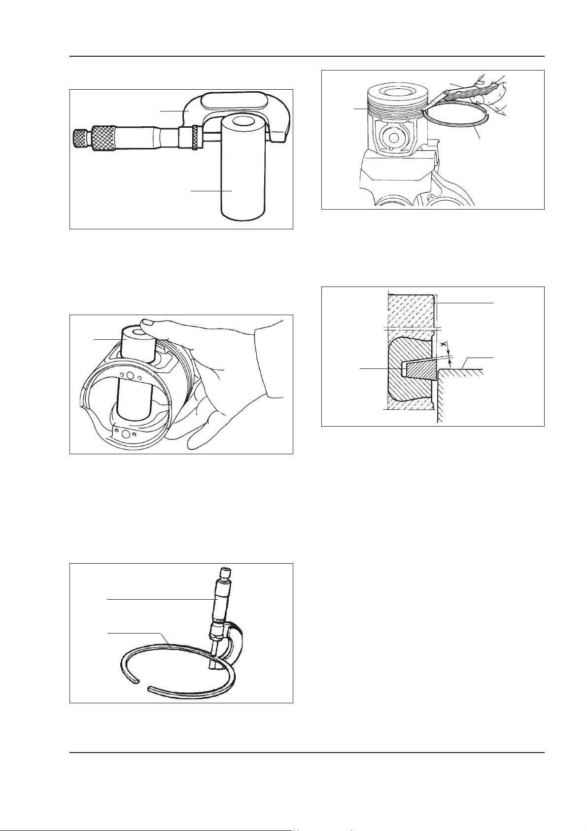
ENGINE
Copyright © New Holland
1 - 59W130/W130TC
Piston pins
2
1
W110R0192
Measuring the diameter of piston pin (1) using micrometer (2).
Conditions for a correct pin-piston matching
1
1
2
1
3
W110R0195
Check the clearance between piston ring (3) of the
3rd groove and the relevant seat on piston (2) with
feeler gauge (1).
1
3
2
W110R0193
Lubricate pin (1) and the relative seats on the piston
bosses with engine oil. The pin must slide in under a
light finger pressure and must not come-out under its
own weight.
Piston rings
1
2
W110R0194
W110R0196
Diagram for the measurement of clearance X Trapezoidal rings
Due to the particular shape of the first trapezoidal
piston ring, the clearance between seat and the ring
itself is measured in the following manner: have piston (1) protruding from the cylinder block so that ring
(2) involved protrudes about half from cylinder sleeve
(3).
Under these condition, use a feeler gauge to measure
clearance (X) between ring and seat. Such clearance
must be of the prescribed value.
Check the thickness of piston rings (2) using micrometer (1).
Carefully read personal and machine SAFETY PRECAUTIONS (at the beginning of this manual)
Page 96
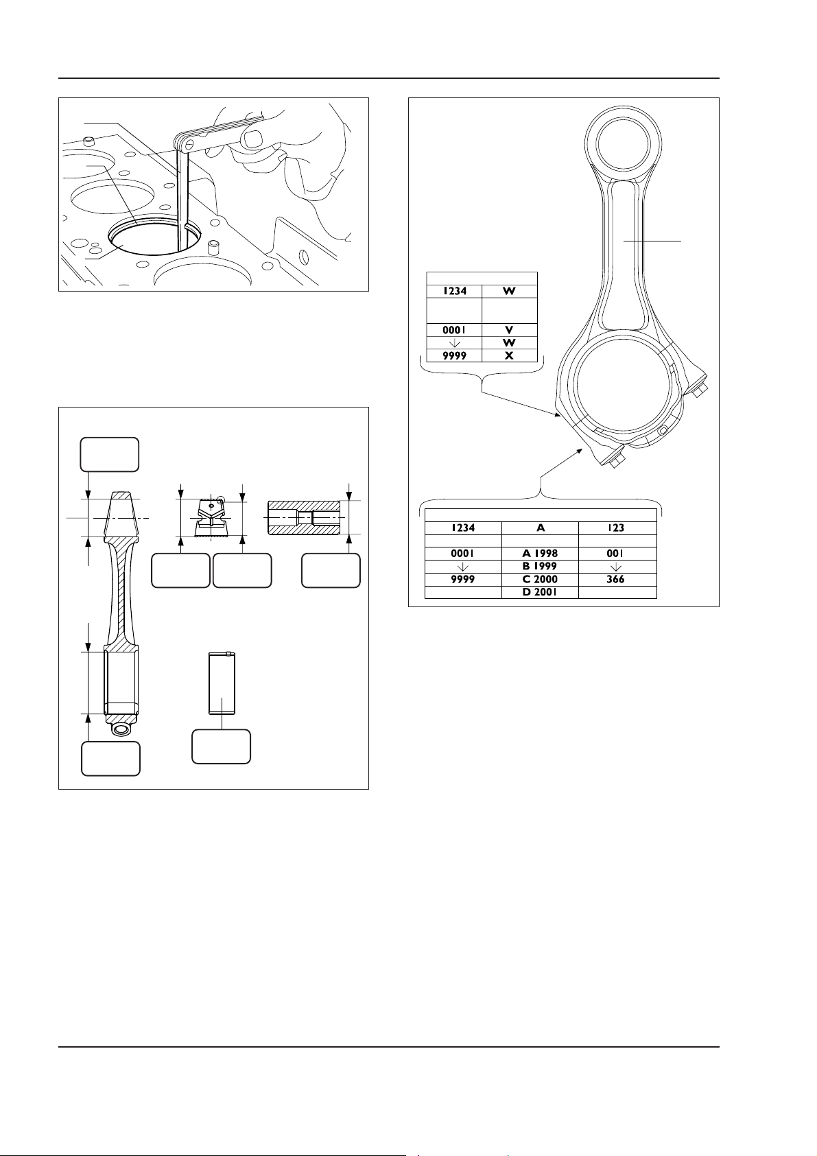
1 - 60 W130/W130TC
Copyright © New Holland
ENGINE
1
2
∗
3
W110R0197
CONROD BODY
Measuring the clearance between the tips of piston
rings (2) installed into cylinder sleeve (3) using feeler
gauge (1).
Conrods
42.987 mm
43.013 mm
43.279 mm
43.553 mm
77.075 mm
78.250 mm
40.019 mm
40.033 mm
1.955 mm
1.968 mm
39.9968 mm
40.0032 mm
W110R0198
Main data for conrod, piston pin bush and half
bearings
* Dimension of inner diameter to be obtained after
press fitting into the bush conrod big end and re-boring.
CONROD
No.
CONROD No. YEAR DAY
Important –
WEIGHT
CONROD CAP
W110R0199
Each conrod is marked:
On the body and cap, by a number indicating their
matching and the cylinder in which it is installed.
Thus, in case of replacement, it is necessary to proceed with the numbering of the new conrod with the
same number of the one replaced.
On the conrod body, a letter indicates the weight class
of the conrod installed in production:
- V, 1820 to 1860 (identified by a yellow mark);
- W, 1861 to 1900 (identified by green mark),
- X, 1901 to 1940 (identified by blue mark).
Spare conrods are supplied under class W and marked
green*.
Non removal of material is allowed.
** Dimension not measurable under free state.
Important –
The conrod-conrod cap matching surfaces
are knurled to improve the fitting.
Consequently, it is recommended not to remove the
knurling.
Carefully read personal and machine SAFETY PRECAUTIONS (at the beginning of this manual)
Page 97
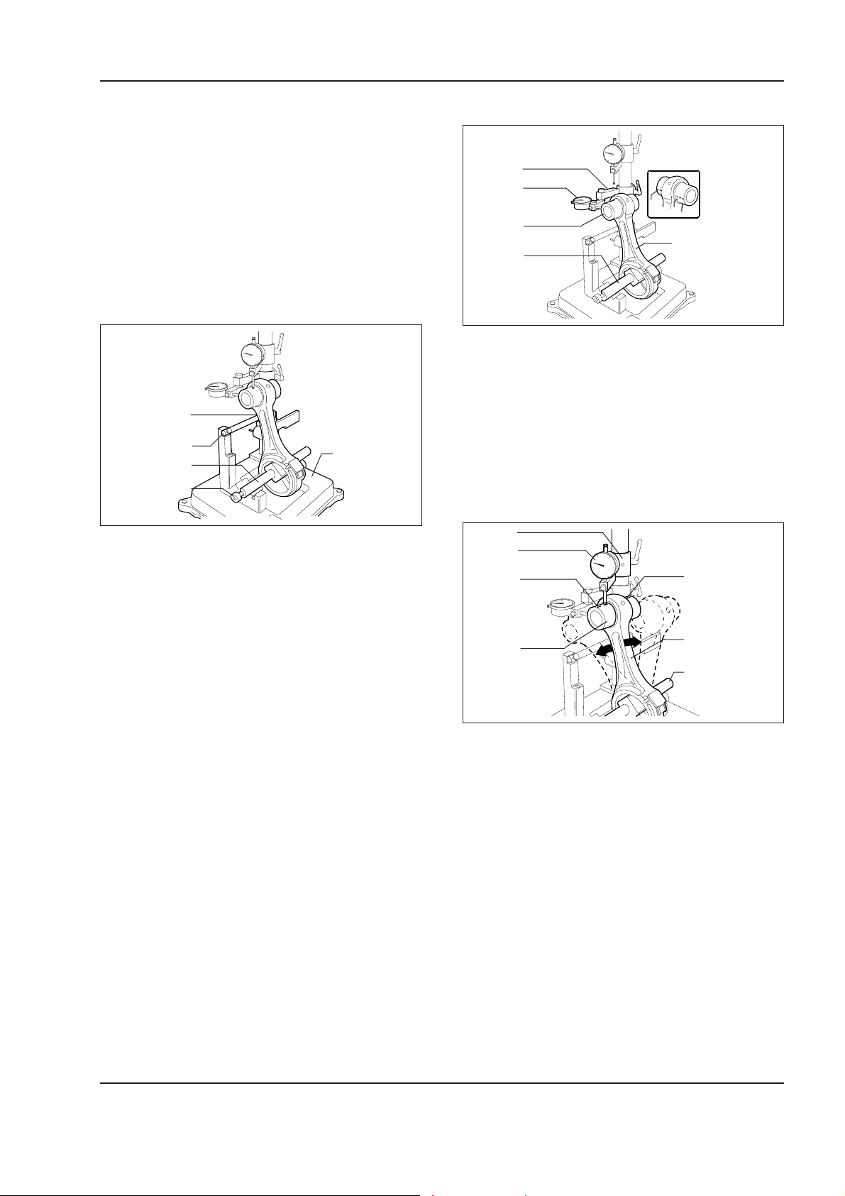
ENGINE
Copyright © New Holland
1 - 61W130/W130TC
Bushes
Check that bush in the big end of the conrod is not
free and that is free from scratches or seizing. Otherwise, replace it.
The disassembly and reassembly are done using an
appropriate punch.
During the press fitting make sure scrupulously that
the oil passage holes on the bush and the conrod big
end coincide. Use a boring machine to re-bore the
bush, so that the prescribed diameter is obtained.
Checking the conrod
1
2
3
5
4
W110R0200
Check the parallelism of the conrod (1) axes using
device 75301461 (5) operating as follows:
- install conrod (1) on the mandrel of tool 75301461
(5) and secure it with screw (4);
Check of torsion
1
2
B
A
3
5
4
W110R0201
Check the torsion of conrod (5) comparing two points
(A and B) of pin (3) on the horizontal plane of the
conrod axis.
Place support (1) of dial gauge (2) so that the latter is
pre-loaded ~ 0.5 mm on pin (3) in point (A) and zero
dial gauge (2).
Move mandrel (4) with conrod (5) and compare on the
opposite side (B) of pin (3) for any discrepancy: the
difference between (A and B) must not exceed 0.08
mm.
1
2
C
D
- place mandrel (3) on “V” blocks resting conrod (1)
on stopping bar (2).
3
5
4
W110R0202
Checking the flexion
Check the flexion of conrod (5) comparing two points
(C and D) of pin (3) on the vertical plane of the conrod
axis. Place vertical support (1) of dial gauge (2) so
that the latter rests on pin (3) point (C). Oscillate the
conrod for and back searching for the highest position of the pin and under this condition, zero the dial
gauge (2). Move the mandrel with conrod (5) and repeat on the opposite side (D) of pin (3) the check of
the highest point. The difference between point (C)
and point (D) must not exceed 0.08 mm.
Carefully read personal and machine SAFETY PRECAUTIONS (at the beginning of this manual)
Page 98
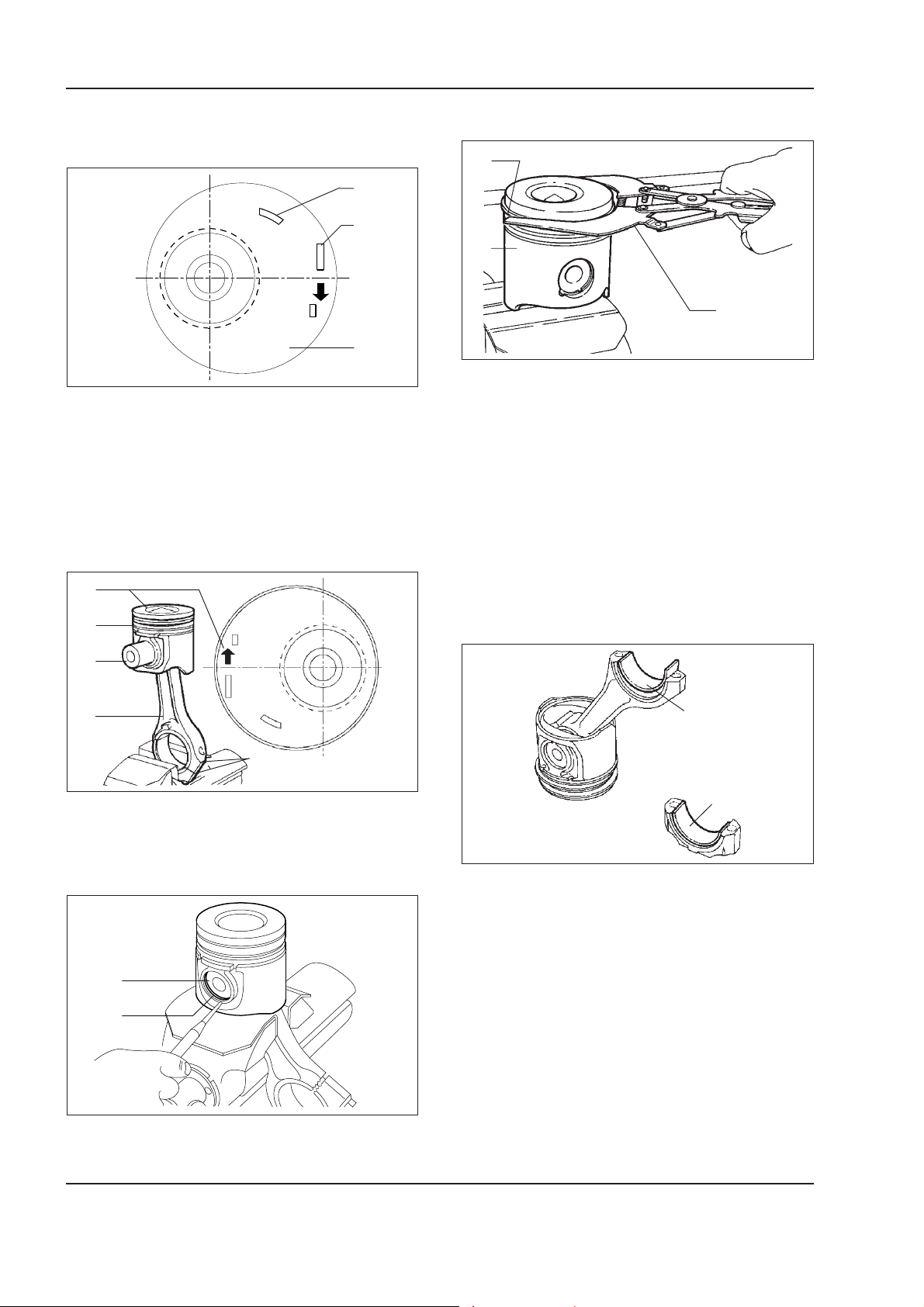
1 - 62 W130/W130TC
Copyright © New Holland
ENGINE
Installing the conrod-piston assembly
Conrods-bearing matching
1
2
FRONT
3
W110R0203
The following references are etched on the ceiling of
the piston:
1. Spare part number and number of the engineering
modification;
2. Date of manufacture
3. Wording indicating the mounting sign of the piston
into the cylinder sleeve. It must be directed toward
the front side of the cylinder block.
1
FRONT
2
Installing the piston rings
1
2
4
W110R0206
To install piston rings (1) on piston (2) use pliers
380000221.
The rings must be installed with the wording “TOP”
upward. Also arrange the ring gaps so that they offset
1200° among them.
Important –
Piston rings are supplied as spare parts
in the following dimensions:
- standard, identified by yellow paint;
- oversized 0.5 mm marked by yellow/green paint.
3
4
5
W110R0204
Connect piston (2) to conrod (4) with pin (3) so that
reference marking (1) for the installation of piston (2)
into the cylinder sleeve and digits (5) stamped on
conrod (4) are seen as indicated in the figure.
1
2
W110R0205
1
1
W110R0207
Install half bearings (1) both on the conrod and the
cap.
Important –
In the event the conrod bearing do not
need replacement, they must be reinstalled in the
identical order and sequence found at the disassembly.
Do not attempt any adjusting operation.
Insert circlips (2) securing pin (1).
Carefully read personal and machine SAFETY PRECAUTIONS (at the beginning of this manual)
Page 99
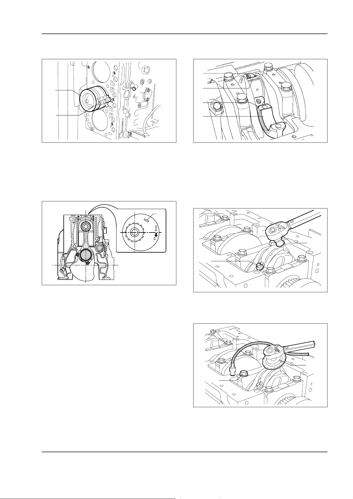
ENGINE
Copyright © New Holland
1 - 63W130/W130TC
Installation of conrod/piston assemblies into the
cylinder sleeves
1
2
W110R0208
Lubricate well the pistons, including the piston rings
and inside the cylinder sleeves.
Using band 380000220 (2) install conrod-piston assemblies (1) into the cylinder sleeves, checking that:
- the number of each conrod corresponds to the
matching number on the cap;
1
Measuring the mounting clearance of the conrod
journals
1
2
3
4
W110R0210
To measure the clearance, operate as follows:
- clean accurately the parts and eliminate all traces
of oil;
- place a piece of calibrated wire (2) on conrod journals (1);
- install conrod caps (3) with relevant half bearings
(4).
FRONT
W110R0209
Mounting diagram of conrod-piston assembly in
the tunnel
- the gaps of the piston rings are offset 120° among
them;
- the conrod-piston assemblies are all of the same
weight;
- the wording stamped on the top of the pistons is
directed toward the front side of the cylinder block
or the indent on the skirt of the piston corresponds
to the position of the oil nozzles.
2
1
W110R0211
- tighten screws (1) previously lubricated with engine
oil using torque wrench (2) to the prescribed torque.
1
2
W110R0212
- install tool 75301460 (1) on the socket wrench and
tighten screws (2) to the angle.
Carefully read personal and machine SAFETY PRECAUTIONS (at the beginning of this manual)
Page 100
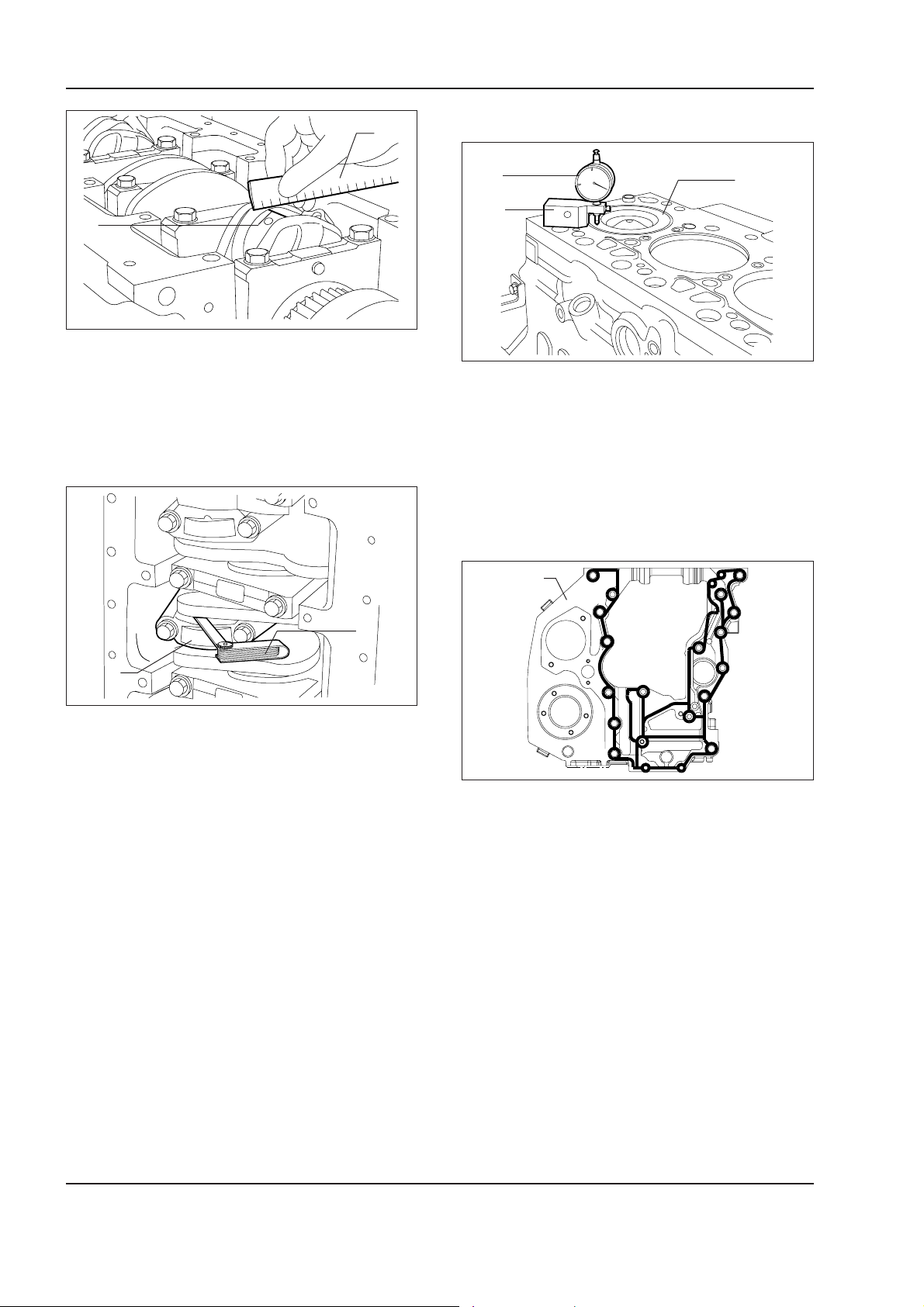
1 - 64 W130/W130TC
Copyright © New Holland
ENGINE
Checking the piston protrusion
2
1
W110R0213
- remove the cap and determine the clearance by
comparing the width of calibrated wire (1) with the
values of the scale provided on wrapping (2) containing the wire.
1
3
2
W110R0215
Once the installation of the conrod-piston assemblies
is completed, check the protrusion of pistons (3) at
T.D.C. with respect to the upper face of the cylinder
block, using dial gauge 380000228 (1) equipped with
base 380000364 (2).
It must be 0.28 to 0.52 mm.
Timing
Timing gear housing
1
2
1
W110R0214
If the clearance is not as prescribed, replace the half
bearings and repeat the check.
Once the prescribed clearance is obtained, lubricate
the conrod half bearings and install them permanently
tightening the screws securing the conrod caps, as
prescribed.
Important –
Prior to the final installation of the conrod
securing screws, check that their diameter measured
the centre of the threaded length is not smaller than
0.1 mm of the diameter measured about 10 mm from
the tip of the screws.
Check manually that conrod (1) slide axially on the
crankshaft and that the axial play measured with feeler
gauge (2) is 0.10 to 0.33 mm.
W110R0216
Diagram for the application of sealant Loctite 5999
Clean accurately timing gear housing (1) and the engine cylinder block.
The cleaning of the surface to be sealed is required
and indispensable to provide an effective sealing.
Apply sealant Loctite 5999 on the housing so as to
form a bead a few mm diameter. It must result uniform (no lumps) free from air bubbles, thin zones or
discontinuities.
Any imperfection must be corrected as soon as possible.
Avoid using material in excess to seal the joint.
Excessive sealant could escape on both sides of the
joint and clog lube passages.
After completing the application of the sealant, the
joints require an immediate installation (10 to 20 minutes).
Carefully read personal and machine SAFETY PRECAUTIONS (at the beginning of this manual)
 Loading...