

Page 1
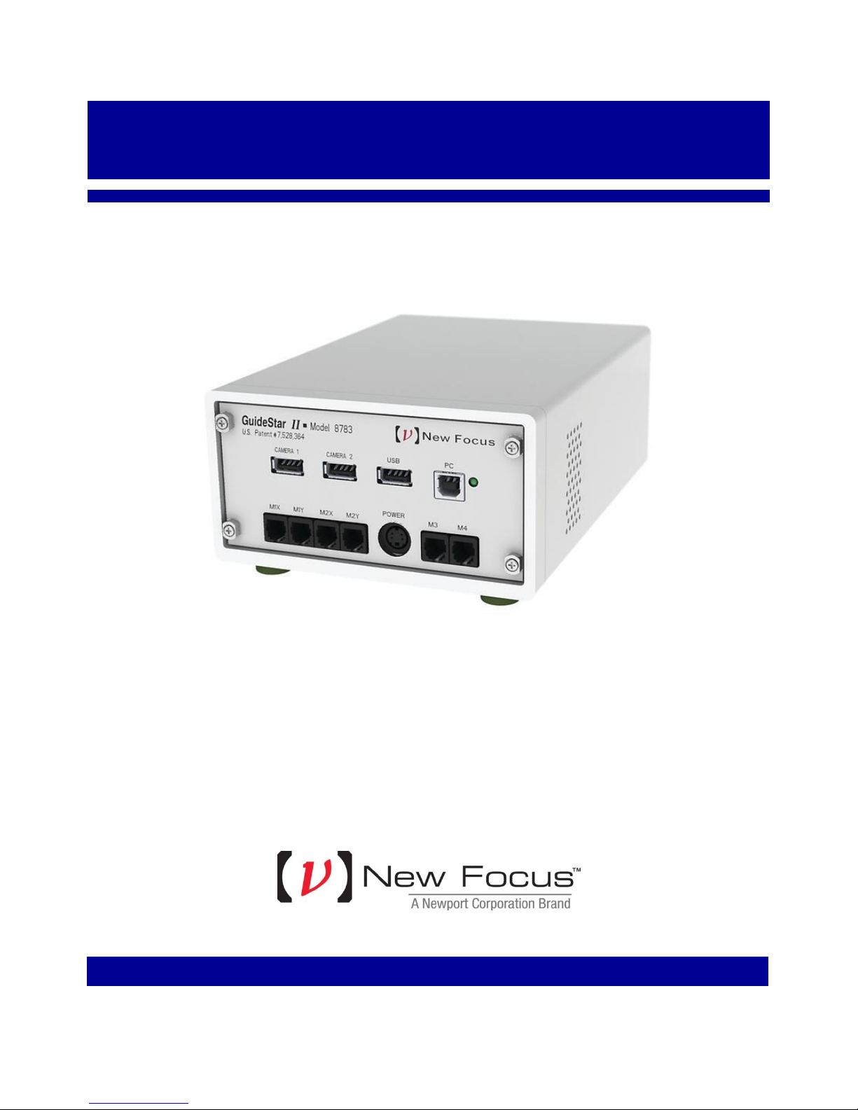
8783 GuideStar
TM
II Controller
User’s Manual
Page 2

EU Declaration of Conformity
We declare that the accompanying product, identified with the mark, complies with requirements of the
Electromagnetic Compatibility Directive,
2004/108/EC and the Low Voltage Directive 2006/95/EC.
Model Numbers: 8783
mark affixed: 2012
Type of Equipment: Electrical equipment for measurement, control and laboratory use in industrial locations.
Manufacturer:
Newport Corporation
1791 Deere
Irvine, CA 92606
Standards Applied:
Compliance was demonstrated to the following standards to the extent applicable:
BS EN61326-1: 2006 “Electrical equipment for measurement, control and laboratory use – EMC
requirements” for use in a controlled electromagnetic environment.
This equipment meets the CISPR 11:2009+A1 Class A Group 1 radiated and conducted emission limits.
BS EN 61010-1:2001, 2
and laboratory use”.
Avenue
nd
Edition “Safety requirements for electrical equipment for measurement, control
Dominique Devidal Quality Director Zone Industrielle
45340 Beaune-la-Rolande, France
Page 3

Warranty
New Focus warrants that this product will be free from defects in material and workmanship and will comply
with Newport’s published specifications
at the time of sale for a period of one year from date of shipment. If found to be defective during the warranty
period, the product will either be repaired or replaced at Newport's option.
To exercise this warranty, write or call your local Newport office or representative, or contact Newport
headquarters in Irvine, California. You
freight prepaid, to the indicated service facility. Repairs will be made and the instrument returned freight
prepaid. Repaired products are warranted for the remainder of the original warranty period or 90 days,
whichever first occurs.
Limitation of Warranty
The above warranties do not apply to products which have been repaired or modified without Newport’s written
approval, or products subjected
abuse, accident or negligence in use, storage, transportation or handling. This warranty also does not apply to
fuses, batteries, or damage from battery leakage.
THIS WARRANTY IS IN LIEU OF ALL OTHER WARRANTIES, EXPRESSED OR IMPLIED, INCLUDING ANY IMPLIED
WARRANTY OF MERCHANTABILITY OR FITNESS FOR A PARTICULAR USE.
NEW FOCUS SHALL NOT BE LIABLE FOR ANY INDIRECT, SPECIAL, OR CONSEQUENTIAL DAMAGES RESULTING
FROM THE PURCHASE OR USE OF ITS PRODUCTS.
First printing 2012
© 2012 by New Focus, Santa Clara, CA. All rights reserved. No part of this manual may be reproduced or copied
without the prior written approval of New Focus.
This manual has been provided for information only and product specifications are subject to change without
notice. Any change will be reflected in future printings.
New Focus
3635 Peterson Way
Santa Clara, CA, 95054
USA
Part No. 90038357 Rev A
will
to unusual
be given prompt assistance and return instructions. Send the product,
physical, thermal or electrical stress, improper installation, misuse,
Page 4

Confidentiality & Proprietary Rights
Reservation of Title
The New Focus programs and all materials furnished or produced in connection with them ("Related Materials")
contain trade secrets of New Focus and are for use only in the manner expressly permitted. New Focus claims
and reserves all rights and benefits afforded under law in the Programs provided by New Focus.
New Focus shall retain full ownership of Intellectual Property Rights in and to all development, process, align or
assembly technologies developed and other derivative work that may be developed by New Focus. Customer
shall not challenge, or cause any third party to challenge the rights of New Focus.
Preservation of Secrecy and Confidentiality and Restrictions to Access
Customer shall protect the New Focus Programs and Related Materials as trade secrets of New Focus, and shall
devote its best efforts to ensure that all its personnel protect the New Focus Programs as trade secrets of New
Focus. Customer shall not at any time disclose New Focus's trade secrets to
or employee that does not need (consistent with Customer's right of use hereunder) to obtain access to the New
Focus Programs and Related Materials. These restrictions shall not apply to information (1) generally known to
the public or obtainable from public sources; (2) readily apparent from the keyboard operations, visual display, or
output reports of the Programs; 3) previously in the possession of
Customer
acquired without reliance on the New Focus Programs; or (4) approved by New Focus for release without
restriction.
Trademarks
The New Focus logo and name are registered trademarks of Newport Corporation in Mexico, Israel, Singapore,
European Union, Taiwan, Hong Kong, China, Japan, Korea, Canada, Australia, and the United States.
Service Information
This section contains information regarding factory service for the source. The user should not attempt any
maintenance or service of the system or optional equipment beyond the procedures outlined in this manual. Any
problem that cannot be resolved should be referred to New Focus.
any other
person, firm, organization,
or subsequently developed or
Page 5

Technical Support Contacts
North America
Europe
New Focus
3635 Peterson Way, Santa Clara, CA 95054
Telephone: (866) 683-6287
Telephone: (408) 919-1500
Newport/MICRO-CONTROLE S.A.
Zone Industrielle
45340 Beaune la Rolande, FRANCE
Telephone: (33) 02 38 40 51 56
Asia
Newport Opto-Electronics Technologies 中国 上海市 爱都路 253号 第3号楼 3层 C部位, 邮编
200131
253 Aidu Road, Bld #3, Flr 3, Sec C, Shanghai 200131, China
Telephone: +86-21-5046 2300
Fax: +86-21-5046 2323
Newport Corporation Calling Procedure
If there are any defects in material or workmanship or a failure to meet
specifications, promptly notify Newport's Returns Department by calling 1-800-2226440 or by visiting our website at
www.newport.com/returns
within the warranty period to obtain a Return
Material Authorization Number (RMA#). Return the product to Newport Corporation, freight prepaid, clearly
marked with the RMA# and we will either repair or replace it at our discretion. Newport is not responsible for
damage occurring in transit and is not obligated to accept products returned
without an
RMA#.
E-mail: [email protected]
When calling Newport Corporation, please provide the customer care representative with the following
information:
Your Contact Information
Serial number or original order number
Description of problem (i.e., hardware or software)
To help our Technical Support Representatives diagnose your problem, please note the following
conditions:
Is the system used for manufacturing or research and development?
What was the state of the system right before the problem?
Have you seen this problem before? If so, how often?
Can the system continue to operate with this problem? Or is the system non- operational?
Can you identify anything that was different before this problem occurred?
Page 6

Table of Contents
1 Introduction ............................................... 3
1.1 Summary of GuideStarTM II System ..................................3
2 Safety Precautions ...................................... 4
2.1 Definitions and Symbols ....................................................4
2.1.1 General Warning or Caution .................................4
2.1.2 Electric Shock ........................................................4
2.1.3 European Union CE Mark .....................................5
2.1.4 Alternating Voltage Symbol ..................................5
2.1.5 USB .......................................................................5
2.1.6 Frame or Chassis ...................................................5
2.1.7 Waste Electrical and Electronic Equipment
(WEEE) .............................................................................6
2.1.8 Control of Hazardous Substances ..........................6
2.2 Warnings and Cautions ......................................................7
2.2.1 General Warnings ..................................................7
2.2.2 General Cautions ...................................................7
2.2.3 Summary of Warnings and Cautions .....................8
2.2.4 Additional power supply warnings ........................8
3 Getting Started ........................................... 9
4 System Operation ..................................... 11
3.1 Unpacking and Handling ...................................................9
3.2 Inspection for Damage ......................................................9
3.3 Parts List ............................................................................9
3.4 Choosing and Preparing a Suitable Work Surface ............9
3.5 Electrical Requirements ...................................................10
3.6 Computer requirements ...................................................10
4.1 System Overview .............................................................11
4.2 System set up ...................................................................12
4.3 Hardware set up ...............................................................12
4.3.1 Beam Pick-offs and Optical Power .....................12
1
Page 7

4.3.2 Optical Layout .....................................................12
4.4 Making Connections ........ Error! Bookmark not defined.
4.5 Software Operation ..........................................................15
4.5.1 System Set-up ......................................................15
4.5.2 Guide Star II Tab .................................................16
4.5.3 Beam Profiler Tab ...............................................21
4.5.4 Pointing Stability Tab ..........................................22
4.5.5 Stability Analysis .................................................22
4.5.6 Changing Scales on Images and Charts ...............23
4.5.7 Exiting the GuideStar II Application ...................24
5 Principles of Operation ............................. 25
5.1 GuideStar II Algorithm Theory .......................................25
5.2 Acquiring the Motion Matrix ..........................................26
6 Frequently Asked Questions ..................... 28
7 Maintenance and Service .......................... 31
7.1 Warranty ..........................................................................31
7.2 Technical Support ............................................................31
7.3 Obtaining Service ............................................................31
2
Page 8

1 Introduction
1.1 Summary of GuideStarTM II System
The GuideStar II laser stabilization system guarantees critical alignment of complex laser
systems by compensating beam pointing and position drift. The system is based on
Picomotor™ actuated mirrors which provide high-precision control with outstanding
intrinsic stability. Two miniature cameras provide complete position, pointing, and profile
information, while dedicated software implements a user-friendly, intelligent control
algorithm that keeps the beam’s four degrees of freedom precisely locked. The position
data is fed back to the mirror using our patented control algorithm (US Patent # 7,528,364
Optical Beam Steering and Sampling Apparatus and Method, 2009), the only technique
that completely corrects the laser beam position in both X and Y and the beam rotation
about both X and Y.
The system is anchored by the small GuideStar II Model 8783 controller which serves as a
USB hub for communication with the cameras and also serves as a multiplexed Picomotor
driver to generate drive signals for the four motors.
The controller connects to the user’s host computer via USB. And the host computer runs
the GuideStar II software which is user-friendly and conveniently permits full beam
profiles and beam position data which can be tracked, stored, and analyzed. An easy set-up
menu guides new users through the installation. Simple settings menus allow complete
control of a wide range of camera and beam stabilization parameters including: 1000:1
dynamic camera exposure time, loop gain to optimize performance of the control loop, and
complete control of target size and location for each camera.
Designed for accuracy, reliability, and ease-of-use, the GuideStar™ II System is the answer
to laser beam drift correction for the most demanding laser applications.
3
Page 9

2 Safety Precautions
2.1 Definitions and Symbols
The following terms and symbols are used in this documentation and appear on the
Model 8783 GuideStar II controller where safety-related issues occur.
2.1.1 General Warning or Caution
Figure 1. General Warning or Caution Symbol
The Exclamation Symbol in the figure above appears on the product and in
Warning and Caution tables throughout this document. This symbol designates
that documentation needs to be consulted to determine the nature of a potential
hazard, and any actions that have to be taken.
2.1.2 Electric Shock
Figure 2. Electrical Shock Symbol
The Electrical Shock Symbol in the figure above appears throughout this manual.
This symbol indicates a hazard arising from dangerous voltage. Any mishandling
could result in irreparable damage to the equipment, and personal injury or death.
4
Page 10
2.1.3 European Union CE Mark
Figure 3. CE Mark
The presence of the CE Mark on Newport Corporation equipment means that this
instrument has been designed, tested and certified compliant to all applicable
European Union (CE) regulations and recommendations.
2.1.4 Alternating Voltage Symbol
Figure 4. Alternating Voltage Symbol
This international symbol implies an alternating voltage or current.
2.1.5 USB
Figure 5. USB Symbol
The symbol in the figure above identifies the USB connector location on the
Model 8783 Controller.
2.1.6 Frame or Chassis
Figure 6. Frame or Chassis Terminal Symbol
The symbol in the figure above appears on the Model 8783 Controller. This
symbol identifies the frame or chassis terminal.
5
Page 11

2.1.7 Waste Electrical and Electronic Equipment (WEEE)
Figure 7. WEEE Directive Symbol
This symbol on the product or on its packaging indicates that this product must not
be disposed with regular waste. Instead, it is the user responsibility to dispose of
waste equipment according to the local laws. The separate collection and
recycling of the waste equipment at the time of disposal will help to conserve
natural resources and ensure that it is recycled in a manner that protects human
health and the environment. For information about where the user can drop off the
waste equipment for recycling, please contact your local Newport Corporation
representative.
2.1.8 Control of Hazardous Substances
Figure 8. RoHS Compliant Symbol
This label indicates the products comply with the EU Directive 2002/95/EC that
restricts the content of six hazardous chemicals.
6
Page 12

2.2 Warnings and Cautions
2.2.1 General Warnings
Observe these general warnings when operating or servicing this equipment:
Heed all warnings on the unit and in the operating instructions.
Do not use this equipment in or near water.
This equipment is grounded through the grounding conductor of the power
cord.
Route power cords and other cables so that they are not likely to be
damaged.
Disconnect power before cleaning the equipment. Do not use liquid or
aerosol cleaners; use only a damp lint-free cloth.
Lockout all electrical power sources before servicing the equipment.
To avoid fire hazard, use only the specified fuse(s) with the correct type
number, voltage and current ratings as referenced in the appropriate
locations in the service instructions or on the equipment. Only qualified
service personnel should replace fuses.
To avoid explosion, do not operate this equipment in an explosive
atmosphere.
Qualified service personnel should perform safety checks after any service.
2.2.2 General Cautions
Observe these cautions when operating this equipment:
If this equipment is used in a manner not specified in this manual, the
protection provided by this equipment may be impaired.
Do not block ventilation openings.
Do not position this product in such a manner that would make it difficult
to disconnect the power cord.
Use only the specified replacement parts.
Follow precautions for static sensitive devices when handling this
equipment.
This product should only be powered as described in the manual.
There are no user-serviceable parts inside the Model 8783 GuideStar II
controller.
Adhere to good laser safety practices when using this equipment.
7
Page 13
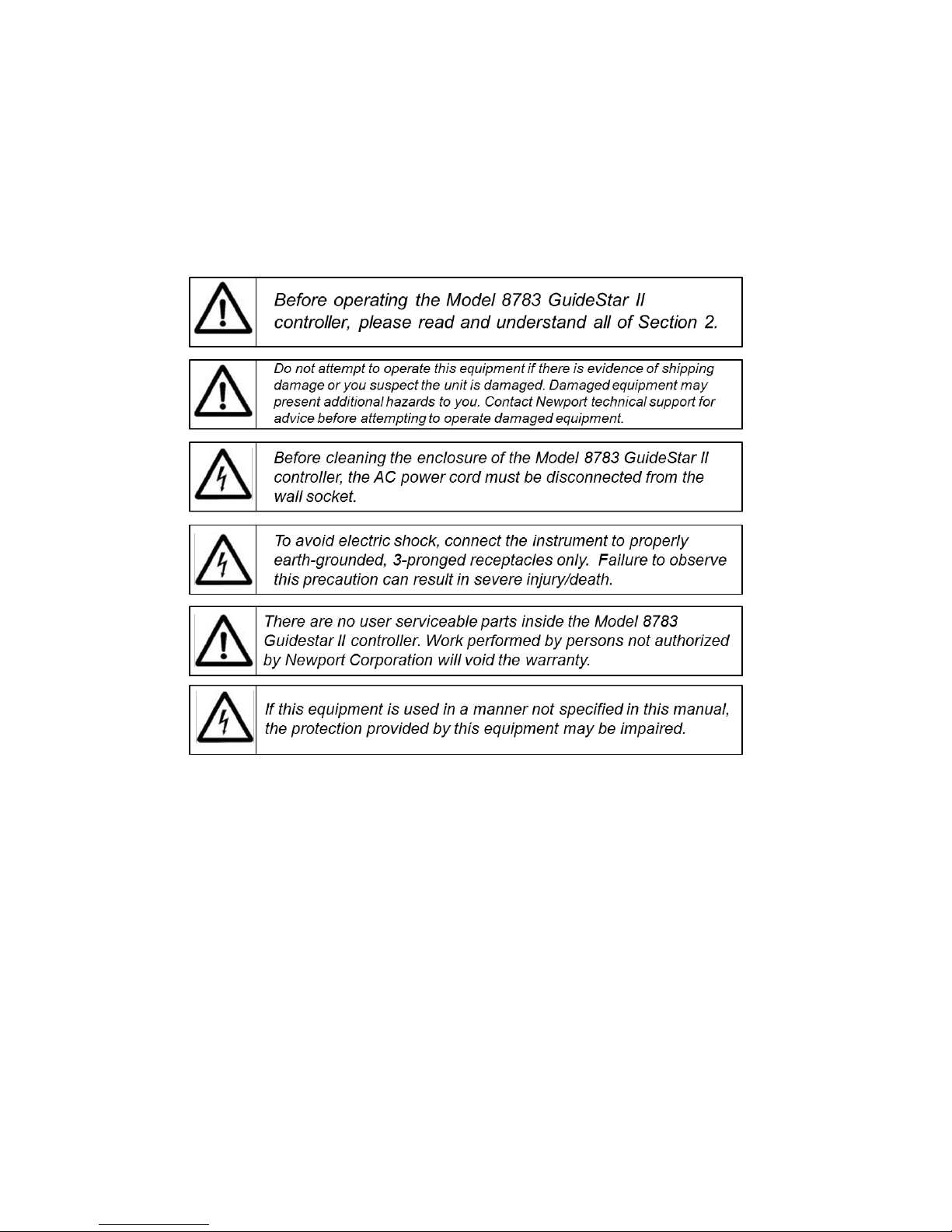
2.2.3 Summary of Warnings and Cautions
The following are definitions of the Warnings, Cautions and Notes that are used
throughout this manual to call your attention to important information regarding
your safety, the safety and preservation of your equipment, or an important tip.
following general warning and cautions are applicable to this instrument:
The
2.2.4 Additional power supply warnings
This product is equipped with a three prong plug. For proper operation and your
protection this plug should not be modified and must be plugged directly into a
properly grounded three prong receptacle.
This product if not provided with a power switch. Do not block access to the
power connector in case emergency shutdown is required.
Voltages of up to 130V are accessible inside the driver chassis, mounts, and
Picomotors. Although protection circuits are included, do not operate the units
with the driver or mount covers removed. If the wire of a mount of Picomotor is
frayed, discontinue use and return item for repair.
8
Page 14

3 Getting Started
3.1 Unpacking and Handling
It is recommended that the Model 8783 GuideStar II controller be unpacked
carefully in a lab environment; small parts are included with the instrument.
Inspect the box carefully for loose parts. You are advised to save the packaging
material in case you need to ship your equipment in the future.
3.2 Inspection for Damage
The Model 8783 GuideStar II controller is carefully packaged at the factory to
minimize the possibility of damage during shipping. Inspect the box for external
signs of damage or mishandling. Inspect the contents for damage. If there is
visible damage to the instrument upon receipt, inform the shipping company and
New Focus immediately. Carefully open the box and save the shipping material
for later use.
3.3 Parts List
The following is a list of parts included with the Model 8783 GuideStar II
controller:
8783 GuideStar II controller
CD with Software Drivers and Utilities, User’s Manual, Start Up Guide.
Power adaptor and power cord.
USB cable for connecting to computer. If you are missing any parts or
have questions about the parts you have received, please contact New
Focus.
3.4 Choosing and Preparing a Suitable Work Surface
The GuideStar II may be placed on any reasonably firm table or bench during
operation.
9
Page 15

3.5 Electrical Requirements
Before attempting to power up the unit for the first time, the following precautions
must be followed:
Have a qualified electrician verify the wall socket that will be used is
properly polarized and properly grounded.
Provide adequate distance between the Models 8783 GuideStar II
Controller and adjacent walls for ventilation purposes. Do not let any
other equipment blow hot air towards the unit.
3.6 Computer requirements
Software:
Windows 7 – 32 bit, 64 bit
Windows XP – 32 bit only
Processor:
AMD DUAL CORE, AMD QUAD CORE
Intel Pentium Dual Core, Intel Pentium Quad Core, Intel Pentium Core ( i3 , i5 ,
i7 )
RAM 4GB minimum
HDD 160GB minimum
DVD player
Screen resolution: 1920x1080 minimum
Monitor: HD 1920x1080 resolution minimum
10
Page 16

4 System Operation
4.1 System Overview
GuideStar II is a closed-loop beam stabilization system in which cameras measure
beam position at two points along the beam path, while two preceding mirrors
actuated by Picomotors keep these two positions steady. The centroid information
from each camera is processed and fed back to the X and Y control of each mirror
mount in a generalized manner via a 16-element array (called the “Motion
Matrix”). This approach accounts for all direct- and cross- couplings between the
centroid position and the mirror axes, allowing for nominally perfect control of
the beam with arbitrary optical systems. An automated calibration routine
provides the needed stimulus to each motor to determine the Motion Matrix
values.
The control loop functions by making adjustments to the mirrors only when the
beam has drifted out of a user-defined target area on one or both of the camera
sensors. When this happens, the beam is moved back inside the target area on
both sensors. To provide control over how often the beam is moved, an Inner
Target and an Outer Target are defined for the sensors. When the beam drifts
outside of one or both of the Outer Targets, it is moved back inside the smaller
Inner Target on both sensors. Then it is not moved again until it drifts outside of
one or both of the Outer Targets. Suitable choice of the target sizes can result in
relatively infrequent motor activity to maintain beam pointing and position within
a user-defined range. Thus the beam can be left largely unperturbed.
Dynamic performance of the control loop is determined by several things. Two
settings in particular allow one to control the dynamic behavior – the Loop Gain
and Frames to Average Over. These provide the flexibility to optimize the loop
response.
The Model 8784 cameras are shipped with an installed lens and neutral density
filters. The lens provides beam size reduction, allowing ~1-cm beams to be used
with the 5.3 mm sensors. The cameras’ OD-1,-2, and -4 filters provide coarse
optical attenuation, while the exposure time setting of the cameras allows for fine
exposure control over a range of roughly 1 – 1000 ms.
In addition, operation with low (<500 Hz) repetition rate lasers is possible with
the Model 8783-T Trigger Kit.
11
Page 17
300 400 500 600 700 800 900 1000 1100 1200 1300
Wavelength (nm)
1 W
1 mW
1mW
1 nW
4.2 System set up
The Quick Start Guide contains information to set up the system. Please refer to
the quick start guide to install software, configure the cameras, and connect
components with the included cables. Additional details on hardware set up and
software operation are found below.
4.3 Hardware set up
4.3.1 Beam Pick-offs and Optical Power
The power required for the cameras is low, so it is recommend that the leakage
through HR mirrors with polished backsides be used as beam “pickoffs.” Other
options include reflections off AR surfaces or uncoated beam-splitters in the
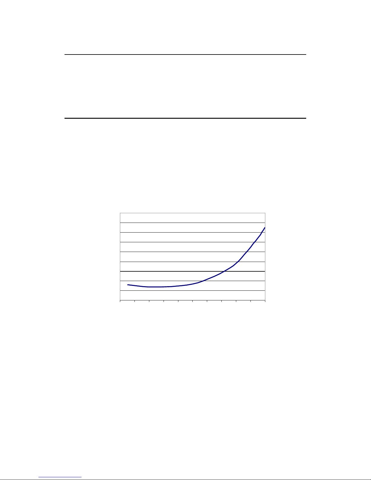
beam. The saturation power of the cameras is shown in Figure 3.2a. If beam size
and exposure time are accounted for, this figure can be used to choose appropriate
pick-offs and attenuation for the beam. Fine tuning of power is accomplished via
the exposure time so as to maximize dynamic range.
Figure 9. Approximate saturation power of the cameras with a 10-ms
exposure time and a 2-mm beam diameter. Exposure time can range from 1 to
980 ms.
4.3.2 Optical Layout
The physical layout of the two cameras and two motorized mirror mounts may
affect the performance of the GuideStar II System. As a general guideline, the
separation between the mirrors and the separation between the cameras should be
large and comparable, while the separation between Mirror 2 and Camera 1
should be much shorter, as short as conveniently possible (see Figure 3.2b).
12
Page 18
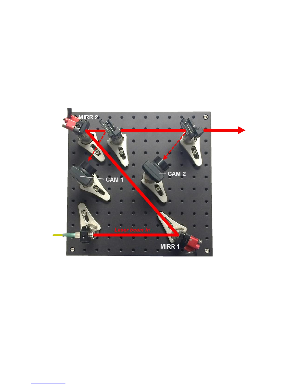
Typical values might be 50 cm between mirrors, 50 cm between cameras, and 10
cm between Mirror 2 and Camera 1.
Note that the system can tolerate a wide range of deviation from these guidelines.
In general, however, a larger spacing between cameras will allow for tighter
pointing control, since the maximum pointing drift under closed-loop operation
will be determined by the ratio of the Target size to the separation between the
cameras. For example, for a 30-μm Target, pointing drift will be limited to 60
μrad for a 0.5-m separation and 30 μrad for a 1-m separation.
Figure 10. Example physical layout of mirrors and cameras for GuideStar II
system.
To optimize performance, Camera 2 can be positioned so as to image a plane
equivalent to the users working plane. This can be accomplished by setting the
distance between the second pickoff and the working plane comparable to the
distance between the second pickoff and Camera 2’s object plane, which is about
4 cm in front of the lens. By doing this the beam position data and image shown
by the GuideStar II software are essentially those of the working plane.
13
Page 19
4.3.3 Connecting Hardware to the Controller
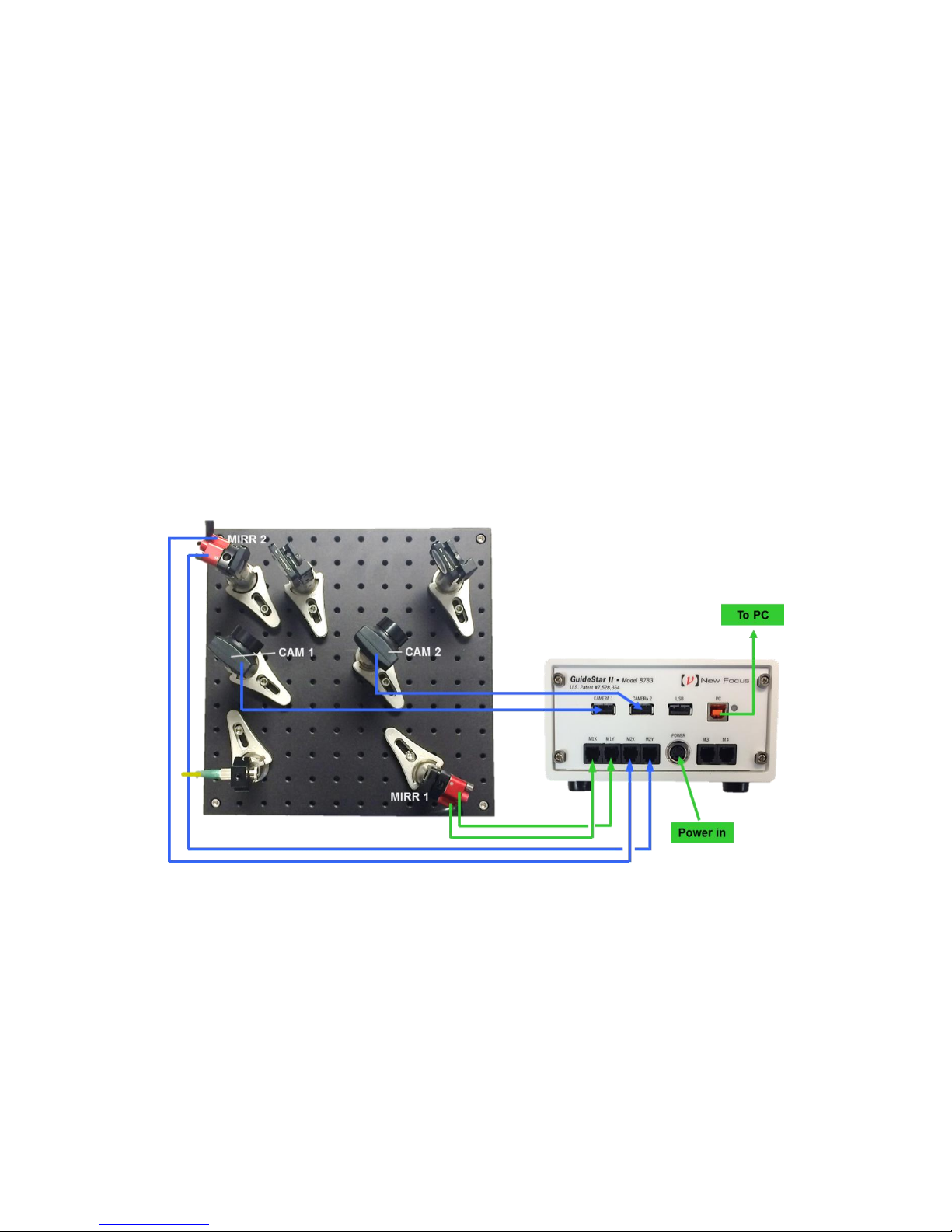
Figure 11 shows how to connect the mirrors and cameras to the GuideStar II
Controller. These connections should all be made prior to launching the
GuideStar II application. Failure to make these connections prior to opening the
application may lead to an error message. If this occurs, close the GuideStar II
application, make the necessary connections, and re-open the application.
Ensure that the x-axis and y-axis motor of Mirror 1 is connected to M1X and
M1Y, respectively. Similarly, the x-axis and y-axis motors of Mirror 2 should be
connected to M2X and M2Y. This is a common source of error that can be
avoided.
The first Camera along the beamline is Camera 1 and it should be cabled to the
Camera 1 USB port on the controller. Similarly, Camera 2 is connected to the
Cameras 2 USB port on the controller.
Figure 11. Layout of connections from Mirror Mounts and Cameras to GuideStar
II controller
14
Page 20
4.4 Software Operation
4.4.1 System Set-up
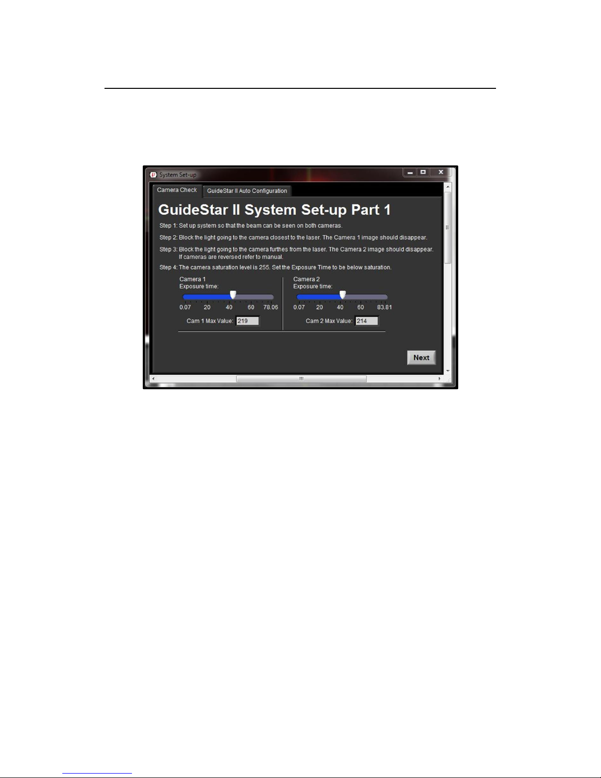
The first time the application is launched it will automatically open the System
Set-up window and display the Camera Check tab:
Figure 12. System Set-up window available through GuideStar II Tab.
This window cannot be closed until steps 1 - 4 are completed. If blocking the
beams to the Camera 1 causes the Camera 2 image to disappear in the GuideStar
II display (or vise-versa), then the camera IDs should be swapped. (For
instructions on how to do this, see Section 6: Frequently Asked Questions.)
Now, click “Next” or click on the “GuideStar II Auto Configuration” tab:
15
Page 21
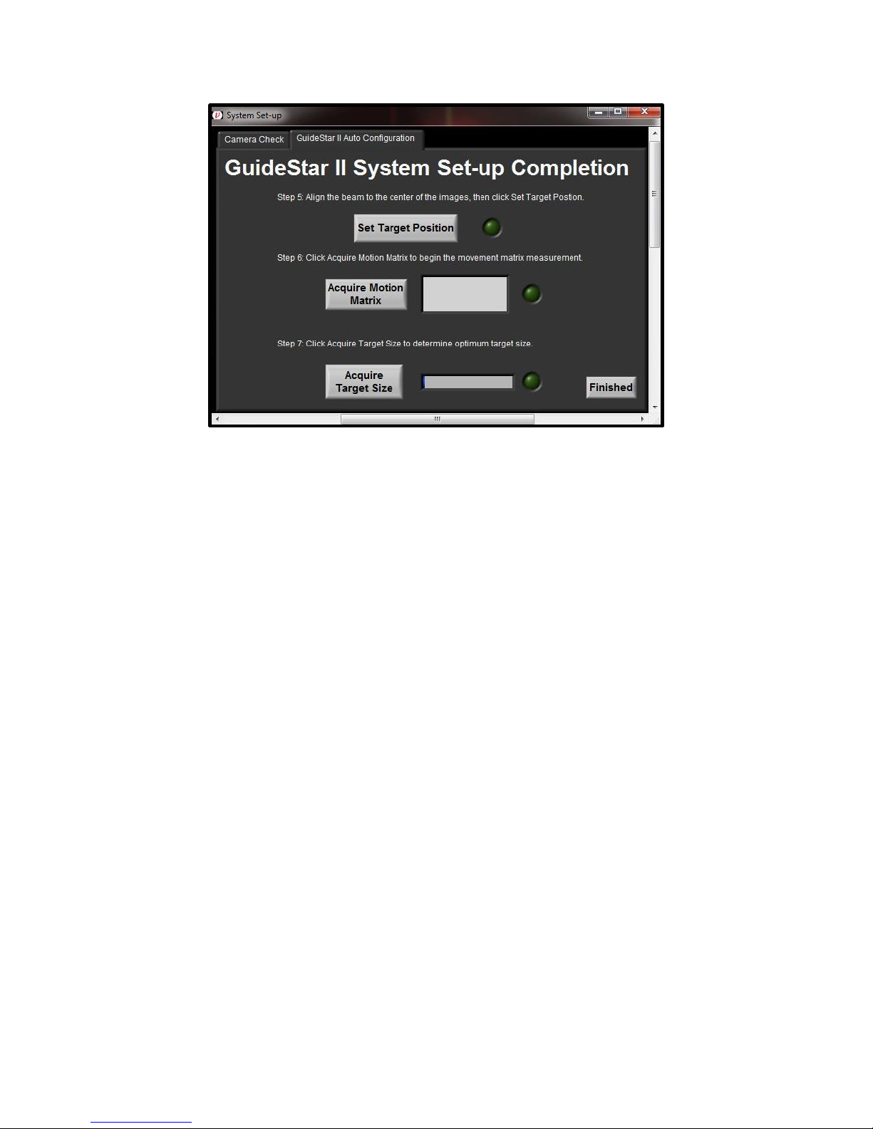
Figure 13. Example physical layout of mirrors and cameras for GuideStar II
system.
In Step 5, you will set the target position. To do this, click the Set Target Position
button. This will ensure that the system will return to the original alignment after
the motion acquisition. Once the Target Position has been set, the green light next
to the Set Target Position button will be lit. The target position can easily be reset later if additional adjustment is desired. This is done by re-clicking the Set
Target Position button.
In Step 6, you acquire the Motion Matrix. Click the “Acquire Motion Matrix”
button. Over the next several minutes, the system will move each motor (X1, Y1,
X2, Y2) by pre-defined amounts in the positive and negative directions and stop
once it has gathered enough information or the beam has moved to the edge of the
optical aperture. Once the Motion Matrix has been acquired, the green light next
to the Acquire Motion Matrix button will be lit.
In Step 7, you acquire the target size. Click the “Acquire Target Size” button and
the software will analyze the noise of the beam to determine a recommended
target size for the motion settings. (The recommended target size can be changed
later if desired.) Click the Finished button to close the System Set-up window and
save the settings via the subsequent pop-up window.
4.4.2 Guide Star II Tab
The first tab of the GuideStar II program is labeled Guide Star II. On this tab is
each camera’s image; a display of the target and centroid locations for each
16
Page 22
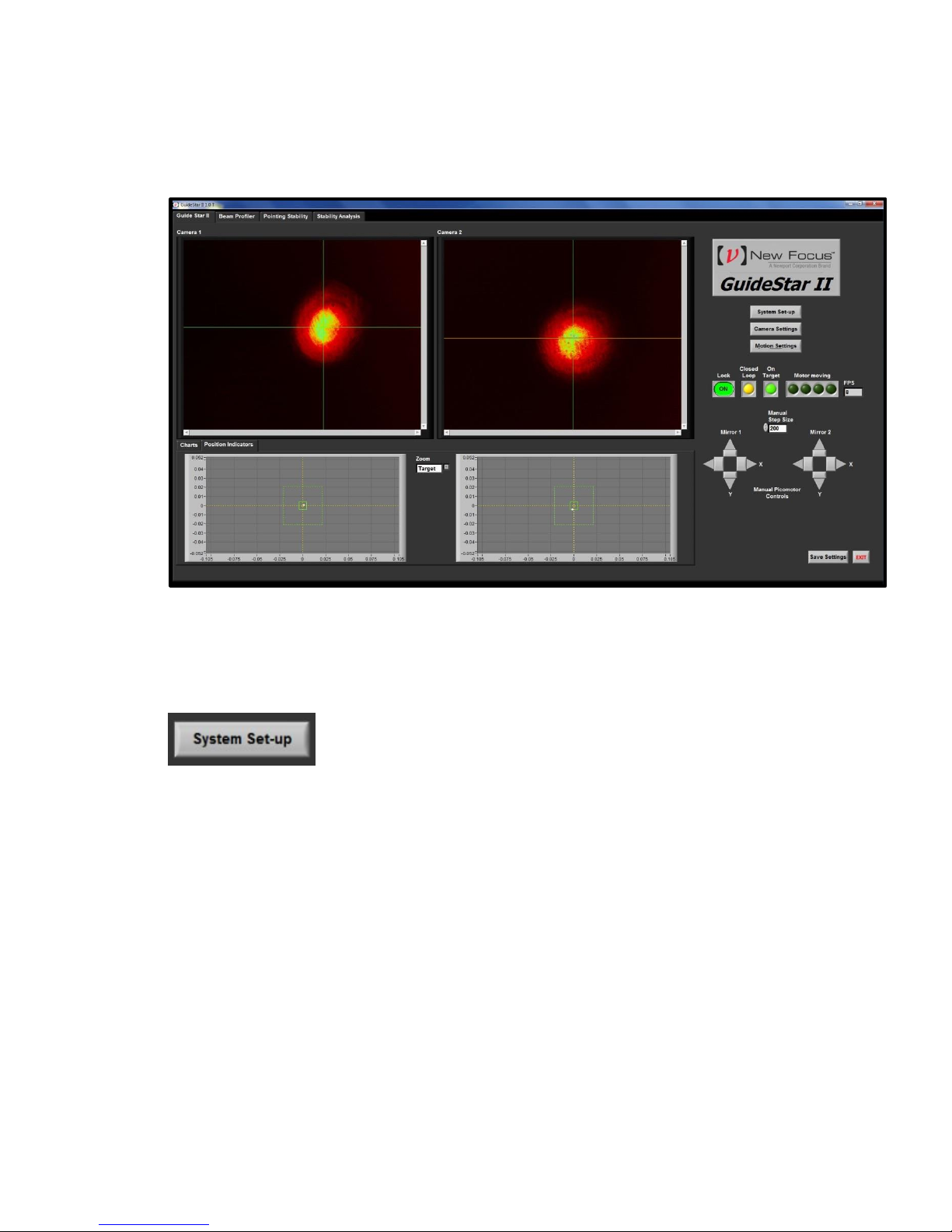
camera; buttons for System Set-up, Camera Settings, and Motion Settings;
indicator lights and a Lock On/Off button; and two controls for manually
activating the motors:
Figure 14. Screenshot of information and buttons available under GuideStar
II Tab.
This button will turn off Lock and open the same System Set-up described
Section 4.4.1. System set-up can be repeated at any time. To close the
window, click on the Finished button on the GuideStar II Auto
Configuration tab. A pop-up window will open in which you can save
changes to the System Set-up.
17
Page 23
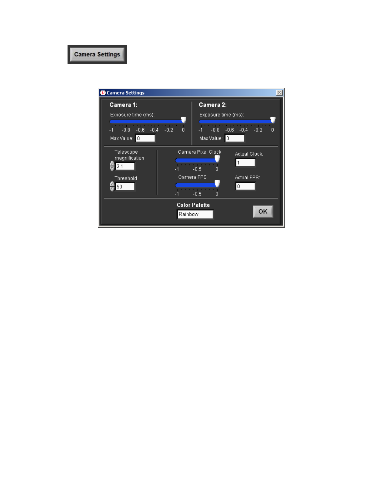
This button will turn off Lock and open the Camera Settings window:
Figure 15. Camera Settings Window available through the GuideStar II Tab.
o Exposure Times should be set so that Max Value for each camera is
below 255. The sensors saturate at Max Value = 255.
o Pixel Clock: At high Pixel Clock values (>20-25), a Pixel Clock Error
may occur. The default value can be used in most cases.
o FPS (frames per second) A lower FPS will slow loop response but will
permit longer Exposure Times. The default value can be used in most
cases.
o Telescope magnification The default value should be used in most cases.
This number is used to convert positions on the camera sensors to
positions of the incident beam. Values of beam position and width
reported on all tabs scale with this number. The default is the nominal
value at the center of the image. Distortion is present towards the image
edges.
o Threshold Pixel values below the Threshold will be ignored in centroid
calculations. This is used to reduce effects of ambient or stray light.
To close the Camera Settings window, click on the OK button.
18
Page 24
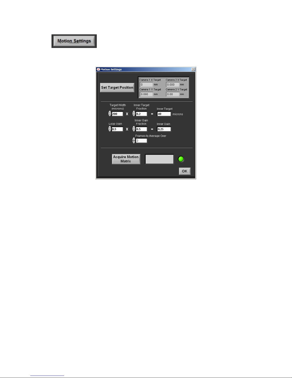
This button will turn off Lock and open the Motion Settings window:
Figure 16. Motion Settings Window available through the GuideStar II Tab.
o Set Target Position This button will reset the target centers to the current
beam locations. This can be executed without the need to re-acquire the
Motion Matrix.
o Target Width is the size of the Outer Target.
o Inner Target Fraction Target Width multiplied by the Inner Target
Fraction gives the Inner Target size.
o Loop Gain When position Lock is on, and the beam moves outside the
outer target, the motors are commanded to move the beam back to the
Inner Target. The distance to the center of the Inner Target, scaled by the
Loop Gain, is the size of the step taken. This parameter will influence the
dynamic response of the control loop. It is recommended that one start
with the default value and adjust it to achieve a well-behaved (no ringing,
relatively fast) return of the beam to the Inner Target. A higher value will
increase the speed of the loop response but may lead to ringing or erratic
behavior. A lower value will give a well-behaved response but may make
the response to slow. Typically, Loop Gain is set such that the beams are
brought back to their Inner Targets within 2-5 seconds.
o Inner Gain Fraction This value will scale the loop gain once the beam is
within the Outer Target.
19
Page 25

o Frames to Average Over Determines the level of running averaging for
centroid locations used in the control algorithm. As with Loop Gain, it is
recommended that one start with the default value and adjust it to achieve
a well-behaved (no ringing, relatively fast) return of the beam to the Inner
Target. A higher value may slow loop response but may improve
performance overall.
o Acquire Motion Matrix Click this button to initiate the routine to acquire
the Motion Matrix. This only needs to be done during the initial system set
up. This routine can take several minutes.
Figure 17. Example physical layout of mirrors and cameras for GuideStar II
system.
o Manual Picomotor Controls The pair of four arrows with buttons
provide manual control of the Picomotors. These can be used to manually
position the beams during set up, and also to test the response of the
control loop. By pressing a button while Lock is on, the dynamic
performance of the loop can be evaluated. Set the Manual Step Size such
that clicking an arrow will take the beams out of the Outer Target area.
Ideally the beams will return to their targets in a relatively fast and wellbehaved manner. This is a useful test when adjusting the Motion Settings
(see below) to optimize loop performance.
To close the Motion Settings window, click on the OK button.
20
Page 26
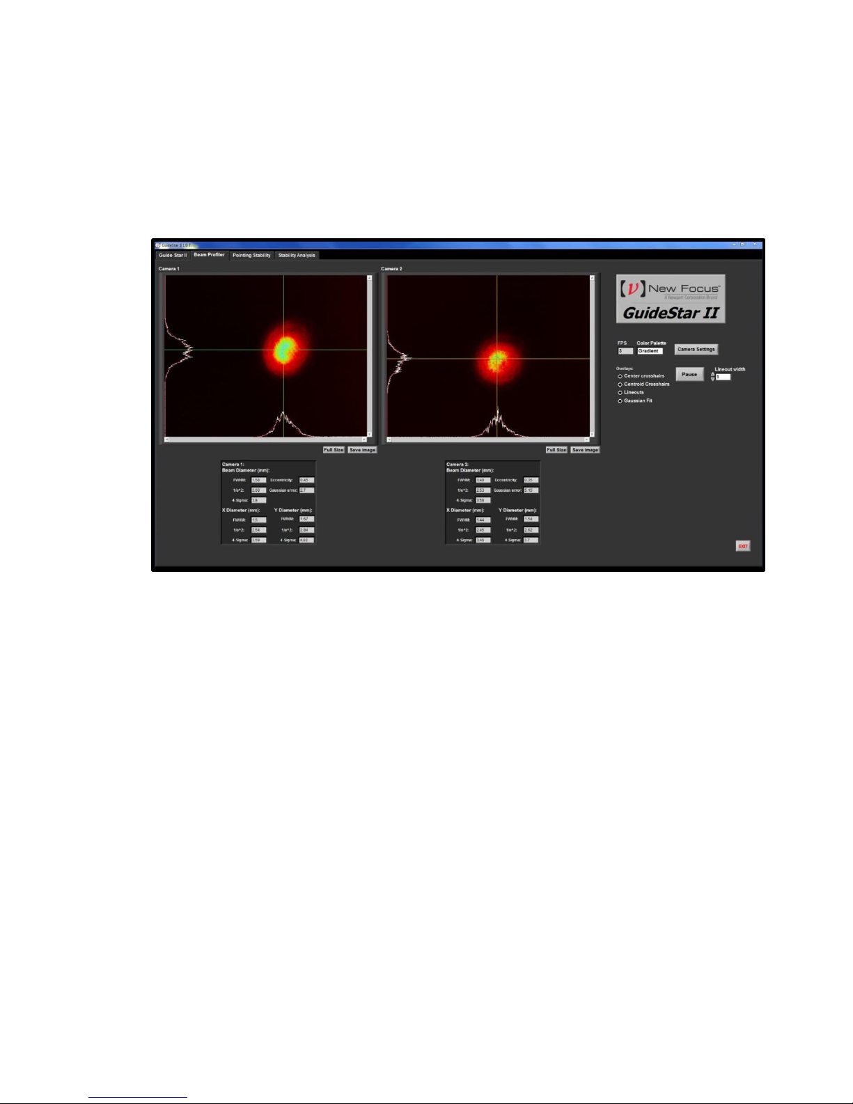
4.4.3 Beam Profiler Tab
Under the Beam Profiler tab basic beam profiling information is displayed. Also
available is the Camera Settings button and a Pause button. The Full Size button
under each image will enlarge the image. This can be reversed by hitting Esc on
the keyboard. The Save Image button allows one to save a .JPG image to disk.
Figure 18. Example beam profile information available under Beam Profiler
Tab.
21
Page 27
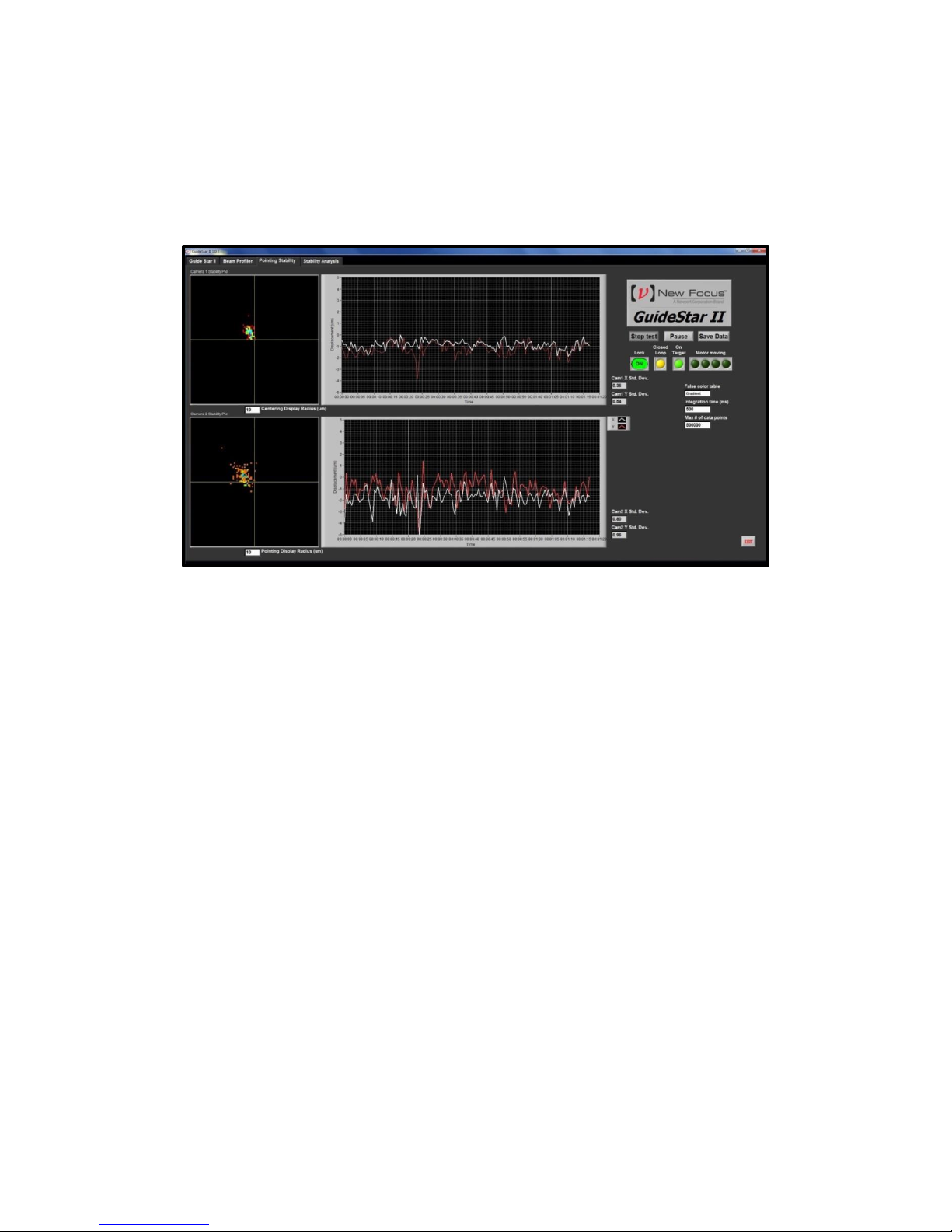
4.4.4 Pointing Stability Tab
The Pointing Stability tab shows automatically generated graphs of the beam
position data being gathered by the cameras. You can customize how much data is
taken and save it to a .txt file.
Figure 19. Example automatically generated graphs of beam position data
found in Pointing Stability Tab
4.4.5 Stability Analysis
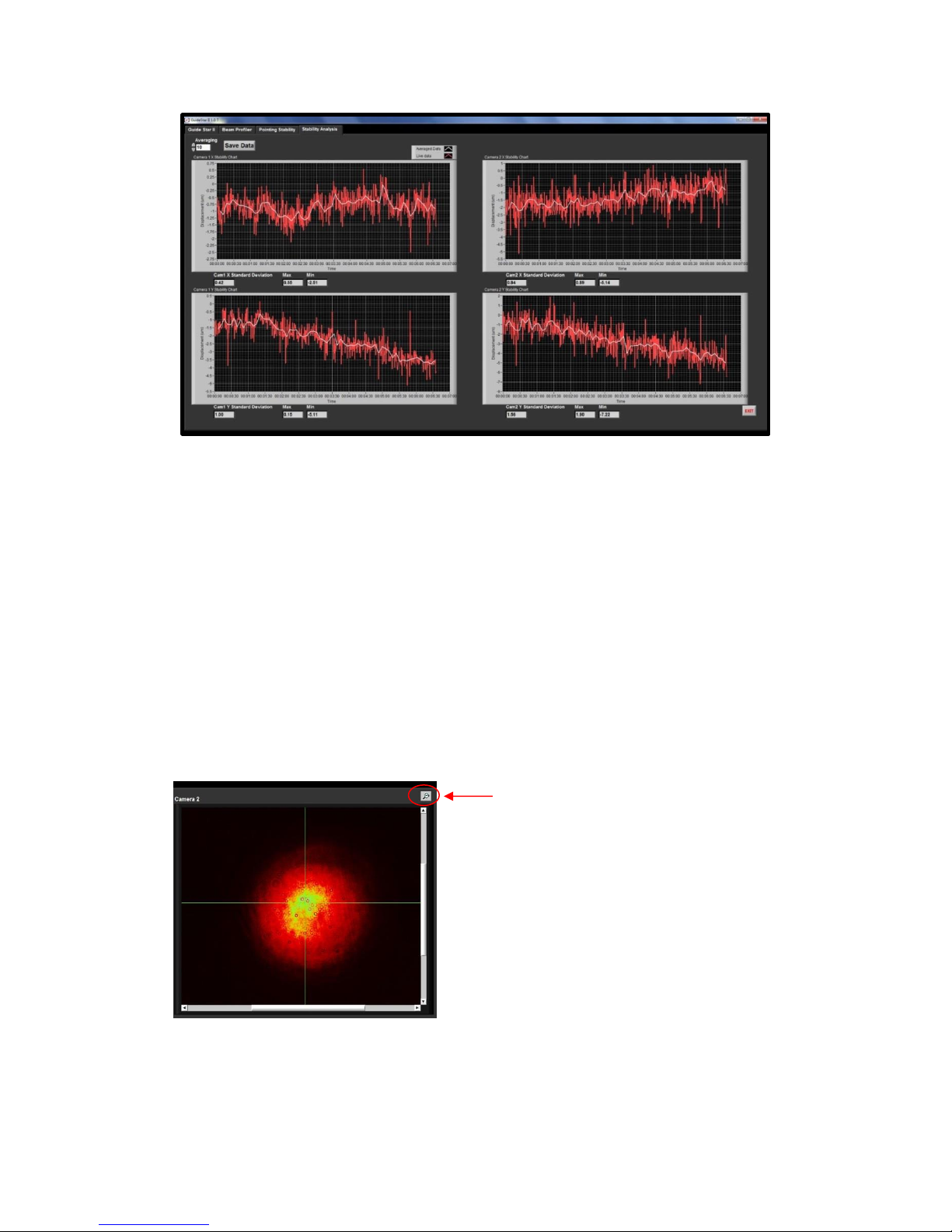
The Stability Analysis tab contains the individual data plots for X1, Y1, X2, Y2.
This is the raw data as well as user-defined averaged data, and it is controlled by
the Start test and Pause buttons on the Pointing Stability Tab. This data can be
saved to a .txt file using the Save Data button.
22
Page 28
click to reset the zoom
Figure 20. Example of individual plots of raw stability data collected for X1,
Y1, X2, Y2 available in Stability Analysis tab
4.4.6 Changing Scales on Images and Charts
To change the scale of a chart: Autoscaling of the X and Y axes can be turned
on and off by right-clicking on the graph or axis. For manual scaling, clicking on
the maximum or minimum data label on an axis allows one to change its value.
To change the scale of a camera image: Move the mouse pointer over an image
to enable the magnifying glass. Click to zoom in around the pointer location, or
shift-click to zoom out. When zoomed in or out, an icon will appear in the upper
right corner. Clicking this will reset the zoom so that the full sensor area is shown.
Figure 21. Example physical layout of mirrors and cameras for GuideStar II
system.
23
Page 29

4.4.7 Exiting the GuideStar II Application
To exit the GuideStar II application, click on the Exit button in the lower right
corner. Then, the GuideStar II window can be closed by either clicking on the
close box in the upper right corner of the window, or by going to File Exit in
the upper left corner.
24
Page 30
CAM1X
CAM1Y
CAM2X
CAM2Y
MM1X
MM1Y
MM2X
MM2Y
A11A12A13A
14
A21A22A23A
24
A31A32A33A
34
A41A42A43A
44
Movement Matrix A
CAM1X
CAM1Y
CAM2X
CAM2Y
MM1X
MM1Y
MM2X
MM2Y
A
MM1X
MM1Y
MM2X
MM2Y
CAM1X
CAM1Y
CAM2X
CAM2Y
A
-1
CAM1X
CAM1Y
CAM2X
CAM2Y
MM1X
MM1Y
MM2X
MM2Y
A11A12A13A
14
A21A22A23A
24
A31A32A33A
34
A41A42A43A
44
Movement Matrix A
CAM1X
CAM1Y
CAM2X
CAM2Y
MM1X
MM1Y
MM2X
MM2Y
A
MM1X
MM1Y
MM2X
MM2Y
MM1X
MM1Y
MM2X
MM2Y
CAM1X
CAM1Y
CAM2X
CAM2Y
CAM1X
CAM1Y
CAM2X
CAM2Y
A
-1
5 Principles of Operation
5.1 GuideStar II Algorithm Theory
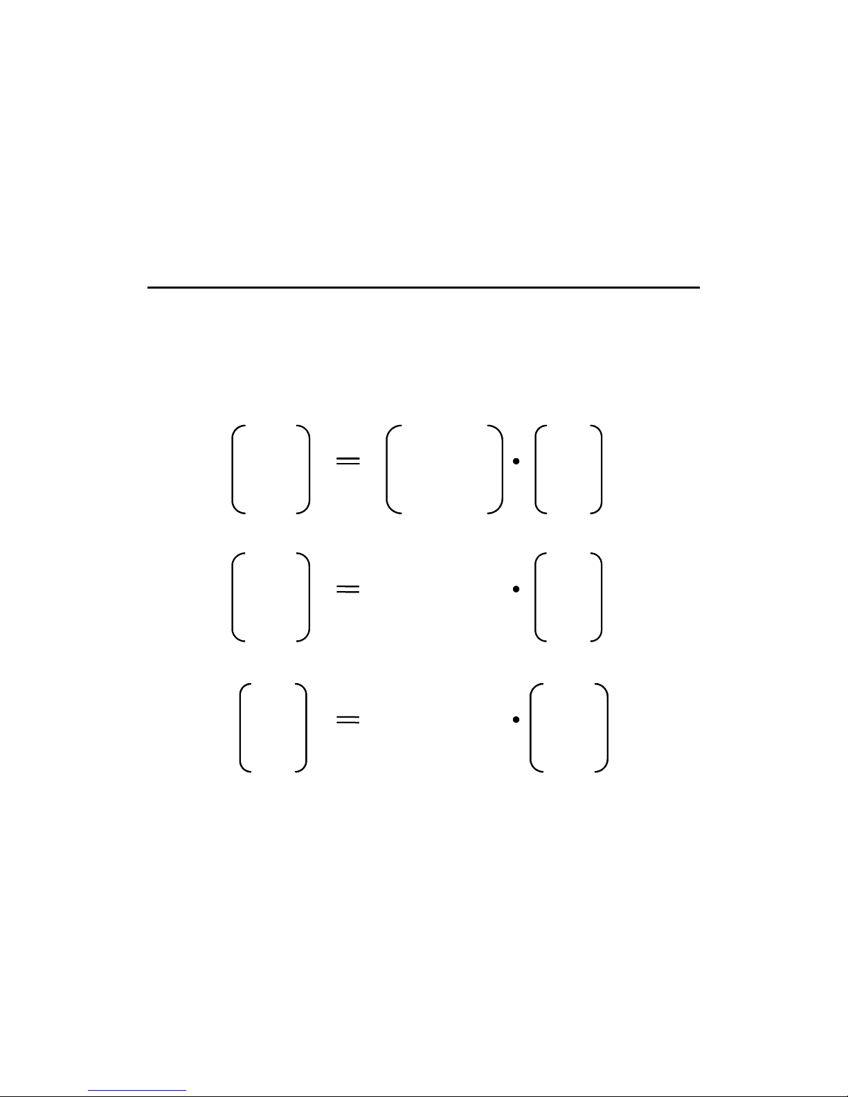
The control algorithm moves each Motor one at a time in accordance to the Lock
Equation derived from the Inverse Movement Matrix, the difference between the
current beam positions and the target beam positions and the gain coefficient.
Above is the equation that would drive the beam all the way to the target in a
single step. However, because of the nonlinearities in the system this leads to
oscillation. Multiplying by a gain coefficient less than 1 leads to stable iterative
convergence to the target in multiple steps.
25
Page 31

Lock Single Step Equation
Determines the movement for each motor from the
difference between the current beam positions and the
Target beam positions
MM1X
MM1Y
MM2X
MM2Y
MM1X
MM1Y
MM2X
MM2Y
CAM1X
CAM1Y
CAM2X
CAM2Y
CAM1X
CAM1Y
CAM2X
CAM2Y
gain . A
-1
CAM1X
CAM1Y
CAM2X
CAM2Y
MM1X
MM1Y
MM2X
MM2Y
A11A12A13A
14
A21A22A23A
24
A31A32A33A
34
A41A42A43A
44
Movement Matrix A
CAM1X
CAM1Y
CAM2X
CAM2Y
MM1X
0
A11A12A13A
14
A21A22A23A
24
A31A32A33A
34
A41A42A43A
44
0
0
CAM1X
CAM1Y
CAM2X
CAM2Y
MM1X
0
A11A12A13A
14
A21A22A23A
24
A31A32A33A
34
A41A42A43A
44
0
0
5.2 Acquiring the Motion Matrix
During the Motion Matrix acquisition, each motor is moved, one-at-a-time and in
both directions then returned back to where it started. The resulting beam
movement is measured along the X and Y axes on each camera and this is used to
construct the 4x4 Motion Matrix shown below. Each element Amnin the matrix
describes the motion resulting from the Motor movement from the mth motor (i.e.,
four motors: Picomotor for horizontal motion on first Mirror Mount or MM
MM
Camera 1 or Cam
, MM
1,y
, MM
2,x
) along the nth camera axis (i.e., four axes: the x axis on
2,y
, Cam
1,x
, Cam
1,y
, Cam
2,x
2,y
).
1,x
,
For example, the motion along the x-axis of Camera 1 due to the x-axis Picomotor
on Mirror Mount 1 is given by ΔCam 1,x which is obtained according to
However, this actuation will also move the beam along the y-axis of Mirror
Mount 1, the x-axis of Mirror Mount 2, and the y-axis of Mirror Mount 2.
26
Page 32

CAM1X
CAM1Y
CAM2X
CAM2Y
MM1X
0
A11A12A13A
14
A21A22A23A
24
A31A32A33A
34
A41A42A43A
44
0
0
CAM1X = A11 . MM1X
CAM1X
MM1X
A11 =
CAM1Y
MM1X
A21 =
CAM2X
MM1X
A31 =
CAM2Y
MM1X
A41 =
CAM1X
CAM1Y
CAM2X
CAM2Y
MM1X
0
A11A12A13A
14
A21A22A23A
24
A31A32A33A
34
A41A42A43A
44
0
0
CAM1X = A11 . MM1X
CAM1X = A11 . MM1X
CAM1X
MM1X
A11 =
CAM1X
MM1X
A11 =
CAM1Y
MM1X
A21 =
CAM2X
MM1X
A31 =
CAM2X
MM1X
A31 =
CAM2Y
MM1X
A41 =
CAM2Y
MM1X
A41 =
27
Page 33
6 Frequently Asked Questions
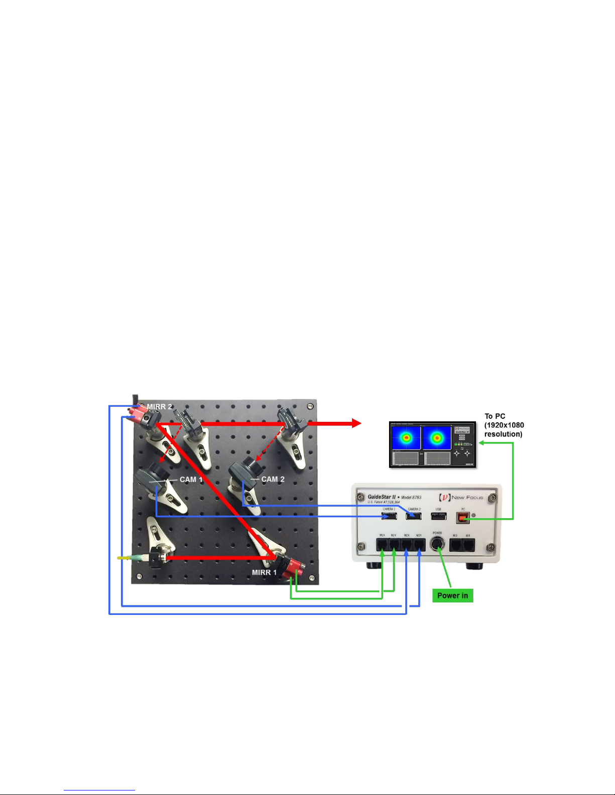
What is the best layout of the mirrors and cameras?
The best physical layout of the Picomotor Mirror Mounts (MM) and Cameras
(CAM) is such that the beam first strikes and is reflected off MM1 then MM2
with a small fraction of the light intensity then picked off for CAM 1 and CAM 2.
Please refer to Fig. 22. The best physical layout will also maximize the separation
between the two Mirror Mounts and between the two Cameras to give the most
control and highest possible resolution. For example, a 60cm minimum distance
between the two Mirror Mounts and between the two Cameras will give a
resolution of or better than 10 μrad.
It may also be useful to have the last camera image the actual working plane of
the set-up so the system stabilizes exactly on what really matters.
Figure 22. Example physical layout of mirrors and cameras for GuideStar II
system.
28
Page 34

Power in 2mm diameter beam
needed to saturate GSII Camera
1.E-09
1.E-08
1.E-07
1.E-06
1.E-05
1.E-04
1.E-03
1.E-02
1.E-01
1.E+00
300 400 500 600 700 800 900 1000 1100 1200 1300
Wavelength (nm)
1 W
1 mW
1 uW
1 nW
How do I get a low power beam into the camera?
The power required to saturate the camera is generally very low so we provide
ND-1,2, and 4 filters to attenuate any input and in the camera adjustments the
exposure time can be varied by a factor of 1000 to further attenuate or optimize
the measured intensity level. Low power beams can be measured, so it is not
necessary to use the 4% reflections of uncoated surfaces. We recommend using
the transmission through HR reflecting mirrors with polished back surfaces as the
least intrusive method in a typical optical set-up.
Figure 23. Example physical layout of mirrors and cameras for GuideStar II
system.
What is the largest beam the system can measure?
The camera aperture is 12 mm so a larger beam will over fill the camera.
What is the limiting resolution of the camera?
The pixel size resolution of the CMOS sensor is 5.2μm but the beam position
resolution is much smaller than this because the beam is measured over a large
number of pixels. The camera position resolution noise had a standard deviation
of 0.04μm and temperature drift coefficients of 3μm/°C vertical and 0.5μm/°C
horizontal. With a 2.7:1 telescope all these numbers get multiplied by 2.7.
What is the temperature sensitivity of the cameras?
Measurements of beam position in a quiet environment have shown temperature
drift coefficients of 3μm/°C vertical and 0.5μm/°C horizontal. With a 2.1:1
telescope these numbers get multiplied by 2.1.
What is the minimum angular change we can detect with the system?
The accuracy of the beam position specification of 25 µm is conservative. The
noise we see with a closed optical path measurement with no air turbulence over a
minute is < 0.1 μm. The angular change that this corresponds to depends on the
29
Page 35

distance to the mirror from the camera but if we assume > 0.1 m distance then the
angular noise is < 1 μrad. In reality we see air turbulence and temperature drifts
lead to beam noise of more than this but we have locked with targets sizes of 10
μm and distances of 2 m so angular tolerances of <5 μrad.
What is the beam pointing which results from one step on a Picomotor?
A typical Picomotor step is <30 nm and mirror mount lever arm is ~50 mm so the
angular change with one step is less than 0.6 μrad.
Do we have to set up the 2 cameras after the two mirror mounts?
It is common for set-ups to have CAM1 directly behind MM2. This is not a
configuration we recommend because in this set up any movement of MM2 will
have no effect on the beam going to CAM1 and so there are multiple solutions
for the beam to hit the two cameras.
What should I do if I don’t see the beam on one (or both) Camera(s)?
Make sure both cameras are connected to the Model 8783 Controller. If so, try
lowering the Camera Pixel Clock setting to 10-20. If the problem persists, close
the GuideStar II application and open the MicroEye Camera Manager program.
Ensure that both cameras show up in the Camera List with the appropriate
Camera ID.
How do I swap camera ID’s:
Close the GuideStar II application and start the uEye Camera Manager. Both
cameras should appear in the list. Select one, then click “Camera Information”
and change its camera ID from 1 to 2 or from 2 to 1. Click “OK”, and then do the
same for the other camera. Close the uEye Camera Manager and restart the
GuideStar II application. If the System Set-up window does not open after restarting, click the System set-up button. Perform the camera check again.
None (or only one) of my Picomotors is moving either manually or
automatically. How can I fix this?
First make sure that the each Picomotor is connected to its appropriate port on the
Model 8783 GuideStar II Controller front panel. If so, it has been found that the
best course of action is to un-install the GuideStar II application and all associated
programs/files, then re-install. This will usually do the trick.
What is the advantage using CMOS camera instead of PSD?
The position measurement performances are similar but the camera gives
information on beam size and shape as well. We use that information to make
sure the stabilization routine is “smart” and does not have any unnecessary or
dangerous beam steering.
30
Page 36

7 Maintenance and Service
7.1 Warranty
New Focus, Newport Company, guarantees its lasers to be free of defects for one
year from the date of shipment or for 3000 hours of operation, whichever comes
first. This is in lieu of all other guarantees, expressed or implied, and does not
cover incidental or consequential loss.
7.2 Technical Support
Information and advice about the operation of any New Focus product is available
from our technical support engineers. For quickest response, ask for “Technical
Support” when calling the numbers listed below and know the model and serial
number for your product.
Hours: 8:00–5:00 PST, Monday through Friday (excluding holidays).
Toll Free: 1-866-NUFOCUS (1-866-683-6287), from the USA & Canada only
Phone: (408) 284-6808
Fax: (408) 980-4300
Email: [email protected]
We typically respond to faxes and email within one business day.
7.3 Obtaining Service
The GuideStar II Controller contains no user serviceable parts. To obtain
information regarding factory service, contact New Focus or your New Focus
representative. Please have the following information available:
1. Instrument model number (on the rear panel).
2. Instrument serial number (on rear panel or bottom of enclosure).
31
Page 37

3. Description of the problem.
If the instrument is to be returned to New Focus, you will be given a Return
Material Authorization (RMA) Number, which you should reference in your
shipping documents. Please fill out a copy of the service form, located on the
following page, and have the information ready when contacting Newport
Corporation. Return the completed service form with the instrument.
32
Page 38

Page 39

 Loading...