

Page 1

Artisan Technology Group is your source for quality
new and certied-used/pre-owned equipment
• FAST SHIPPING AND
DELIVERY
• TENS OF THOUSANDS OF
IN-STOCK ITEMS
• EQUIPMENT DEMOS
• HUNDREDS OF
MANUFACTURERS
SUPPORTED
• LEASING/MONTHLY
RENTALS
• ITAR CERTIFIED
SECURE ASSET SOLUTIONS
SERVICE CENTER REPAIRS
Experienced engineers and technicians on staff
at our full-service, in-house repair center
Instra
Remotely inspect equipment before purchasing with
our interactive website at www.instraview.com
Contact us: (888) 88-SOURCE | [email protected] | www.artisantg.com
SM
REMOTE INSPECTION
View
WE BUY USED EQUIPMENT
Sell your excess, underutilized, and idle used equipment
We also offer credit for buy-backs and trade-ins
www.artisantg.com/WeBuyEquipment
LOOKING FOR MORE INFORMATION?
Visit us on the web at www.artisantg.com for more
information on price quotations, drivers, technical
specications, manuals, and documentation
Page 2

Model 3501 User’s Manual
Optical Chopper
Artisan Technology Group - Quality Instrumentation ... Guaranteed | (888) 88-SOURCE | www.artisantg.com
Page 3

Contents
I Warranty
II Introduction
III Safety and
Preparation for Use
IV Quick Start
V Operation
VI Rack Mount Kit
VII Computer Control
VIII Command Summary
3
4
6
8
9
21
22
24
351007 Rev. B
2
Artisan Technology Group - Quality Instrumentation ... Guaranteed | (888) 88-SOURCE | www.artisantg.com
IX Troubleshooting
X AC Operating
Voltages
XI Specifications
41
43
45
Is a registered trademark of
New Focus, Inc.
Page 4

Warranty
I
New Focus, Inc. guarantees the chopper head to be free of defects for 90 days
from the date of shipment. All other parts of the Model 3501 Optical Chopper
are guaranteed to be free of defects for one year from the date of shipment.
This is in lieu of all other guarantees, expressed or implied, and does not
cover incidental or consequential loss.
Artisan Technology Group - Quality Instrumentation ... Guaranteed | (888) 88-SOURCE | www.artisantg.com
3
Page 5

II
Introduction
The Model 3501 Optical Chopper is designed to interrupt light paths in optical
experiments at frequencies from 4 Hz to 6.4 kHz. Both single and dual beam
experiments can be performed across a broad range of chopping frequencies.
The chopper has a crystal controlled frequency synthesizer that serves as an
internal reference frequency for locking the chopper to a particular chopping
frequency. Reference frequencies can also be provided through the Sync Input
to allow the chopper to lock to an external source. A block diagram of the
optical chopper system is shown in Figure 1.
Several measures ensure that jitter and drift of the chopping frequency is
reduced to a minimum. Precision photo-etched wheels are mounted on a
high quality DC motor. The motor head has a photo-sensor for monitoring
the chopping frequency of the outer part of the wheel (F
). The chopper
outer
controller then actively stabilizes the motor speed to match the desired chopping frequency. This technique minimizes phase noise at the chopping frequency and provides for long-term stable chopping with a minimum of frequency drift.
Figure 1 shows a block diagram of the Model 3501 Optical Chopper system.
Programmable divide/multiply circuitry allows for harmonic or subharmonic
locking of the chopper to the reference frequency. In addition, the phase of
the chopping frequency may be varied over a -180 to +179 degree range with
respect to the reference frequency. A variety of TTL level outputs are available
for use in triggering lock-in amplifiers, oscilloscopes, photon counters or boxcar averagers.
4
Artisan Technology Group - Quality Instrumentation ... Guaranteed | (888) 88-SOURCE | www.artisantg.com
Page 6
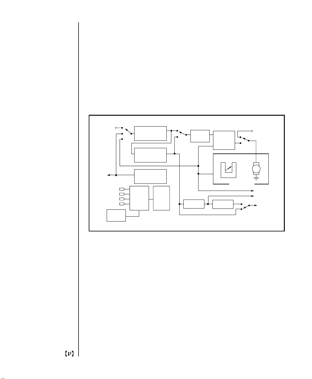
Fig. 1
Block diagram of the Model 3501 Optical Chopper.
Synch In
Synch
Out
Int
f Synch
f Outer
Out 1
Out 2
IEEE-488
Subharmonic
Divide by 1 to 15
Harmonic
Multiplier 1 to 15
Internal Frequency
Synthesizer
Micro-
processor
Front
Panel
4 Hz - 6.4 KHz
Phase
Shifter
Divide by 7
Motor
Controller
Optical Trigger
Divide by 6
Motor
Chopping Head
+/-
H/S
Norm
Ext V
f Outer
Out 2
Out 1
The chopping frequency, as well as a number of other operating parameters,
can be viewed on the front panel display, and cursor keys provide easy adjustment of operating parameters. From the front panel the user can store and
recall up to nine instrument set-ups. An IEEE-488 interface provides remote
operation of all instrument functions.
The chopper head can be mounted on a 1/2”-diameter post or bolted directly
to a standard optical bench. The Model 3501 Optical Chopper is supplied with
four chopper wheels and a wheel cover. The Model 3510 Rack Mount Kit, an
accessory that is sold separately, enables the chopper controller to be mounted
in a rack (see Page 21).
Artisan Technology Group - Quality Instrumentation ... Guaranteed | (888) 88-SOURCE | www.artisantg.com
5
Page 7

III
Safety and
Preparation
for Use
Mounting the Chopper Head
The Model 3501 Optical Chopper head may be secured to standard optical
benches using 1/4-20 or M6 bolts. The bolts pass through the mounting plate
perpendicular to the plane of the optical bench. The chopper head can be
rotated off-axis by loosening the 1/4-20 set screws on the side of the motor
mount. Do not over-tighten the set screws.
The Model 3501 Optical Chopper head may also be mounted on standard
optical bench rods. First loosen the two 1/4-20 set screws which secure the
mounting plate to the head. Remove the mounting base. Insert the 1/4-20
knob (supplied with the chopper) into the base of the head. This knob is
inserted into the same hole occupied by the dowel on the mounting plate.
Slide the motor mount onto the optical bench rod and tighten the knob. Do
not over-tighten the knob.
Mounting the Wheel
Remove power from the control unit before attempting to change the chopper
wheel. Secure the chopper head to a work surface. Remove the four 4-40
screws that secure the retaining cap over the wheel, while taking care not to
bend the wheel. Install the replacement wheel, retaining cap and 4-40 screws.
Do not over-tighten the screws.
Control Cable
Connect the 6-wire cable from the connector at the side of the chopper head to
the MOTOR connector at the back of the control unit.
WARNING: Do not connect or disconnect the chopper head while the control
unit is powered or damage to components may occur. Always shut off the
instrument and allow the motor to stop before disconnecting the cable.
6
Artisan Technology Group - Quality Instrumentation ... Guaranteed | (888) 88-SOURCE | www.artisantg.com
Page 8

Line Voltage Selection
The instrument may be damaged if operated with the line voltage selector set
at the wrong voltage or with the wrong fuses installed in the power entry
module. When the instrument ships from the factory, it will be programmed
for the standard AC voltage in the user’s country. To select a different operating voltage refer to the AC Operating Voltages section (Page 43).
Grounding
The line cord is a three-wire power cord for connection to the power mains
and a protective ground. The chassis is connected to the protective ground to
reduce the risk of electric shock. To avoid potential electrical shock, use only
mains that provide a protective ground.
Wheel Hazard
WARNING: The moving wheel may inflict injury. The operator should
assure the safety of personnel who may be exposed to this hazard.
Safety is important! The chopper wheel can cause injury if it is touched while
rotating. This is especially critical if you find yourself reaching into your optical set-up with the lights off. You may want to use the chopper wheel cover to
reduce the chance of injury.
Environment
The Model 3501 Optical Chopper may be operated in an ambient of 0 to 40
degrees C. It is recommended to avoid direct sunlight on the LED display.
WARNING: Hazardous voltages, capable of causing death, are present inside
this instrument. Do not operate the instrument with the covers removed.
Artisan Technology Group - Quality Instrumentation ... Guaranteed | (888) 88-SOURCE | www.artisantg.com
7
Page 9

IV
Quick Start
Before operating the Model 3501 Optical Chopper, please review the previous
section to make sure the chopper is ready for use.
1. Mount the chopper head securely on an optical bench.
2. Mount the 42/30 wheel on the head. Avoid bending the wheel. The wheel
should be free to turn without contact to the optical sensor or nearby
equipment.
3. Connect the cable between the chopper head and the connector marked
MOTOR on the back panel of the control unit.
4. Check that the correct line voltage has been selected and the proper fuse
inserted into the mains power entry module at the back panel of the control unit. Connect the instrument to the power mains.
5. After insuring the safety of nearby personnel, switch on the instrument.
6. Recall instrument set-up “0” (factory default setting). Press SET until
“RECALL” is lit. Press the up/down arrow keys until “0” appears in the
display window. Press the left or right arrow key to recall set-up “0”.
7. The instrument will lock at 84 Hz within 1 minute.
8. To choose a particular chopping frequency, press the Set key until the
FREQ LED is lit, and then use the up/down arrows keys to adjust the
chopping frequency.
8
Artisan Technology Group - Quality Instrumentation ... Guaranteed | (888) 88-SOURCE | www.artisantg.com
Page 10
V
Operation
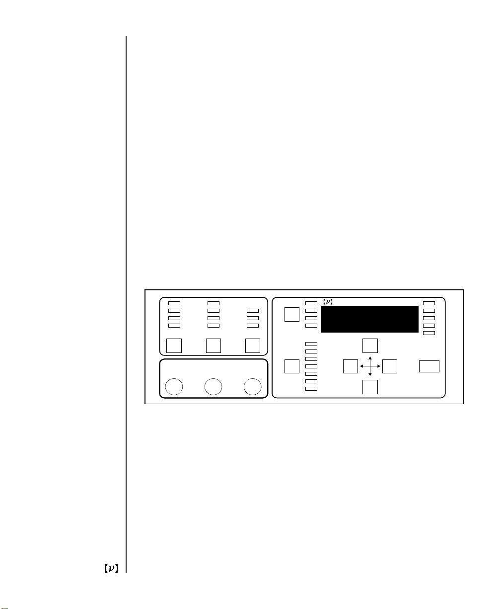
This section describes operation of the chopper, starting with an overview of
the front panel functions. This is followed by a description of the chopper
back panel and the chopper head.
60
42/30
7/5
2
Wheel Sync
Sync
Input
V ext.
EXT
EXT
Synthesizer
Output
+
-
INT
H/S
+/-
NORMAL
Mode
F Outer
Measure
Set Power
3501 Optical Chopper
SYNC IN
F outer
OUT 1
OUT 2
FREQ
PHASE
H
S
RECALL
STORE
IEEE
Fig. 2
Front panel of the Model 3501 chopper controller.
UNLCK
DEG
kHz
Hz
ACT
Made in USA
NEW FOCUS, Inc.
9
Artisan Technology Group - Quality Instrumentation ... Guaranteed | (888) 88-SOURCE | www.artisantg.com
Page 11

Front Panel
Operation
Wheel
The user may select from single or double slot wheels to perform single or
dual path experiments. Different wheel apertures may be selected to accommodate the chopping frequency of interest. The table below summarizes
wheel choices and chopping frequency ranges.
Wheel Type Lowest Frequency Highest Frequency
(slots) (F
) (F
outer
)
outer
60 120 Hz 6.40 kHz
42/30 84 Hz 4.48 kHz
7/5 14 Hz 746 Hz
2 4 Hz 213 Hz
F
is the chopping frequency as measured by an optical pick-up on the
outer
chopper head. If a wheel has two sets of slots, F
refers to the chopping
outer
frequency of the slots on the outer edge of the wheel.
To change the wheel type, push the Wheel key until the LED lights under the
desired wheel type.
10
Sync
The user may synchronize the chopping frequency to the chopper's internal
synthesizer (INT), or the rising edge (EXT+) or falling edge (EXT-) of an
externally-supplied Sync Input signal. When V
drive the motor directly with an analog voltage applied at V
panel. When using V
or INT, a signal applied to the Sync Input has no
ext
is selected, the user may
ext
on the back
ext
effect on the chopper.
To change the Sync source, press the Sync key until the LED under the desired
Sync source lights.
Artisan Technology Group - Quality Instrumentation ... Guaranteed | (888) 88-SOURCE | www.artisantg.com
Page 12

Mode
The Mode setting changes the reference signals available at OUT1 and OUT2
on the back panel as follows:
Mode F
H/S [H/S]·F
+/- F
NORMAL F
outer
sync
sync
sync
OUT1 OUT2
[H/S]·F
F
outer
5·F
sync
- F
inner
outer
[H/(7·S)]·F
F
+ F
outer
F
inner
sync
inner
To change the Mode, push the Mode key until the LED under the desired
Mode lights.
F
is the chopping frequency of the outer set of slots as measured by an
outer
optical pick-up on the chopper head. F
inner set of slots. For wheels with only one set of slots F
frequency, and F
F
is the frequency of the Sync source. In INT Sync mode, F
sync
is not defined.
inner
is the chopping frequency of the
inner
is the chopping
outer
sync
is the frequency of the chopper's internal frequency synthesizer. In EXT+ or EXT- Sync
mode, F
is the frequency of the externally supplied signal at the Sync
sync
Input.
Set
The Set key selects which instrument parameter is modified by the cursor
keys. Press SET until the LED lights under the desired parameter. The up
arrow and down arrow keys will then change the parameter value. In some
cases, the left arrow and right arrow keys select the significant digit to be
modified.
FREQ The user may set the synthesizer frequency depending on the Sync
source selected. When EXT-, EXT+ or V
sync has been selected, the fre-
ext
quency may range from 4.00 Hz to 99.9 kHz.
Artisan Technology Group - Quality Instrumentation ... Guaranteed | (888) 88-SOURCE | www.artisantg.com
11
Page 13

When INT Sync is selected, the synthesizer frequency will be restricted to the
working range of the particular chopping wheel. In H/S mode this range will
be modified by the setting of H and S. In this case, the range limits may be
calculated as follows:
F
F
upper
lower
= F
= F
[highest] · (S/H) and
outer
[lowest] · (S/H),
outer
where S,H = 1 - 15.
Setting FREQ The synthesizer frequency may be set to three significant
digits. The significant digit to be modified may be selected by the left arrow
and right arrow keys. The magnitude of the digit may be changed with the up
arrow and down arrow keys. If the display overflows or underflows, the display
will change the Hz/kHz LEDs and the decimal point to maintain three significant digits of resolution.
PHASE The phase delay may be set from +179.0° to -180.0°. The phase
shift is always referred to the chopping frequency F
modes F
outer
= F
. In H/S mode F
sync
outer
= [H/S]·F
. In NORMAL and +/-
outer
.
sync
When the phase adjustment is active, the DEG LED will be lit. The left arrow
and right arrow keys select the significant digit to be modified, and this digit
will blink. The up arrow and down arrow keys change the magnitude of the
digit.
12
H In H/S mode the user may lock the chopper to a harmonic of the sync
frequency. H is set to the harmonic of interest. Use the up arrow and down
arrow keys to set H from 1 to 15.
S The user may lock the chopper to a subharmonic of the sync frequency. S
is set to the subharmonic of interest. Use the up arrow and down arrow keys to
set S from 1 to 15. S and H may be set in any combination. Changing S only
has an effect when the chopper is in H/S mode.
STORE The user may store an instrument set-up in one of two ways. First,
the control unit will retain the control settings when the power is removed.
Artisan Technology Group - Quality Instrumentation ... Guaranteed | (888) 88-SOURCE | www.artisantg.com
Page 14

When power is restored, the instrument will recall the last control settings used.
Second, the user may utilize one of nine programmable instrument set-ups.
To store an instrument set-up press the Set key until STORE is lit. Then, use
the up arrow and down arrow keys to select instrument set-ups 1-9. Press the
left arrow or right arrow key to store the instrument’s settings at the selected
instrument set-up. The display will blink to indicate that the storage process
is complete. Location 0 is reserved for the factory default settings: 42/30
wheel, internal sync, normal mode, 84 Hz, IEEE address 12.
RECALL The user may recall instrument set-ups in one of two ways. First,
the control unit will retain the control settings when the power is removed.
When power is restored, the instrument will recall the last control settings
used.
Second, the user may utilize one of ten programmable instrument set-ups. To
recall a previously stored instrument set-up, use the up arrow and down
arrow keys to select instrument set-ups 0-9. Press the left arrow or right arrow
key to recall the selected instrument set up. The display will blink when the
recall process is complete. Location 0 is reserved for the factory default settings.
Default settings Recalling set-up ‘0’ will restore the instrument to the
factory default settings: 42/30 wheel, internal sync, normal mode, 84 Hz,
IEEE address 12.
IEEE The user may select the Model 3501’s device address on the IEEE-488
bus. The factory default setting is 12. Use the up arrow or down arrow key to
change the device address.
Measure
The Measure key selects which frequency measurement—OUT1, OUT2,
F
outer
or F
—is displayed on the front panel. The instrument will contin-
sync
ue to measure and update the display until another function key is pressed.
Artisan Technology Group - Quality Instrumentation ... Guaranteed | (888) 88-SOURCE | www.artisantg.com
13
Page 15

To change the Measure parameter, press the Measure key until the LED lights
under the desired parameter.
Sync Input
The user may connect a TTL level sync frequency at the Sync Input. EXT+ or
EXT- sync must be selected and the frequency must remain within the limits
defined above in the FREQ section. The UNLCK LED will blink if the Sync
Input frequency is outside the limits.
Synthesizer Output
The instrument provides the user with a TTL level square wave output for use
in experiments. The Synthesizer Output frequency is adjusted by setting the
FREQ parameter from the front panel or via IEEE-488. With INT sync active,
the frequency will be limited as given above in the FREQ section. With EXT+,
EXT- or V
F
outer
, the Synthesizer Output ranges from 4.00 Hz to 99.9 kHz.
ext
The instrument provides the user with a TTL level square wave generated
from an optical pick-up on the chopper head.
14
ACT
The ACT LED indicates when the IEEE-488 interface is busy.
UNLCK
The red UNLCK LED indicates when the chopper is not synchronized to an
internal or external sync frequency. The UNLCK LED will blink when an
external sync frequency exceeds the limits for a particular wheel.
Artisan Technology Group - Quality Instrumentation ... Guaranteed | (888) 88-SOURCE | www.artisantg.com
Page 16
Back Panel
Operation
OUT1
The function of the OUT1 output depends on the instrument’s operating
mode. In H/S mode, the instrument provides a TTL level pulse at frequency [H/S]·F
F
- F
outer
inner
. In +/- mode the frequency at OUT1 is
sync
, and in NORMAL mode the frequency is 5·F
outer
.
OUT2
The function of the OUT2 output depends on the instrument’s operating
mode. In H/S mode, the instrument provides the user with a TTL level
pulse at frequency [H/(7·S)]·F
is F
outer+Finner
, and in NORMAL mode the frequency is F
. In +/- mode the frequency at OUT2
sync
inner
.
OUT 1 OUT 2
TTL
TTL
IEEE-488 MOTOR
V ext
-10V=100%
WARNING: High voltage
inside. Refer to qualified
technician for service.
VOLTS AC SLO-BLO FUSE
100-120
0.4 AMP
220-240
0.2 AMP
120 Vac
MADE IN THE U.S.A.
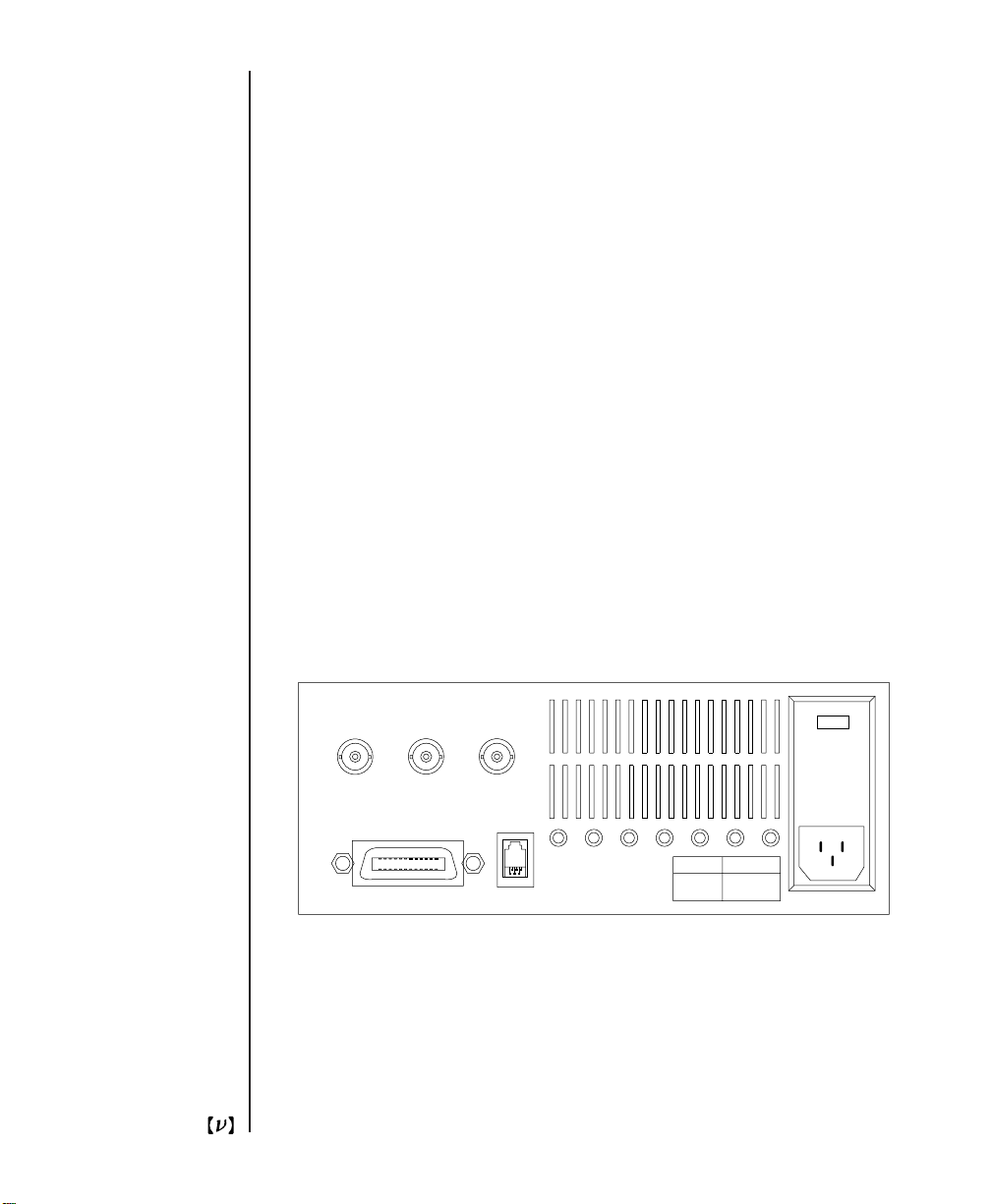
Fig. 3
Back panel of the chopper controller.
Artisan Technology Group - Quality Instrumentation ... Guaranteed | (888) 88-SOURCE | www.artisantg.com
15
Page 17

V
ext
When V
sync is selected, the user may drive the chopper motor directly with
ext
a DC input voltage. 0 to -10 V DC corresponds to 0 to 100% of the highest
motor speed.
MOTOR
Use the supplied cable to connect the chopping head to the chopper controller
at the back panel.
IEEE-488
The instrument may be programmed remotely via IEEE-488. Use a standard
cable to connect the instrument to the host computer system.
Power entry module
The AC power is connected at the power entry module on the back panel. The
line voltage and power cord have been chosen at the factory to match the
country of consignment. If it is necessary to change the mains voltage, consult the section on AC Operating Voltages (Page 43).
16
Artisan Technology Group - Quality Instrumentation ... Guaranteed | (888) 88-SOURCE | www.artisantg.com
Page 18
Chopper Head
Cable
The cable that connects the control unit to the chopper head is a six conductor reverse RJ11 type IDC telephone cable. Connect the cable from the connector on the side of the chopper head to the MOTOR connector on the back
panel of the control unit. The instrument has been tested with cable lengths
up to 25 feet, but the chopper is supplied with a shorter cable. Replacement
cables and longer cables may be purchased from electronics parts suppliers
such as Digi-Key (Part # H2662-14-ND).
5.00" (127.0)
2.00" (50.8)
2.88" (73.2)
5.74 " (145.8)
5.48" (139.2)
4.03" (102.4)
0.50" (12.7)
2.25" (57.1)
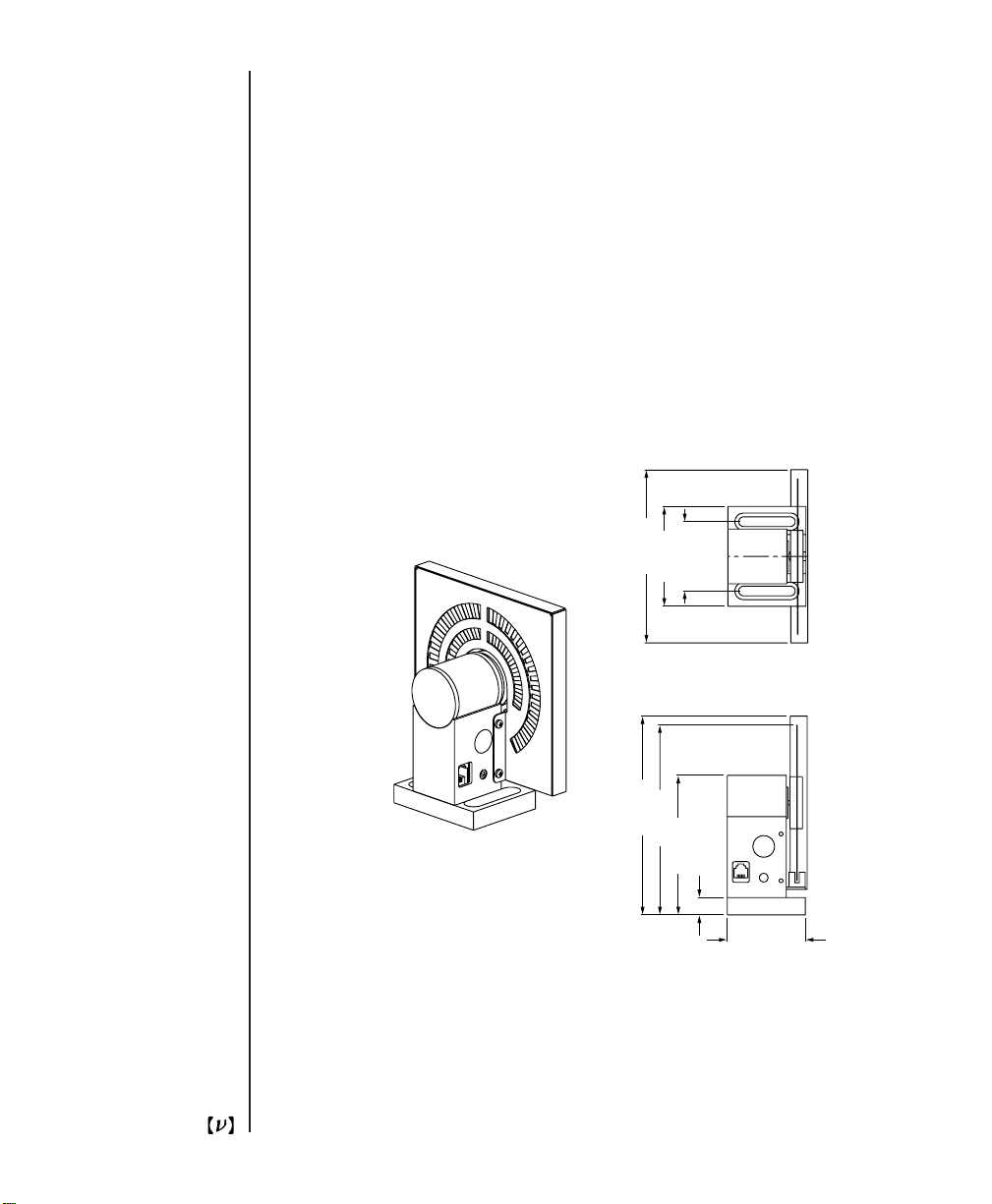
Fig. 4
Chopper head with wheel cover.
Artisan Technology Group - Quality Instrumentation ... Guaranteed | (888) 88-SOURCE | www.artisantg.com
17
Page 19

Mounting the Chopper Head
The Model 3501 Optical Chopper head may be secured to standard optical
benches using 1/4-20 or M6 bolts. The bolts pass through the mounting plate
perpendicular to the plane of the optical bench. This mounting method provides the advantage of allowing the wheel to be rotated off-axis by loosening
the 1/4-20 set screws on the side of the motor mount. Do not over-tighten the
set screws.
The Model 3501 Optical Chopper head may also be mounted on standard
optical bench rods. First loosen the two 1/4-20 set screws that secure the
mounting plate to the head. Remove the head. Insert the 1/4-20 knob into
the base of the head. This knob is inserted into the same hole occupied by the
dowel on the mounting plate. Slide the head onto the optical bench rod and
tighten the knob. Do not over-tighten the knob.
Chopper Motor
The operating life of the chopper motor is limited. Long term use of the
motor at high speed will result in faster wear and shorter life. Contact New
Focus for details about replacing the motor, if this becomes necessary.
18
Mounting the Wheel
Remove power from the control unit before attempting to change the chopper
wheels. Secure the chopping head to a work surface. Remove the four 4-40
screws that secure the retaining cap over the wheel, while taking care not to
bend the wheel. Install the replacement wheel, retaining cap and 4-40 screws.
Do not over-tighten the screws.
Artisan Technology Group - Quality Instrumentation ... Guaranteed | (888) 88-SOURCE | www.artisantg.com
Page 20
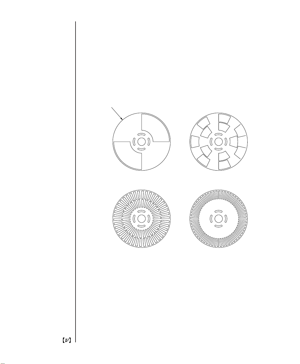
Diameter 4.50" (114.3 mm)
2 Slot
42/30 Slot
7/5 Slot
60 Slot
Fig. 5
The four chopper wheels that are supplied with the chopper.
19
Artisan Technology Group - Quality Instrumentation ... Guaranteed | (888) 88-SOURCE | www.artisantg.com
Page 21

Wheel Cover
The wheel cover attaches to the chopper head with 4 screws. The wheel cover
is made of .030” aluminum with an anti-reflective black anodized coating.
Two concentric slots, etched in both faces of the cover, allow apertures up to .3
and .4-inches wide over most of the chopping wheel surface. The wheel cover
dimensions are 5” x 5” x 0.5”.
The wheel cover is provided for safety. The chopper wheel can cause injury if
it is touched while rotating. This is especially critical if you find yourself
reaching into your optical set-up with the lights off.
The wheel cover is also provided to reduce the generation of stray light that
could interfere with your measurements. The chopper head uses an infrared
sensor to detect chopper wheel motion. The source in this sensor emits energy
in the 870 - 950 nm wavelength range. The wheel cover will greatly reduce
the amount of sensor-radiated IR light picked up by your detector.
To install the wheel cover, first install a wheel on the chopper hub. Then, slide
the wheel cover over the top of the wheel while spreading the 2 mounting
flanges apart enough to avoid contact with the painted motor surface. (The
motor is .060 - .080” wider than the mounting base.) Once the mounting
flanges are lowered past the motor, align one of the 4 flange holes with a
threaded hole in the motor base and loosely attach the cover to the base with
one of the 4-40 x 3/8” mounting screws. Loosely fasten the 3 remaining
screws. Tighten the 4 screws after they are installed.
20
The cover must be removed to change the chopping wheel. Remove the 4
screws holding the cover to the base. From the motor side of the chopping
wheel, move the cover away from the motor while spreading the mounting
flanges apart. Now slide the cover up over the motor.
Artisan Technology Group - Quality Instrumentation ... Guaranteed | (888) 88-SOURCE | www.artisantg.com
Page 22
VI
Rack
Mount Kit
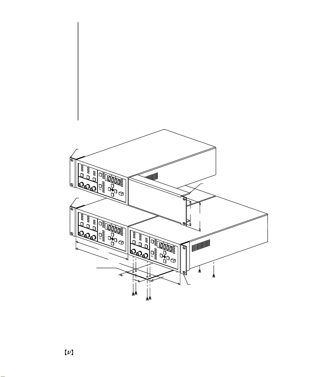
The Model 3510 Rack Mount Kit is a chopper accessory (not supplied with the
Model 3501 Optical Chopper) that allows one or two chopper controllers to be
mounted in a standard rack. The kit consists of 2 short ears, 1 long ear, 1 rack
plate, and 6 6-32 flathead screws. The figure below illustrates how to use the
rack mount kit to mount a single chopper controller or two chopper controllers side by side.
#3510 Rack Mount Kit consists of:
2 short ears
1 long ear
Short Ear
Short Ear
Made in USA
NEW FOCUS, Inc.
Long Ear
3.00"
3.48"
1 rack plate
6 6-32 flathead screws
Made in USA
NEW FOCUS, Inc.
Rack Plate
(connects two
units together)
8.50"
17.00"
3.30"
Made in USA
NEW FOCUS, Inc.
12.35"
Short Ear
Fig. 6
Model 3510 rack mount kit.
Artisan Technology Group - Quality Instrumentation ... Guaranteed | (888) 88-SOURCE | www.artisantg.com
21
Page 23

VII
Computer
Control
The Model 3501 Optical Chopper may be programmed remotely by IEEE-488
interface. The Model 3501 supports the IEEE-488.1 (1978) interface standard,
and any computer that supports this interface may be used. A total of fifteen
commands are available that enable any front panel operation to be performed remotely.
Before communicating with the chopper controller, set the IEEE-488 device
address. This parameter may be selected by pressing the Set key until the IEEE
LED is lit. Use the arrow keys to change the device address. The default device
address is 12. Use a standard IEEE-488 cable to connect the instrument to the
host computer.
ACT LED
The ACTive LED flashes whenever data is sent or received on the communications interface.
Line Terminators
22
For IEEE-488 operation, the correct line termination is line feed and EOI
('end or identify'). Generally, line terminations are set during the installation
of the IEEE-488 interface card. Consult the manufacturer's installation
instructions for details.
Command Syntax
Use ASCII characters to communicate with the Model 3501. Commands may
be issued either in upper or lower case.
Some commands can be used to set operating parameters, some commands
can be used to query operating parameters, and some commands can do
both. A command (e.g., WHL?) consists of a mnemonic (WHL) and a optional
suffix (?). The three letter mnemonic (WHL) specifies the parameter or action
Artisan Technology Group - Quality Instrumentation ... Guaranteed | (888) 88-SOURCE | www.artisantg.com
Page 24

to be taken by the Model 3501. The suffix “?” indicates the command is a
query that requests data from the Model 3501. The “WHL2” command is used
to set the type of wheel being used, and in this case, “2” is taken as a parameter value.
Do not include decimal points in numerical data. So, to set the chopper frequency to 1.23 kHz, send the command OSC123000. To set the phase to -90
degrees, send the command PHS-900.
Multiple commands on a single line must be separated by a semicolon (;).
Data to Host
Data returned by the chopper controller to the host computer consist of a
mnemonic, a data value and a line terminator. The mnemonic specifies the
parameter (WHL = wheel) or the quantity measured (FR1 = F
sync
frequen-
cy). Data is returned by the chopper with decimal points included (e.g.,
1230.0).
Data to the host will be followed with a line termination (line feed and EOI).
The line termination may be set when installing IEEE-488 into the host computer. Consult the manufacturer’s installation guide for details.
Artisan Technology Group - Quality Instrumentation ... Guaranteed | (888) 88-SOURCE | www.artisantg.com
23
Page 25

VIII
Command
Summary
Commands that may be queried are followed by a ‘?’.
A ‘*’ indicates that the command contains an index (e.g., FR1,FR2,...).
A bracket [ ] indicates that the command accepts a data value. Data ranges
are given in parenthesis. Do not use a decimal point or comma in data. For
example, 5.00 is sent as 500.
Some commands can be used both to set and query an operating parameter.
For instance, the PHS command can be used to set the chopping phase
(PHS900) or to read the value of the phase (PHS?).
The next two pages contain an index and brief description of all fifteen commands. Then, the pages that follow give detailed information about each
command. There, examples are given showing the command text followed by
the response from the chopper. For instance, the example for IDN? appears as
follows:
IDN?
—>NEW FOCUS 3501 CHOPPER
Command Index
24
Artisan Technology Group - Quality Instrumentation ... Guaranteed | (888) 88-SOURCE | www.artisantg.com
FR*? Measures frequency. 1 - F
4 - OUT2.
HAR[ ]? Sets the harmonic multiplier H (1 - 15).
IDN? Identification query. Returns “NEW FOCUS 3501
CHOPPER”.
KEY* Duplicates the action of pressing a front panel key:
0 - Right arrow, 1 - Down arrow, 2 - Up arrow, 3 - Left arrow,
4 - Set, 5 - Measure, 6 - Mode, 7 - Sync, 8 - Wheel.
sync
, 2 - F
outer
, 3 - OUT1,
Page 26

MEM* Accesses instrument set-up memory. 0 - Store, 1 - Recall. Use
with STO and RCL commands.
MOD*? Selects the instrument mode. 0 - H/S, 1 - +/-, 2 - NORMAL.
MSK[ ]? Enables condition required for SRQ (service request).
Bit 0 - Unlock, Bit 1 - Data Ready.
OSC[ ]? Sets the synthesizer frequency to three significant digits.
(4.00 Hz - 99.9 kHz in EXT mode; range automatically
limited in INT mode).
PHS[ ]? Sets the phase delay (-180.0 - +179.0).
RCL[ ]? Selects instrument set-up for recall (0-9). 0 - factory default
set-up. Use with MEM1 command.
SET* Selects the parameter modified by the arrow keys:
0 - Oscillator frequency, 1 - Phase, 2 - Harmonic multiplier,
3 - Subharmonic divide ratio, 4 - Recall set-up,
5 - Store set-up, 6 - GPIB device address.
STA? Returns status register. Bit 0 - Unlock, Bit 1 - Data Available.
The same information is available during a Serial Poll.
STO[ ]? Selects instrument set-up for storage (1-9). Use with MEM0
command.
SUB[ ]? Sets subharmonic divide ratio S (1 - 15).
WHL*? Selects the wheel. 0 - 60 slots, 1 - 42/30 slots, 2 - 7/5 slots,
3 - 2 slots.
Artisan Technology Group - Quality Instrumentation ... Guaranteed | (888) 88-SOURCE | www.artisantg.com
25
Page 27

Command
FR*?
Description
Explanation
Example
Frequency query.
The FR* command is used to query the following frequencies associated with
the Measure key on the chopper front panel: F
sync
, F
, OUT1, and OUT2.
outer
Data is returned in Hz.
FR1? - F
FR2? - F
sync
outer
FR3? - OUT1
FR4? - OUT2
The chopping frequency is 1.23 kHz, and the chopper is in NORMAL mode.
FR1?
—>FR11230.0
FR2?
26
—>FR21230.0
FR3?
—>FR36150.0 (The frequency at OUT1 is 6.15 kHz.)
Artisan Technology Group - Quality Instrumentation ... Guaranteed | (888) 88-SOURCE | www.artisantg.com
Page 28

Command
HAR[ ]?
Description
Explanation
Example
Set and query H.
The HAR command sets and queries the harmonic multiplier H, which is
used in H/S mode. The data may range from 1 to 15.
HAR2 (Sets H to 2.)
HAR?
—>HAR2
Artisan Technology Group - Quality Instrumentation ... Guaranteed | (888) 88-SOURCE | www.artisantg.com
27
Page 29

Command
IDN?
Description
Explanation
Example
Identification query.
Returns the following string identifying the chopper: "NEW FOCUS 3501
CHOPPER"
IDN?
—>NEW FOCUS 3501 CHOPPER
28
Artisan Technology Group - Quality Instrumentation ... Guaranteed | (888) 88-SOURCE | www.artisantg.com
Page 30

Command
KEY*
Description
Explanation
Duplicates the action of pushing a front panel button.
The KEY command duplicates the action of pushing one of the 9 black front
panel buttons. The nine options are as follows:
KEY0 - Right arrow
KEY1 - Down arrow
KEY2 - Up arrow
KEY3 - Left arrow
KEY4 - Set
KEY5 - Measure
KEY6 - Mode
KEY7 - Sync
KEY8 - Wheel
Artisan Technology Group - Quality Instrumentation ... Guaranteed | (888) 88-SOURCE | www.artisantg.com
29
Page 31

Command
MEM*
Description
Explanation
Example
Store and recall instrument set-ups.
The MEM command, along with the STO and RCL commands, is used to
store and recall one of the 9 instrument set-ups.
After selecting which instrument set-up number to use (1 through 9) using
the STO command, MEM0 will store the current instrument set-up.
After selecting which instrument set-up to recall using the RCL command,
MEM1 recalls the selected set-up.
MEM0 - Store instrument set-up.
MEM1 - Recall instrument set-up.
STO5 (Selects location #5 for storing the current chopper set-up.)
MEM0 (Activates storage to location #5.)
RCL1 (Selects location #1 for recalling a chopper set-up.)
30
MEM1 (Activates recall of the set-up stored in location #1.)
Artisan Technology Group - Quality Instrumentation ... Guaranteed | (888) 88-SOURCE | www.artisantg.com
Page 32

Command
MOD*?
Description
Explanation
Example
Select and query the mode of operation.
The MOD command allows the user to query the chopper’s operating mode
and to set the chopper operating mode as follows:
MOD0 - H/S
MOD1 - +/-
MOD2 - NORMAL
MOD2 (Puts the chopper into NORMAL operating mode.)
MOD?
—>MOD2
Artisan Technology Group - Quality Instrumentation ... Guaranteed | (888) 88-SOURCE | www.artisantg.com
31
Page 33

Command
MSK[ ]?
Description
Explanation
Example
Enables condition required for SRQ.
The MSK command sets or clears bits in the SRQ (service request) enable
mask. A Service Request will be generated whenever either of the following
bits is set. D0 (the rightmost bit) is for Unlock, and D1 (the next bit to the
left) is for Data Available.
The MSK? query returns the SRQ enable mask.
MSK1 (Generates a SRQ on Unlock.)
MSK?
—>MSK00000001
MSK10 (Generates a SRQ when data is available.)
MSK?
—>MSK00000010
32
MSK11 (Generates a SRQ on Unlock or when data is available.)
MSK?
—>MSK00000011
Artisan Technology Group - Quality Instrumentation ... Guaranteed | (888) 88-SOURCE | www.artisantg.com
Page 34

Command
OSC[ ]?
Description
Explanation
Example
Set and query the synthesizer frequency.
The OSC command sets and queries the internal synthesizer. In INT Sync
mode setting the synthesizer frequency will set the chopping frequency. In
INT Sync mode the data supplied by the OSC command is limited by the
chopper wheel minimum and maximum chopping frequencies. In the other
modes of operation, the data may range from 4.00 to 99.9 kHz.
Only three digits of resolution are available. The data is entered in Hz, and no
decimal point should be included.
OSC54300 (Sets the internal synthesizer to 543 Hz.)
OSC?
OSC543.00
Artisan Technology Group - Quality Instrumentation ... Guaranteed | (888) 88-SOURCE | www.artisantg.com
33
Page 35

Command
PHS[ ]?
Description
Explanation
Example
Set and query the phase delay.
The PHS command sets and queries the phase shifter. The data may range
from -180.0 to +179.0 degrees. Do not use a decimal point in the data.
PHS-1234 (Sets the phase shift to -123.4 degrees.)
PHS?
—>PHS-123.4
PHS222 (Sets the phase shift to 22.2 degrees.)
34
Artisan Technology Group - Quality Instrumentation ... Guaranteed | (888) 88-SOURCE | www.artisantg.com
Page 36

Command
RCL[ ]?
Description
Explanation
Example
Selects instrument set-up for recall.
The RCL command will select a formerly stored instrument set-up. The RCL?
query will return the recall set-up number. The data may range between 0
and 9. Recall of set-up ‘0’ will restore the Model 3501 to factory default settings. RCL is used with MEM1 to recall the instrument set-up.
RCL0 (Select factory default set-up for recall.)
MEM1 (Perform recall operation.)
RCL4 (Select instrument set-up #4 for recall.)
RCL?
—>RCL4
MEM1 (Perform recall operation.)
Artisan Technology Group - Quality Instrumentation ... Guaranteed | (888) 88-SOURCE | www.artisantg.com
35
Page 37

Command
SET*
Description
Explanation
Selects the parameter to be modified by the arrow keys.
The set command selects which parameter is activated so that it can be
changed by the arrow keys.
SET0 - Synthesizer frequency
SET1 - Phase
SET2 - H
SET3 - S
SET4 - Recall
SET5 - Store
SET6 - IEEE-488 device address
36
Artisan Technology Group - Quality Instrumentation ... Guaranteed | (888) 88-SOURCE | www.artisantg.com
Page 38

Command
STA?
Description
Explanation
Returns the status register.
The STA query returns the 8-bit status register. The status register indicates
when the instrument is unlocked (first bit) and when the data is available
(second bit). Since some commands require a wait before the data is available (e.g., FR1?), the user may wish to poll the instruments to determine
when to collect the data. Note: A serial poll of the instrument provides the
same information without generation of additional data ready messages.
The bits in the status register are arranged from right to left as shown below
(i.e., D0 is the rightmost bit). A value of 1 indicates the bit has been set, and a
value of 0 indicates the bit is clear. Format of the bits in the status register:
D0 - Unlock (sampled)
D1 - Data available
D2 - Synthesizer locked (sampled)
D3 - Multiplier locked (sampled)
D4 - Motor locked (sampled)
D5 - Latched master unlock
D6 - Reserved for calibration
D7 - Reserved for calibration
The master unlock bit (D5) will be cleared when the status register is read
with the STA? command. The master unlock will be set if the motor, multiplier, or synthesizer has been unlocked between the last and the current reading
of the status register.
Artisan Technology Group - Quality Instrumentation ... Guaranteed | (888) 88-SOURCE | www.artisantg.com
37
Page 39

Command
ST0[ ]?
Description
Explanation
Example
Selects instrument set-up for storage.
The STO command selects the instrument set-up number in which to store
the current chopper set-up. The STO? query will return the selected instrument set up number. The data may range from 1 to 9. STO is used with
MEMO to store the instrument set-up.
ST09 (Select instrument set-up #9 for storage.)
STO?
—>STO9
MEMO (Perform storage operation.)
38
Artisan Technology Group - Quality Instrumentation ... Guaranteed | (888) 88-SOURCE | www.artisantg.com
Page 40

Command
SUB[ ]?
Description
Explanation
Example
Set and query S.
The SUB command sets and queries S, the subharmonic divide ratio which is
used in H/S mode. The data may range from 1 to 15.
SUB7 (Sets S to 7.)
SUB?
—>SUB7
Artisan Technology Group - Quality Instrumentation ... Guaranteed | (888) 88-SOURCE | www.artisantg.com
39
Page 41

Command
WHL[ ]?
Description
Explanation
Example
Set and query the type of chopping wheel being used.
The WHL command sets and queries the type of chopping wheel that is being
used:
WHL0 - 60 slots
WHL1 - 42/30 slots
WHL2 - 7/5 slots
WHL3 - 2 slot
WHL1 (Selects the 42/30 slot wheel.)
WHL?
—>WHL1
40
Artisan Technology Group - Quality Instrumentation ... Guaranteed | (888) 88-SOURCE | www.artisantg.com
Page 42

IX
Troubleshooting
When the instrument is properly connected to the power mains and a chopper
head, and the unit is turned on, the front panel LEDs will blink and the display will show ‘PASS’ before recalling the last control set up. The motor
should begin turning and come to speed within about 1 minute.
If nothing happens
Check that the power cord is connected at the power entry module.
Check that the chopping head is connected to the control unit. Do not connect the chopping head when the control unit is powered.
Fuse
Check the fuses in the power entry module. Disconnect the power cord at the
power entry module. Open the cover of the power entry module using a smallblade screwdriver or similar tool. Slide the fuse holders out and examine the
fuses. Replace a blown fuse with the appropriate type and current rating. (For
additional details, see page 44.)
Mains Voltage
Make sure that the power entry module is set for the correct mains voltage. To
set the mains voltage, refer to AC Operating Voltages (page 43).
Fails test at start up
This indicates a failure of the battery-backed memory. Consult with the factory for a replacement battery. Instrument settings will not be maintained when
power is removed.
Artisan Technology Group - Quality Instrumentation ... Guaranteed | (888) 88-SOURCE | www.artisantg.com
41
Page 43

Motor fails to turn
With power removed from the control unit, check that the wheel is free to
turn without obstructions. Also, this condition may be caused by a broken
cable between the control unit and the head. Substitution of a known functional cable is the best solution. (See Page 17 for details on replacement
cables.)
Note that the life of the motor is limited. Long term high speed use of the
motor will result in faster wear and shorter life. Because of this limited lifetime, the chopper head has a 90 day warranty, while all other parts have a
one year warranty.
Motor oscillates wildly
Recall the factory default settings. This will place the instrument into known
conditions. If the oscillation stops, then the Sync Input signal may have been
unstable. Verify the stability of Sync Input with an oscilloscope or frequency
counter. The Sync Input frequency may have been outside of operating limits
which are determined by the mode, H, S and the wheel type. Refer to the section on FREQ for more details.
42
Observe F
on an oscilloscope. If the cable or optical sensor is damaged,
outer
the signal will remain high or low. If this is the case replace the cable between
the head and the control unit.
Check for the correct setting of Wheel on the front panel.
Artisan Technology Group - Quality Instrumentation ... Guaranteed | (888) 88-SOURCE | www.artisantg.com
Page 44

X
AC
Operating
Voltages
The Model 3501 Optical Chopper can operate at 100, 120 , 220, or 240 V AC at
AC frequencies of 47-63 Hz. The unit is configured at the factory for the standard AC voltage in the purchaser’s country. To select a different operating voltage, please refer to Fig. 7 (page 44) and follow the directions below:
1. Disconnect the power cord.
2. Open the cover of the power entry module on the rear panel with
a small-blade screwdriver or similar tool.
3. Insert the tool into the voltage selection slot and remove the wheel from
the unit.
4. Turn the wheel and re-insert into the module so the desired voltage is
shown. Do not attempt to rotate the wheel while it is still in the power
entry module; the wheel must be removed, turned, and then re-inserted.
5. Close the cover.
6. Verify that the proper voltage is showing through the module’s window.
Artisan Technology Group - Quality Instrumentation ... Guaranteed | (888) 88-SOURCE | www.artisantg.com
43
Page 45
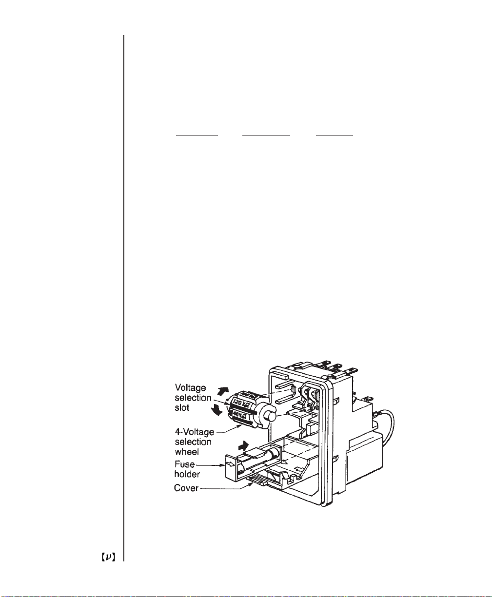
The power entry module requires two 5x20 mm, slow-blow fuses, such as
®
Littlefuse’s
Slo-Blo®239 series: one for the hot line and the other for the
neutral line. Replacement fuses should be as follows:
AC V
oltage Fuse Rating Littlefuse
100 V AC 0.4 A 239.400
120 V AC 0.4 A 239.400
220 V AC 0.2 A 239.200
240 V AC 0.2 A 239.200
Figure 7
Power entry module for the Model 3501 Optical Chopper.
44
Artisan Technology Group - Quality Instrumentation ... Guaranteed | (888) 88-SOURCE | www.artisantg.com
Page 46

XI
Specifications
Chopping Frequency
Wheel Min. Freq. Max. Freq. Jitter (µs p-p)
(F
)(F
outer
) @ Min. Freq. @ Max. Freq.
outer
60 120 Hz 6.40 kHz 60 2
42/30 84 Hz 4.48 kHz 50 2
7/5 14 Hz 746 Hz 500 3
2 4 Hz 213 Hz 500 5
Internal Synthesizer
Stability 100 ppm after one hour warm-up.
Drift Less than 10 ppm/°C.
Accuracy < 1/5 of least significant digit.
Resolution 4.00 Hz - 99.9 kHz, 3 significant digits.
Range limits (INT) Upper: [Highest wheel frequency]·S/H.
Lower: [Lowest wheel frequency]·S/H.
Range limits (EXT) 4.00 Hz - 99.9 kHz.
Reference Input
Sync Input TTL level pulse, with same frequency limits as
internal oscillator.
Artisan Technology Group - Quality Instrumentation ... Guaranteed | (888) 88-SOURCE | www.artisantg.com
45
Page 47

Reference Output
Sync Out TTL level square wave, may be used as free running
oscillator when using EXT+, EXT- or V
ext
sync.
F
outer
OUT1 TTL level pulse: 5·F
OUT2 TTL level pulse: F
TTL level square wave at the chopping frequency.
outer
F
- F
outer
[H/S]·F
F
outer
in NORMAL mode
inner
+ F
outer
[H/(7·S)]·F
Phase Shifter
Range: -180.0° to +179.0°
Resolution: 0.1°, increasing to 0.25° at 6.4 kHz.
Harmonic Locking
Subharmonic (S): 1 - 15
Harmonic (H): 1 - 15
S and H may be set in any combination.
in NORMAL mode
in +/- mode
inner
in H/S mode.
in +/- mode
inner
in H/S mode.
sync
46
Operation
Mode S H OUT1 OUT2
H/S 1-15 1-15 [H/S]·F
+/- 1 12 F
outer
NORMAL 1 5 5·F
Artisan Technology Group - Quality Instrumentation ... Guaranteed | (888) 88-SOURCE | www.artisantg.com
sync
- F
outer
inner
[H/(7·S)]·F
F
+ F
outer
F
inner
sync
inner
Page 48

External Voltage Control
0 to -10.0 V DC for 0 to 100% of maximum chopping frequency.
Wheel Apertures
Wheel Outer Aperture Inner Aperture
(inches) (inches)
60 .09 —
42/30 .14 .12
7/5 .60 .59
2 1.25 —
General
Dimensions: 8.5 x 4 x 14.5 inches
Weight: 14 pounds
Power: 90-240 V AC, 50-60 Hz, 35 W
Artisan Technology Group - Quality Instrumentation ... Guaranteed | (888) 88-SOURCE | www.artisantg.com
47
Page 49

48
Artisan Technology Group - Quality Instrumentation ... Guaranteed | (888) 88-SOURCE | www.artisantg.com
Page 50

Artisan Technology Group is your source for quality
new and certied-used/pre-owned equipment
• FAST SHIPPING AND
DELIVERY
• TENS OF THOUSANDS OF
IN-STOCK ITEMS
• EQUIPMENT DEMOS
• HUNDREDS OF
MANUFACTURERS
SUPPORTED
• LEASING/MONTHLY
RENTALS
• ITAR CERTIFIED
SECURE ASSET SOLUTIONS
SERVICE CENTER REPAIRS
Experienced engineers and technicians on staff
at our full-service, in-house repair center
Instra
Remotely inspect equipment before purchasing with
our interactive website at www.instraview.com
Contact us: (888) 88-SOURCE | [email protected] | www.artisantg.com
SM
REMOTE INSPECTION
View
WE BUY USED EQUIPMENT
Sell your excess, underutilized, and idle used equipment
We also offer credit for buy-backs and trade-ins
www.artisantg.com/WeBuyEquipment
LOOKING FOR MORE INFORMATION?
Visit us on the web at www.artisantg.com for more
information on price quotations, drivers, technical
specications, manuals, and documentation
 Loading...