

Page 1

Model 3211 User’s Manual
High-Voltage Amplifier
Page 2

2
The symbol and NEW FOCUS, Inc. are registered trademarks of New Focus, Inc.
Copyright 1999, New Focus, Inc. All rights reserved.
321101 Rev. B
Page 3

Contents
Introduction
Safety
Operation
Applications
Appendix 1:
Bandwidth Limitations
Appendix 2:
Operating Voltages & Fuses
Specifications
Warranty, Service, & Support
4
5
6
10
12
16
18
19
3
Page 4

Introduction
The New Focus Model 3211 High-voltage Amplifier
can be used as a versatile gain block in applications involving high-speed and high-voltage signals. The amplifier is extremely linear and can be
used to drive capacitive loads up to 100 nF with
peak voltages up to ±200 V. These features make
the device useful for driving electro-optic modulators and piezo-electric transducers. For instance,
with the Model 400X Electro-optic Phase Modulators, the Model 3211 can be used to provide a lin-
ear phase modulation of greater than πfor fre-
quencies up to 1 MHz. The amplifier can also provide output current up to 120 mA.
4
Page 5

5
Safety
The Model 3211 is a high-voltage amplifier capable of putting out 200 V at 120 mA. Because of the
high-voltage capabilities of the amplifier, proper
precautions should be taken to avoid electrical
shock. The unit is equipped with a High Voltage
On/Off switch which acts independently of the
AC power switch. The three high-voltage outputs
(High-voltage Output, -200 V and +200 V) will not
operate unless the front-panel rocker Power switch
is on and the green LED light is indicated on the
High Voltage On/Off switch.
In the typical application, the user may not want
to use the ±200 V outputs. Since these outputs are
turned on when the High-voltage Output is enabled, New Focus recommends putting dust covers
over these ±200 V outputs (which are DC current
limited to 2 mA) when they are not being used to
avoid electrical shock.
NOTE: Your safe and effective use of this product
is of utmost importance to New Focus. Please read
through the entire manual before attempting to
operate the amplifier.
Page 6

6
Operation
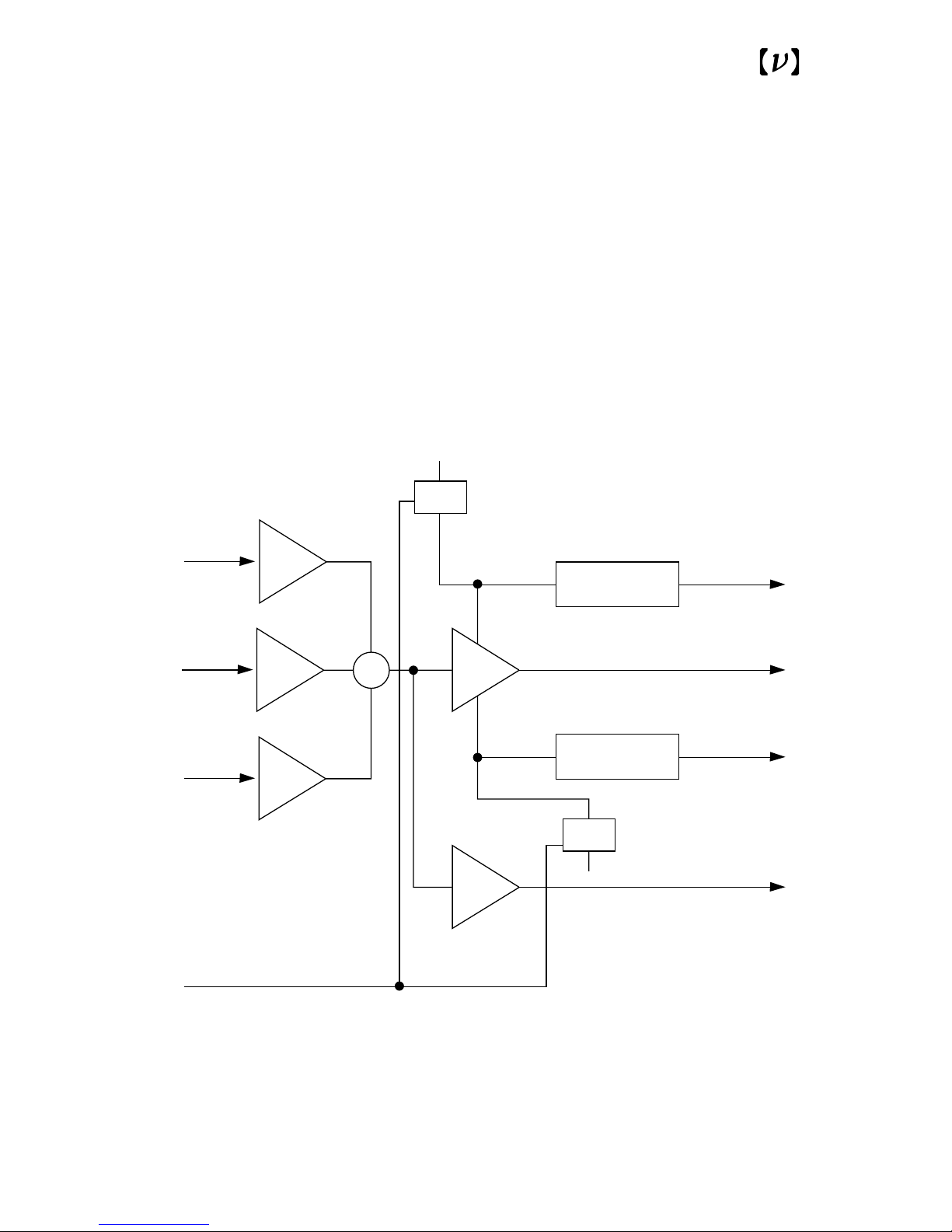
The Model 3211 consists of a current-limited,
high-voltage operational amplifier used in a
summing-amplifier configuration. As shown in
Fig.1, three signals are summed together at the
input and amplified: DC offset, Input 1, and Input 2.
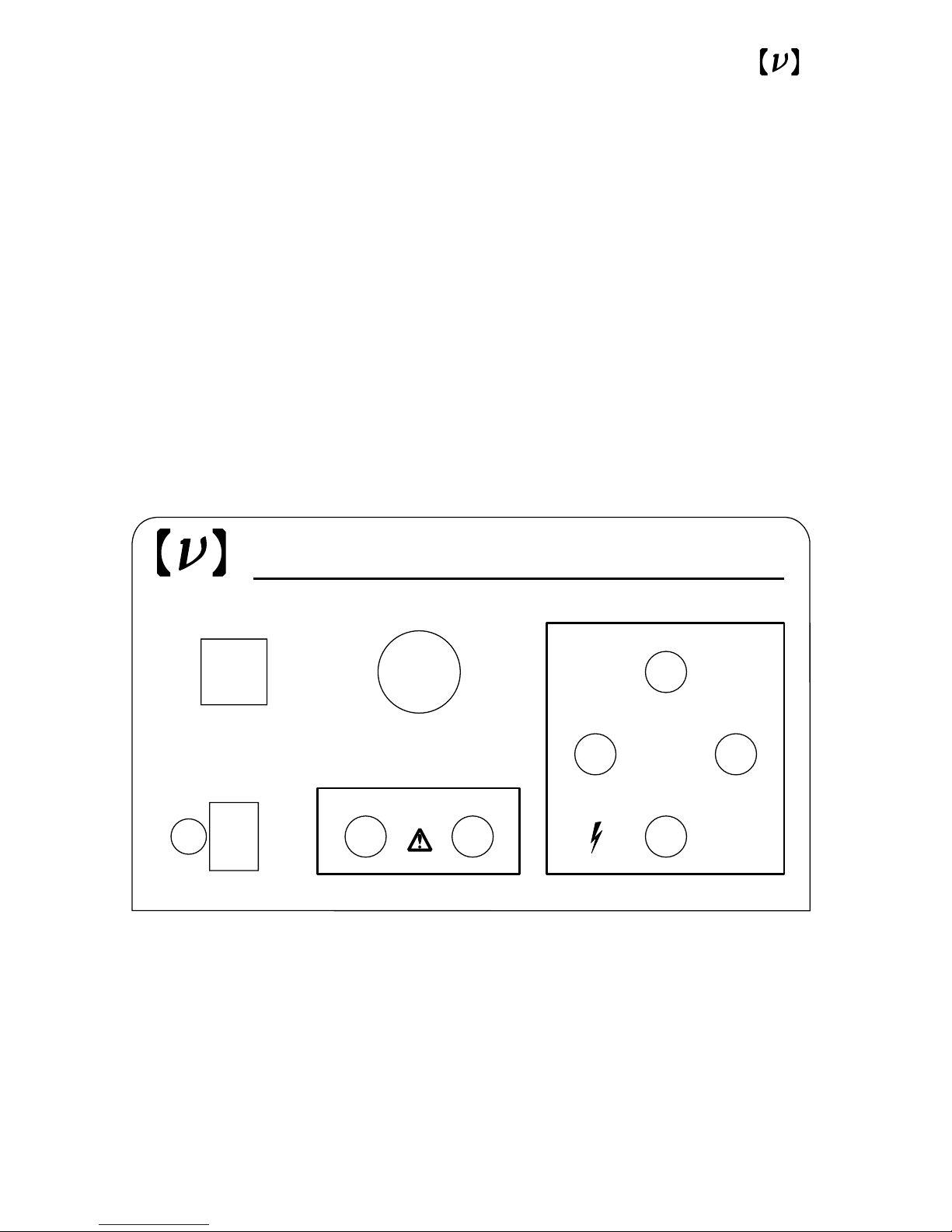
The DC offset is adjustable from the front-panel
potentiometer, and Input 1 and Input 2 come from
the front-panel BNC jacks. The outputs consist of a
high-voltage output, a monitor output (which is
high-voltage output/30, or 1.5 times the sum of
the inputs), a +200 V DC current-limited output
and a -200 V DC current-limited output.
NOTE: Before connecting the AC power cable, verify the the line voltage setting in the amplifier
agrees with the local voltage. (See Appendix 2:
Operating Voltages & Fuses.)
Page 7
7
Fig. 1
Block diagram of the Model 3211
High-voltage Amplifier.
G
DC Offset
0
G
1
Input 1
G
1
Input 2
G
2
+
G
2
Current
Limit
+200 V Out
High-Voltage
Output
Current
Limit
-200 V Out
Monitor
-200 V
+200 V
High-Voltage
On/Off
Switch
Switch
Page 8

The ±200 V outputs (nominally ±212 V) are
designed to be used as bias voltages for electrooptic modulators or piezo-electric transducers.
They are current limited at DC (with 2-mA maximum DC out), but at higher frequencies act as an
AC return.
The front-panel BNC inputs can be used independently or together in a summing configuration.
The input resistance is 5.75 kΩand the output
resistance is 25 Ω. The total gain from input to
output is +40 and the maximum output voltage is
200 V. The maximum input voltage is therefore
±5 V for linear operation. The absolute maxi-
mum voltage at Input 1 and Input 2 without damage is ±10 V peak.
NOTE: OPERATING PRECAUTIONS
The high-voltage operational amplifier in the
Model 3211 can be permanently damaged if thermally stressed. Thermal stress occurs only if the
unit is operated well into its current-limited mode
for at least 5–10 minutes; the unit is adequately
protected for all other conditions. To avoid the possibility of overheating the amplifier and reducing
its lifetime, you should ensure that it doesn’t operate in the current-limited mode for more than a
couple of minutes. The amplifier will operate in
this mode under certain combinations of peak
voltage, frequency, and load capacitance. Please
refer to the Appendix 1: Bandwidth Limitations for
a discussion on calculating the frequency at which
current limiting occurs given the load capacitance
and the signal’s peak voltage.
8
Page 9
9
Fig. 2
Front panel view of the Model 3211 Amplifier.
Power
Input 1 Input 2 High Voltage Output
-200 V +200 V
Monitor
DC Offset
High Voltage
On/Off
Made in U.S.A.
High-Voltage Amplifier
NEW FOCUS, Inc. • Mountain View, California, 94041
3211
Do not exceed 10 V peak on inputs
Outputs
Caution: Up to 200 V
Page 10

The Model 3211 was designed primarily to drive
electro-optic modulators and piezo-electric
transducers. However, you can use it as a generalpurpose amplifier to drive any capacitive load less
than 100 nF. The amplifier can be used in conjunction with a low-voltage source to create a
broad-bandwidth, low-voltage modulator driver.
To prevent undesirable external signals from
appearing on the High-voltage Output, the user
should terminate any unused inputs.
10
Applications
Page 11
11
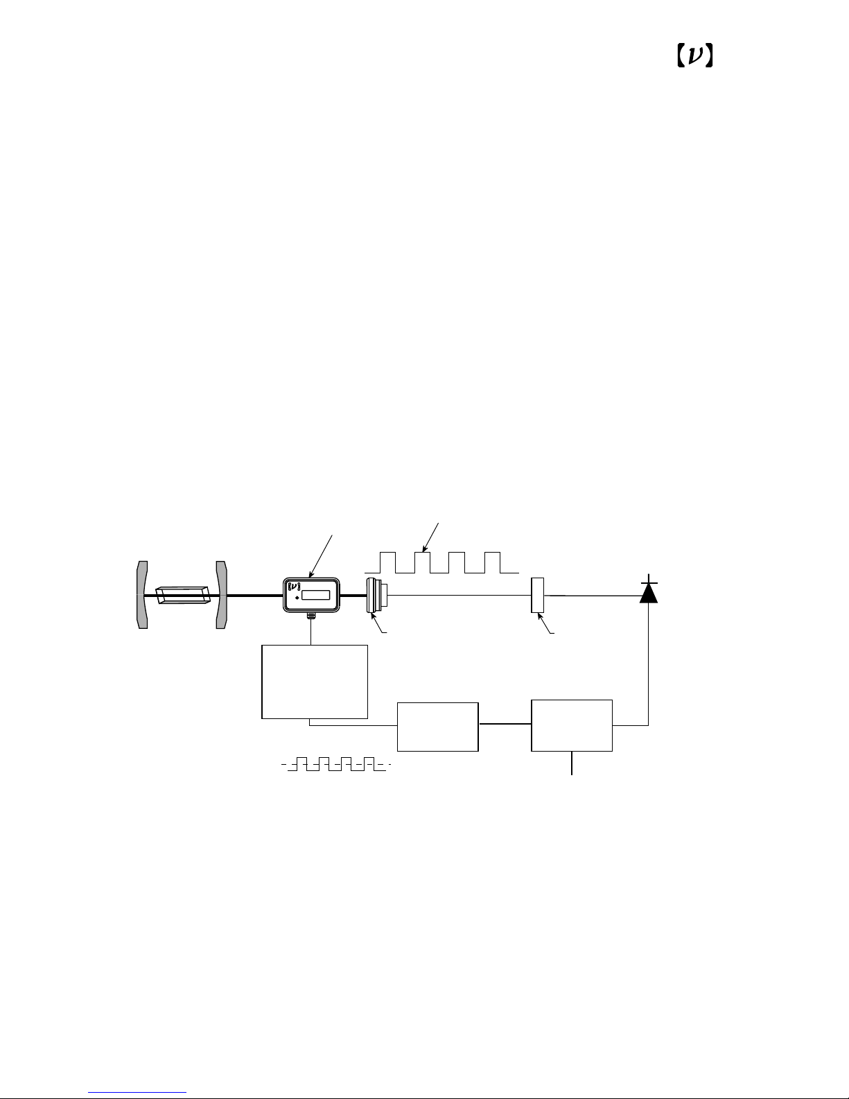
Fig. 3
Driving an electro-optic amplitude modulator
with the Model 3211 Amplifier.
Sample
Lock-in
Amplifier
Function
Generator
±5 V
V= ±200 V
Signal Out
0-1 MHz
Optically-Chopped
Signal
Amplitude
Modulator
Models 1801,
1811, 2001,or 2001
Photoreceivers
Feussner
Polarizer
484X
YYY Phase Modulator
NEW FOCUS Inc. Mountain View, CA
Model 3211
High-voltage
Amplifier
Laser
Page 12

Appendix 1:
Bandwidth
Limitations
When driving capacitive loads with a high-voltage
amplifier, such as the Model 3211, there are several
factors which determine the bandwidth of the system.
Closed-Loop Bandwidth
The closed-loop bandwidth of the high-voltage
operational amplifier in the Model 3211 determines the maximum bandwidth attained by the
Model 3211; this bandwidth is at least 1 MHz.
Other factors, such as slew rate, current limiting
and RC filtering can limit the bandwidth even further, as described below.
Slew Rate
The slew rate of the Model 3211 is at least 700 V/µs.
Thus, the maximum frequency of operation is
dependent on the peak voltage. With a peak voltage
of 200 V, the maximum frequency, and therefore
the largest signal bandwidth, is given by:
V
out=Vp
sin(2πft)
dV
out
/dt=2πfVpcos(2πft)<700 V/µs
f
max
(large signal)=111×10
6
/Vp,
where V
p
is the peak voltage, f is the frequency in
Hz, t is time, and V
out
is the output voltage.
Therefore, when the peak voltage is 200 V and the
amplifier is not current limited as described in the
section below, the maximum frequency on the
high-voltage output is 555 kHz.
12
Page 13

13
Current Limit
The maximum current that can be provided by the
amplifier Model 3211 is 120 mA. For this reason,
when driving capacitive loads, the maximum
frequency is capacitance dependent. The displacement current drawn by a capacitor is given by:
I=CdV/dt<0.12 A
dV/dt
max
=2πfV
p
.
Therefore,
f
max
(current limit)~0.0191/CVp.
If the peak voltage into the capacitor is 200 V, then
the maximum frequency (in Hz) is given by:
f
max
(current limit/large signal)~9.55x10⁻⁵/C.
Therefore, if the capacitive load is 100 nF (0.1 µF),
the maximum frequency before current limiting
begins to distort a 200-V waveform is 955 Hz.
RC Filter
The Model 3211 has an output resistance of
approximately 25 Ω. This resistance, along with
the capacitive load, forms a low-pass, RC filter with
the 3-dB point at a frequency of 1/(2πRC). This
RC filter can limit the bandwidth performance of
the Model 3211 for large capacitive loads and very
small peak voltages.
Summary
When determining the maximum bandwidth of
the Model 3211 for a known capacitive load and a
desired peak voltage, the user must calculate the
bandwidth determined by the slew rate (dominates
Page 14

14
for small—on the order of 100 pF or less—capacitive loads and large voltages), the current limit
(dominates for large—on the order of tens of
nanofarads—capacitive loads) and the RC filter
(dominates for large capacitive loads and very
small peak voltages). The smallest of the 1-MHz
closed loop bandwidth, the calculated slew-rate
limited bandwidth, the calculated current-limitedbandwidth, and the calculated RC bandwidth
determines the maximum bandwidth of the
Model 3211. Four examples illustrating how to
determine the maximum bandwidth follow.
Example 1 (slew-rate-limited case)
Peak voltage=200 V
Load capacitance=10 pF
1.Slew-rate-limited bandwidth:
111 MHz/200=555 kHz
2.Current-limited bandwidth:
0.0191/(10x10
-12
×200)=9.55 MHz
3.Closed-loop bandwidth: 1 MHz
4.RC bandwidth: 1/(2π×25×10x10
-12
)=637 MHz
Therefore, the maximum bandwidth is the smallest of the four, or 555 kHz.
Example 2 (current-limited case)
Peak voltage=200 V
Load capacitance=100 nF
1.Slew-rate-limited bandwidth:
111 MHz/200=555 kHz
2.Current-limited bandwidth:
0.0191/(100x10
-9
×200)=955 Hz
Page 15

15
3.Closed-loop bandwidth: 1 MHz
4.RC bandwidth: 1/(2π×25×100x10
-9
)=63.7 kHz
Therefore, the maximum bandwidth is the smallest of the four, or 955 Hz.
Example 3 (closed-loop-bandwidthlimited case)
Peak voltage=100 V
Load capacitance=100 pF
1.Slew-rate-limited bandwidth:
111 MHz/100=1.11 MHz
2.Current-limited bandwidth:
0.0191/(100x10
-12
×100)=1.91 MHz
3.Closed-loop bandwidth: 1 MHz
4.RC bandwidth:
1/(2π×25×100x10
-12
)=63.7 MHz
Therefore, the maximum bandwidth is the smallest of the four, or 1 MHz.
Example 4 (RC-bandwidth-limited case)
Peak voltage=1 V
Load capacitance=100 nF
1.Slew-rate-limited bandwidth:
111 MHz/1=111 MHz
2.Current-limited bandwidth:
0.0191/(100x10
-9
×1)=191 kHz
3.Closed-loop bandwidth: 1 MHz
4.RC bandwidth: 1/(2π×25×100x10
-9
)=63.7 kHz
Therefore, the maximum bandwidth is the smallest of the four, or 63.7 kHz.
Page 16
16
Appendix 2:
Operating
Voltages
and Fuses
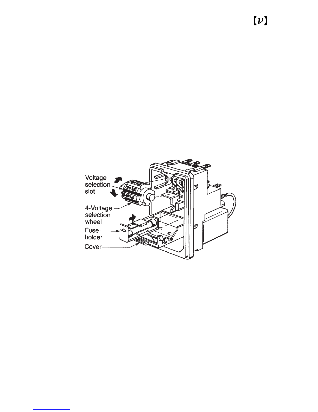
The Model 3211 can operate from 100, 120, 220, or
240 V AC with AC frequencies of 47–63 Hz. The
unit is configured at the factory for the standard
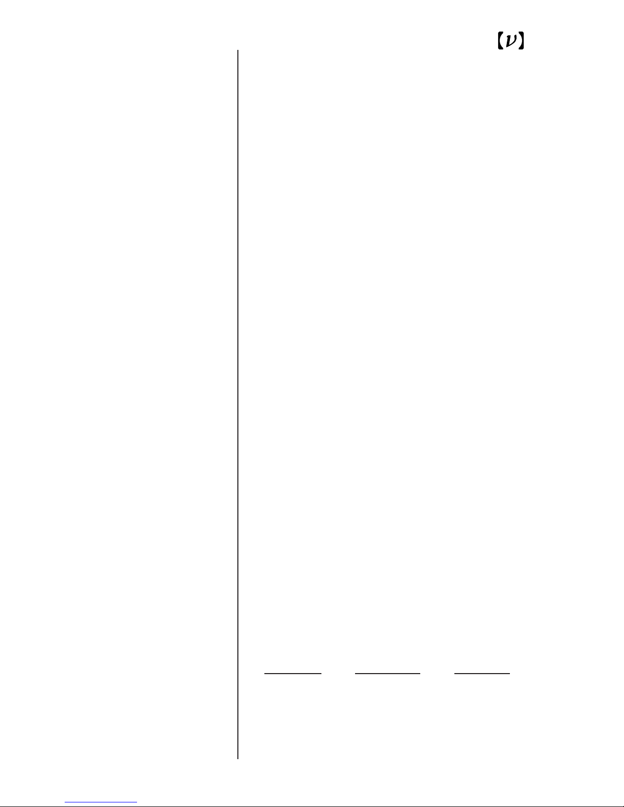
AC voltage in the user’s country. To select a different operating voltage, please refer to Fig. 4 and follow the directions below:
1.Disconnect the power cord.
2.Open the cover of the power entry module on
the rear panel with a small blade screwdriver or
similar tool.
3.Insert the tool into the voltage selection slot and
remove the wheel from the unit.
4.Turn the wheel and re-insert into the module so
the desired voltage is shown.
NOTE: Do not attempt to rotate the wheel while it
is still in the power entry module; the wheel must
be removed, turned, and then re-inserted.
5.Close the cover.
6.Verify that the proper voltage is showing through
the module’s window.
The power entry module requires two 5x20-mm,
slow-blow fuses, such as Littlefuse’s
®
Slo-Blo®239
Series: one for the hot line and the other for the
neutral line. Replacement fuses should be as follows:
AC V
oltage Fuse Rating Little Fuse
100 V AC 1.6 A 239 01.6
120 V AC 1.6 A 239 01.6
220 V AC 0.8 A 239.800
240 V AC 0.8 A 239.800
Page 17
17
Fig. 4
Model 3211 Amplifier voltage selection.
Page 18

Performance
Bandwidth, 3 dB(C<100 pF) 1 MHz
Slew Rate 700 V/µs
Output Voltage ±200 V
Voltage Gain 40
Input Impedance 5.75 kΩ
Output Impedance 25 Ω
Max. Load Capacitance 0.1 µF
Max. Output Current 120 mA
Max. Input without Damage ±10 V peak
Operating AC Voltage 100, 120, 220, or
240 V AC
Specifications
18
Page 19

19
Warranty
New Focus guarantees its products to be free of
defects for one year from the date of shipment.
This is in lieu of all other guarantees, expressed or
implied, and does not cover incidental or consequential loss.
Technical Support
Information and advice about the operation of
your New Focus products are available from our
technical support engineers.
Engineers are on duty from 8:00–5:00 PST,
Monday through Friday (excluding holidays). For
quickest response, ask for "Technical Support" and
know the model number for your product.
Phone: (408) 980-8088
Fax: (408) 980-8883
Support is also available by email.
Email: [email protected]
We typically respond to email within one business day.
Service
In the event that your amplifier malfunctions or
becomes damaged, please contact New Focus for a
return authorization number and instructions on
shipping the unit back for evaluation and repair.
Warranty,
Service, &
Support
 Loading...