

Page 1

Models 2001 and 2011
User’s Manual
Front-End Optical Receivers
Page 2

2
200110 Rev. B
Is a registered trademark of
New Focus, Inc.
Page 3

Contents
Warranty
Introduction
Theory
Operation
Appendix 1:
Optical Input
Appendix 2:
Electrical Output
Specifications
3
4
6
14
16
16
19
Warranty
New Focus, Inc. guarantees its products to be
free of defects for one year from the date of shipment. This is in lieu of all other guarantees,
expressed or implied, and does not cover incidental or consequential loss.
3
Page 4

4
Introduction
With the New Focus front-end optical receivers you
can measure optical signals conveniently and
accurately. These photoreceivers are optimized for
versatility and efficient operation. New Focus offers
two different models to match your wavelength
requirements; Table 1 lists each model’s characteristics and specifications. Both models have
adjustable high- and low-pass filters as well as a
90-dB adjustable electronic gain range to allow
shot-noise-limited detection at almost any
optical power level from 1 µW to 10 mW. The
DC÷30 setting prevents your signal from going
off-scale due to DC-amplitude fluctuations.
Model 2001 has a noise equivalent power (NEP)
of less than 1 pW/√Hz from 400 nm to 1060 nm
on the 10
4
scale. Model 2011 has an NEP of less
than 0.5 pW/√Hz from 800 nm to 1600 nm on the
10
4
scale. Both models maintain a static current
drain of less than 1 mA which allows a pair of 9-V
batteries to operate for at least 500 hours.
Page 5

Model Number 2001 2011
Wavelength Range 400–1060 nm 800–1600 nm
Photodiode Material Silicon InGaAs
Photodiode Size 0.81 mm
2
0.09 mm
2
5
Table 1
Characteristics of the
Front-end Optical Receivers.
Page 6

6
Theory
A block diagram of Models 2001 and 2011 is
shown in Figure 1. The photoreceiver consists of a
photodiode followed by a transimpedance amplifier, two adjustable filters, and a final gain multiplier (Fig. 1). The responsivity of the silicon photodiode for the Model 2001 is shown in Fig. 2. The
response factor (V/mW) which is a calibration
term that converts measured electrical power to
incident optical power at a specific wavelength is
shown in Fig. 3 for the Model 2001. The optical
power striking the photodetector is equal to the
voltage measured divided by the product of the
gain knob setting, multiplier factor (1 or 3) and
the wavelength response factor. (see Appendix 1:
Optical Input for a specific example.) Figs. 4 and 5
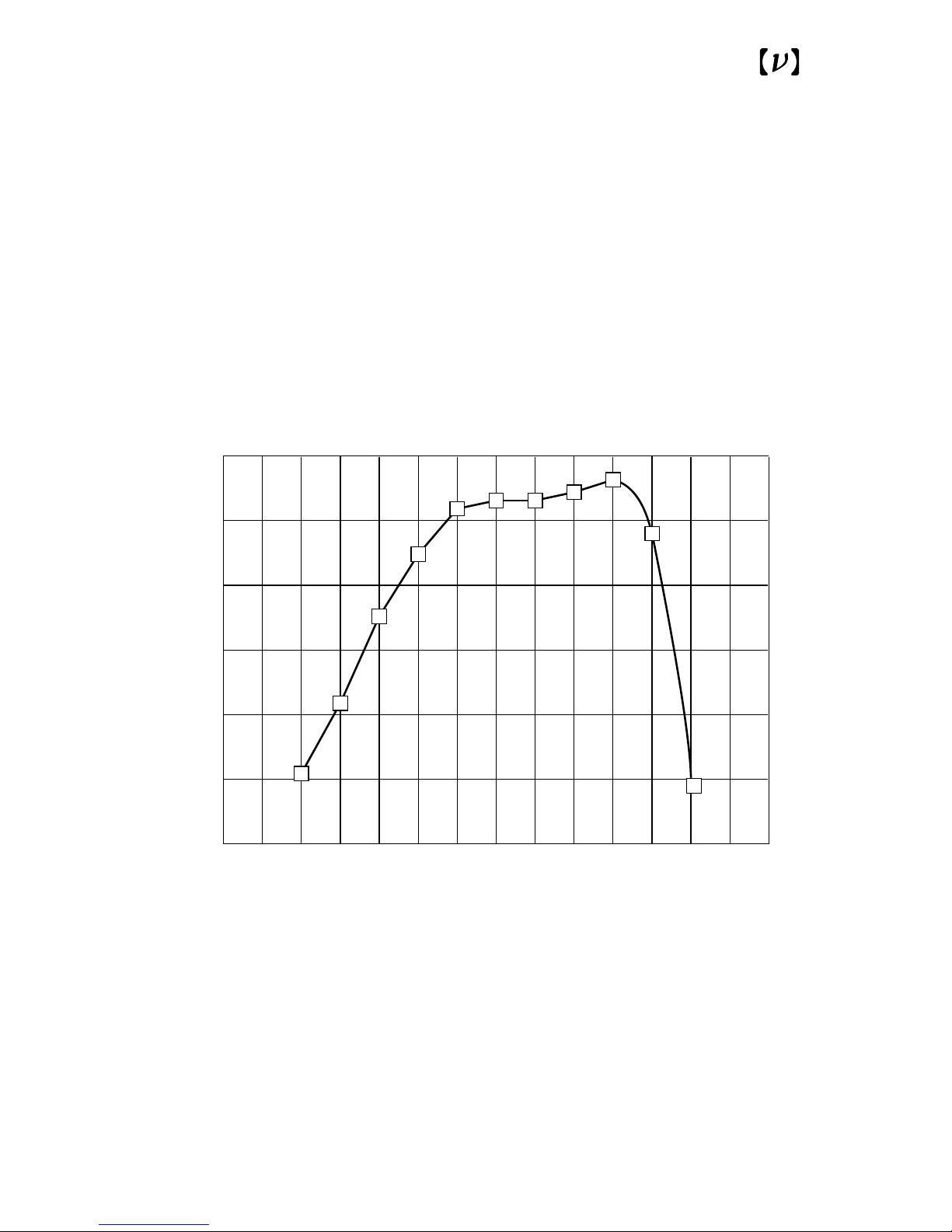
show the responsivity and response factor for the
InGaAs photodetector in the Model 2011.
The noise performance of the Models 2001 and
2011 is determined by the setting of the first stage
while the final gain stage simply scales the signal
for ease of viewing. The NEP is the amount of
optical input power required for the output signal
to just equal the output noise of the optical receiver. It is a measure of the weakest optical signal and
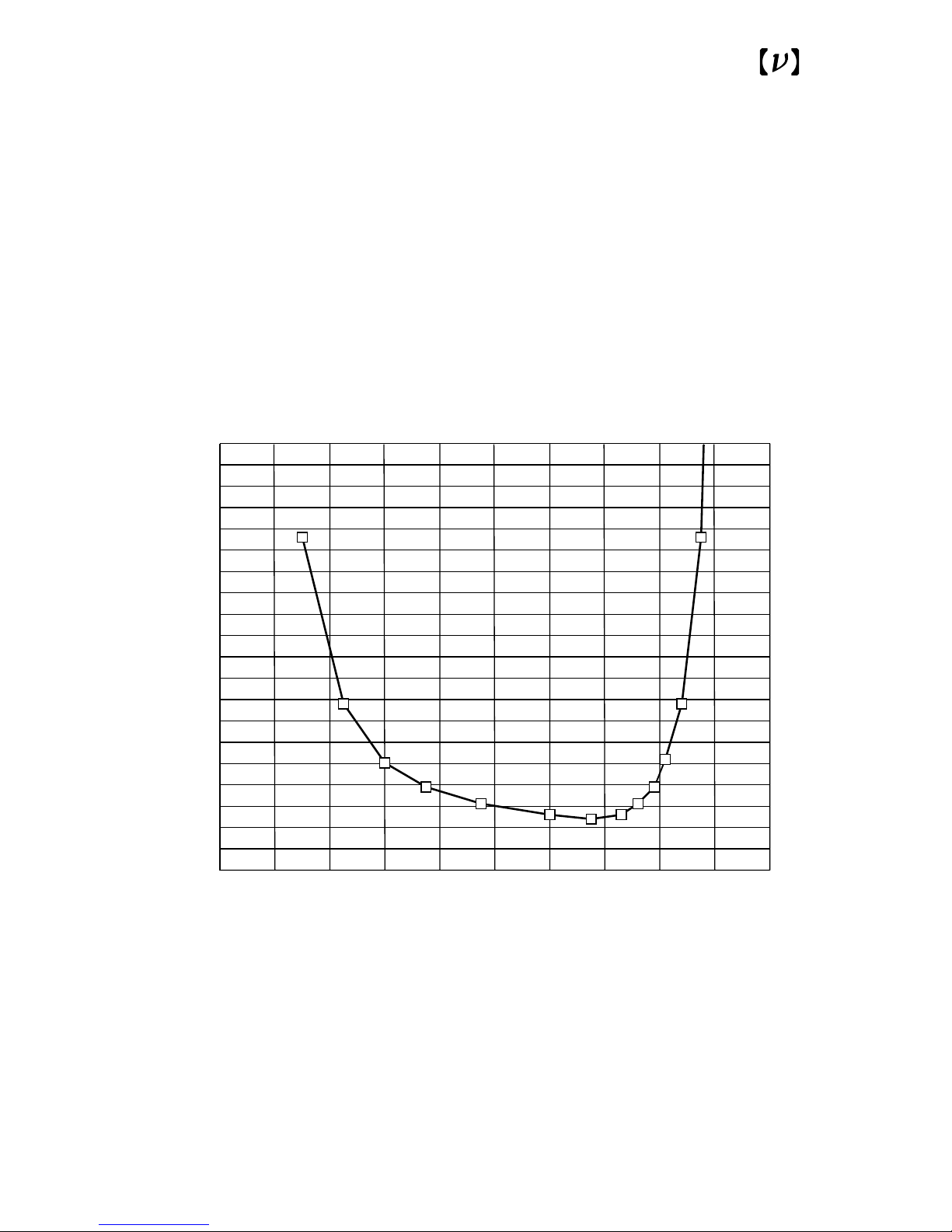
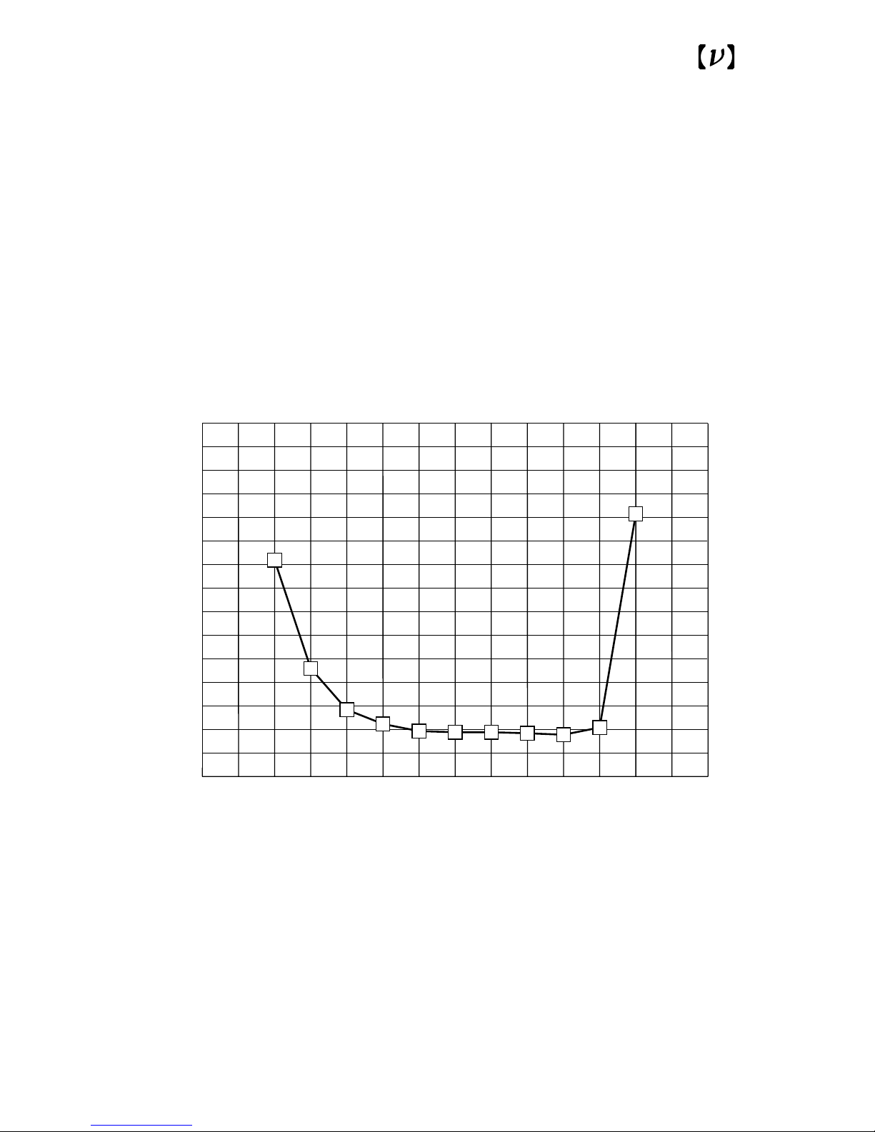
is a function of the wavelength. The NEP as a
function of wavelength on the 10
4
gain setting is
shown in Fig. 6 for Model 2001 and in Fig. 7 for
Model 2011. The NEP increases by a factor of
approximately three for each full clockwise turn of
the gain knob.
Both the photodiode and the circuit are powered
from a ±9-V supply provided by two 9-V alkaline
batteries.
Page 7
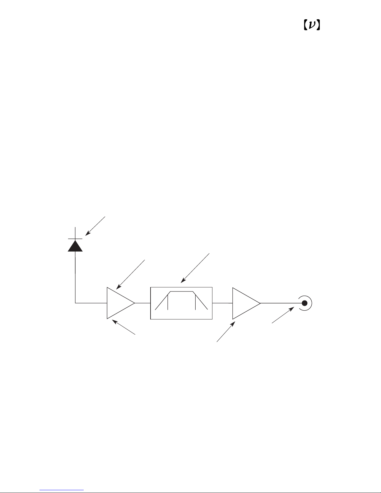
Fig. 1
Functional block diagram of the
front-end optical receiver photoreceivers.
Photodiode
Adjustable
gain stage
10,000
1,000
100
10
1
Independently adjustable
6-dB/octave high- and
low-pass filters
with <90° phase shift
f
L
f
H
Low-noise
transimpedance
amplifier
Gain multiplier:
3
1
SMA output
7
Page 8
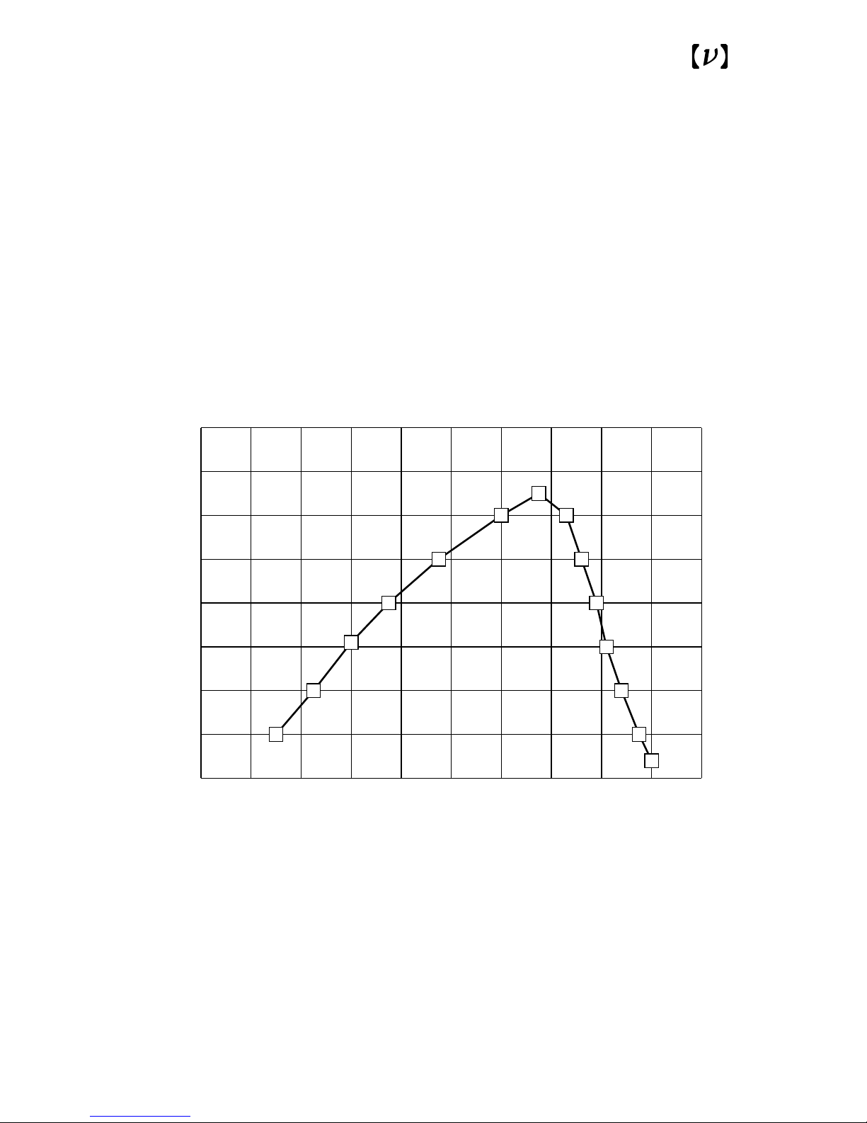
8
Fig. 2
Responsivity of Model 2001.
200 400 600 800 1000 1200
0.0
0.2
0.4
0.6
0.8
Wavelength (nm)
Responsivity (A/W)
Page 9
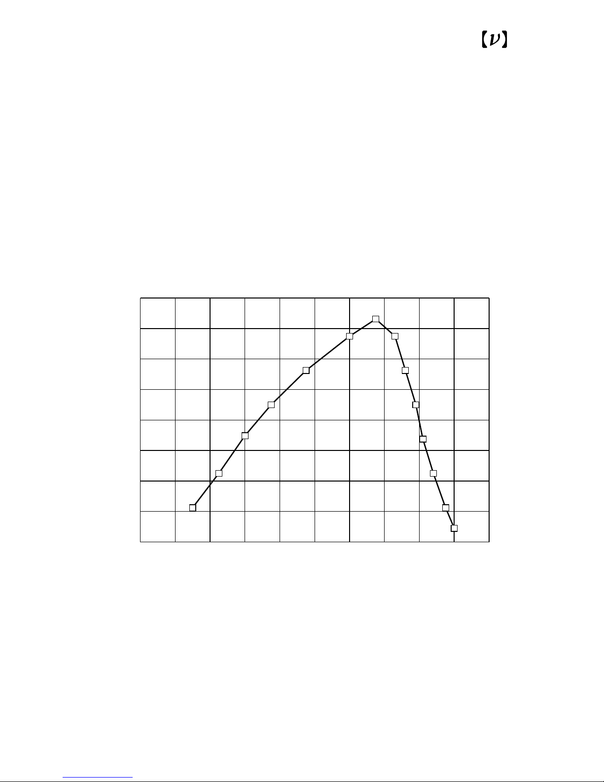
Fig. 3
Response factor versus wavelength
for the Model 2001.
200 400 600 800 1000 1200
0.0
0.1
0.2
0.3
0.4
Wavelength (nm)
Response Factor
9
Page 10
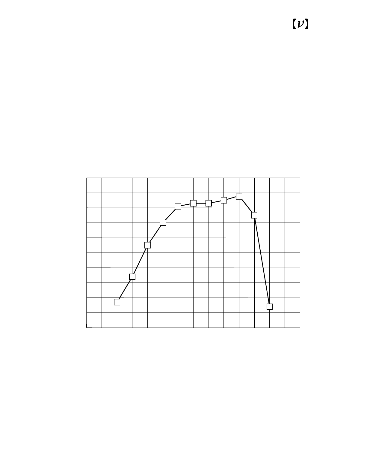
10
Fig. 4
Responsivity of the Model 2011
600 800 1000 1200 1400 1600 1800 2000
0.0
0.2
0.4
0.6
0.8
1.0
Wavelength (nm)
Responsivity (A/W)
Page 11
11
Fig. 5
Response factor versus wavelength for the Model 2011
Wavelength (nm)
Response Factor
600 800 1000 1200 1400 1600 1800 2000
0.0
0.1
0.2
0.3
0.4
0.5
0.6
Page 12
12
Fig. 6
NEP as a function of wavelength for
Model 2001 (at 10
4
Gain Setting).
200 400 600 800 1000 1200
0.0
0.5
1.0
1.5
2.0
Wavelength (nm)
NEP (pW/ Hz)
Page 13
13
Fig. 7
NEP as a function of wavelength for
Model 2011 (at 10
4
Gain Setting).
Wavelength (nm)
NEP (pW/ Hz)
600 1000 1400 1800
0.0
0.5
1.0
1.5
Page 14

14
Operation
To check the two batteries:
1.Turn on the photoreceiver using the power
switch.
2.Set the Low Frequency Adjust knob to DC.
3.Set the Gain knob to 10
4
×3 setting.
4.Focus at least 100 µW of optical power on the
detector (or place the detector in front of a desk
lamp).
The output should be greater than 7 V. If it is
not, replace the batteries with fresh ones.
To replace the batteries:
The photoreceivers are shipped with two fresh 9-V
batteries installed. To avoid confusion about how
much life is left in the batteries, replace the batteries on a monthly basis when the unit is in frequent
use.
1.Turn off the photoreceiver using the power
switch.
2.Use a Phillips head screw driver to remove the
two screws on the back panel of the photoreceiver (see the figure in the Specifications).
3.Remove the back panel.
4.Replace the used 9-V batteries with fresh ones.
5.Replace the back panel and the two screws.
6.Recheck the battery level as described above.
Page 15

15
Tuning the position and frequency of the
optical output:
1.Use the 8-32 (M4) tapped hole located on the
base of the photoreceiver to mount it on an
adjustment positioning device for alignment of
the optical spot on the photodetector diode located on the back side of the unit.
2.Position the mounted photoreceiver in front of
the focusing lens.
A simple 25-mm focal length biconvex singlet
should be adequate for most applications.
3.Turn on the optical beam.
4.Connect the SMA port on the front of the pho-
toreceiver to a voltmeter.
5.Align the detector to the beam until the output
peaks on the voltmeter.
6.Adjust the gain for optimal performance:
Refer to the discussion in Appendix 2: Electrical
Output.
• Set the Low Frequency Adjustment knob to DC.
• Set the Gain knob to the full clockwise position.
• Set the Multiplier to “×1”.
• Turn the Gain knob clockwise to increase it until
you measure approximately 2 V on the voltmeter.
Page 16

16
Appendix 1:
Optical Input
The optical input power striking the photodetector
is equal to the measured voltage divided by the
product of the gain knob setting times the multiplier [1 or 3] times the wavelength response factor.
For example, with these settings:
Gain knob: 10
4
Gain multiplier: ×3
Response factor: 0.25 Volts/mW
DC output voltage : 2 V.
The optical input power therefore is equal to
2 V/(10
4
×3×0.25)=270 nW.
Appendix 2:
Electrical Output
The photoreceiver has three knobs: a low-frequency corner, a high-frequency corner and a gain
knob, as well as a gain-multiplier switch.
Frequency Knobs
The upper left knob adjusts the low-frequency corner and the upper right knob adjusts the high-frequency corner. The corner frequency is the frequency where the response is down by 3 dB from
its mid-band value. Fig. 8 depicts the frequency
response with a roll-off at 6 dB/octave below the
low corner and above the high corner. To obtain
Page 17

signals over the full bandwidth, set the low cornerfrequency knob to its full counterclockwise position and set the high corner-frequency knob to its
full clockwise position. The corner frequency
increases by a factor of three with each full clockwise turn. The photoreceivers have ten settings for
each frequency corner, creating a wide variety of
frequency responses. If the low-frequency corner is
set higher than or equal to the high-frequency corner, there will be significant attenuation at all frequencies.
In addition, the low-frequency knob has a DC÷30
setting. This is a convenient setting for observing a
small AC signal on a widely varying DC component. It will prevent your signal from going offscale due to DC amplitude fluctuations.
Note: With the most sensitive gain setting (10
4
)
the maximum bandwidth is reduced to 20 kHz.
Gain Knob
The overall gain is the product of the gain knob
setting and the wavelength response factor (V/mW)
indicated on the front of the unit. You can increase
the gain by a factor of three by setting the Gain
Multiplier Switch to “×3.”
17
Page 18
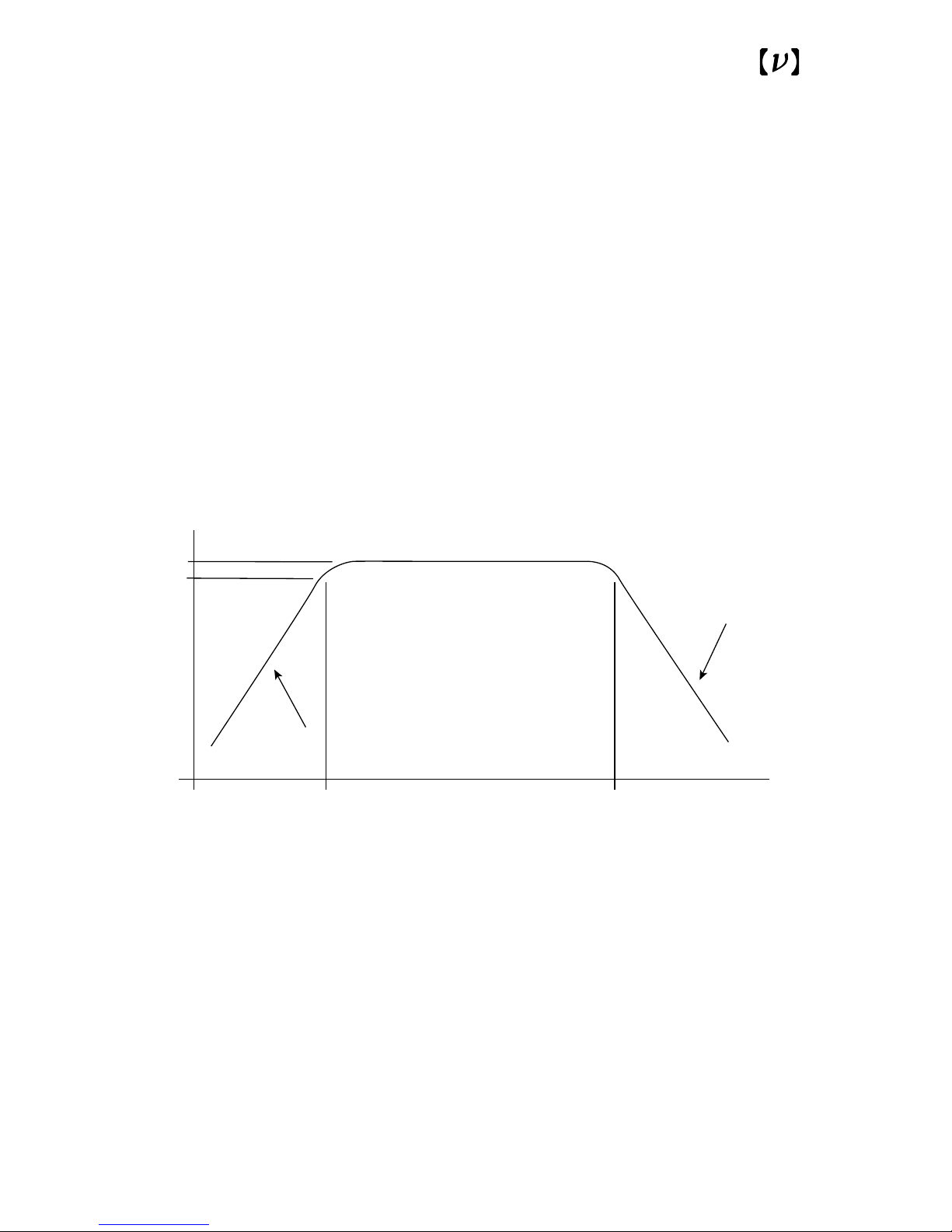
Fig. 8
Setting the frequency response of the
Front-end Optical Receivers
0
-3
Response (dB)
Roll-off
6 dB/octive
Roll-off
6 dB/octive
Log (frequency)
f
L
f
H
18
Page 19
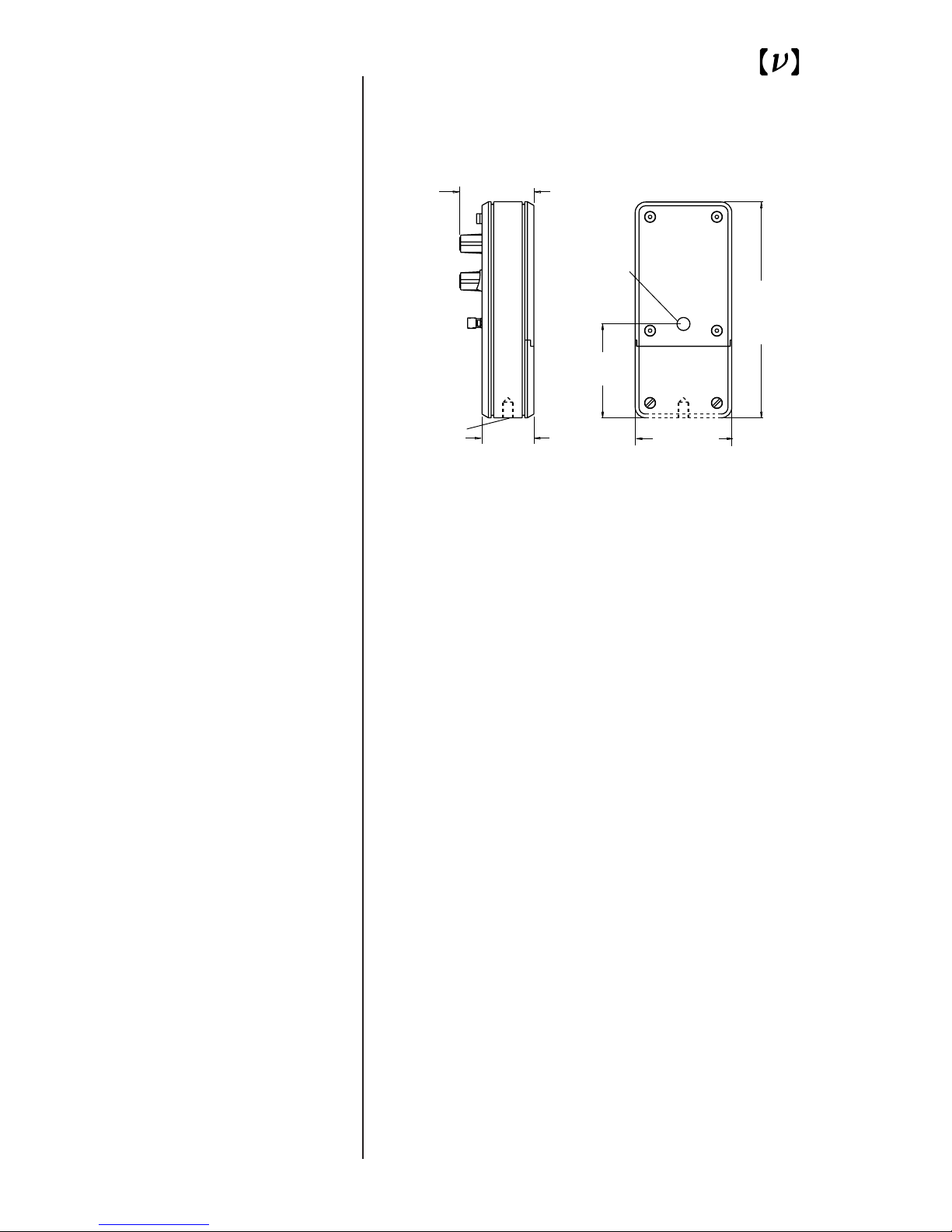
Specifications
Dimensional
Performance
Model 2001
Model 2011
Responsivity Peak: 0.6 A/W
Conversion Gain Peak: 1.1x10
7
V/W
NEP (on the 10
4
scale): 1.0 pW/√Hz
Responsivity Peak: 0.8 A/W
Conversion Gain Peak: 1.5x10
7
V/W
NEP (on the 10
4
scale): 0.5 pW/√Hz
Accuracy
Absolute: 20%
Range to Range Consistency: 5% from 10
4
to 10
3
2% at other settings
Frequency Response: User definable from
DC to >100 kHz on
most gain settings
Photodetector
2.25 (57.1)
5.17
(131.2)
1.24 (31.5)
2.31 (58.6)
8-32 (M4) Thd
1.78 (45.2)
19
Page 20

20
 Loading...