

Page 1
USER’S GUIDE
12-GHz Amplified
Photoreceivers
Model 1580-A
These photoreceivers are sensitive to electrostatic
discharges and could be permanently damaged if
subjected even to small discharges. Ground yourself adequately prior to handling these receivers or
making connections. A ground strap provides the
most effective grounding and minimizes the
likelihood of electrostatic damage.
5215 Hellyer Ave. • San Jose, CA 95138-1001 • USA
phone: (408) 284–6808 • fax: (408) 284–4824
e-mail: [email protected] • www.newfocus.com
Page 2

Warranty
New Focus, Inc. guarantees its products to be free of defects for one year from
the date of shipment. This is in lieu of all other guarantees, expressed or implied,
and does not cover incidental or consequential loss.
Information in this document is subject to change without notice.
Copyright 2002, 2001–1998, New Focus, Inc. All rights reserved.
The and logos and NEW FOCUS, Inc. are
registered trademarks of NEW FOCUS, Inc.
Document Number 158001 Rev. A
Page 3

Contents
Operation 5
Introduction . . . . . . . . . . . . . . . . . . . . . . . . . . . . . . . . . . . . . . . . . . . 5
Handling Precautions . . . . . . . . . . . . . . . . . . . . . . . . . . . . . . . . . . . 6
Connecting the Power Supply and Bias . . . . . . . . . . . . . . . . . . 6
Microwave connection and set-up . . . . . . . . . . . . . . . . . . . . . . . 7
Connecting the Receiver to the Optical Input. . . . . . . . . . . . . 8
Characteristics 9
Photoreceiver Characteristics. . . . . . . . . . . . . . . . . . . . . . . . . . . . 9
Bias-Monitor Characteristics . . . . . . . . . . . . . . . . . . . . . . . . . . . 10
Responsivity . . . . . . . . . . . . . . . . . . . . . . . . . . . . . . . . . . . . . . . . . . 10
Troubleshooting 11
Testing the Photodiode . . . . . . . . . . . . . . . . . . . . . . . . . . . . . . . . 11
Checking the DC-Offset Voltage . . . . . . . . . . . . . . . . . . . . . . . .11
Basic Optical Test. . . . . . . . . . . . . . . . . . . . . . . . . . . . . . . . . . . . . . 12
Customer Service 13
Technical Support . . . . . . . . . . . . . . . . . . . . . . . . . . . . . . . . . . . . . 13
Service . . . . . . . . . . . . . . . . . . . . . . . . . . . . . . . . . . . . . . . . . . . . . . . . 13
Appendix I: Microwave Connectors 15
Appendix II: Inside the Photoreceiver 16
12-GHz Photoreceivers Contents • 3
Page 4

4 • Contents NEW FOCUS, Inc.
Page 5
Operation
Introduction
High-speed measurements down to a few microwatts
are easy with the Model 1580-A amplified
photoreceiver. This module converts optical signals to
electronic signals, in effect, giving any high-speed/
high-frequency instrument in your lab an optical
input. The small size of the module allows you to
connect it directly to your test instrument, eliminating
the need to follow the photoreceiver with coaxial
cable, which can seriously distort picosecond pulses
and attenuate microwave signals.
In earlier “low-frequency” models, Models 1580-LF, we
used an external DC block to achieve low-frequency
cutoffs of 10 kHz. In the current “-A” versions, we
eliminated the external blocking capacitor, achieving
the 10-kHz cutoff with an internal capacitor.
The Model 1580-A uses a GaAs PIN photodiode
designed for high responsivity in the 780–870-nm
wavelength range. The internal 62.5-µm multimode
fiber which delivers light to the photodiode permits
the use of input fibers with cores of 62.5 µm or smaller,
including single-mode fibers. The high-speed amplifier
which follows the photodiode produces a clean impulse
response with minimal ringing, making the Model
1580-A ideal for digital communication
measurements.
The Model 1580-A has a negative conversion gain due
to the inverting amplifier used. If you are using an
12-GHz Photoreceivers Operation • 5
Page 6
oscilloscope and you want a positive output, use the
scope’s inverting x(-1) function.
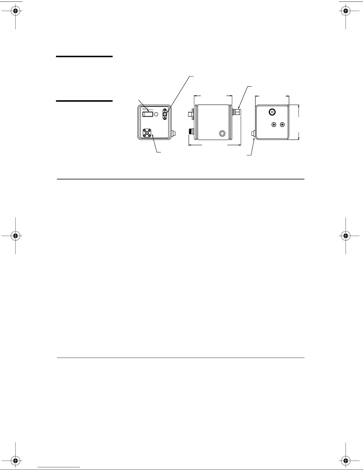
Figure 1:
Model 1580-A
photoreceiver
module
Power switch
Off On
Optical Input
Batt
Chk
Bias
Monitor
FC/PC connector
for fiber optic input
Handling Precautions
Whenever handling the photoreceiver, make sure to
follow these precautions:
• Prior to handling the detector or making
Bias-monitor port—output
is equal to photodiode current
times 1000 Ω, for 1 mV/µA.
Output K-connector
2.25 (57.1)
3.14 (79.8)
Power
connector
2.00 (50.8)
2.00
(50.8)
connections, be sure to ground yourself
adequately—even small electrostatic discharges
could permanently damage the detector. A ground
strap provides the most effective grounding and
minimizes the likelihood of electrostatic damage.
• Do not over torque the microwave K-connector.
Excessive torque can damage connectors.
• Make sure the optical connector is clean and
undamaged before connecting it to the detector
module.
Connecting the Power Supply and Bias
1.
Prior to handling the detector, ground yourself
with a grounding strap to prevent electrostatic
damage to the receiver.
6 • Operation NEW FOCUS, Inc.
Page 7
2.
Connect the power cable to the power supply. Two
power cables were included with the receiver; use
the appropriate cable for your power supply.
Connecting to a New Focus power supply:
the cable with the two round microconnectors.
Connect one end of the cable to one of the power
supply’s 300-mA outputs.
Connecting to another power supply:
cable with the round microconnector on one end
and three banana plugs on the other end. Be
careful to connect the banana plugs to the power
supply as follows; connect the red plug to a wellregulated, +15-V, 200-mA source; connect the
black plug to a -15-V, 200-mA source; connect the
green plug to the common ground of the two
sources.
3.
Connect the bias-monitor port to a voltmeter and
observe the voltage level on the voltmeter. This
voltage is the DC offset plus dark current. This
Use
Use the
dark voltage should be less than 5 mV.
Note:
Note:
If you are coupling light into a fiber, use the voltmeter to
monitor the photocurrent to help optimize the coupling.
Microwave Connection and Set-up
1.
Connect the photoreceiver module’s microwave
connector to a test instrument that has a 50-Ω
input, such as an oscilloscope or spectrum analyzer, or to another 50-Ω load. If necessary, use a
high-frequency cable (best performance is
achieved without a cable).
2.
To avoid connector damage and signal distortion,
be sure that the cable and the instrument you
intend to connect to the module have compatible
connectors. See “Appendix I: Microwave
12-GHz Photoreceivers Operation • 7
Connectors” on page 15 for a list of compatible
connectors.
Page 8

Connecting the Receiver to the Optical Input
1.
Before connecting the input fiber to the photoreceiver, measure the power in the fiber to ensure it
is within the safe operating range. For a pulsed
input, determine the maximum (peak) power.
You may want to use the New Focus Model 2011FC 200-kHz Photoreceiver for this purpose; it has
a higher maximum pulse power, and has the
sensitivity to aid in fiber alignment.
2.
Connect the fiber-optic cable to the fiber-optic
input.
8 • Operation NEW FOCUS, Inc.
Page 9
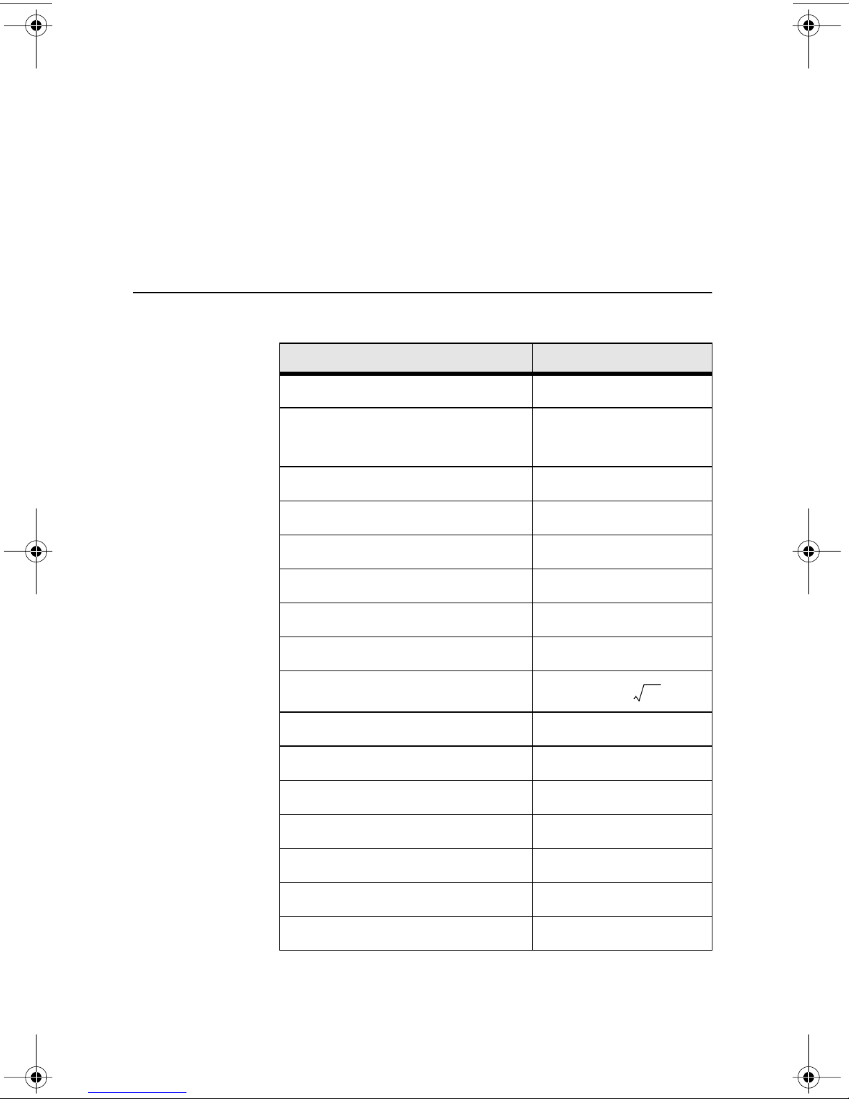
Characteristics
Hz
Photoreceiver Characteristics
Model # 1580-A
Wavelength Range 400–870 nm
3-dB Bandwidth
(electrical)
Low-Frequency Cutoff 10 kHz
Rise Time 34 ps
Conversion Gain –400 V/W
Responsivity 0.4 A/W
Transimpedance Gain 1000 V/A
Output Impedance 50
Noise Equivalent Power (NEP)
cw Saturation Power 1.5 mW
Maximum Pulse Power 1.5 mW
Detector Material/Type GaAs/PIN
12 GHz (typical)
10 GHz (minimum)
Ω
50 pW/
Values taken at 850 nm.
12-GHz Photoreceivers Characteristics • 9
Input Fiber 62.5-µm multimode
Optical Input Connector FC/PC
Electrical Output Connector Wiltron K
Power Requirements ±15 V, 200 mA
Page 10
Bias-Monitor Characteristics
Model # 1580-A
DC Gain 1 mV/µA
DC Offset (max.) 5 mV
Output Impedance 10 k
Bandwidth 50 kHz
Responsivity
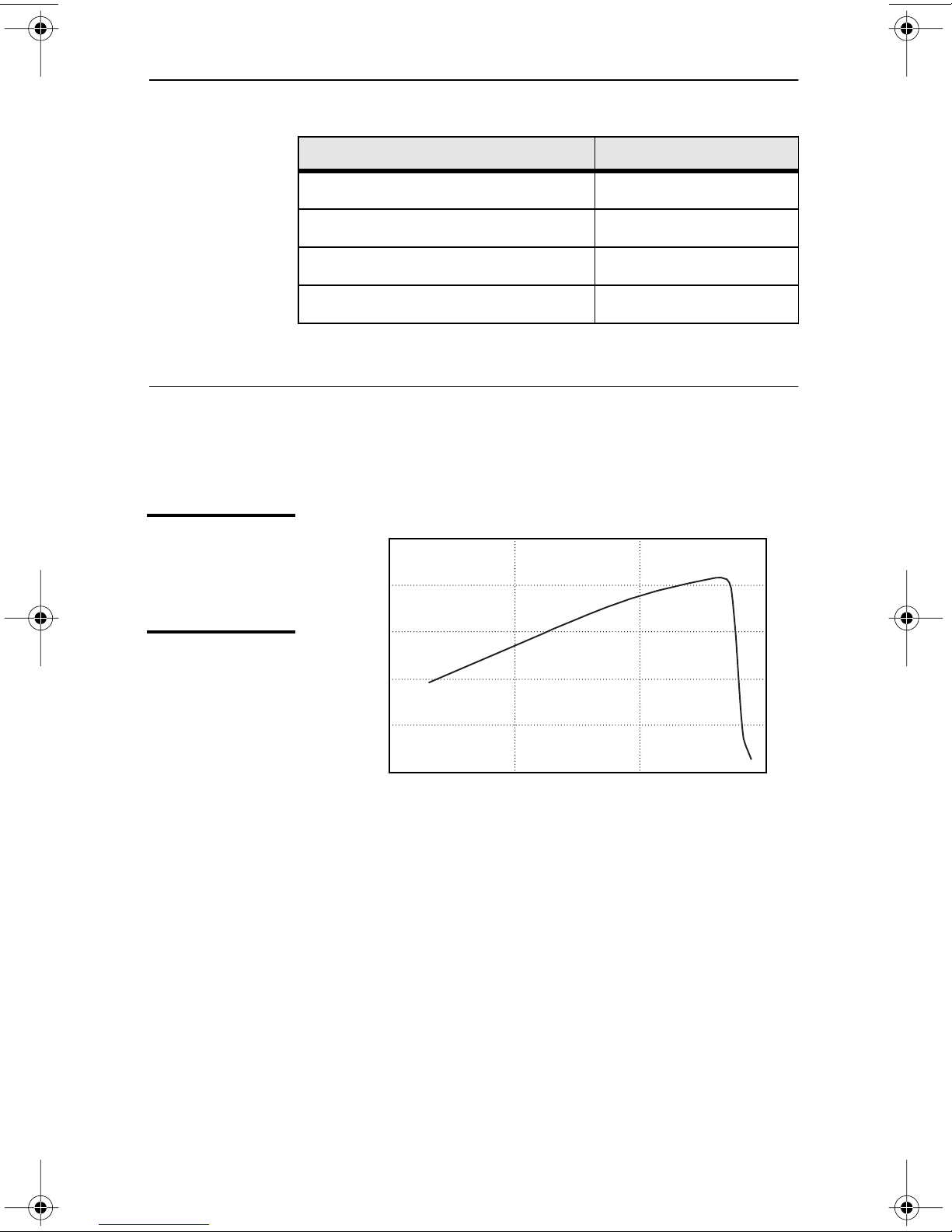
Figure 2:
Responsivity vs.
wavelength for
Model 1580-A
Ω
A graph of the typical and predicted responsivity of
the Model 1580-A is shown below.
0.5
0.4
0.3
0.2
Responsivity, A/W
0.1
10 • Characteristics NEW FOCUS, Inc.
0
700600 800 900
Wavelength, nm
Page 11
Troubleshooting
Testing the Photodiode
The photodiode can be damaged by electrostatic
discharge or excessive optical power, which can lead to
an increased dark (or
photodiode can result in a degraded responsivity and
frequency/impulse response. See “Checking the DCOffset Voltage,” below.
Other problems, such as a damaged amplifier, are
more difficult to diagnose. If the response from your
receiver is lower than you expect, contact New Focus
to arrange for a repair (see “Customer Service” on
page 13).
offset
) voltage. A damaged
Checking the DC-Offset Voltage
1.
With no light on the photodetector, turn the
detector on.
2.
Use a voltmeter to measure the Bias Monitor
output voltage. This voltage is the DC offset plus
3.
12-GHz Photoreceivers Troubleshooting • 11
dark current.
If the output is >5 mV, then the detector is
probably damaged and will need to be returned to
New Focus.
If the output is <5 mV, then perform the Basic
Optical Test described below.
Page 12

Basic Optical Test
To quickly test the photodiode in your receiver, run
this simple DC optical test.
1.
Turn the receiver on.
2.
Using a voltmeter or oscilloscope, measure the
output voltage from the Bias Monitor on the front
panel of the bias supply.
With no light on the detector, the Bias Monitor
voltage should be <5 mV.
3.
Illuminate the photodetector.
4.
With the voltmeter or oscilloscope, you should
observe a DC output voltage.
If you know the optical power and wavelength,
you can calculate the expected output voltage
) using the expression:
(
V
out
P
is the input optical power (watts), R is the
in
V
=
P
out
• R • G, where
in
photodetector’s responsivity (A/W, see page 10),
and G is the amplifier’s transimpedance gain (V/A).
The gain of the bias monitor port is 1000 V/A.
If the output voltage is low, then contact New Focus to
arrange for a repair (see “Customer Service” on
page 13).
12 • Troubleshooting NEW FOCUS, Inc.
Page 13
Customer Service
Technical Support
Information and advice about the operation of any
New Focus product is available from our applications
engineers. For quickest response, ask for “Technical
Support” and know the model and serial numbers for
your product.
Service
Hours:
Toll Free:
Phone:
Support is also available by fax and email:
Fax:
Email:
We typically respond to faxes and email within one
business day.
In the event that your photoreceiver malfunctions or
becomes damaged, please contact New Focus for a
8:00–5:00 PST, Monday through Friday
(excluding holidays).
1-866-NUFOCUS (1-866-683-6287)
(from the USA & Canada only)
(408) 284-6808
(408) 980-8883
return authorization number and instructions on
shipping the unit back for evaluation and repair.
12-GHz Photoreceivers Customer Service • 13
Page 14

14 • Customer Service NEW FOCUS, Inc.
Page 15
Appendix I: Microwave Connectors
The performance you obtain from the Model 1580-A
photoreceiver depends largely on the instruments you
use to measure their outputs and how the connections
are made to the instruments.
Connect the male connector of the photoreceiver
directly to the female connector of the instrument.
(For the low-frequency version, be sure to include a DC
block between the receiver and the instrument.)
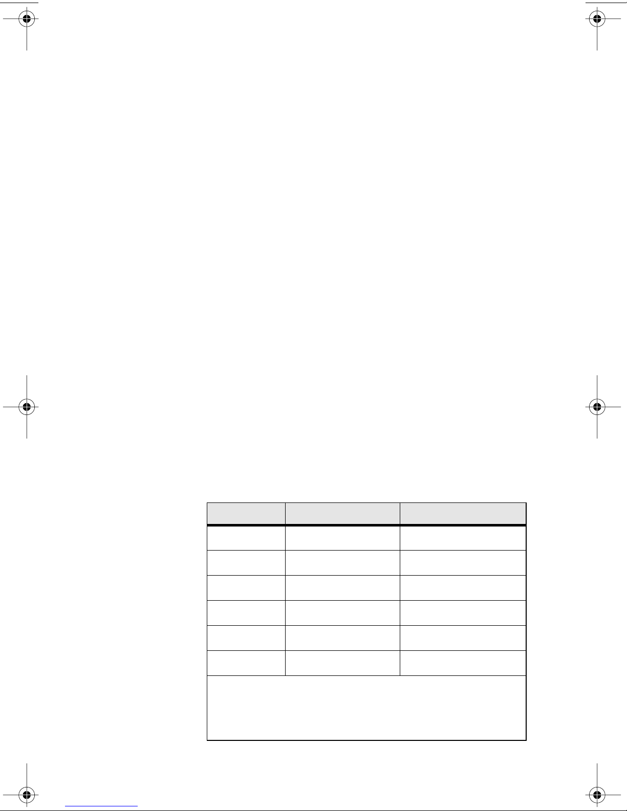
If you need to use an adapter, make sure it is designed
for your frequency range of interest. The following
table lists a few connectors and the frequency ranges in
which they may be used. For more information,
request Application Note 1. If you use an intervening
coaxial cable, select a cable with sufficiently low loss in
the frequency range of interest.
Connector Frequency Range Compatibility
BNC DC–2 GHz ——
SMA DC–18 GHz Wiltron K, 3.5 mm
3.5 mm DC–34 GHz SMA, Wiltron K
Wiltron K DC–40 GHz SMA, 3.5 mm
2.4 mm DC–55 GHz Wiltron V
Wiltron V DC–65 GHz 2.4 mm
New Focus also offers the following adapters:
Model 1225 Male-SMA to Female-BNC
Model 1226 Female-SMA to Male-BNC
Model 1227 40-GHz Flex Cable, Female-K to Male-K
12-GHz Photoreceivers Appendix I: Microwave Connectors • 15
Page 16
Appendix II:
Inside the Photoreceiver
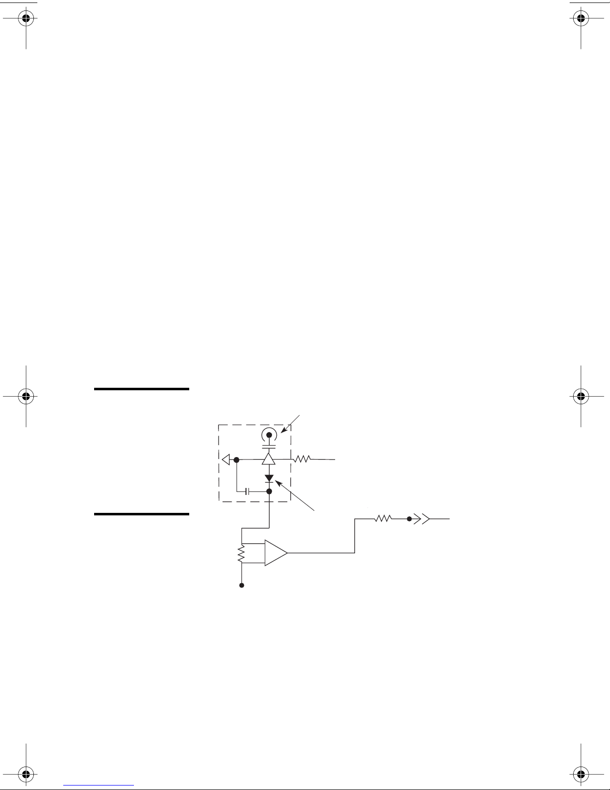
A gold-plated microwave housing inside the
photoreceiver module contains the high-frequency
circuitry. This housing is bolted to a printed-circuit
board which regulates the bias for the photodiode and
amplifies the DC photocurrent for the monitor port.
The optical signal is brought from the front-panel
connector to the microwave housing with 62.5-µmcore multimode fiber.
Figure 3:
Simplified
schematic of
the Model
1580-A
photoreceiver
module
Microwave
Housing
Instrumentation
Amp
+
V
Microwave
Output
Connector
Photodiode
+
V
Bias Monitor
16 • Appendix II: Inside the Photoreceiver NEW FOCUS, Inc.
 Loading...