

Page 1
USER’S GUIDE
15-GHz & 25-GHz
Photodetectors
Models 1480 & 1481
Includes Model 1481-50
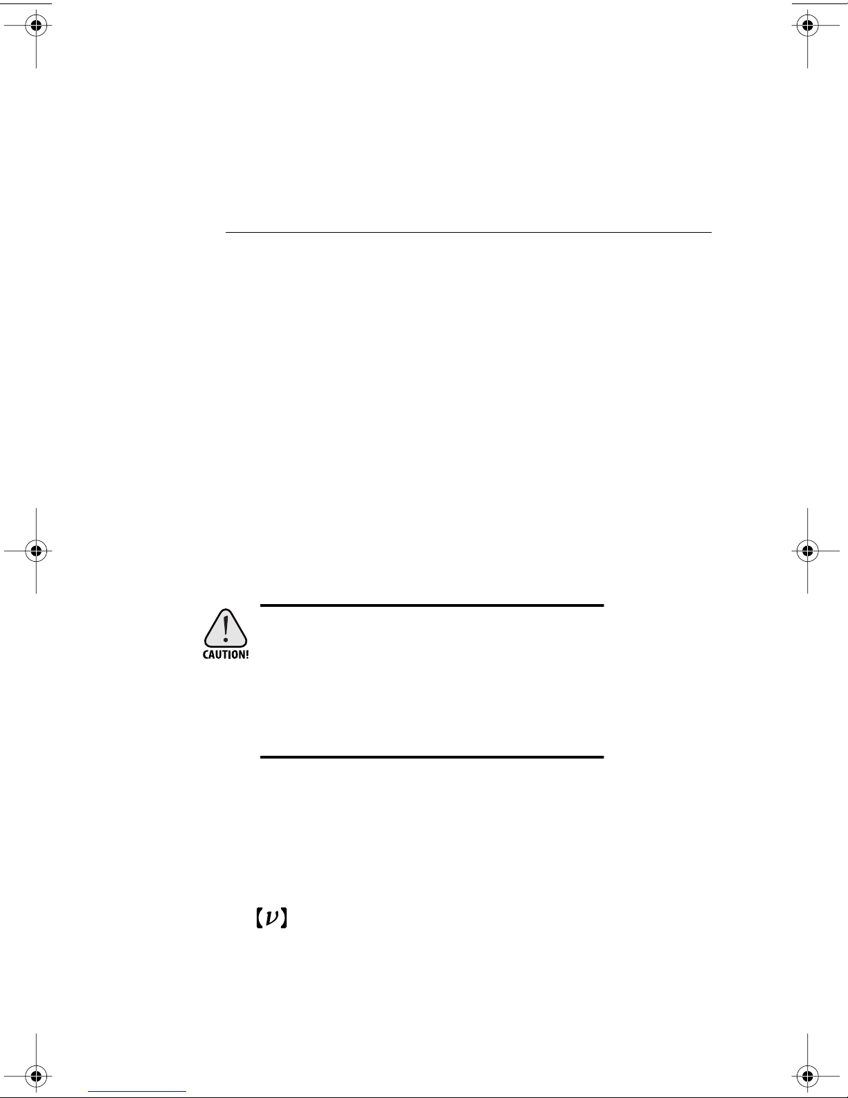
These photodetectors are sensitive to electrostatic
discharges and could be permanently damaged if
subjected even to small discharges. Ground yourself adequately prior to handling these detectors or
making connections. A ground strap provides the
most effective grounding and minimizes the
likelihood of electrostatic damage.
2630 Walsh Ave.• Santa Clara, CA 95051-0905• USA
phone: (408) 980-8088 • Fax: (408) 980-8883
e-mail: [email protected] • www.newfocus.com
NEW FOCUS, Inc.
®
®
Page 2

Warranty
New Focus, Inc. guarantees its products to be free of defects for one year from
the date of shipment. This is in lieu of all other guarantees, expressed or implied,
and does not cover incidental or consequential loss.
Copyright 2000, New Focus, Inc. All rights reserved.
The symbol and NEW FOCUS, Inc. are registered trademarks
of NEW FOCUS, Inc.
Document Number 151095 Rev. A
Page 3

Contents
Operation 5
Introduction . . . . . . . . . . . . . . . . . . . . . . . . . . . . . . . . . . . . . . . . . . . 5
Handling Precautions. . . . . . . . . . . . . . . . . . . . . . . . . . . . . . . . . . . 6
Quick Start. . . . . . . . . . . . . . . . . . . . . . . . . . . . . . . . . . . . . . . . . . . . . 7
Checking the Battery and Offset Voltage . . . . . . . . . . . . . . . . . 8
Making the Microwave Connection. . . . . . . . . . . . . . . . . . . . . . 9
Connecting the Detector to the Optical Input . . . . . . . . . . . . 9
Characteristics 11
Photodetector Characteristics . . . . . . . . . . . . . . . . . . . . . . . . . . 11
Bias-Monitor Characteristics . . . . . . . . . . . . . . . . . . . . . . . . . . . 12
Responsivity . . . . . . . . . . . . . . . . . . . . . . . . . . . . . . . . . . . . . . . . . . 12
Troubleshooting 13
Testing the Photodiode . . . . . . . . . . . . . . . . . . . . . . . . . . . . . . . . 13
Checking the DC-Offset Voltage. . . . . . . . . . . . . . . . . . . . . . . . 13
Basic Optical Test. . . . . . . . . . . . . . . . . . . . . . . . . . . . . . . . . . . . . . 13
Cleaning the Fiber Connector . . . . . . . . . . . . . . . . . . . . . . . . . . 14
Customer Service 17
Technical Support . . . . . . . . . . . . . . . . . . . . . . . . . . . . . . . . . . . . . 17
Service. . . . . . . . . . . . . . . . . . . . . . . . . . . . . . . . . . . . . . . . . . . . . . . . 17
Appendix I: Microwave Connectors 19
Appendix II: Inside the Photodetector 20
15-GHz & 25-GHz Photodetectors Contents • 3
Page 4

4 • Contents NEW FOCUS, Inc.
Page 5

Operation
Introduction
High-speed measurements are easy with the Models
1480 and 1481 photodetector modules. These
modules convert your optical signals to electronic
signals, in effect giving every high-speed/highfrequency instrument in your lab an optical input.
Each module connects directly to the test instrument
or amplifier, eliminating the need for coaxial cables,
which could seriously distort picosecond pulses and
attenuate microwave signals. The optical signal is
delivered to the photodiode in the module through a
multimode optical fiber. Moreover, the photodiode
bias circuit and battery are self-contained, eliminating
the hassle of external power supplies and expensive
bias networks and reducing the possibility of
photodiode damage due to overvoltage.
The Models 1480 and 1481 use a GaAs PIN photod iode
designed for high responsivity in the 780–870-nm
wave length range. The high-speed circuitry produces a
clean impulse response, making these models ideal for
digital communication measurements. A 50-Ω
terminating resistor minimizes electrical reflections,
which helps to minimize ringing when used with
amplifiers which may not have perfect 50-Ω inputs.
The Model 1480 has an internal 62.5-µm multimode
fiber which delivers the input light to the 65-µmdiameter photodiode, permitting the use of delivery
fibers with core diameters of 62.5 µm or smaller,
15-GHz & 25-GHz Photodetectors Operation • 5
Page 6
including single-mode fibers. The internal fiber is
angle polished for low back reflection.
The Model 1481 has an internal single-mode fiber,
which is angle polished to reduce ba ck re flections. The
Model 1481-50 has an internal 50-µm multimode fiber
and uses a GRIN lens to image the fiber output onto
the 25-µm photodiode used in these models. The
optical elements are anti-reflection coa ted fo r lo w back
reflection at 850 nm.
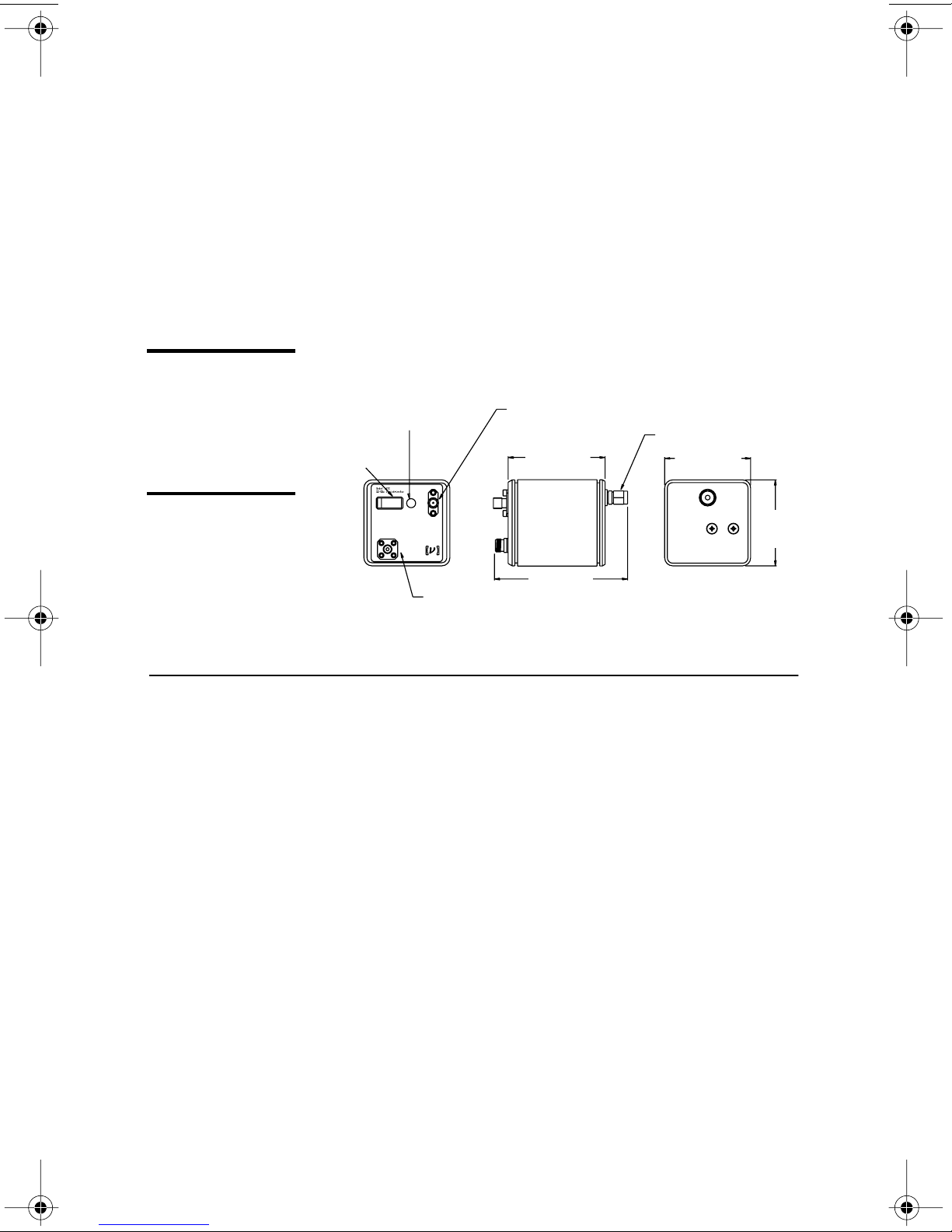
Figure 1:
Models
1480 & 1481
photodetector
Battery-check button—
press to apply the photodiode bias voltage to
the bias-monitor port.
Power switch
modules
Batt
Off On
Chk
Bias
Optical Input
Monitor
FC/PC connector
for fiber optic input
Handling Precautions
Whenever handling the photoreceiver, make sure to
follow these precautions:
• Prior to handling the detector or making
Bias-monitor port—output
is equal to photodiode current
times 1000 Ω, for 1 mV/µA.
Output K-connector
2.25 (57.1)
3.14 (79.8)
2.00 (50.8)
2.00
(50.8)
• Do not over torque the microwave K-connector.
• Make sure the optical connector is clean and
6 • Operation NEW FOCUS, Inc.
connections, be sure to ground yourself
adequately—even small electrostatic discharges
could permanently damaged the detector. A
ground strap provides the most effective
grounding and minimizes the likelihood of
electrostatic damage.
Excessive torque can damage connectors.
undamaged before connecting it to the detector
module.
Page 7

Quick Start
Use the Models 1480 and 1481 high-speed GaAs
photodetector modules for detecting light in the
wave len gth range from 400 t o 870 nm. Each module is
50-Ω terminated and has an internal battery and bias
circuitry to make it self-contained—no additional
power supply or bias circuitry is needed.
To operate the module, follow these quick-start
instructions or consult the other sections of this
manual for more detail.
1.
Take proper precautions to avoid electrostatic
damage to the photodiode. (See “Handling Precautions” on page 6.)
2.
Remove the module from its case.
3.
Turn on power using the “Off/On” switch.
If you are using the detector for the first time, or you
wish to check the batt ery and DC offset, perform steps
4, 5 and 6
4.
Connect a voltmeter to the “Bias Monitor” SMA
connector.
5.
Press the “Batt Chk” button. The voltage should be
at least 3.5 V.
6.
Release the “Batt Chk” button. Without an optical
input, the voltage should be less than 10 mV.
7.
Connect the photodetector module to your
measurement instrument, being careful not to
over -torque the K -connecto r. The instrument must
have a 50-Ω input impedance.
8.
Check that the optical power emerging from your
fiber is below the cw Saturation Power, as
15-GHz & 25-GHz Photodetectors Operation • 7
appropriate, to ensure detector linearity and to
avoid detector damage. (See “Characteristics” on
page 11.)
Page 8

9.
Connect y our o p tical fiber to the co nnecto r on the
detector module.
10.
When finished using the module, turn off the
power to preserve battery life.
If any of these steps present problems or you would
like more information, please consult the remainder of
this manual.
Checking the Battery and Offset Voltage
The battery and offset voltage should be checked
regularly to ensure proper functioning of the detector.
1.
Turn on the module using the power switch.
2.
Connect the “Bias Monitor” port to a voltmeter.
3.
Press and hold the “Batt Chk” button and observe
the bias-monitor output. The photodiode bias
voltage is momentarily applied to the “Bias
Monitor” SMA connector . A read in g o f 5 V on this
connector is typical with a new battery; the
battery should be replaced when the voltage
reaches 3.5 V.
4.
Release the “Batt Chk” button and observe the
voltage level on the voltmeter. Without an optical
input, this voltage is the DC offset plus dark
current. This “dark voltage” should be less than
10 mV.
5.
If needed, keep the voltmeter connected to the
module to optimize coupling to the fiber.
Replacing the battery
1.
Turn off the module and remove the two screws
2.
3.
8 • Operation NEW FOCUS, Inc.
on the back panel with a Phillips screwdriver. (See
Figure 1 on page 6.)
Remove the back panel and replace the battery.
Replace the back panel.
Page 9

4.
Check the battery level as described above.
Making the Microwave Connection
1.
Connect the photoreceiver module’s microwave
connector to a test instrument that has a 50-Ω
input, such as an oscilloscope or spectrum analyzer, or to another 50-Ω load. If necessary, use a
high-frequency cable (best performance is
achieved without a cable).
2.
To avoid connector damage and signal distortion,
be sure that the cable and the instrument you
intend to connect to the module have compatible
connectors. See “Appendix I: Microwave
Connectors” on page 19 for a list of compatible
connectors.
Connecting the Detector to the Optical Input
1.
Measure the peak power in the fiber prior to connection to the module to be sure it is within the
safe operating range (see “Photodetector Characteristics” on page 11).
2.
Connect the fiber-optic cable to the fiber-optic
input on the detector module. If needed, the Bias
Monitor may be used to optimize coupling to the
fiber.
15-GHz & 25-GHz Photodetectors Operation • 9
Page 10

10 • Operation NEW FOCUS, Inc.
Page 11

Characteristics
Hz
Photodetector Characteristics
The values below are given at 850 nm.
Model # 1480 1481
Wavelength Range 400–870 400–870
3-dB Bandwidth 15 GHz 25 GHz
Rise Time 25 ps 15 ps
Conversion Gain 10 V/W 10 V/W
Responsivity 0.4 A/W 0.4 A/W
Output Impedance 50
Minimum NEP
cw Saturation Power >5 mW >2 mW
Detector Material/Type GaAs/PIN GaAs/PIN
Detector Diameter 65 µm 25 µm
Input-Fiber Core Diameter
“-50” version
Power Requirements Internal 9-V battery Internal 9-V battery
Optical Input Connector FC/PC FC/PC
Electrical Output Wiltron K Wiltron K
45 pW/ 45 pW/
62.5-µm multimode
N/A
Ω
Hz
50
Ω
9-µm single mode
50-µm multimode
15-GHz & 25-GHz Photodetectors Characteristics • 11
Page 12
Bias-Monitor Characteristics
Model # 1480 1481
DC Gain 1 mV/µA 1 mV/µA
DC Offset (max.) 10 mV 10 mV
Responsivity
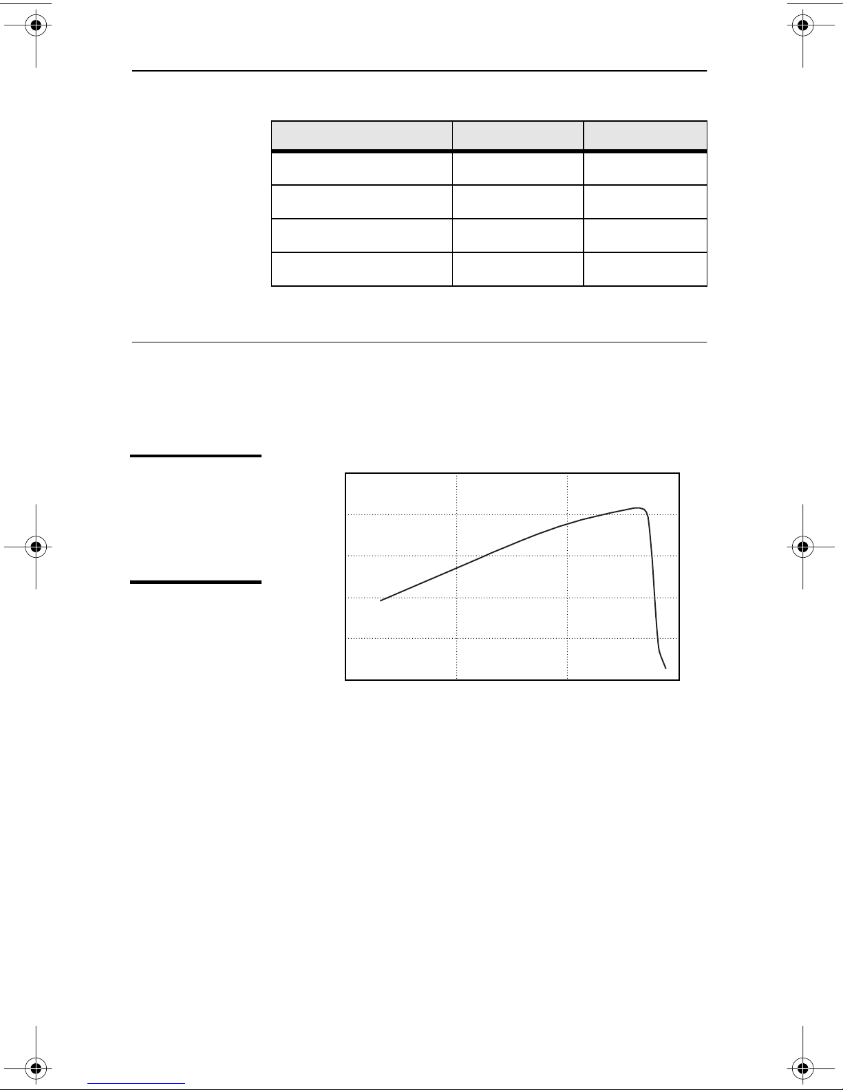
Figure 2:
Responsivity vs.
wavelength for
Models
1480 & 1481
Output Impedance 10 k
Ω
10 k
Ω
Bandwidth 50 kHz 50 kHz
A graph of the typical and predicted responsivity of
the Models 1480 and 1481 is shown below.
0.5
0.4
0.3
0.2
Responsivity, A/W
0.1
12 • Characteristics NEW FOCUS, Inc.
0
700600 800 900
Wavelength, nm
Page 13

Troubleshooting
Testing the Photodiode
The photodiode can be damaged by electrostatic
discharge or ex cessive optical po wer , which can lead to
an increased dark (or
photodiode can result in a degraded responsivity and
frequency/impulse response. See “Checking the DCOffset Voltage,” below.
offset
) voltage. A damaged
Checking the DC-Offset Voltage
1.
With no light on the photodetector, turn the
detector on.
2.
Use a voltmeter to measure the Bias Monitor
output voltage. This voltage is the DC offset plus
dark current.
3.
If the output is >10 mV, then the detector is
probably damaged and will need to be returned to
New Focus.
If the output is <10 mV, then perform the Basic
Basic Optical Test
To quickly test the photodiode in your receiver, run
this simple DC optical test.
1.
15-GHz & 25-GHz Photodetectors Troubleshooting • 13
Optical Test described below.
Turn the receiver on.
Page 14

2.
Using a voltmeter or oscilloscope, measure the
output voltage from the Bias Monitor on the front
panel of the bias supply.
With no light on the detector, the Bias Monitor
voltage should be <10 mV.
3.
Illuminate the photodetector.
4.
With the voltmeter or oscilloscope, you should
observe a DC output voltage.
If you know the optical power and wavelength,
you can calculate the expected output voltage
) using the expression:
(
V
out
Pin is the input optical power (watts), R is the
photodetector’s responsivity (A/W), and G is the
amplifier’s transimpedance gain (V/A). The gain of
the bias monitor port is 1000 V/A.
If the output voltage is low, then the fiber connector
may be dirty (see “Cleaning the Fiber Connector,”
below). If you suspect the unit is damaged, contact
New Focus to arrange for a repair (see “Customer
Service” on page 17).
Cleaning the Fiber Connector
The high-speed photodetectors have an internal fiber
connector and a fiber pigtail that brings the inp ut li ght
to the detector. If the fiber connector is dirty, this can
V
=
Pin • R • G, where
out
block the inpu t light so tha t li ght sent in t o the detecto r
will produce little or no output voltage.
Note also that if the fiber types are not compatib le (e.g .
multimode to single mode), this can also be the cause
of a very low output voltage.
To clean the fiber:
1.
2.
14 • Troubleshooting NEW FOCUS, Inc.
Turn off the module.
Blow filtered air or another inert gas (such as
nitrogen) into the input fiber connector. This will
Page 15
help to remove any dust or dirt particles that
might be blocking the input light.
If more cleaning is needed, proceed with steps 3-8.
3.
Wear a grounding strap.
4.
Remove the two screws on the back panel with a
Phillips screwdriver. Remove the back panel.
5.
Remove the two screws on the bottom of the
detector using an Allen key (1/16" o r 1.5-mm), and
carefully slide the detector housing off.
Caution: For steps 6–8, be extremely careful not to pull on the
fiber. The fiber is not designed to withstand excessive stress
where it connects to the microwave housing.
6.
Carefully disconnect the fiber connector from the
fiber receptacle attached to the front panel of the
detector.
7.
The front surface of the fiber can be cleaned using
acetone or alcohol and lens tissue.
8.
Carefully reconnect the fiber to the front panel
receptacle, re-install the detector housing (be
careful not to pinch or damage the fiber), and reinstall the back panel.
15-GHz & 25-GHz Photodetectors Troubleshooting • 15
Page 16

16 • Troubleshooting NEW FOCUS, Inc.
Page 17

Customer Service
Technical Support
Information and advice about the operation of any
New Focus product is available from our technical
support engineers.
Engineers are on duty from 8:00–5:00 PST, Monday
through Friday (excluding holidays). For quickest
response, ask for “Technical Support” and know the
model number f or your receiver. The model n umber is
printed on the front panel of the receiver.
Phone: (408) 980-8088
Fax: (408) 980-8883
Service
Support is also available by email.
Email: [email protected]
W e typically respond to email within one business day .
In the event that your photodetector malfunctions or
becomes damaged, please contact New Focus for a
return authorization number and instructions on
shipping the unit back for evaluation and repair.
15-GHz & 25-GHz Photodetectors Customer Service • 17
Page 18

18 • Customer Service NEW FOCUS, Inc.
Page 19

Appendix I: Microwave Connectors
The performance you obtain from the Model 148X
photodetector modules depends largely on the
instrument you use to measure their microwave
outputs and how the connections are made to this
instrument.
Connect the male connector of the photodetector
directly to the female connector of the instrument. If
an intervening coaxial cable is used, make sure it has
sufficiently low loss in the frequency range of interest
Even if you are not using an intervening cable,
performance can be degraded if an improper adapter is
chosen for mating to the instrument. Common SMA
connectors, for example, are intended for use only to
18 GHz. The followin g tab l e lists a few connectors and
the frequency ranges in which they may be used. (For
more information, request Application Note 1.)
Connector Frequency Range Compatibility
BNC DC–2 GHz ——
SMA DC–18 GHz Wiltron K, 3.5 mm
3.5 mm DC–34 GHz SMA, Wiltron K
Wiltron K DC–40 GHz SMA, 3.5 mm
2.4 mm DC–55 GHz Wiltron V
Wiltron V DC–65 GHz 2.4 mm
New Focus also offers the following adapters:
Model 1225 Male-SMA to Female-BNC
Model 1226 Female-SMA to Male-BNC
Model 1227 40-GHz Flex Cable, Female-K to Male-K
15-GHz & 25-GHz Photodetectors Appendix I: Microwave Connectors • 19
Page 20
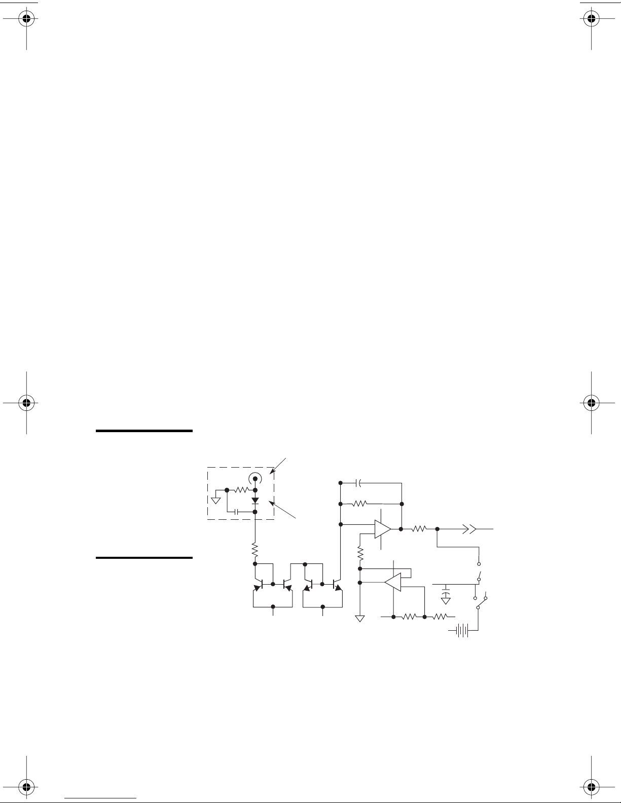
Appendix II:
Inside the Photodetector
A gold-plated microwave housing inside the
photodetector module contains the high-frequency
circuitry. This housing is bolted to a printed-circuit
board which regulates the bias for the photodiode and
amplifies the DC photocurrent for the monitor port.
The optical signal is brought from the front-panel
connector to the microwave housing with 9-cm fiber.
The fiber is protected by a sheet metal flange t o prev ent
damage while changing the battery. A simplified
schematic is provided below.
Figure 3:
Simplified
schematic of
the Models
1480 & 1481
photodetector
modules
Microwave
Housing
Microwave
Connector
Photodiode
+
V
Output
–
+
-
V
–
+
+
-
V
V
Batt
Chk
+
V
-
V
-
V
Bias
Monitor
On/Off
20 • Appendix II: Inside the Photodetector NEW FOCUS, Inc.
 Loading...