

Page 1

Artisan Technology Group is your source for quality
new and certied-used/pre-owned equipment
• FAST SHIPPING AND
DELIVERY
• TENS OF THOUSANDS OF
IN-STOCK ITEMS
• EQUIPMENT DEMOS
• HUNDREDS OF
MANUFACTURERS
SUPPORTED
• LEASING/MONTHLY
RENTALS
• ITAR CERTIFIED
SECURE ASSET SOLUTIONS
SERVICE CENTER REPAIRS
Experienced engineers and technicians on staff
at our full-service, in-house repair center
WE BUY USED EQUIPMENT
Sell your excess, underutilized, and idle used equipment
We also offer credit for buy-backs and trade-ins
www.artisantg.com/WeBuyEquipment
REMOTE INSPECTION
Remotely inspect equipment before purchasing with
our interactive website at www.instraview.com
LOOKING FOR MORE INFORMATION?
Visit us on the web at www.artisantg.com for more
information on price quotations, drivers, technical
specications, manuals, and documentation
Contact us: (888) 88-SOURCE | [email protected] | www.artisantg.com
SM
View
Instra
Page 2

Models 141X, 143X, 144X & 145X
USER’S MANUAL
FIBER-COUPLED, ULTRAHIGH-SPEED
PHOTODETECTOR MODULES
Artisan Technology Group - Quality Instrumentation ... Guaranteed | (888) 88-SOURCE | www.artisantg.com
Page 3

TABLE OF CONTENTS
141522 Rev.D
HANDLING PRECAUTIONS ..............................................................3
QUICK START ........................................................................................4
INTRODUCTION ..................................................................................5
OPERATION ..........................................................................................6
APPENDIX 1: USING AN OPTICAL FIBER ..................................10
APPENDIX 2: USING THE CORRECT
MICROWAVE CONNECTOR..................................11
APPENDIX 3: INSIDE THE PHOTODETECTOR MODULE ......12
TROUBLESHOOTING........................................................................13
DETECTOR CHARACTERISTICS ....................................................16
WARRANTY, SERVICE & SUPPORT ..............................................18
2
Is a registered trademark of
New Focus, Inc.
Artisan Technology Group - Quality Instrumentation ... Guaranteed | (888) 88-SOURCE | www.artisantg.com
Page 4

HANDLING PRECAUTIONS
The detector is sensitive to electrostatic discharges and could be
permanently damaged if subjected even to small discharges. Prior
to handling, or making connections, be sure to ground yourself
adequately. A ground strap provides the most effective grounding
and minimizes the likelihood of electrostatic discharge.
Do not over-torque the microwave K-connector. Excessive torque
can damage connectors.
Make sure the optical connector is clean and undamaged before
connecting to the detector module.
QUICK START
The Models 141X and 144X are high-speed InGaAs photodetector
modules for detection of light of wavelengths 950 to 1650 nm.The
143X and 145X are high-speed InGaAs photodetector modules for
detection of light of wavelengths 400 to 1650 nm. All the models
are 50-Ω terminated. An internal battery and bias circuitry make
the modules self-contained so that no additional power supplies
or bias circuitry are needed. To operate the modules, follow these
instructions:
1. Take proper precautions to avoid electrostatic damage to
the photodiode. (See the Handling Precautions above)
2. Remove module from its case.
3. Turn on power using the “Off/On”switch.
3
Artisan Technology Group - Quality Instrumentation ... Guaranteed | (888) 88-SOURCE | www.artisantg.com
Page 5

QUICK START
(Perform steps 4, 5 and 6 if using the detector for the first time or
you wish to check the battery and DC offset.)
4. Connect a voltmeter to the “Bias Monitor” SMA connector.
5. Press “Batt Chk” button.The voltage should be at least 3.5 V.
6. Release the “Batt Chk” button.Without an optical input, the
voltage should be less than 10 mV.
7. Connect the photodetector module to your measurement
instrument, being careful not to over-torque the K-connector.
The instrument must have a 50-Ωinput impedance.
8. Check that the optical power emerging from your fiber is
below the Max. Pulse Power or cw Saturation Power as
appropriate (see the Detector Characteristics section of this
manual) to ensure detector linearity and to avoid detector
damage.
9. Connect your optical fiber to the connector on the detector
module.
10.When finished using the module, turn off power to preserve
battery life.
If any of these steps present problems or you would like more
information, please consult the remainder of this manual.
4
Artisan Technology Group - Quality Instrumentation ... Guaranteed | (888) 88-SOURCE | www.artisantg.com
Page 6

INTRODUCTION
Ultrahigh-speed measurements are easy with the Models 141X,
143X, 144X and 145X high-speed photodetector modules.These
modules convert your optical signals to electronic signals, in effect,
giving every high-speed/high-frequency instrument in your lab
an optical input. The modules are connected directly to the test
instrument or amplifier, eliminating the need for coaxial cables following the photodetector which can seriously distort picosecond
pulses and attenuate microwave signals.The optical signal is
delivered to the Schottky photodiode in the module through a
single-mode or multi-mode optical fiber. Moreover, the photodiode bias circuit and battery are self-contained, eliminating the
hassle of external power supplies and expensive bias networks
and reducing the possibility of photodiode damage due to overvoltage.
New Focus offers a total of eight models, allowing you to match
your wavelength of interest and the connector style of your instrumentation.The Models 141X and 144X are high-speed InGaAs
photodetector modules for detection of light of wavelengths 950
to 1650 nm, and the Models 143X and 145X are also high-speed
InGaAs photodetectors designed for 400-1650 nm operation .
Models 141X and 143X are optimized for a flat frequency response,
and the Models 144X and 145X are optimized to achieve an
impulse response with minimal ringing. All models are 50-Ω termi-
nated to reduce reflections in 50-Ω systems and to make them
compatible with 50-Ω receiver filters. All detectors have single-
mode FC or ST fiber connectors, and an option (-50) is available for
a 50 µm core multimode fiber input. Each models‘ characteristics
are listed and their responsivity-vs.-wavelength curves are shown
in the Detector Characteristics section of this manual.
5
Artisan Technology Group - Quality Instrumentation ... Guaranteed | (888) 88-SOURCE | www.artisantg.com
Page 7

OPERATION
Checking the battery and offset voltage:
The battery and offset voltage should be checked regularly to
ensure proper functioning of the detector.
1. Turn on the module using the power switch.
2. Connect the “Bias Monitor”port to a voltmeter.
3. Press and hold the “Batt Chk” button and observe the bias
monitor output.The photodiode bias voltage is momentarily
applied to the “Bias Monitor”SMA connector. A reading of 5 V
on this connector is typical with a new battery; the battery
should be replaced when the voltage reaches 3.5 V.
4. Release the “Batt Chk” button and observe the voltage level on
the voltmeter. Without an optical input, this voltage is the DC
offset plus dark current. This “dark voltage”should be less than
10 mV.
5. If needed, keep the voltmeter connected to the module to
optimize coupling to the fiber.
Making the Microwave Connection
Connect the microwave output connector of the photodetector
module to a 50-Ω input test instrument such as an oscilloscope
or spectrum analyzer, or other 50-Ω load using the proper torque.
To avoid connector damage and signal distortion, be sure that the
instrument you intend to connect to the module has a compatible
connector. See Appendix 2: Using the Correct Microwave Connector
for a list of connector compatibilities.
Aligning the Photodetector to the Optical Input:
To avoid signal distortion, the optical fiber used to deliver the
optical signal to the photodetector module should be single
mode at the operating wavelength and the cable length should
be no longer than necessary.
6
Artisan Technology Group - Quality Instrumentation ... Guaranteed | (888) 88-SOURCE | www.artisantg.com
Page 8

OPERATION
1. If you do not currently have an ST- or FC-terminated optical
fiber, use either a pigtail assembly or a fiber collimator (see
Table 1), and align the fiber so that light exits the output fiber
connector.With a pigtail assembly, use a fiber aligner such as
the Model 9091 and its accessories; with a collimator, use the
Model 9854 Opti-Claw or the Model 9016 tiny fiber positioner.
2. Measure the power in the fiber prior to connection to the
module to be sure it is within the safe operating range (see
the Detector Characteristics section of this manual). The Models
20X1-FC and 20X1-ST are useful for this purpose and have the
sensitivity to aid in fiber alignment.
3. Connect the fiber-optic cable to the fiber-optic input on the
detector module.The Bias Monitor may be used to optimize
coupling to the fiber.
7
Artisan Technology Group - Quality Instrumentation ... Guaranteed | (888) 88-SOURCE | www.artisantg.com
Page 9

OPERATION
Table 1. Fiber-optic cable assembly selection table.
Optical Input Fiber Assembly Required
830 nm wavelength Model 1233 collimator-FC (2 meters) for 1434,1454
1.3 µm wavelength Model 1237 collimator-FC (2 meters) for 1414,1444
1.55 µm wavelength Model 1238 collimator-FC (2 meters) for 1414,1444
600 to 900 nm wavelength Model 1223 pigtail-FC assembly (2 meters) for 1434,1454
1.1 to 1.6 µm wavelength Model 1232 pigtail-FC assembly (2 meters) for 1414,1444
1.1 to 1.6 µm wavelength Model 1222 ST-FC (2 meters)
These assemblies are available from New Focus.
Collimators require an Opti-Claw tilt-mount such as the Model 9854.
Pigtail assemblies require a fiber aligner such as the Model 9091.
Other wavelengths and beam types
Patch Cable
< 2 mm diameter collimated beam at:
8
Artisan Technology Group - Quality Instrumentation ... Guaranteed | (888) 88-SOURCE | www.artisantg.com
Page 10

APPENDICES
Replacing the battery:
1. Turn off the module and remove the two screws on the back
panel with a Phillips screwdriver. (See Fig. 1.)
2. Remove the back panel and replace the battery.
3. Replace the back panel.
4. Check the battery level as described above.
Fig. 1. Front, side,and rear views of the Models 141X, 143X,144X and
145X fiber-coupled photodetector modules.
Power Switch
Battery Check Button.
When depressed, bias
voltage is applied to bias
monitor port
2.00 (50.8)
Remove two screws
to replace 9V battery
2.00
(50.8)
3.27 (82.9)
2.25 (57.1)
Bias monitor port.
Output is equal to photodiode current
times 1000 ohms, for one millivolt
per microamp
Output K-connector
Shown with ST connector
for optic input
1411 ST connector
1414 FC connector
1431 ST connector
1434 FC connector
1441 ST connector
1444 FC connector
1451 ST connector
1454 FC connector
9
Artisan Technology Group - Quality Instrumentation ... Guaranteed | (888) 88-SOURCE | www.artisantg.com
Page 11

APPENDICES
APPENDIX 1: USING AN OPTICAL FIBER
Single mode optical fiber can provide low loss and low distortion if
attention is paid to a few important details. First, if more than one
mode is allowed to propagate in a step-index fiber, the bandwidth
will be degraded to approximately ƒ
3-dB
= [cn] / [2L(NA)2], where c is
the speed of light in free space, n is the index of the core, L is the
length of the fiber, and NA is the numerical aperture of the fiber.
Modal distortion can be eliminated by using a fiber with a core
small enough that only a single mode will propagate. In this case,
the bandwidth of the fiber will be limited by material dispersion
which is a property of the glass used in the fiber core. In this limit,
the bandwidth is approximately* ƒ
3-dB
= 1 / [2LM∆λ], where L is the
fiber length in kilometers, M is the material dispersion in ps/(nm ×
km), and ∆λ is the line width of the optical source in nm. This
bandwidth limitation can be ignored for glass fibers less than 10
meters in length, but can be serious for longer fibers and spectrally
broad sources.
10
*Palais, C.J., Fiber Optic Communications, Prentice-Hall, Inc., Englewood Cliffs, NY., 1984
Artisan Technology Group - Quality Instrumentation ... Guaranteed | (888) 88-SOURCE | www.artisantg.com
Page 12

APPENDICES
APPENDIX 2: USING THE CORRECT MICROWAVE CONNECTOR
The performance you obtain from the Model 14XX photodetector
modules will depend largely on the instrument you use to measure its microwave output and how the connection is made to
this instrument.The male connector of the photodetector module
should be connected directly to the female connector of the
instrument. If an intervening coaxial cable is used, care must
be exercised in selecting a cable that has sufficiently low loss in
the frequency range of interest. Even if a coaxial cable is not used,
performance can be degraded if an improper adapter is chosen for
mating to the instrument. Common SMA connectors, for example,
are intended for use to only 18 GHz.Table 2 is a list of a few connectors and the frequency range in which they may be used.
Table 2. Common RF connectors and the corresponding frequency
ranges in which they are useful.
11
Connector Type Frequency Range Compatibility
BNC DC-2 GHz —
SMA DC-18 GHz Wiltron K, 3.5 mm
Wiltron K DC-40 GHz SMA, 3.5 mm
2.4 mm DC-55 GHz Wiltron V
Wiltron V DC-65 GHz 2.4 mm
3.5 mm DC-34 GHz SMA, Wiltron K
New Focus also offers the following products:
Model 1224 Female-V to Male-K
Model 1225 Male-SMA to Female-BNC
Model 1226 Female-SMA to Male-BNC
Model 1227 40-GHz Flex Cable, Female-K to Male-K
Artisan Technology Group - Quality Instrumentation ... Guaranteed | (888) 88-SOURCE | www.artisantg.com
Page 13
APPENDICES
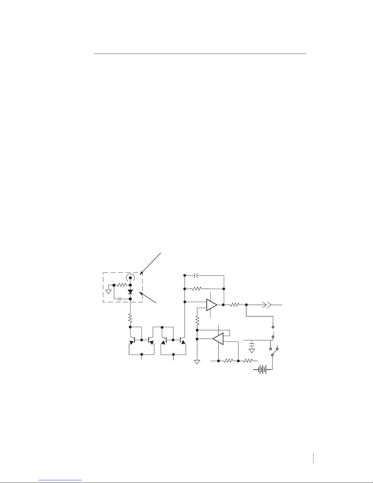
APPENDIX 3: INSIDE THE PHOTODETECTOR MODULE
Inside the photodetector module is a gold-plated microwave
housing that contains the high-frequency circuitry.This housing is
bolted to a printed-circuit board which regulates the bias for the
photodiode and amplifies the DC photocurrent for the monitor
port. The optical signal is brought from the front-panel connector
to the microwave housing with a 0.2-meter, 9-µm core fiber.
Although the material and modal dispersion per unit length of this
fiber can be high at certain wavelengths, there is no degradation
in frequency response since the fiber is only 0.2 meters long.
The fiber is protected by a sheet metal flange to prevent damage
while changing the battery. A simplified schematic is provided in
Fig.2 for your reference.
Fig. 2. Simplified schematic diagram of the 141X,143X, 144X,and 145X
series photodetector modules.
–
+
–
+
Microwave
Housing
Photodiode
Microwave
Output
Connector
V
+
V
-
V
+
V
-
V
-
On/Off
Batt
Chk
Bias
Monitor
V
+
V
-
12
Artisan Technology Group - Quality Instrumentation ... Guaranteed | (888) 88-SOURCE | www.artisantg.com
Page 14

TROUBLESHOOTING
Several problems which can arise with the detector modules and
procedures to check for them are outlined below.
Problems:
Damaged photodiode/Excessive offset voltage: The photodi-
ode can be damaged by electrostatic discharge or excessive
optical power, and both causes lead to an increased dark (or offset)
voltage. A damaged photodiode can result in a degraded responsivity and frequency/impulse response. See DC Offset Voltage
below.
Low bias voltage: If the photodiode bias voltage is too low, the
frequency/impulse response of the detector will degrade, as will
the responsivity. See Checking the Battery below.
Dirty fiber-optic connector: A dirty fiber-optic connector can
cause an apparent degradation of responsivity. See Basic Optical
Test below.
Tests Procedures and Solutions:
DC Offset Voltage
With no light on the photodetector, turn the detector on and use a
voltmeter to measure the Bias Monitor output voltage.This voltage
is the DC offset plus dark current. If the output is >10 mV, then the
detector is probably damaged and will need to be returned to
New Focus.
Checking the Battery
1. Turn on the module using the power switch.
2. Connect the “Bias Monitor”port to a voltmeter.
3. Press and hold the “Batt Chk” button and observe the bias mon-
itor output.The photodiode bias voltage is momentarily applied
to the “Bias Monitor”SMA connector. A reading of 5 V on this
connector is typical with a new battery; the battery should be
replaced when the voltage reaches 3.5 V.
13
Artisan Technology Group - Quality Instrumentation ... Guaranteed | (888) 88-SOURCE | www.artisantg.com
Page 15

TROUBLESHOOTING
Replacing the Battery
1. Turn off the module and remove the two screws on the back
panel with a Phillips screwdriver. (See Fig. 1.)
2. Remove the back panel and replace the battery.
3. Replace the back panel.
4. Check the battery level as described above.
Basic Optical Test
To quickly test whether a photodetector appears to be working,
you can perform a simple DC optical test:
1. Turn the detector on.
2. Using a voltmeter or oscilloscope, measure the output voltage
from the Bias Monitor on the front panel. (With no light on the
detector, the Bias Monitor voltage should be <10 mV.)
3. Couple some CW light into the photodetector.
4. With the voltmeter or oscilloscope, you should observe a DC
output voltage. If you know the optical power and wavelength,
you can calculate the expected output voltage (V
out
) using the
expression: V
out
= Pin• R • G, where Pinis the input optical power
(watts), R is the photodetector’s responsivity (A/W ), and G is the
amplifier’s transimpedance gain (V/A). The gain of the bias
monitor port is 1000 V/A.
If the output voltage appears to be low, then the fiber connector
might be dirty. If a dirty connector is suspected, see Cleaning the
Fiber Connector below.
Cleaning the Fiber Connector
The high-speed photodetectors have an internal fiber connector
and a fiber pigtail that brings the input light to the detector.If the
fiber connector is dirty, this can block the input light so that light
14
Artisan Technology Group - Quality Instrumentation ... Guaranteed | (888) 88-SOURCE | www.artisantg.com
Page 16

TROUBLESHOOTING
sent into the detector will produce little or no output voltage.
Note also that if the fiber types are not compatible (single-mode
with multi-mode, and vice-versa), this can also be the cause of a
very low output voltage.
To clean the fiber:
1. Turn off the module.
2. Blow filtered air or another inert gas (such as nitrogen) into the
input fiber connector.This will help to remove any dust or dirt
particles that might be blocking the input light.
If more cleaning is needed, proceed with steps 3-8.
3. Wear a grounding strap.
4. Remove the two screws on the back panel with a Phillips
screwdriver.Remove the back panel.
5. Remove the two screws on the bottom of the detector using
an Allen key (1/16” or 1.5-mm), and carefully slide the detector
housing off.
Steps 6-8: Be extremely careful not to pull on the fiber. Stress
applied to the fiber where it attaches to the microwave housing can cause the fiber to misalign from the photodiode,
resulting in degraded detector performance.
6. Carefully disconnect the fiber connector from the fiber
receptacle attached to the front panel of the detector.
7. The front surface of the fiber can be cleaned using acetone
or alcohol and lens tissue.
8. Carefully reconnect the fiber to the front panel receptacle,
re-install the detector housing (be careful not to pinch or
damage the fiber), and re-install the back panel.
15
Artisan Technology Group - Quality Instrumentation ... Guaranteed | (888) 88-SOURCE | www.artisantg.com
Page 17

DETECTOR CHARACTERISTICS
16
Model # 1411(1414) 1431(1434) 1441(1444) 1451(1454)
Wavelength Range
(multimode versions)
950-1650 nm
950-1650 nm
400-1650 nm
550-1330 nm
950-1650 nm
950-1650 nm
400-1650 nm
550-1330 nm
Max. Full Width at
Half Maximum
• •
18.5 ps 18.5 ps
Min. 3-dB Bandwidth
(Electrical)
25 GHz 25 GHz
• •
Conversion Gain
at Peak
λλ
15 V/W 5 V/W 15 V/W 5 V/W
Responsivity
at Peak
λλ
0.6 A/W 0.2 A/W 0.6 A/W 0.2 A/W
Output Impedance
50 Ω 50 Ω 50 Ω 50 Ω
Min. NEP 30 pW/√Hz 90 pW/√Hz 30 pW/√Hz 90 pW/√Hz
cw Saturation
Power
2 mW 10 mW 2 mW 10 mW
Max. Pulse Power 100 mW 200 mW 100 mW 200 mW
Detector Material InGaAs InGaAs InGaAs InGaAs
Detector Type Schottky Schottky Schottky Schottky
Detector Diameter 25 µm 25 µm 25 µm 25 µm
Power
Requirements
9-V battery 9-V battery 9-V battery 9-V battery
Optical Input* ST(FC) ST(FC) ST(FC) ST(FC)
Bias Monitor:
DC Gain
1 mV/µA 1 mV/µA 1 mV/µA 1 mV/µA
DC Offset <10 mV <10 mV <10 mV <10 mV
Output Impedance
1 kΩ 1 kΩ 1 kΩ 1 kΩ
Bandwidth 50 kHz 50 kHz 50 kHz 50 kHz
Electrical Output Wiltron K Wiltron K Wiltron K Wiltron K
*Single mode. Specify the -50 option for a 50 micron core multimode fiber.
Artisan Technology Group - Quality Instrumentation ... Guaranteed | (888) 88-SOURCE | www.artisantg.com
Page 18
DETECTOR CHARACTERISTICS
17
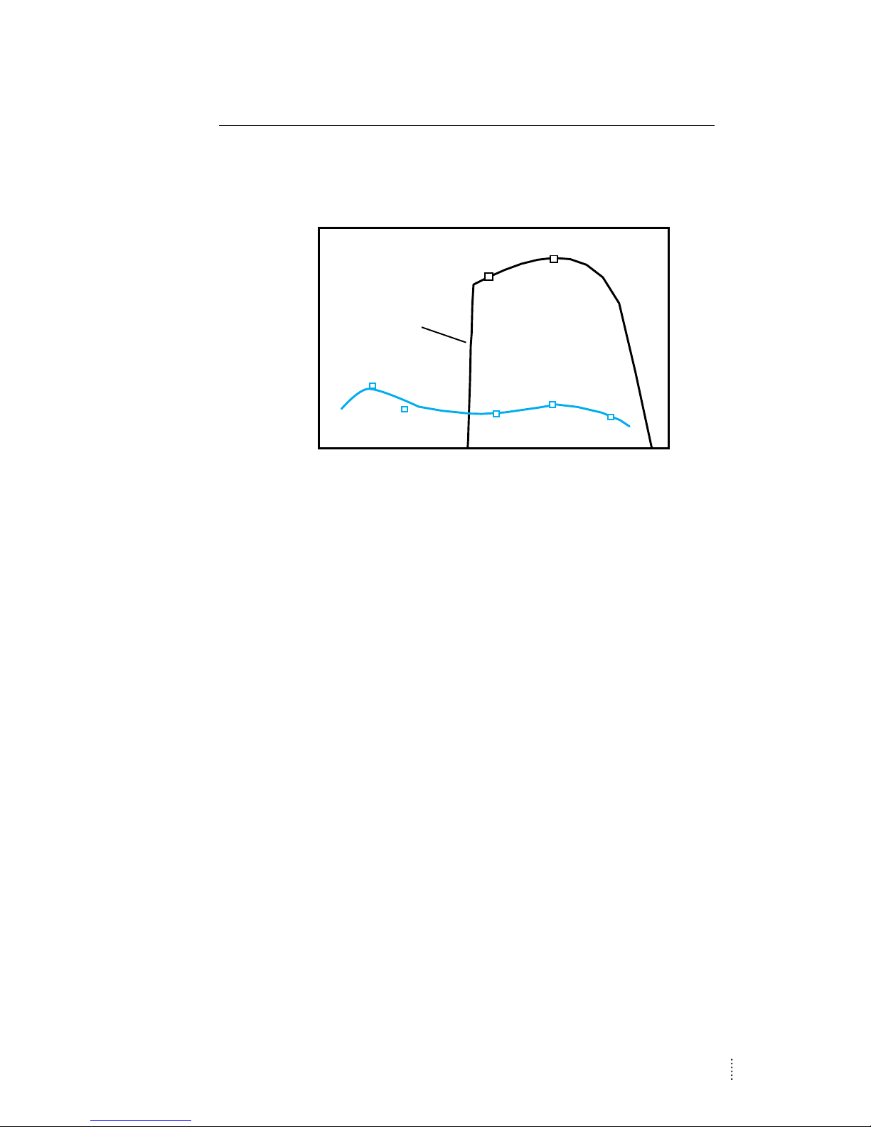
Fig 3. Responsivity vs. wavelength for a) Models 143X and145X and b)
Models 141X and 144X.
Responsivity
increases
from 0–0.52 A/W
over the range of
950–970 nm.
Wavelength, nm
Responsivity, A/W
300
500 700
900
1100
1300
1500 1700
0.0
0.2
0.4
0.6
a
b
Artisan Technology Group - Quality Instrumentation ... Guaranteed | (888) 88-SOURCE | www.artisantg.com
Page 19

WARRANTY, SERVICE & SUPPORT
New Focus,Inc. guarantees its products to be free of defects for
one year from the date of shipment.This is in lieu of all other
guarantees, expressed or implied, and does not cover incidental
or consequential loss.
TECHNICAL SUPPORT
Information and advice about the operation of your New Focus
products is available from our technical support engineers.
Engineers are on duty from 8:00–5:00 PST, Monday through Friday
(excluding holidays). For quickest response, ask for “Technical
Support”and know the model number for your product.
Phone: (408) 980-8088
Fax: (408) 980-8883
Support is also available by email.
Email: [email protected]
We typically respond to email within one business day.
SERVICE
In the event that your translation stage malfunctions or becomes
damaged, please contact New Focus for a return authorization
number and instructions on shipping the unit back for evaluation
and repair.
18
Artisan Technology Group - Quality Instrumentation ... Guaranteed | (888) 88-SOURCE | www.artisantg.com
Page 20

Artisan Technology Group is your source for quality
new and certied-used/pre-owned equipment
• FAST SHIPPING AND
DELIVERY
• TENS OF THOUSANDS OF
IN-STOCK ITEMS
• EQUIPMENT DEMOS
• HUNDREDS OF
MANUFACTURERS
SUPPORTED
• LEASING/MONTHLY
RENTALS
• ITAR CERTIFIED
SECURE ASSET SOLUTIONS
SERVICE CENTER REPAIRS
Experienced engineers and technicians on staff
at our full-service, in-house repair center
WE BUY USED EQUIPMENT
Sell your excess, underutilized, and idle used equipment
We also offer credit for buy-backs and trade-ins
www.artisantg.com/WeBuyEquipment
REMOTE INSPECTION
Remotely inspect equipment before purchasing with
our interactive website at www.instraview.com
LOOKING FOR MORE INFORMATION?
Visit us on the web at www.artisantg.com for more
information on price quotations, drivers, technical
specications, manuals, and documentation
Contact us: (888) 88-SOURCE | [email protected] | www.artisantg.com
SM
View
Instra
 Loading...