

Page 1

Models 1421 and 1422
User’s Manual
Broadband Amplifiers
Page 2

2
Is a registered trademark of
New Focus, Inc.
142101 Rev. A
Page 3

Contents
Warranty
Introduction
Operation
Specifications
3
4
5
8
Warranty
New Focus, Inc. guarantees its products to
be free of defects for one year from the date of
shipment. This is in lieu of all other guarantees,
expressed or implied, and does not cover incidental or consequential loss.
3
Page 4

4
Introduction
The Model 1421 and 1422 Broadband Amplifiers
are designed specifically for use as low-noise
amplifiers following a high-speed photodetector
such as the Model Series 14XX and 10XX. These
amplifiers are specified over a 50-MHz-to-20-GHz
bandwidth and have good small-signal step
response as well. This makes them suitable for
both time- and frequency-domain applications.
Page 5

5
Operation
The Model 1421 and 1422 Broadband Amplifiers
are housed in a compact unit whose input and
output connectors are Wiltron K-connectors. A
female connector is used on the input to mate with
the male connector used on the output of New
Focus’ High-speed Photodetectors. (See Fig.1.) In
addition, there is a captive screw piercing the unit
that allows the amplifier to be fastened to any
Model 10XX or 14XX Series photodetector module.
The connection is made by removing the left-most
screw on the battery cover of a Series 10XX detector
or using the hole provided on a Series 14XX detector. The RF connectors should then be mated but
not fully torqued. Next, use a 1/8" Allen wrench or
ball-driver to fasten the captive screw to the photodetector. Finally, tighten the RF connectors to
their proper torque. To allow proper alignment of
the RF connectors, the microwave amplifier housing floats freely inside the black anodized
casing.The captive screw along with the RF connectors, provides a rigid assembly that can be used
as a unit. The screw is also useful in cascading
many Model 1421 or 1422 amplifiers.
Page 6

6
When a Model 1421 or 1422 amplifier is not being
cascaded with other amplifiers, the male output
connector may be inconvenient. For this situation,
New Focus offers a cable assembly with a female Kconnector on one end and a male K-connector on
the other: Model 1227 40-GHz Cable Assembly.
DC-power is supplied to the amplifier via a 3-pin
Microtech connector. This is the same connector
used on the New Focus Model 0901 Power Supply.
Two cables are provided for the power connection.
If the Model 1421 or 1422 is to be used with the
Model 0901, use the Microtech-to-Microtech connector cable only. If the Model 1421 or 1422 is to
be used with a power supply other than the Model
0901, use the Microtech-to-banana cable and
observe the following precautions:
• Input voltage range is 15 to 8 V at 250 mA on the
positive (red) banana plug.
• Input voltage range is -15 to -8 V at 100 mA on
the negative (black) banana plug.
• The negative supply must be turned on first or
simultaneously with the positive supply. If the
positive supply is turned on first, the unit could
be destroyed.
• The two supplies should share a common
ground which should be connected to the green
banana plug.
Page 7
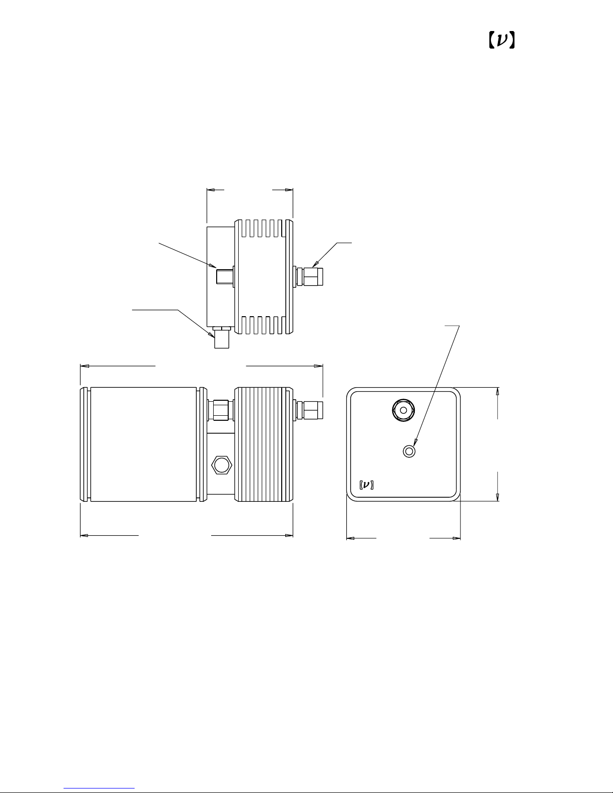
Fig. 1
Front, side, and rear views of the Model 1421
and 1422 amplifier modules.
4.26 (109.2)
Power Connector
±15 V
Fastener for use
with Model 10XX or
14XX detectors
K-connector
Male Output
Connector
K-connector
Female Input
Connector
1.51
(38.14)
3.74 (94.8)
2.00
(50.8)
2.00
(50.8)
Model 10XX or
14XX Detectors
(Not Included)
.05-20 GHz Amplifier
1421
7
Page 8

8
Model 1421
Specifications
Nominal Gain: 8.5 dB
Gain Flatness:
1
±1.5 dB
Max. Power Out:
2
10 dBm
Max. AC Input:
2
10 dBm
Max. DC Input: 10 V
VSWR:
3
1.8:1 input
2.1:1 output
Noise Figure:
4
8 dB
Input Noise: 22 pA/√Hz
Impulse Response: 20 ps
Frequency Response:
5
50 MHz–20 GHz
Input Impedance: 50 Ω
Output Impedance: 50 Ω
Power Requirements: ±15 V, <150 mA
(To protect the amplifiers from possible incorrect connections we
recommend the Model 0901.)
1
This is the variation of the gain over the entire frequency bandwidth.
For instance, the 1421 has a gain that varies from 7 dB to 10 dB. In
terms of voltage gain, this is the variation from 2.2 to 3.2.
2
In a 50-Ω system, 10 dBm=1.0 V peak.
3
The VSWR is the Voltage Standing-Wave Ratio. It is the ratio between
a maximum and a minimum of a standing wave that occurs because of
the impedance mismatch. A VSWR value of 1 indicates a perfectly
matched system. For a reflection coefficient R,
4
Noise Figure is the amount of excess input noise above -174 dBm in a
1 Hz bandwidth and at 290 K. In a 50-Ω system, 8 dB corresponds to an
input noise current of 22 pA/Hz.
5
We offer an option which extends the low frequency cutoff to 14 MHz.
VSWR
1
R
1
R
=
+
−
Page 9

9
Model 1422
Specifications
Nominal Gain: 18 dB
Gain Flatness:
1
±2 dB
Max. Power Out:
2
10 dBm
Max. AC Input:
2
10 dBm
Max. DC Input: 10 V
VSWR:
3
1.8:1 input
2.1:1 output
Noise Figure:
4
8 dB
Input Noise: 22 pA/√Hz
Impulse Response: 25 ps
Frequency Response:
5
50 MHz–20 GHz
Input Impedance: 50 Ω
Output Impedance: 50 Ω
Power Requirements: ±15 V, <300 mA
(To protect the amplifiers from possible incorrect connections we
recommend the Model 0901.)
1
This is the variation of the gain over the entire frequency bandwidth.
For instance, the 1421 has a gain that varies from 7 dB to 10 dB. In
terms of voltage gain, this is the variation from 2.2 to 3.2.
2
In a 50-Ω system, 10 dBm=1.0 V peak.
3
The VSWR is the Voltage Standing-Wave Ratio. It is the ratio between
a maximum and a minimum of a standing wave that occurs because of
the impedance mismatch. A VSWR value of 1 indicates a perfectly
matched system. For a reflection coefficient R,
4
Noise Figure is the amount of excess input noise above -174 dBm in a
1 Hz bandwidth and at 290 K. In a 50-Ω system, 8 dB corresponds to an
input noise current of 22 pA/Hz.
5
We offer an option which extends the low frequency cutoff to 14 MHz.
VSWR
1
R
1
R
=
+
−
Page 10
10
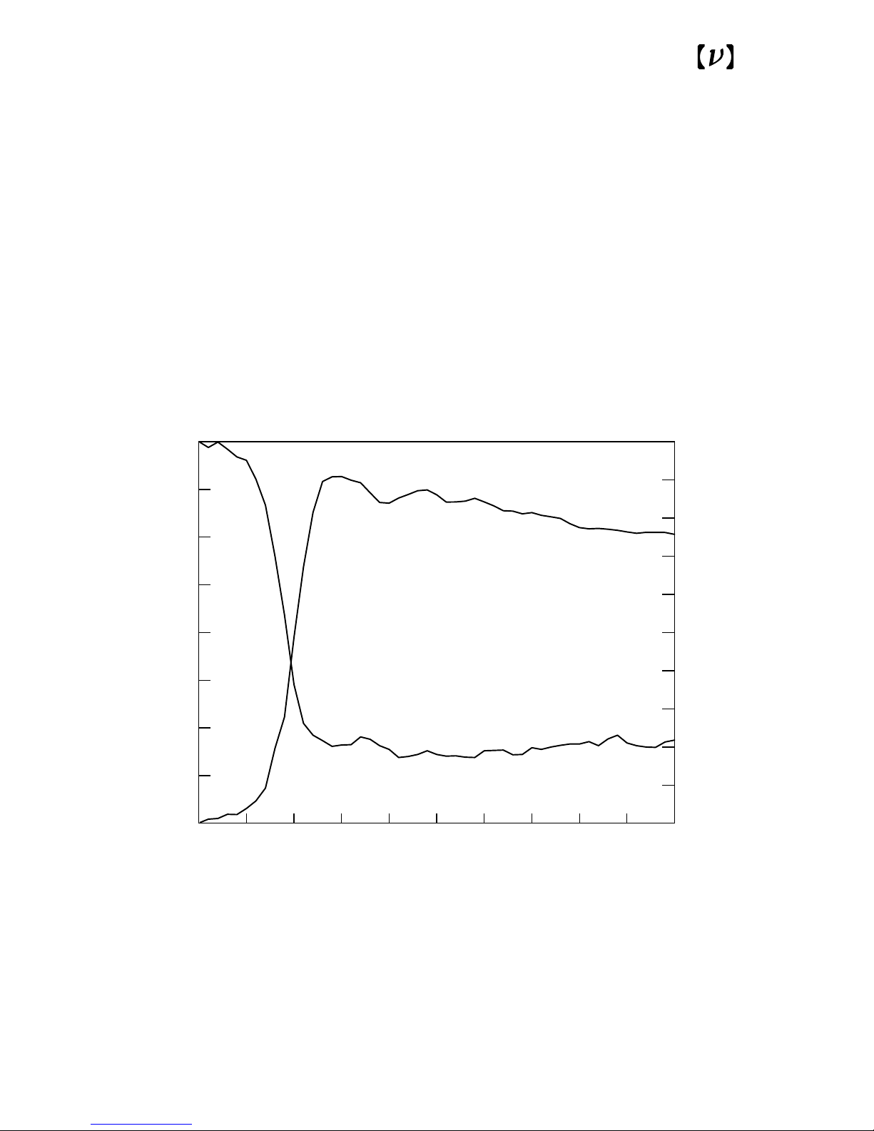
Fig. 2
Typical response of the Models 1421 and
1422 amplifiers to a 120-mV, 50-ps,
positive step-function input.
0 500
-0.40
0.00
50 ps/div
0.0
1.0
Model 1421
Model 1422
Model 1421 Output
(Volts)
Model 1422 Output
(Volts)
Page 11
11
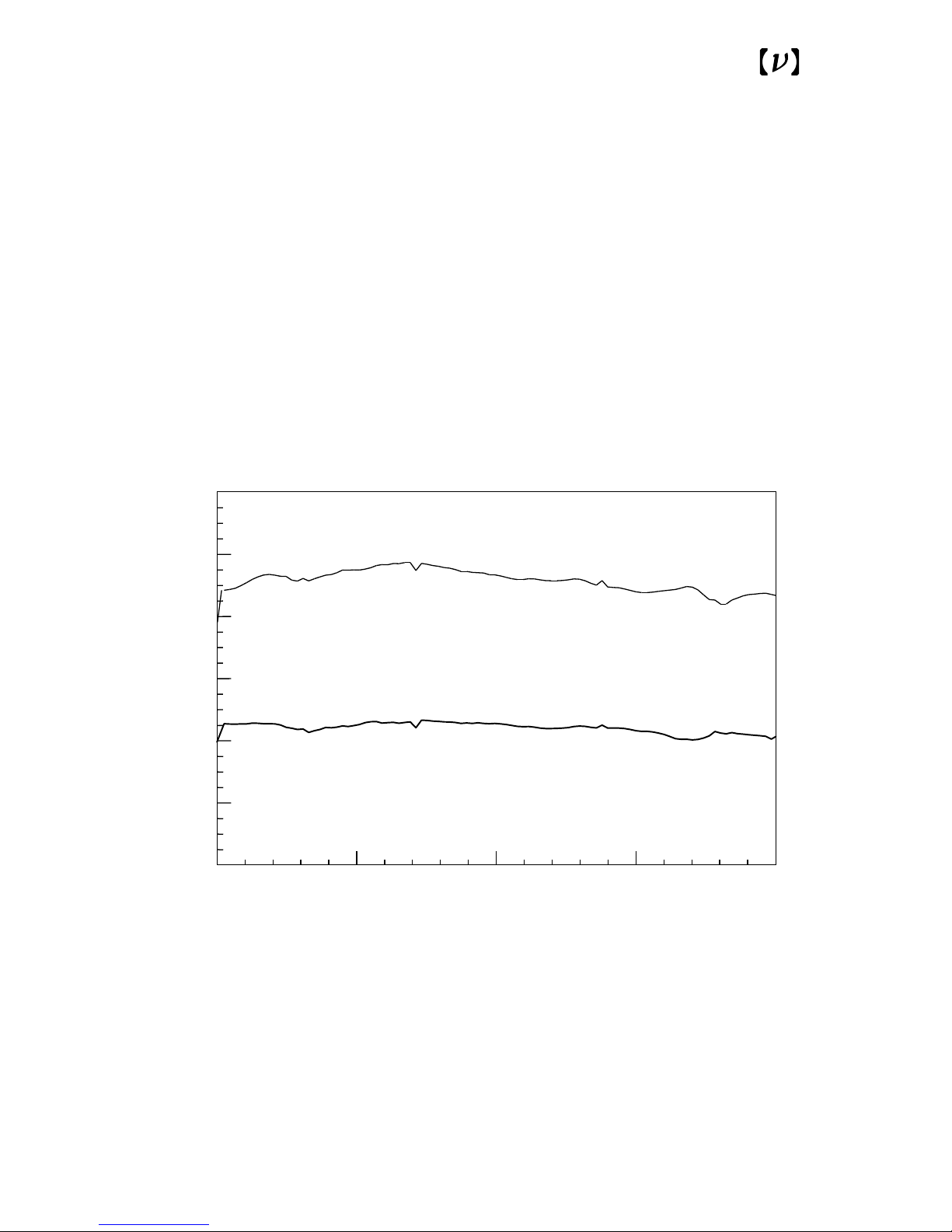
Fig. 3
Typical frequency response of the
Models 1421 and 1422 Amplifiers.
0 5 10 15 20
0
4
8
12
16
20
24
Frequency (GHz)
Gain (dB)
Model 1421
Model 1422
Page 12

12
Notes
 Loading...