

New Buck Corporation FS 21 User Manual
MODEL FS 21
NON-CATALYTIC UNIT
B
u
c
k
S
t
o
v
e
FEATURES
PREPARATIONS INSTALLATION
OPERATION MAINTENANCE SAFETY
SAFETY NOTICE
IF THIS HEATER IS NOT PROPERLY INSTALLED, A HOUSE FIRE MAY
RESULT. FOR YOUR SAFETY, FOLLOW THE INSTALLATION
INSTRUCTIONS. CONTACT THE AUTHORITY HAVING JURISDICTION
(SUCH AS MUNICIPAL BUILDING DEPARTMENT, FIRE DEPARTMENT, FIRE
PREVENTION BUREAU, etc.) CONSULT BEFORE INSTALLATION TO
DETERMINE THE NEED TO OBTAIN A PERMIT. KEEP THESE
INSTRUCTIONS FOR FUTURE USE.
TESTED AND LISTED BY: ITS/WARNOCK HERSEY, MIDDLETON, WI
MANUFACTURED BY NEW BUCK CORPORATION
200 ETHAN ALLEN DRIVE
P.O. BOX 69
SPRUCE PINE, N.C. 28777
www.buckstove.com
Revised July 2010


TABLE OF CONTENTS
Important Instructions ......................................................................................................................... 2
SECTION I: Introduction ................................................................................................................... 3
SECTION II: Residential /Mobile Home Freestanding Installation and Clearances ......................... 4
Floor Protection .................................................................................................................................. 5
A. Vertical Exit Using Single Wall Pipe /Listed 2100° UL 103 HT chimney w/out
Close Clearance/Pipe Shields ....................................................................................................... 6
B. Vertical Wall Exit Using Single Wall Pipe and Elbow /Listed 2100° UL 103 HT Chimney
and T-BOX assembily w/out Close Clearance/Pipe Shields ........................................................ 8
C. Vertical Exit Using DVL Close Clearance Pipe /Listed 2100° UL 103 HT chimney with
Close Clearance/Pipe Shields ..................................................................................................... 10
D. Vertical Wall Exit Using DVL Close Clearance Pipe ,and Elbow /Listed 2100° UL 103 HT
Chimney and T-BOX assembly with Close Clearance/Pipe Shields .......................................... 12
Out Side Air Installation ................................................................................................................... 14
SECTION III: Alcove Installation and Clearances .......................................................................... 17
Floor Protection .......................................................................................................................... 18
Alcove Installation Clearances .............................................................................................. 19-20
Installation of Close Clearances Shields ........................................................................................... 22
SECTION IV: Operation .................................................................................................................. 23
Ash Removal .................................................................................................................................... 24
SECTION V: Optional Motor Installation ....................................................................................... 25
SECTION VI: Wood Heater Safety ................................................................................................. 28
SECTION VII: Troubleshooting ...................................................................................................... 29
LIMITED WARRANTY .................................................................................................................. 30

INSTALLATION, OPERATION, AND
MAINTENANCE INSTRUCTIONS
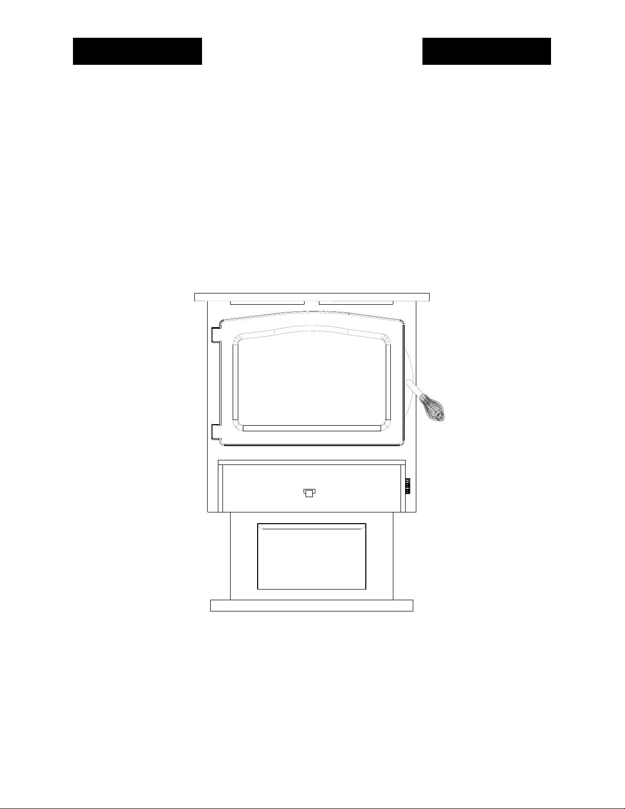
MODEL FS 21
READ THIS FIRST
IMPORTANT INSTRUCTIONS
WARNING
THIS UNIT GENERATES A LOT OF HEAT, SO TREAT THE UNIT WITH CARE.
HOT WHILE IN OPERATION! KEEP CHILDREN, CLOTHING AND FURNITURE
AWAY. CONTACT MAY CAUSE SKIN BURNS.” “DO NOT USE CHEMICALS OR
FLUIDS TO START THE FIRE.” “DO NOT BURN GARBAGE OR FLAMMABLE
FLUIDS.” DO NOT CONNECT TO ANY DISTRIBUTION DUCT OR SYSTEM. READ
ALL INSTRUCTIONS BEFORE INSTALLING AND USING THE APPLIANCE.
FAILURE TO FOLLOW INSTRUCTIONS MAY RESULT IN PROPERTY DAMAGE,
BODILY INJURY OR EVEN DEATH. SAVE THESE INSTRUCTIONS FOR FUTURE
REFERENCES.
The New Buck Corp. non-catalytic systems have been tested by ITS, Warnock Hersey to
ANSI/UL Standards: UL 1482-2000: UL 1482 (2010).
Install and operate your units according to instructions provided in this manual. Local
building codes may apply; therefore, contact your local building inspector or fire marshal
for necessary installation requirements and permits which may go beyond these
instructions. The authority having jurisdiction should be consulted before installation to
determine the need to obtain a permit.
If appliance is installed in mobile homes:
“DO NOT INSTALL IN SLEEPING ROOMS.”
NOTE: When burning any unit or appliance that combust fuel for heat, such as
coal, oil, wood or natural and (L.P.) liquid petroleum gas. We highly recommend the
use of smoke and carbon monoxide detectors in your home.
The Model FS 21 is approved for use in specified Pre-Fabricated fireplaces (ZCF’s). Use
the list on Page 11 or contact your dealer for additional units.
Examine the masonry fireplace and chimney prior to installation of the fireplace accessory
to determine that the construction meets the minimum fireplace construction requirements
illustrated in the instructions, that it is free from cracks, loose mortar, creosote deposits
and other blockage, or other signs of deterioration.
CAUTION
DO NOT USE MORE THAN ONE STOVE TO A CHIMNEY. DO NOT USE A FLUE
INTENDED FOR A GAS APPLIANCE.
Page 2

CAUTION
YOUR CHIMNEY OR FLUE MUST BE CORRECTLY SIZED. A CHIMNEY OR FLUE
THAT IS TOO SMALL OR LARGE IN DIAMETER, OR TOO SHORT, CAN CAUSE
YOUR STOVE TO SPILL SMOKE WHEN THE DOOR IS OPENED.
SECTION I
INTRODUCTION
Your new MODEL FS 21 is a non-catalytic unit designed to meet the most stringent emissions
standards without the use of a catalytic combustor. This effect is achieved through the use of
secondary air which is mixed with primary air in the unit’s firebox.
For peak performance, we suggest the use of hard seasoned natural wood, loading wood
length way from front to rear.
NOTE: Soft woods such as pine, create more creosote, clogging of chimney, and produce a less
efficient burn performance.
You should not burn trash or garbage, artificial or paper logs, gift wrapping, treated or
painted wood or any type of coal.
“DO NOT USE CHEMICALS OR FLUIDS TO START THE FIRE.”
“DO NOT BURN GARBAGE OR FLAMMABLE FLUIDS.”
The primary air, which is controlled by the user, burns the wood. Secondary air is admitted into
the firebox through the secondary air tubes at the top of the firebox. This secondary air burns
the impurities in the smoke released from the initial wood burning. The temperature necessary
for this combustion is maintained through the firebrick refractory. If any more technical
information is necessary, contact your local dealer.
A factory-built prefabricated chimney may be used for your unit when installed in compliance
with the manufacturer's specification and uniform building code.
These units may also be used with optional room air blower. To order the optional motor
assemblies you must specify the stove model number and give one of the following part
number:
*Model 21 Motor Assembly—MA 210715
For operation and use of these electrical assemblies, see instructions provided with the motor
assembly kits.
Page 3
SECTION II
RESIDENTIAL / MOBILE FREESTANDING
INSTALLATION AND CLEARANCES
Select an installation location that will give the best airflow from the front of the heater to
the remainder of the home
PREPARING THE STOVE FOR INSTALLATION
1. Inspect the unit for any obvious physical damage.
2. Plug the power cord into a 115V AC outlet to test the motor and fan when optional motor is
being used. “Do not run power cord under unit or in high traffic areas”.
3. Check the primary air draft control to ensure that it slides freely.
4. Remove any items from within the firebox.
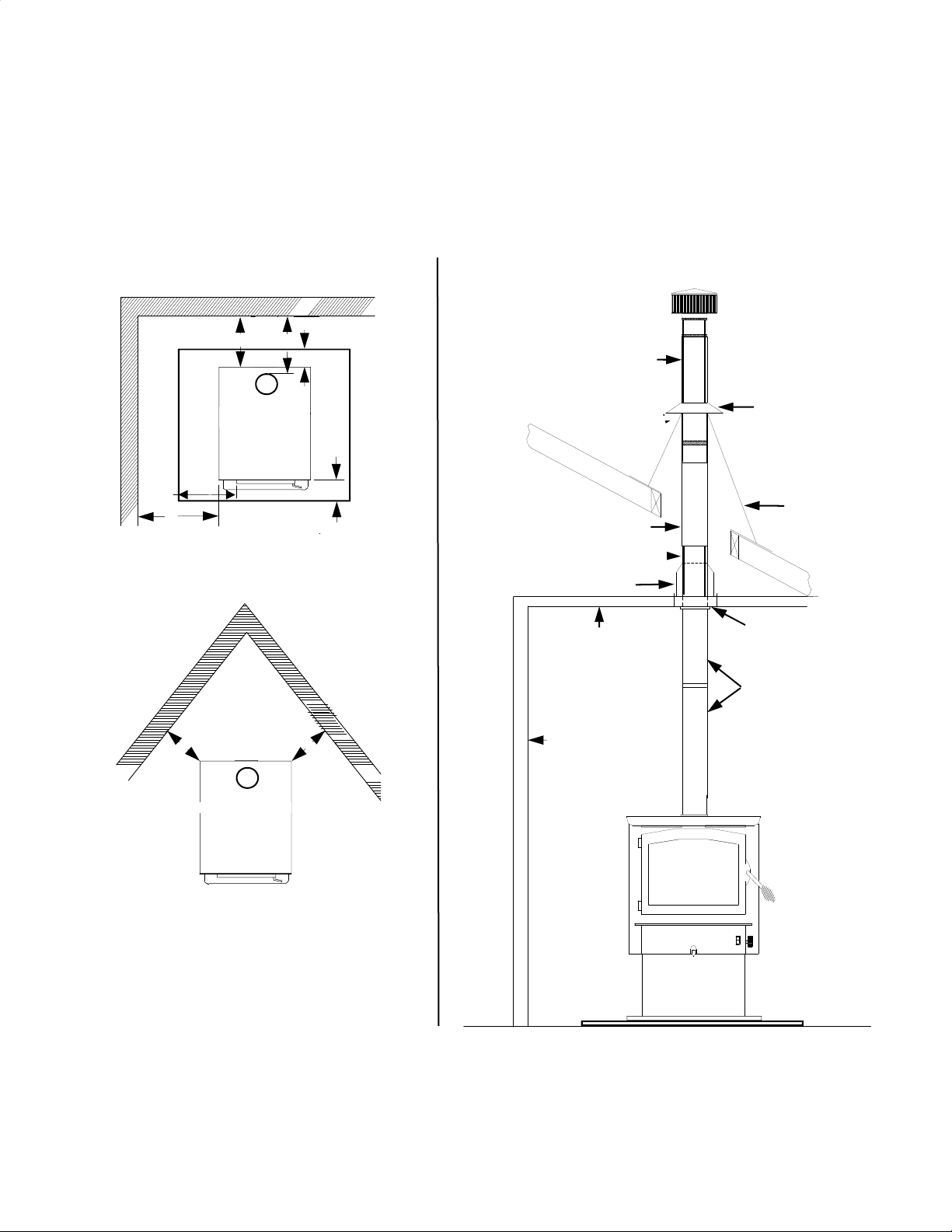
Figure 1
Chimney
This model is designed for connection to any listed 2100º UL103 HT chimneys and parts.
This room heater must be converted to (1) a chimney complying with the requirements for
Type HT chimneys in the Standard for chimneys, Factory-Built, Residential, Type and
Building Heating Appliance, UL 103, or (2) a code approved masonry chimney with a flue
liner.
Page 4

Floor Protection:
Floor protection must be 3/8” minimum thickness non-combustible material or equivalent.
How to use alternate materials and how to calculate equivalent thickness
An easy means of determining if a proposed alternate floor protector meets requirements listed
in the appliance manual is to follow this procedure:
1. Convert specification to R-value:
R-value is given—no conversion is needed.
K-factor is given with a required thickness (T) in inches:
C-factor is given: R=1/C
2. Determine the R-value of the proposed alternate floor protector.
Use the formula in step (1) to convert values not expressed as “R”
For multiple layers, add R-values of each layer to determine the overall R-value.
3. If the overall R-value of the system is grater than the R-value of the specified floor protector, the alternate is acceptable.
Example:
The specified floor protector should be 3/4” thick material with a K-factor of 0.84.
The proposed alternate is 4” brick with a C-factor of 1.25 over 1/8” mineral board with a
K-factor of 0.29.
Step (a): Use formula above to convert specification to R-value. R= 1/K x T = 1/0.84 x .75 =
0.893
Step (b): Calculate R of proposed system. 4” brick of C=1.25, therefore Rbrick = 1/C = 1/1.25
=0.80 1/8” mineral board of K = 0.29, therefore Rmin.bd. =1/029 x0.125 = 0.431
Step (c): Compare proposed system R of 1.231 to specified R of 0.893. Since proposed
system R is greater than required , the system is acceptable.
Definitions:
Thermal conductance = C =
Btu
(hr)(ft²)(°F) (m²)(°K)
=
W
Thermal conductance = K =
(Btu)(inch)
(hr)(ft²)(°F) (m)(°K) (hr)(ft)(°F)
=
W
=
(Btu)
Thermal conductance = R =
(ft²)(hr)(°F)
Btu W
(m²)(°K)
=
Install in accordance with 24 CFR, Part 3280 (HUD).
Page 5
PREPARING THE ROOM HEATER LOCATION
1. Select an installation location that will give the best airflow from the front of the heater to
the remainder of the home.
2. Place the protective floor pad in position.
3. Place the unit on the pad making sure the minimum clearance specifications are met.
4. If connecting to an existing masonry flue, first ensure that the flue conforms to the NFPA-
211 Code and/or consult your local code for proper procedures.
NOTE: This model is designed for connection to: any Listed 2100° UL 103 HT. TYP chimney
also any Listed UL DVL Close Clearance pipe or single wall minimum 24 ga. blued or black
pipe. Follow pipe manufacturer’s instructions carefully.
CHIMNEY
This room heater must be converted to (1) a chimney complying with the requirements for Type
HT chimneys in the Standard for Chimneys, Factory-Built, Residential, Type and Building
Heating Appliance, UL 103, or (2) a code approved masonry chimney with flue liner.
CAUTION: Certain installation types require the use of certain chimney types.
Please follow these instructions exactly.
HOW TO LOCATE CHIMNEY EXIT AND INSTALL
Residential Installation
A. Vertical Exit using (6" Single wall minimum 24 ga. blued or black pipe and any
Listed 2100° UL 103 HT. Chimney)
Without optional close clearance shield, and pipe shield.
NOTE: For minimum clearances (See Page 7, Figure 2).
1. Suspend a plumb bob from the ceiling above the unit so that the weight is hanging in the
center of the flue exit. (A small weight on a string will serve as a plumb bob). Mark the
ceiling where the string is suspended to locate the center of the chimney.
2. After locating the center of the hole, install the ceiling support box, chimney or chimney
connector, flashing and rain cap per the chimney manufacturer’s instructions and local
building codes for installation through combustible walls or ceilings.
3. Now connect the stove and ceiling support box using 6" Single Wall minimum 24 ga.
blued or black pipe (DO NOT USE GALVANIZED PIPE). Connect each section so
the crimped end faces downward and secure each section to each other using at least
three (3) sheet metal screws or rivets. Single wall pipe is to be connected with (3) sheet
metal screws or rivets to connector collar on heater.
(See Page 7, Figure 3).
Page 6
BACK WALL
A. Vertical exit using
pipe
and any listed 2100° UL 103 HT. TYPE Chimney)
(6" Single wall minimum 24 ga. blued or black
Without optional close clearance shield and pipe shield
Model FS 21 minimum clearance to combustibles
SIDE WALL
A B C D E F G
MODEL 21 25”
NOTE: All clearances are to combustibles without close clearance shields and pipe shield, using 6"
Single Wall minimum 24 ga. blued or black pipe and minimum floor protector . The clearances
above may be reduced. Follow NFPA-211 codes if available or follow instructions on (Pages 10,
and 11).
Figure 2.
BACK WALL
F
B
B
E
PROTECTOR PAD
E
A
A
C
C
13" 13" 15.5" 8" 6" 16"
F
D
G
D
G
C
C
Figure 3.
LISTED 2100° UL 103 HT
TYP. CHIMNEY
DO NOT OBSTRUCT
CAULK
RADIATION SHIELD
LISTED 2100° UL 103 HT TYP.
INSTALLATION
CEILING
SIDE
WALL
NEW BUCK
BUCK STOVE
CONTEMPORARY CAP
STORM COLLAR
FLASHING
CEILING SUPPORT
SINGLE WALL
CONNECTOR PIPE
Page 7

HOW TO LOCATE CHIMNEY EXIT AND INSTALL
Residential Installation
B. Vertical Wall Exit using (6" Single Wall minimum 24 ga. blued or black pipe with el-
bow and any Listed 2100° UL HT chimney and Listed 2100° UL HT. T-Box assembly)
Without optional close clearance shields and pipe shield.
NOTE: For minimum clearances (See Page 9, Figure 4).
1. Mark the plumb line on the wall directly behind the center of the heater.
(See Page 9, Figure 5).
NOTE: When using 6" Single Wall minimum 24ga. blued or black pipe
“ maintain 18" minimum clearances" between pipe and ceiling .”
2. Place the vertical portion of the heater pipe and the elbow in position and project a
point onto the plumb line level with the center of the elbow.
3. Measure up so there will be at least 1/4" rise per foot of horizontal connector pipe,
maintaining clearances to the ceiling as noted in (Page 9,Figure 5). This will give you
the center of the hole for the chimney penetration.
4. After locating the center of the penetration, install the tee-box and chimney as per the
chimney manufacturer's specifications.
5. Connect the chimney collar to the tee-box using 6" Single Wall minimum 24 ga. blued
or black pipe. (DO NOT USE GALVANIZED PIPE). Connect each section so the
crimped end faces downward and secure each section to each other using three (3)
sheet metal screws or rivets. Single wall pipe is to be connected with three (3) sheet
metal screws rivets to connector collar on heater.
(See Page 9, Figure 5).
Page 8
 Loading...