

New Buck Corporation FP-32 User Manual

MODEL 32
MAY BE INSTALLED IN A SOLID FUEL BURNING FIREPLACE, AS A
FREESTANDING FIREPLACE OR WITH AN
OPTIONAL WOODEN SURROUND
ON
VENT-FREE
WA RN I N G: If the information in this manual is not followed exactly, a fire or
explosion may result causing property damage, personal injury or loss of life.
− Do not store or use gasoline or other flammable vapors and liquids in the vicinity of this
or any other appliance.
WHAT TO DO IF YOU SMELL GAS
• Do not try to light any appliance.
• Do not touch any electrical switch; do not use any phone in your building.
• Immediately call your gas supplier from a neighbor’s phone. Follow the gas supplier’s
instructions.
• If you cannot reach your gas supplier, call the fire department.
− Installation and service must be performed by a qualified installer, service agency or the
gas supplier.
This is an unvented gas-fired heater. It uses air (oxygen) from the room in which it is installed. Provisions for adequate combustion and ventilation air must be provided. Refer to
section “ Producing Adequate Ventilation” page 12.
This appliance may be installed in an aftermarket, permanently located, manufactured
(mobile) home, where not prohibited by local codes.
This appliance is only for use with the type of gas indicated on the rating plate. This appliance is not convertible for use with other gases.
WARNING
This appliance is equipped for (natural or propane) gas .
Field conversion is not permitted.
INSTALLER: Leave this manual with the appliance.
CONSUMER: Retain this manual for future reference.
Manufacturer: NEW BUCK CORPORATION
P.O. Box 69
8000 Highway 226 South
Spruce Pine, NC 28777
This appliance is intended for supplemental heating.
Revised December 2006


TABLE OF CONTENTS
Page 1
Safety Information and Warnings ........................................................................................ 3
Solid Fuel Burning Fireplace Installation (FP) .................................................................... 6
Freestanding Installation Without or With Optional Pedestal (FS) .................................... 8
Wooden Surround Installation (WS) ................................................................................. 10
Mobile Home Installation ................................................................................................. 11
Producing Adequate Ventilation ........................................................................................ 12
Ventilation Air Indoors ...................................................................................................... 14
Ventilation Air Outdoors ................................................................................................... 15
Placement of Logs ............................................................................................................. 16
Gas Connection .................................................................................................................. 17
Gas Pressure Check ........................................................................................................... 18
Lighting Instructions - (ITT) Millivolt Valve .................................................................... 19
Lighting Instructions - (SIT) Modulating or – (SIT) Manual .......................................... 23
Flame Check ...................................................................................................................... 27
Wiring Diagram ................................................................................................................. 28
Important Safeguards ......................................................................................................... 29
Trouble Shooting ............................................................................................................... 30
Service/Replacement Parts ................................................................................................ 34
Warranty/Owner Registration ........................................................................................... .39

Page 2

SECTION I
Page 3
SAFETY INFORMATION WARNINGS
IMPORTANT: READ THIS OWNER’S MANUAL CAREFULLY AND COMPLETELY
BEFORE TRYING TO ASSEMBLE, OPERATE, OR SERVICE THE APPLIANCE.
IMPROPER USE OF THESE LOGS CAN CAUSE SERIOUS INJURY OR DEATH FROM
BURNS, FIRE, EXPLOSION, AND CARBON MONOXIDE POISONING.
Early signs of carbon monoxide poisoning resemble the flu, with headaches, dizziness, and/or
nausea. If you have these signs, the heater may not be working properly. Get fresh air at once!
Have heater serviced.
Some people-pregnant women, persons with heart or lung disease, anemia, those under the
influence of alcohol, and those at high altitudes-are more affected by carbon monoxide than
others.
CAUTION: Strong drafts, such as a ceiling fan placed directly in front of the heater
(pulling from either direction) may create sooting. Sooting will discolor
walls.
1. The installation must conform with local codes ,or in the absence of local codes, with the
National Fuel Gas Code, ANSI Z223.1/NFPA54.
2. This appliance may be installed in an After-Market* Manufactured (Mobile) Home,
where not prohibited by state or local codes.
* (After-Market: Completion of sale, not for purpose of resale from the manufacturer.)
This appliance is only for use with the type of gas indicated on the rating plate. This
appliance is not convertible for use with other gases.
NOTE: “Producing Adequate Ventilation” page 12.
IMPORTANT:
IS BENEFICIAL, INSTALLING HEATER IN ROOMS WITHOUT ADEQUATE
VENTILATION MAY CAUSE MILDEW TO FORM FROM TOO MUCH MOISTURE.
3. Never install this heater:
♦ in a recreational vehicle, bathroom, bedroom, or any other sleeping quarters
♦ where curtains, furniture, clothing, or other flammable objects are less than 42" from the
front of the heater
♦ in high traffic areas or in windy areas
4. Two models are available. One specific model for propane (LP), and one for natural gas.
Use the correct type gas for your home. Do not convert from one gas type to another.
“WARNING: ANY CHANGE TO THIS HEATER OR ITS CONTROLS CAN BE
DANGEROUS.”
VENT-FREE HEATERS ADD MOISTURE TO THE AIR. ALTHOUGH THIS

5. If this heater is used with propane gas, do not place propane supply tank (s) inside any structure.
Page 4
6. What To Do IF You Smell Gas:
Shut off gas supply.
- Do not try to light any appliance.
- Do not touch any electrical switch; do not use any phone in your building.
- Immediately call your gas supplier from a neighbor’s phone.
Follow the gas supplier’s instructions.
- If you cannot reach your gas supplier, call the fire department.
7. When operated for the first time, the logs may emit a “paper burning” smell. This smell will
gradually diminish and will be totally eliminated after the first few hours of operation. Run the gas
logs with the flue damper open during this time. Do not use blower at this time.
8. “This heater shall not be installed in a confined space or unusually tight construction unless
provisions are provided for adequate combustion and ventilation air.” See “Producing
Adequate Ventilation”, page 12.
9. Surface of gas logs becomes very hot when operating. Keep children and adults away from hot
surface. Gas logs will remain hot for sometime after shutdown. Allow surface to cool before
touching.
10. Do not place clothing or other flammable material on or near the appliance.
11. If equipped, fresh air damper must be closed.
12. Keep appliance area clean and free from combustible materials, gasoline, and other flammable
flammable vapors and liquids. .
13. If burner shuts off, do not relight until you provide fresh outside air. If burner continues to shut off,
have unit serviced.
14. Do not use this heater if any part has been under water. Immediately call qualified service
technician to inspect the room heater and to replace any part of the control system and any
gas control which has been under water.
15. Turn off the heater and let cool before servicing.
16. These logs are made of bonded fiber. When removing logs and base, do not damage the bonded
material. If the material is damaged extensively, loose fiber dust could be emitted into the air.
17. Any safety screen or guard removed for servicing an appliance must be replaced prior to
operating the heater.
18. This appliance is intended for supplemental heating.
19.
“WARNING: Any change to this heater or its controls can be dangerous.”
20. Installation and repairs should be performed by a qualified service person. The appliance
should be inspected before use and at least annually by a professional service person. More
frequent cleaning may be required due to excessive lint from carpeting, bedding material, etc.
It is imperative that control compartments, burners and circulating air passageways of the
appliance be kept clean.

21. All heater screens must be kept clean when operating the gas logs.
Page 5
”WARNING: Failure to keep the primary air opening (s) of the burner (s) clean may result
22. .
in sooting and property damage.”
23. Do not use this heater for burning trash or cooking. Never place matches, paper, garbage, or any
other material on top of logs or into the flames.
24. Do not install or operate this heater in areas where impurities in the air exist (such as tobacco
smoke or heavy cooking grease). Particles from impurities may discolor walls.
25. Due to high temperatures, the appliance should be located out of traffic and away from
furniture and draperies.
26. Children and adults should be alerted to the hazards of high surface temperature and should
stay away to avoid burns or clothing ignition.
27. Young children should be carefully supervised when they are in the same room with the
appliance.
28. An unvented room heater having an input rating of more than 10,000 Btu per hour shall not
be installed in a bedroom or bathroom.
29. The appliance and its appliance main gas valve must be disconnected from the gas supply
pipping system during any pressure testing of that system at test pressure in excess of 1/2
psi (3.5 kPa).
30. The appliance must be isolated from the gas supply pipping system by closing its equipment
shut-off valve during any pressure testing of the gas supply piping system at test pressures
equal to or less than 1/2 psi (3.5 kPa).
31. “
WARNING: Do not allow fans to blow directly into fireplace. Avoid any drafts that alter
burner flame patterns.”
32. “
WARNING: Do not use a blower insert, heat exchanger insert or other accessory not
approved for use with this heater.”
33. Adequate clearances around air openings. Nothing may be placed over any of the air openings on
this appliance, or can any of the air openings be modified in anyway.
34. “Trim panels or surrounds shall not seal ventilation openings in the fireplace.”
35. “A fireplace screen must be in place when the appliance is operating and, unless other
provisions for combustion air are provided, the screen shall have opening(s) for introduction
of combustion air.

MASONRY INSERT INSTALLATION/ SOLID
Page 6
FUEL BURNING FIREPLACE MODEL 32 (FP)
1. The Model 32 (FP) may be installed in a masonry fireplace.
Minimum fireplace dimensions: 25 1/2" high, 21-1/2" wide, 13" deep.
CEILING
“WARNING: Before installing in a
solid-fuel burning fireplace, the chimney flue and firebox must be cleaned of
soot, creosote, ashes and loose paint by
a qualified chimney cleaner.”
NOTE: Any outside air ducts and / or
ash dumps in the fireplace shall be permanently closed at time of appliance
installation.
WALL
LEFT SIDE
7"
5”
13"
42”
24"
20"
16”
RIGHT SIDE
21-1/2"
FRONT
24” TO COMBUSTIBLES
25-1/2"
Figure 1
12"
“WARNING: Any glass doors shall be
fully opened when appliance is in operation.”
Your new Buck Vent-Free gas heater may be installed in a Residential or *After-Market Mobile
Home, where prohibited by state or local codes.
*After-Market: Completion of sale. Not for purpose of resale from the manufacturer.
This appliance is for use with the type of gas indicated on the rating plate. Not convertible
for use with other gases.
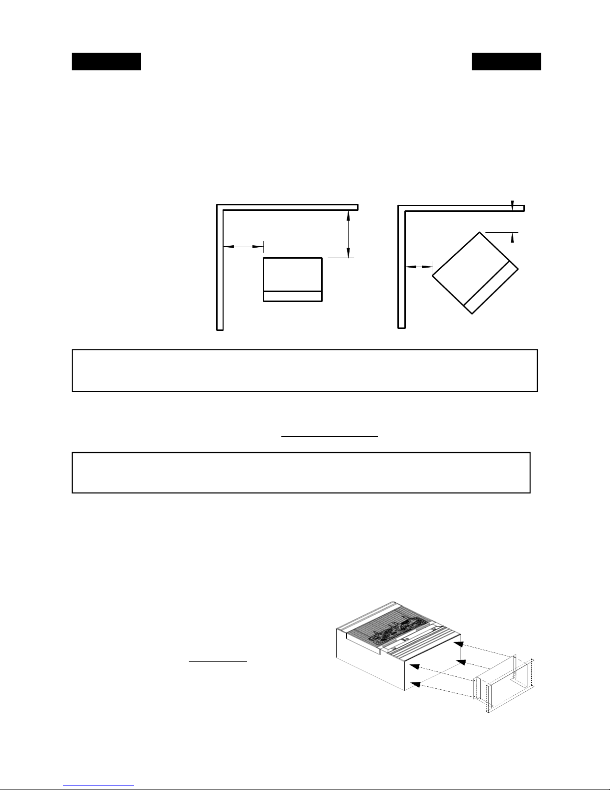
2. Minimum dimensions sidewall and mantel:
Sidewall-not less than 5" See Figure 1.
Mantel-not less than 16" See Figure 1.
3. Center Model 32 in masonry fireplace. Position front of heater even with front of fireplace
chamber if possible.
4. Place side trim panels flat against the fireplace. Draw a vertical reference line along the
inside edge of the trim panel.
5. Place top trim panel on top of unit. Draw reference line for mounting on lower edge of pane
NOTE: The installer of this appliance must mechanically (peel and stick) attach the marking
supplied with this unvented appliance before installing to the inside of the firebox of the solidfuel burning fireplace or listed ventless firebox enclosure into which the unvented fireplace insert is installed. See the example of the marking on page 18 of this manual.
CAUTION: Cutting any sheet-metal parts of the solid-fuel burning fireplace or listed ventless
enclosure in which the unvented fireplace is to be installed is prohibited.
NOTE: “If the factory-built fireplace has no gas access hole(s) provided, an access hole of 1.5
inch (37.5) diameter or less may be drilled through the lower sides or bottom of the firebox in a
proper workmanlike manner. This access hole must be plugged with non-combustible insulation
after the gas supply line has been installed.”
“Refractory, glass doors, screen rails, screen mesh and solid-fuel log grates (if applicable) can
be removed from the fireplace before installing the unvented fireplace insert.”
“Smoke shelves shields and baffles may be removed if attached by mechanical fasteners.”

6. Slide the unit out and install the trim panels with a drill or screw gun. (Self tapping screws
Page 7
provided).
NOTE: Make sure the gas supply line is hooked up at this time, and check for leaks at the
connection using soap and water.
CAUTION: Do Not use an open flame to check for leaks.
7. Place logs on the burner base as shown on page 16.
8. For gas hookup and pressure tap test, see instructions on pages 17 & 18.
NOTE: When operated for the first time, the logs and paint may emit a “paper burning smell”.
This smell will gradually diminish after a few hours of operation. Run the heater with the flue
damper, windows or doors, open during this time. DO NOT use blower at this time.
FREESTANDING INSTALLATION
Page 8
MODEL 32 (FS)
1. Determine the exact location of your gas heater.
NOTE: Due to high temperatures, this heater should be located out of traffic areas and away
from furniture and draperies.
NOTE: For safe installation the minimum clearances must be met. See Figure 2. For floor
protector, see last paragraph, page 8.
NOTE: Clearance form
top of appliance to ceiling is 42”. (Not shown
in figure 2)
WALL
NOTE:
DIMENSIONS SHOWN ARE
MINIMUM CLEARANCE TO
COMBUSTIBLE WALL.
5"
4"
WALL
4"
4"
VE
STOVE
Figure 2
CAUTION: THE INSTALLATION MUST CONFORM TO LOCAL CODES. IN THE
ABSENCE OF LOCAL CODES, INSTALLATION MUST CONFORM WITH THE NATIONAL
FUEL GAS CODE,ANSI Z223.1/NFPA54.
NOTE: See page 17 for “Gas Connection” and page 18 for “Pressure Check”.
2. Check gas type. Use only the type of gas indicated on the valve rating plate. If the type of gas listed
on the plate is not your type of gas supply, DO NOT INSTALL.
model. Position logs as shown on page 16. Position screen before leaving heater unattended.
Contact your dealer for proper
WARNING: YOUNG CHILDREN SHOULD BE CAREFULLY SUPERVISED WHEN THEY
ARE IN THE SAME ROOM AS THE HEATER. DO NOT PLACE CLOTHING OR OTHER
FLAMMABLE MATERIAL ON OR NEAR THE HEATER.
NOTE: When the appliance is installed directly on carpeting, tile or other combustible material, other
than wood flooring, the appliance shall be installed on a metal or wood panel extending the full width
and depth of the appliance.
Optional Pedestal (Part#FAP11) Instructions: Lay the heater on its back (use a drop-cloth to protect
the back of the heater and the surface of your flooring). Place pedestal against the bottom of the heater.
Center pedestal from left to right and from front to rear. Mark the holes on the angle of the top of the
STO
pedestal onto the bottom of the heater. Lay the pedestal aside.
Drill the marks made onto the heater with a 1/8” bite (not provided). Replace the pedestal and secure with the screws provided. Next stand the heater to the upright position. Place the
heater in the desired location following the clearances above in
figure 2. Note: At this point you may need
tal to the floor with screws or an “ell” bracket (not provided)
for safety concerns. Next hook up the gas supply line following the instructions in this manual completely.
to secure the pedes-

ALCOVE INSTALLATION
Page 9
CAUTION:
1. For clearances, see Figure 3. The minimum clearances must be met.
2. For “Installation and Gas Connection”, see page 17.
READ ENTIRE MANUAL BEFORE INSTALLING HEATER.
FOR YOUR SAFETY:
WHAT TO DO IF YOU SMELL GAS
-Do not try to light appliance.
-Do not touch any electrical switch.
-Do not use telephone in building.
-Call your gas supplier immediately, from a neighbor’s phone. Follow the gas supplier
instructions.
-If you cannot reach your gas supplier, call the Fire Department.
-Do not store or use gasoline or any other flammable vapors or liquids in the vicinity of
this appliance or any other appliance.
WARNING: DO NOT USE THIS ROOM HEATER IF ANY PART HAS BEEN UNDER
WATER. IMMEDIATELY CALL A QUALIFIED SERVICE TECHNICIAN TO INSPECT
THE ROOM HEATER AND TO REPLACE ANY PART OF THE CONTROL SYSTEM
AND ANY GAS CONTROL WHICH HAS BEEN UNDER WATER.
WARNING: IMPROPER INSTALLATION, ADJUSTMENT, ALTERATION,
SERVICE, OR MAINTENANCE CAN CAUSE PROPERTY DAMAGE, PERSONAL
INJURY OR LOSS OF LIFE. INSTALLATION AND SERVICE MUST BE PERFORMED
BY A QULIFIED INSTALLER, SERVICE AGENCY OR THE GAS SUPPLIER.
“WARNING: ANY CHANGE TO THIS HEATER OR ITS CONTROLS CAN BE
DANGEROUS.”
NOTE: The depth of the alcove must allow a 4" minimum clearance at the rear. The width of
the alcove must allow a 5” clearance on the right side and the left side. The height of the alcove
must allow for a 10” clearance form the top of the heater to the ceiling of the alcove. The front
edge of the heater must meet the front of the alcove, and have a minimum of 24” to any
combustible material.
WALL
NOTE:
DIMENSIONS SHOWN ARE
MINIMUM CLEARANCE TO
COMBUSTIBLE WALL.
5"
FLOOR
PROTECTOR
10"
4"
STOVE
Figure 3

INSTALLATION OF MODEL 32 (WS)
Page 10
A. Determine the desired location for your heater and wooden surround. See “Freestanding
B To install metal filler strips to the surround (after completing step 2 of surround assembly),
C Make sure wooden mantel is in correct position. Place the heater into the surround. Connect gas line
D Make sure you leave 1/4" space between the metal filler strip and the top and sides of the heater.
NOTE: You will need to heave 1/2" space between the back of the wooden mantel and an adjacent
combustible wall.
NOTE: If a masonry hearth is built up under front bottom of heater, and you do not use the hearth
provided with the wooden surround, you must have 12" of non-combustible material from front bottom
edge of heater.
WITH OPTIONAL WOODEN SURROUND(KIT#PA-KDM32)
Installation” for minimum clearances.
position the wooden mantel over the unit, centering it up in the cabinet. Place the metal filler strips
to the side of the cabinet, allowing 1/4" air space between the strips and side of the cabinet. Make a
light pencil mark on strip. Remove the wooden mantel from around cabinet. Align the pencil mark
with the inner edge of the cabinet from back side. Using the screws provided with heater, fasten
strips to the back of the mantel.(At this point complete steps 3 and 4 of surround assembly)
to the heater, following all the instruction in this manual completely
You will also want to position the heater so you have 5 1/2" from outer lip of hot air vent to the
pieces of metal strips, not the wooden face of the mantel. See Figure 4.
5-1/2"
METAL STRIP
ON
Figure 4
(WS) ASSEMBLY INSTRUCTIONS
Tools Needed: Medium Phillips Screwdriver
Step 1: Lay out all components. (See diagram 1)
Step 2: Assemble end panels (A & B) to top front rail ( C ).(See section “B” above on this page)
Step 3: Stand end panels and top front rail onto hearth and fasten down with screws provided (See diagram 1).
NOTE: Position back of end panels with back of hearth centering assembly from each end. Install front
screws first, then pull back towards the inside to square the surround (mantel) up. Install screws through
back holes.
Step 4: Place top onto surround, flush with back and equal on each end. Secure both ends and middle
with screws provided.
CONTINUED ON PAGE 11
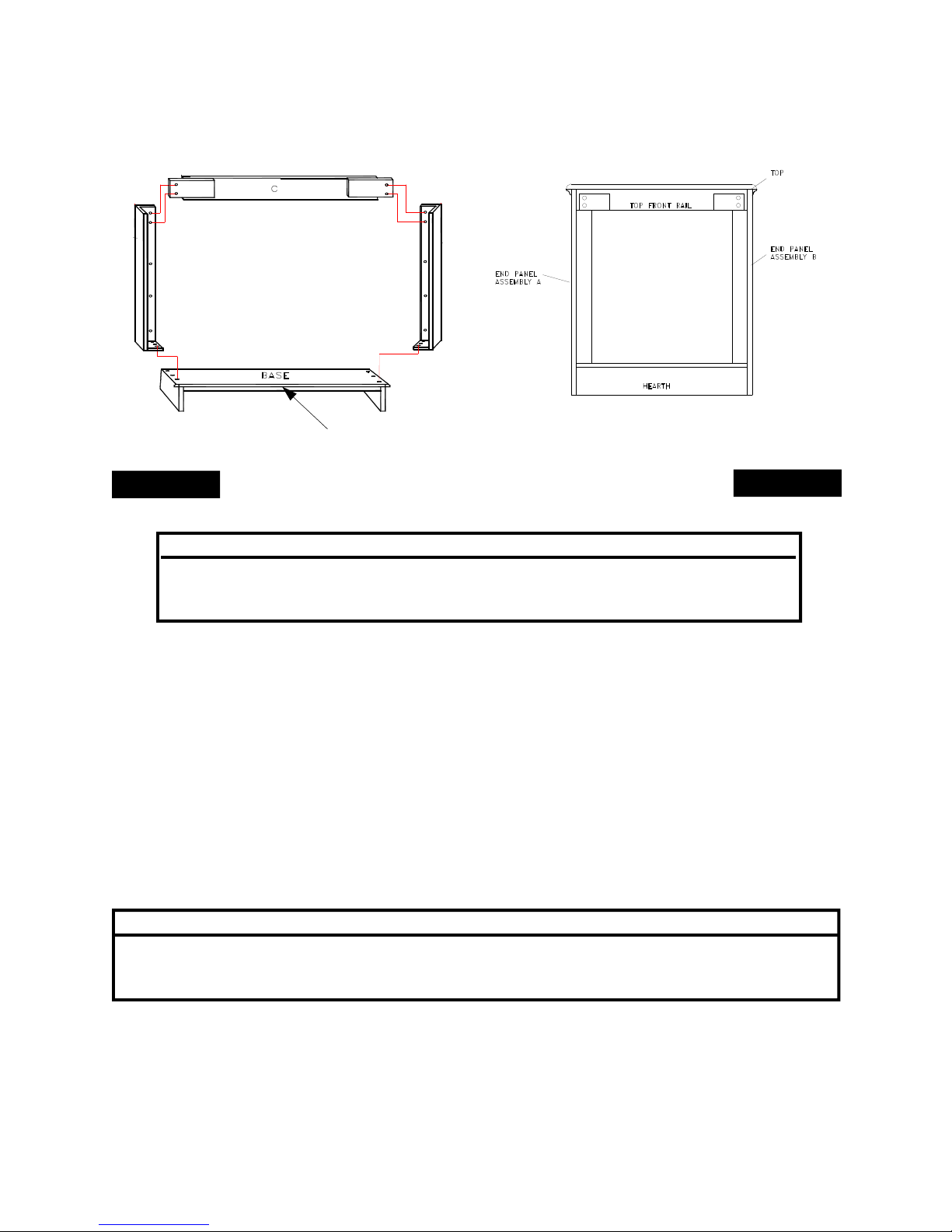
EXPLODED VIEW OF MODEL 32 (WS)
Page 11
WOODEN SURROUND BASE (HEARTH)
(SHOWN AS VIEWED FROM REAR OF SURROUND)
INSTALLATION IN RESIDENTIAL
OR AFTER-MARKET MOBILE HOMES
A QUALIFIED SERVICE TECHNICIAN MUST INSTALL THIS HEATER.
CHECK FOR STATE AND LOCAL CODES CONCERNING INSTALLATION
CHECK GAS TYPE:
THIS APPLIANCE IS ONLY FOR USE WITH THE TYPE OF GAS INDICATED ON THE
RATING PLATE. THIS APPLIANCE IS NOT CONVERTIBLE FOR USE WITH OTHER
GASES.
INSTALLATION SUPPLIES:
Before installing the heater, gather the following materials:
- external regulator - ground joint union
(supplied by installer for propane) - sediment trap
- piping (check local codes) - tee joint
- manual shutoff valve* - pipe wrench
- test gauge connection* - sealant (resistant to LP gas)
* An C.S.A. design-certified manual shutoff valve with 1/8" NPT tap is an acceptable alternative to test
gauge connection. Purchase the optional C.S.A. design-certified manual shutoff valve from your dealer.
MAINTAIN THE MINIMUM CLEARANCES SHOWN THROUGHOUT THIS MANUAL. IF
POSSIBLE, PROVIDE GREATER CLEARANCES FROM FLOOR, CEILING, AND
ADJOINING WALL.
NOTE: See “Producing Adequate Ventilation” page 12.
.THIS APPLIANCE MAY BE INSTALLED IN AN AFTERMARKET*, PERMANENTLY
LOCATED, MANUFACTURED (MOBILE) HOME, WHERE NOT PROHIBITED BY LOCAL
CODES.
*After Market: Completion of sale, not for the purpose of resale from the manufacturer.
REQUIREMENTS.
NOTICE:
WARNING
 Loading...