

New Buck Corporation DV23ZC User Manual
OPERATIONS MANUAL FOR THE MODEL DV23ZC
DIRECT VENT ZERO CLEARANCE GAS FIREPLACE
APPROVED FOR MOBILE HOME INSTALLATION
WARNING:
explosion may result causing property damage, personal injury, or loss of life.
-DO NOT STORE OR USE GASOLINE OR OTHER FLAMMABLE VAPORS AND
LIQUIDS IN THE VICINITY OF THIS OR ANY OTHER APPLIANCE.
-WHAT TO DO IF YOU SMELL GAS
* Do not try to light any appliance.
* Do not touch any electrical switch; do not use any phone in your building.
* Immediately call your gas supplier from a neighbor's phone.
Follow the gas supplier's instructions.
* If you cannot reach the gas supplier, call the fire department.
-Installation and service must be performed by a qualified installer, service agency, or the gas
supplier.
-Save this manual for future reference.
New Buck Corporation Revised Aug/2008
P.O. Box 69
200 Ethan Allen Drive
Spruce Pine, NC 28777
If the following information in this manual is not followed exactly, a fire or


TABLE OF CONTENTS
Introduction .......................................................................................................................... 3
Specifications ....................................................................................................................... 3
Installation ........................................................................................................................... 5
Location and Clearance ....................................................................................................... 5
Assembly Steps-Overview ................................................................................................... 5
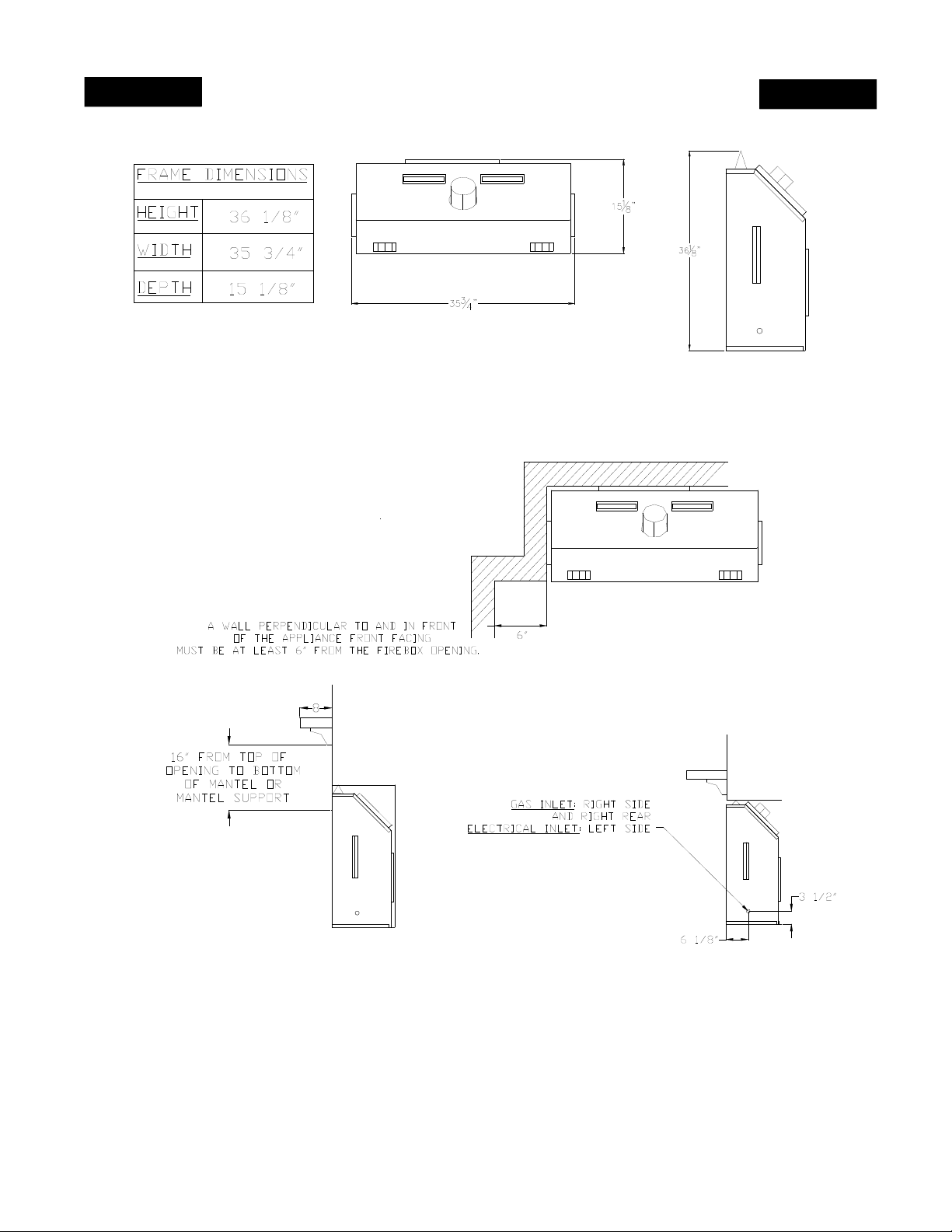
Appliance and Framing Dimensions ................................................................................... 6
Exterior Vent Locations and Restrictions ............................................................................ 9
Minimum-Maximum Vent Length Requirement ............................................................... 10
Vent Assembly ................................................................................................................... 11
Horizontal Termination ..................................................................................................... 11
Vertical Termination .......................................................................................................... 14
High Altitude ..................................................................................................................... 17
Gas Valve Connection ....................................................................................................... 18
Gas Pressure Checks .......................................................................................................... 18
Operating Instructions ....................................................................................................... 19
Lighting Instructions .......................................................................................................... 19
Shut Off Procedure ........................................................................................................... 21
Log Installation .................................................................................................................. 22
Pilot and Flame .................................................................................................................. 23
Glass Door Installation ...................................................................................................... 23
Wiring Diagrams ............................................................................................................... 24
Accessories or Options ...................................................................................................... 25
Maintenance ....................................................................................................................... 26
General Maintenance ......................................................................................................... 26
Replacement Parts ............................................................................................................. 27
Warranty ............................................................................................................................ 30
1

2

This instruction manual will help you obtain a safe, efficient, dependable installation for your appliance
and vent system. Please read and understand these instructions before beginning your installation.
The model DV23ZC is a sealed combustion, air circulating gas appliance designed for residential and
mobile home applications. The appliance must be installed with Dura-Vent GS vent system that is
routed to outside atmosphere. It is also listed for bedroom installations.
This appliance is designed to operate on natural or propane gas. A millivolt gas control valve with piezo
ignition system provides safe, efficient operation. No external electrical power is required to operate the
gas valve and burner. 120VAC is required to operate the room air fan.
This appliance complies with National Safety Standards and is tested and listed by (ITS) Intertek Testing
Services (Warnock Hersey) to ANSI Z21.88-2002 and CSA 2.33-2002 ISA CAN/CGA-2.17-M91Appliance for use at high altitudes. Installation must conform to local codes. In the absence of local
codes, installation must comply with the current
(In Canada, installation must comply with the current CAN-1B149 installation code.)
Approved for manufactured (Mobile) home installation. For mobile housing, Title 24 CFR, Part
3280 or when such a standard is not applicable, the standard for manufactured home installation, ANSI /
NCBS A225.1 or standard for gas equipped recreation vehicles and mobile housing, CSA Z240.4.
INTRODUCTION
National Fuel Gas Code, ANSI Z223.1/NFPA54..
DO NOT ATTEMPT TO ALTER OR MODIFY THE CONSTRUCTION OF THE
APPLIANCE OR ITS COMPONENTS. ANY MODIFICATION OR ALTERATION
MAY VOID THE WARRANTY, CERTIFICATION AND LISTINGS OF THIS UNIT.
SPECIFICATIONS - MODEL DV23ZC
GAS: NAT. L.P.
HIGH FIRE 22,000 BTU 22,000 BTU
LOW FIRE 14,000 BTU 17,600 BTU
GAS INLET PRESSURE: NAT. L.P.
MAX. INPUT 10.5" W.C. 14.0" W.C.
MIN. INPUT *5.0" W.C. 10.5" W.C.
*5.0" W.C. is minimum inlet gas supply pressure for the purpose of input adjustment.
MANIFOLD PRESSURE: NAT. L.P.
3.5" W.C. 10.0" W.C.
STEADY STATE EFFICIENCY:
NATURAL GAS 77.10%
L.P. GAS 77.10%
FLUE VENT 4" INNER, 6" OUTER; DURA-VENT MODEL GS
SAFETY AGA CERTIFIED PILOT GENERATOR, MILLIVOLT
SYSTEM ACTIVATED WITH SWITCH OR THERMOSTAT.
3
NOTE: Installation and repair should be performed by a qualified service person. The
appliance should be inspected annually by a qualified professional service person. More
frequent inspections and cleanings may be required due to excessive lint from carpeting,
bedding material, pet hair, etc. It is imperative that the control compartment, burners and
circulating air passage ways of the appliance be kept clean.
Provide adequate clearances around air openings and adequate accessibility clearance for
service and proper operation. Never obstruct the front openings of the appliance.
This appliance is designed to operate on natural or propane gas only. The use of other fuels or
combination of fuels will degrade the performance of this system. The gas input of this
appliance is 22,000 BTU/HR for natural gas and 22,000 BTU/HR for propane gas models.
Children and adults should be alerted to the hazards of high surface temperatures and
should stay away to avoid burns or clothing ignition. Young children should be carefully
supervised when they are in the same room as the appliance. Clothing or other flammable
material should not be placed on or near the appliance.
Any safety screen or guard removed for servicing this appliance must be replaced prior to
operating the appliance.
WARNING
Do not operate with the glass door removed, cracked, or broken. Replacement of the glass
should be done by a licensed or qualified service person.
Do not use this appliance if any part has been under water. Immediately call a qualified service
technician to inspect the appliance and to replace any parts of the control system and any gas
controls which have been under water.
Minimum inlet gas pressure is 5" Water Column for natural gas and 10.5" Water Column for
propane for the purpose of input adjustment.
Maximum inlet gas supply pressure is 10.5" Water Column for natural gas and 14" Water
Column for propane.
The appliance must be isolated from the gas supply piping system (by closing its individual
manual shut-off valve) during any pressure testing of the gas supply piping system at test
pressures equal to or less than 1/2 psig (3.5kPa).
This appliance and its individual shut-off valve must be disconnected from the gas supply
piping system during any pressure testing of that system at pressures in excess of 1/2 psig
(3.5kPa).
4

GENERAL INFORMATION
LOCATION AND CLEARANCE
Make sure your installation location provides adequate combustion and ventilation air.
In selecting the location, the aesthetic and functional uses of the appliance are primary concerns.
However, vent system routing to the exterior and access to the fuel supply are also important.
Consideration should be given to traffic ways, furniture, draperies, etc., due to elevated surface
temperatures. The location should also be free of electrical, plumbing or other heating/air conditioning ducts. Be sure to maintain adequate clearances around air openings into combustion
chamber.
The appliance should be mounted on a fully supported base extending the full width and depth
of the unit. The appliance may be located on or near conventional construction materials.
However, if installed on combustible materials, such as carpeting, vinyl tile, etc., a metal or
wood barrier covering the entire bottom surface must be used.
Right and left sides of the unit are determined when standing in front of the unit.
Minimum clearance to combustibles: sides and back - 0", floor - 0" , adjacent wall to Front 6".
Minimum clearance to combustibles for the vent system is 2" when passing through a wall or
chase.
ASSEMBLY STEPS—OVERVIEW
The typical sequence of installation follows. However, each installation is unique resulting in
variations to those described.
1. Construct framing and position the appliance.
2. Route gas supply line and bring in electrical service line to appliance location.
3. Install vent system.
4. Make connection to gas supply and electrical service.
5. Install the log assembly.
6. Install the remote thermostat (optional).
7. Test fire the burner.
8. Install glass panel.
9. Finish enclosure walls and trim.
5
INSTALLATION
Figure 1
6

*
SUPPLIED BY MANUFACTURER
INTERIOR HORIZONTAL
MINIMU M INSTALLATION
NOTE:
NOTE:
NOTE: You may replace or
*
cover this piece of material with a
more decorative non-combustible
material when the unit is installed.
Figure 2
*
SUPPLIED BY MANUFACTURER
INTERIOR VERTICAL
INSTALLATION WITH
A MAXIMU M 42' RISE .
7

INSTALLATION
GENERAL INFORMATION
Remove the shipping carton. Make sure the unit is not damaged. Lift the top louver and remove
three (3) nuts at the upper left, right, and center of the glass frame. Also, open louver at bottom
and remove the three (3) nuts. Set the door aside and protect from inadvertent damage. Retain
nuts for reassembly. Next, carefully remove the box of logs inside the appliance and set these
aside.
1. Framing - Maintain dimensions for the appliance enclosure as illustrated in Figure 1.
2. Gas Supply - These units are equipped with pipe supply access holes at the right side and
right rear facing unit.
3. Position appliance into framing - DO NOT secure with nails at the nailing tabs at top front
corners until venting installation is complete.
4. Vent system — NOTE: (The Model No. DV23ZC must be vented using the Simpson-DuraVent Direct Vent Gas 4" inside 6" venting system.) All warranties will be voided and
serious fire, health, or other safety hazards may result from any of the following actions:
Installation of any damaged components not manufactured or approved by Simpson-DuraVent; failure to meet all clearance requirements; failure to properly twist-lock and seal all
components.
Each section of Dura-Vent-GS flue system must be properly sealed to prevent the possibility of
leakage. This is accomplished by using high temperature silicone sealant. Apply a bead of
sealant around the bell section of the inner pipe prior to joining the pieces together. The outer
pipe joint may be sealed with metal foil tape or with silicone sealant.
WARNING
Always maintain required clearances (air spaces) to combustibles to prevent a fire hazard. Do
not fill air spaces with insulation. Check installation instructions for minimum clearance
requirements between the outer walls of the vent pipe and nearby combustible surfaces. Be sure
to check the vent termination clearance requirements from decks, windows, soffits, gas
regulators, air supply inlets, and public walkways, as specified in these installation instructions
and local building codes. (See page 9.) The gas appliance and vent system must be vented
directly to the outside of the building, and never attached to a chimney serving separate solid
fuel or gas burning appliances. Each direct vent gas appliance must have its own separate vent
system. Common vent systems are prohibited.
5. Remote Wall Switch or Thermostat or Remote Control - This appliance can be switched on
or off using one of several devices: 1). Appliance ON/OFF switch, 2) Wall Mounted Remote
Wall Switch, 3) Remote Wall Thermostat, or 4) Wireless Remote Control.
6. Connecting gas line — make gas line connections. All codes require a shut-off valve
mounted in the supply line. See Figure 15.
The flex line method is acceptable in the United States. However, Canadian requirements vary
depending upon locality. Installation must be in compliance with local codes.
8
 Loading...