

New Buck Corporation COMBO COAL & WOOD STOVE Owner's Manual
COMBO COAL & WOOD STOVE
OWNER'S MANUAL
FOR BURNING BITUMINOUS / ANTHRACITE COAL OR
HARD, SEASONED NATURAL WOOD
SAFETY NOTICE
IF THIS HEATER IS NOT PROPERLY INSTALLED, A HOUSE FIRE MAY RESULT. FOR
YOUR SAFETY, FOLLOW THE INSTALLATION INSTRUCTIONS. THE AUTHORITY HAVING JURISDICTION ( SUCH AS MUNICIPAL BUILDING DEPARTMENT, FIRE DEPARTMENT, FIRE PREVENTION BUREAU, ect.) SHOULD BE CONSULTED BEFORE INSTALLATION TO DETERMINE THE NEED TO OBTAIN A PERMIT. KEEP THESE INSTRUCTIONS
FOR FUTURE USE.
TESTED AND LISTED TO UL 1482 BY: ITS/WARNOCK HERSEY, MIDDLETON, WI
NEW BUCK CORPORATION -
SPRUCE PINE, NC 28777
MANUFACTURED BY
Nov 2009


TABLE OF CONTENTS
Important Installation Instructions………………………………………...…………………...……..2
Introduction……………………………………………….……………………………………...…...3
Installation………………………………………………...……………………………………….....4
Chimney Connection - Chimney…………………………………………………………….……....5
Thimble - Connection to a Metal Prefabricated Chimney……………………………………...........7
Methods of Installations………………………………………………………………………………8
Preparing Room Heater Location…………………………………………………………...……......9
A) Rear Exit Into Flue using (6" Single Wall Pipe minimum 24 ga. blued
or black pipe) or (6" DVL Close Clearance Pipe)……………………………………………..10
B) Rear Exit to Vertical then to Horizontal into Flue using (6" Single Wall Pipe
minimum 24 ga. blued or black pipe with Elbows) or (6" DVL Close
Clearance Pipe with Elbows)…………………………………………………………………..13
C) Rear exit into Masonry Fireplace using (6" Single Wall pipe, minimum 24 ga.
blued or black pipe)……………………………………………………………………………..16
D) Rear Exit to Vertical Ceiling Exit using (6" Single Wall minimum 24 ga. blued
or black pipe with Elbow) or (6" DVL Close Clearance Pipe with Elbow) and
any (Listed 2100° UL 103 HT Chimney)…………………………………………………..…..18
E) Rear Exit Through Wall, Exterior Chimney Outside Residence using (6"
Single Wall pipe minimum 24 ga. blued or Black pipe) or (6" DVL Close
Clearance Pipe) and any (Listed 2100° UL. HT chimney and Listed 2100°
UL HT T-Box assembly)……………………………………………………………….……….20
Reduced Wall Clearances………………………………………………………………………...….22
Cautions………………………………………………………………………………………….…..23
Operation For Burning Wood Fuel………………………….…………………………………….....24
Operation For Burning Coal Fuel……….…………………………………………………………...26
Shaker, Feed Door, and Ash Dump Door Handle……………………………..………………….….28
Maintaining a Fire…………………………………………………………………………………...29
Ash Removal and Disposal……………………………………………………………………….....29
Blower and installation( Optional )……………………………………………...…………………..30
.
Warranty………………………………………………………………………………………….….31
Page 1
INSTALLATION, OPERATION, AND
MAINTENANCE INSTRUCTIONS
COMBO COAL & WOOD STOVE
READ THIS FIRST
IMPORTANT INSTRUCTIONS
WARNING
THESE UNITS GENERATE A LOT OF HEAT, SO TREAT THEM WITH CARE. HOT
WHILE IN OPERATION! KEEP CHILDREN, CLOTHING AND FURNITURE AWAY.
CONTACT MAY CAUSE SKIN BURNS. READ ALL INSTRUCTIONS BEFORE
INSTALLING AND USING THE APPLIANCE. FAILURE TO FOLLOW INSTRUC TIONS MAY RESULT IN PROPERTY DAMAGE, BODILY INJURY, OR EVEN DEATH.
SAVE THESE INSTRUCTIONS FOR FUTURE REFERENCES.
The Combo Coal & Wood Stove has been tested by ITS, Warnock Hersey to ANSI/UL
Standards 1482.
Install and operate your units according to instructions provided in this manual. Local
building codes may apply; therefore, contact your local building inspector or fire marshal
for necessary installation requirements and permits which may go beyond these
instructions.
THIS UNIT IS NOT APPROVED FOR MOBILE HOME USE.
“ DO NOT INSTALL IN SLEEPING ROOMS.”
NOTE: When burning any unit or appliance that combust fuel for heat, such as
coal, oil, wood or natural and (L.P.) liquid petroleum gas. We highly recommend
Examine the masonry fireplace and chimney prior to installation of the fireplace accessory
“THE FUELING AND ASH REMOVAL DOORS MUST REMAIN CLOSED
the use of smoke and carbon monoxide detectors in your home.
to determine that the construction meets the minimum fireplace construction requirements
illustrated in the instructions, that it is free from cracks, loose mortar, creosote deposits
and other blockage, or other signs of deterioration.
WHEN IN OPERATION.”
CAUTION
“DO NOT CONNECT THIS UNIT TO A CHIMNEY FLUE SERVING ANOTHER
APPLIANCE.” DO NOT USE A FLUE INTENDED FOR A GAS APPLIANCE.”DO
NOT CONNECT TO ANY DISTRIBUTION DUCT OR SYSTEM.”
Page 2

CAUTION
YOUR CHIMNEY OR FLUE MUST BE CORRECTLY SIZED. A CHIMNEY OR FLUE THAT IS
TOO SMALL OR LARGE IN DIAMETER, OR TOO SHORT, CAN CAUSE YOUR STOVE TO
SPILL SMOKE WHEN THE DOOR IS OPENED.
The Combo Coal & Wood Stove is a highly efficient heating unit. Proper installation will ensure years of
heating satisfaction. Read the manual carefully. For more information, contact a local dealer.
Safety is a vital factor in installing your stove. Without correct installation and operation, a house fire
may result. Check local codes.
INTRODUCTION
“DO NOT USE CHEMICALS OR FLUIDS TO START THE FIRE.”
“DO NOT BURN GARBAGE OR FLAMMABLE FLUIDS.”
Read the complete manual before installing and operating.
Failure to follow instructions may result in property damage,
Bodily injury or death.
NOTE: When burning any unit or appliance that combust fuel for heat, such as coal,
oil, wood or natural and (L.P.) liquid petroleum gas. We highly recommend the use of
smoke and carbon monoxide detectors in your home.
You should not burn trash or garbage, artificial or paper logs, gift wrapping, treated or painted
wood.
Under specific test conditions this heater has been shown to deliver heat at rates ranging from approximately 45,000 to 50,000 BTU/HR.
This unit may also be used with optional room air blower. To order optional motor assembly you must
specify the stove model name and give the following part number:
*Model Combo Coal & Wood Stove Motor Assembly — MACCOAL714
For operation and use of this electrical assembly, see instructions provided with the motor assembly kit.
Page 3

INSTALLATION
MINIMUM CLEARANCES TO FLOOR AND COMBUSTIBLES
See minimum floor protector measurements ,and also for minimum clearances to combustibles, See Pages, and
Figures below
A-1. Rear Exit into Flue 6” Single Wall Pipe( Page 11)
A-2. Rear Exit into Flue 6” DVL ( Page 12)
B-1. Rear Exit to Vertical to Horizontal into Flue 6” Single Wall Pipe( Page 14)
B-2. Rear Exit to Vertical to Horizontal into Flue 6” DVL Pipe( Page 15)
C. Rear Exit to Fire Place 6” Single Wall Pipe( Page 17)
D. Rear Exit to Vertical Ceiling 6” Single Wall Pipe or 6” DVL Pipe ( Page 19)
E. Rear Exit Thru Wall, Exterior Chimney outside Residence (6” Single Wall Pipe or 6” DVL Pipe to (Listed
2100ºUL 103 HT TYPE Chimney T-Box Asembly and Listed 2100ºUL 103 HT TYPE Chimney) ( Page 21)
Floor Protection:
When installing freestanding heater ,a floor protector must be used. Must have minimum R-value of 1.8.
How to use alternate materials and how to calculate equivalent thickness.
An easy means of determining if a proposed alternate floor protector meets requirements listed in the appliance
manual is to follow this procedure:
1. Convert specification to R-value:
R-value is given—no conversion is needed.
K– factor is given with a required thickness (T) in inches:
C-factor is given: R=1/C
2. Determine the R-value of the proposed alternate floor protector.
Use the formula in step (1) to convert values not expressed as “R”
For multiple layers, add R-values of each layer to determine the overall R-value.
If the overall R-value of the system is greater than the R-value of the specified floor protector, the alternate is acceptable.
Example:
The specified floor protector should be 3/4” thick material with a K-factor of 0.84.
The proposed alternate is 4” brick with a C-factor of 1.25 over 1/8” mineral board with a K-factor of 0.29.
Step (a): Use formula above to convert specification to R-value. R= 1/K x T = 1/0.84 x .75 = 0.893
Step (b): Calculate R of proposed system. 4” brick of C=1.25, therefore Rbrick = 1/C = 1/1.25
=0.80 1/8” mineral board of K = 0.29, therefore Rmin.bd. =1/029 x0.125 = 0.431
Step (c): Compare proposed system R of 1.231 to specified R of 0.893. Since proposed
system R is greater than required , the system is acceptable.
Definitions:
Thermal conductance = C = Btu = W
(hr)(ft²)(°F) (m²)(°K)
Thermal conductance = K = (Btu)(inch) = W = (Btu)
(hr)(ft²)(°f) (m)(°K) (hr)(tf)(°F)
Thermal conductance = R = (ft²)(hr)(°F) = (m²)(°K)
Btu W
Page 4

CHIMNEY CONNECTOR
The chimney size should not be less than or more than three times greater than the cross-sectional
area of the flue collar.
1. Chimney connector must be 6” diameter 24 gauge minimum steel.
2. Do not use aluminum or galvanized steel.
3. Do not use chimney connecter pipe as a chimney.
4. Connect stove to either a Factory-Build or Masonry Factory-Build chimney that complies with
UL 103 HT Standard.
5. Chimney connector sections must be attached to stove and to each other with the crimped end
towards the stove. (See Page 9 Figure 40. This allows creosote to run into the stove and not onto
the outside of the pipe.
6. Secure all joints with three sheet metal screws and use furnace cement on all joints. Without
proper security, in the event of a creosote fire, the connector may vibrate apart.
7. For maximum operation, the chimney connector should be as short as possible.
8. Horizontal lengths of chimney connector should have an upward slop of 1/4” per foot.
9. Maintain an 18” clearance between the chimney connector and ceiling.
CHIMNEY
This room heater must be connected to:
(1) A chimney complying with the requirements for Type HT Chimneys,
Factory– Built Residential Type and Building Heating Appliance; UL 103.
(2) A code-approved masonry chimney with a flue liner.
Your stove will operate satisfactorily with any listed factory-built chimney or any masonry flue or
chimney meeting the NFPA-211 Codes. A round chimney is preferable to a square or rectangular
chimney. The ideal chimney will have a cross-sectional area of the flue collar opening of your
stove.
Maximum flue collar draft = .025 w.c.
MASONRY CHIMNEY
If stove is connected to a masonry chimney, it should be examined for cracks. Loose mortar, blockage or other signs of deterioration. Do not install the stove until the chimney is determined safe for
use. An oversized flue contributes to the accumulation of creosote. Check the flue size to determine
it is not too large for stove. The flue should be no larger than 8” square or 9” in diameter.
Chimney must be the required height above roof for proper draft operation.
Chimney height requirement: At least 3’ above the roof
At least 2’ above highest point on roof
At least 10’ away from the highest point
(See Page 6 Figure 3)
Page 5
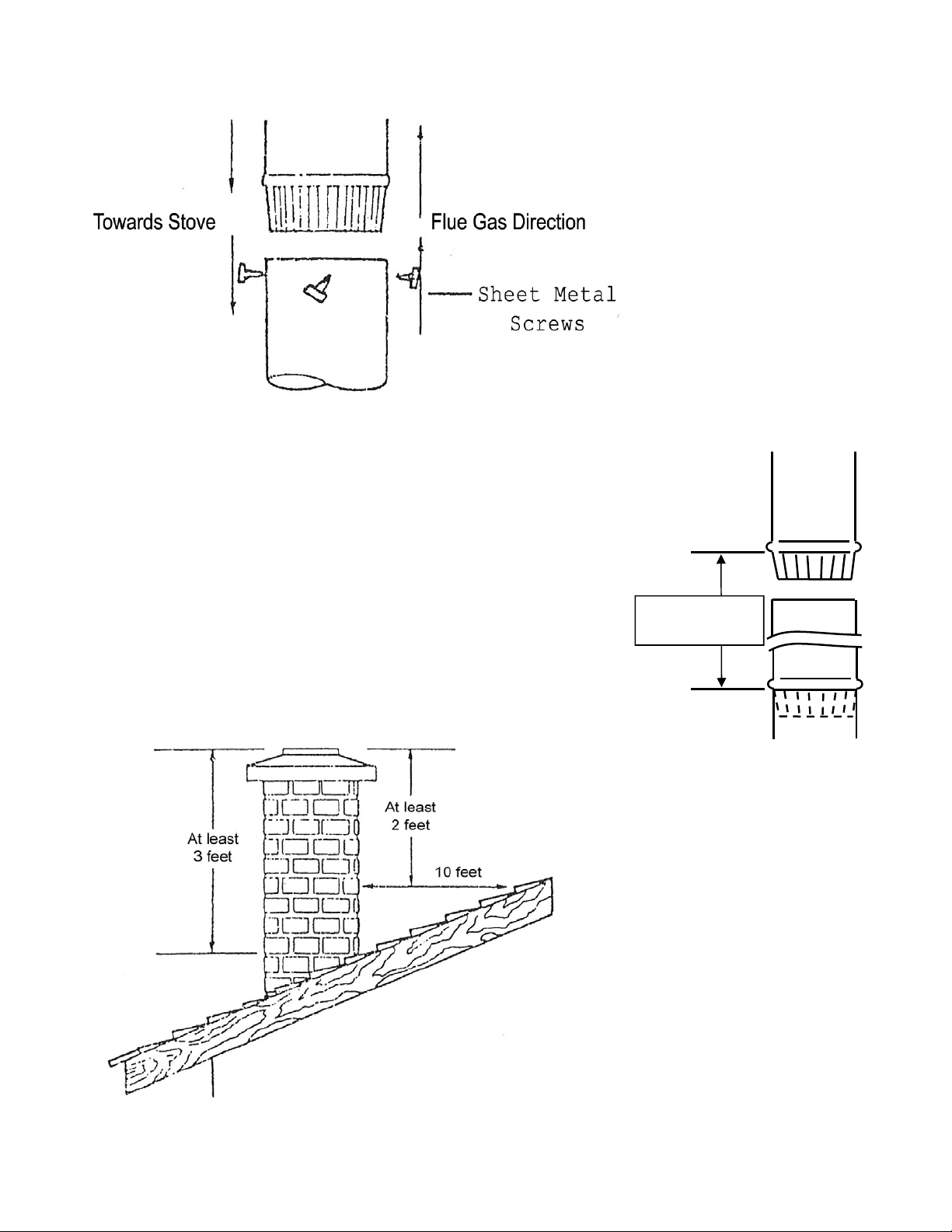
CHIMNEY CONNECTION
Figure 1
CHIMNEY HEIGHT
MEASUREMENT
POINTS
Figure 2
Figure 3
Page 6

THIMBLE
Prefabricated “Listed 2100° UL 103 HT Type Chimney” metal thimbles can be purchased for use
(See Page 19 and 21). Installation instructions from the manufacturer must be strictly followed to
ensure the safety of the system. Clearances to combustible materials must be maintained. Confirm
local building codes for restrictions when connecting stove to masonry thimble through a
combustible wall.
CONNECTION TO A METAL PREFABRICATED CHIMNEY
When a metal prefabricated chimney is used, follow the pipe manufacturer's installation instruction
exactly. Do not mix different pipe. Purchase (from the same manufacturer) and install:
1. ceiling support package
2. wall pass through
3. "T" section package
4. firestops (when needed)
5. insulation shield
6. roof flashing
7. chimney cap
Two methods of chimney installation:
1. Rear exit through wall, exterior chimney outside residence. (See figure 4, Page 8).
2. Rear exit to vertical ceiling exit. (See figure 5, Page 8).
Components illustrated may not look like system you choose, but this demonstrates basic
components needed for a proper and safe installation.
See figure 3 (Page 6) for chimney height. Refer to page 5, "Masonry Chimney" for dimensions.
NOTE: Follow the manufacturer's installation instructions and maintain
specified clearance requirements.
DO NOT CONNECT THIS UNIT TO A CHIMNEY
These parts must be listed to 2100 degree UL 103 HT.
FLUE SERVING ANOTHER APPLIANCE.
Page 7
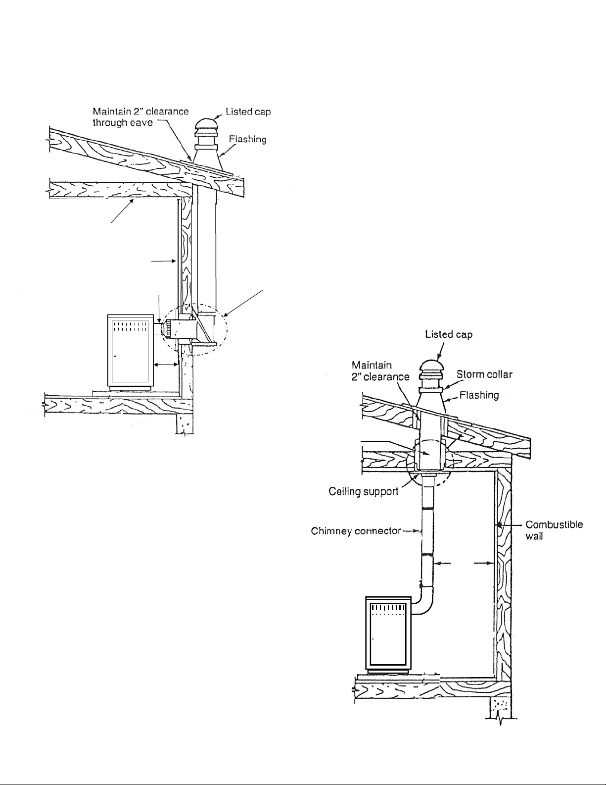
METHODS OF INSTALLATION
Using Listed 2100º UL 103 HT TYPE Chimney Systems
Combustible ceiling
Combustible wall
Chimney connector
Figure 4
LISTED 2100° UL 103 HT TYPE
CHIMNEY T-BOX ASSEMBLY
AND CHIMNEY REFER TO
MANUFACTURERS
INSTALLATION INSTRUCTIONS
LISTED 2100° UL 103 HT TYPE
CHIMNEY ASSEMBLY REFER
TO MANUFACTURERS
INSTALLATION INSTRUCTIONS
Page 8
22”
Figure 5
PREPARING THE ROOM HEATER LOCATION
1. Select an installation location that will give the best airflow from the front of the heater to the
remainder of the home.
2. Place the protective floor pad in position.
3. Place the unit on the pad making sure the minimum clearance specifications are met.
4. If connecting to an existing masonry flue, first ensure that the flue conforms to the
NFPA-211 Code and/or consult your local code for proper procedures.
This model is designed for connection to: any Listed 2100° UL 103 HT. TYPE chimney also any
Listed UL DVL Close Clearance Pipe. Follow pipe manufactures instructions carefully.
CHIMNEY
This room heater must be converted to (1) a chimney complying with the requirements for Type HT
chimneys in the Standard for Chimneys, Factory-Built, Residential, Type and Building Heating
Appliance, UL 103, or (2) a code approved masonry chimney with a flue liner.
CAUTION: Certain installation types require the use of certain chimney types. Please
follow these instructions exactly.
Page 9
 Loading...