

New Buck Corporation Heater Model 80, Buck Stove 80 Installation And Operation Manual
BUCK STOVE
“MEETS PHASE II EPA STANDARDS”
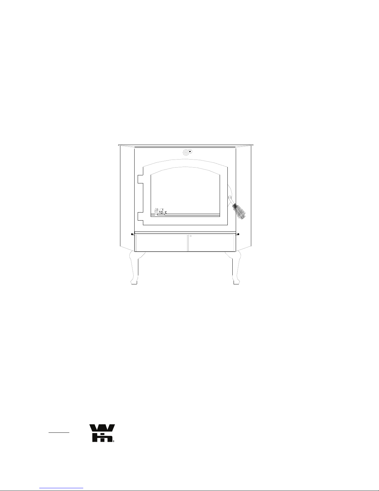
MODEL 80 HEATER
FEATURES
PREPARATION INSTALLATION
OPERATION MAINTENANCE SAFETY
SAFETY NOTICE
If this heater is not properly installed, a house fire may result. For your safety, follow the installation directions.
Contact local building or fire officials about restrictions and installation requirements in your area.
Manufactured by New Buck Corp.—Spruce Pine, NC 28777— Revised 2/03
PN-PI-8000660
Tested by ITS


TABLE OF CONTENTS
1
SECTION I
Room Heater Features ...................................................................................................3
Important Statements.....................................................................................................5-6
SECTION II
Masonry Insert Installation ............................................................................................7-10
SECTION III
Residential Freestanding Heater Installation .............................................................. 11-17
SECTION IV
Wood Heater Safety.....................................................................................................18
SECTION V
Operation .....................................................................................................................19-20
SECTION VI
Preventive Maintenance/Parts Replacement ...............................................................21-22
SECTION VII
Troubleshooting...........................................................................................................23-24
WARRANTY .............................................................................................................25

2

SECTION I
3
The New Buck Corporation room heater Model 80 is one of the safest and most efficient heating systems
available when installed and operated as specified in these instructions and as stipulated on the operation and
installation labels affixed to the unit. The unit is designed to burn wood fuel only.
Please read this entire manual before you install and use your new room heater. Failure to follow instructions
may result in property damage, bodily injury, or even death.
Throughout the manual, you will see this symbol. This indicates areas of importance regarding safety.
Please make a special note of these areas.
Install and use only in accordance with the manufacturer’s installation and operating instructions. Do not
connect this unit to a chimney flue serving another appliance. This unit is not designed for installation into a
Mobile Home.
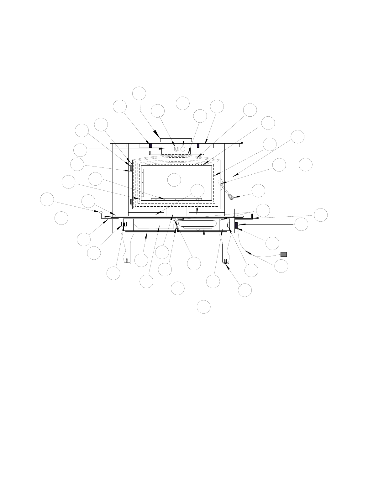
ROOM HEATER FEATURES
Before attempting to install or operate your heater, it is a good idea to familiarize yourself with the features and
operating controls of the unit.
WARNING: Model 80 heater was not designed for fire grates.
1. Bypass Damper: The bypass damper control is located in the top center of the heater front just under the
top. It is operated by pushing or pulling the rod. The damper is fully open when the handle is pulled out
and fully closed when it is pushed in. The damper must be open before the door is opened.
2. Blower Control: The blower control (Rheostat) is located on the side of the unit. This switch controls
the variable speed blower. For blower to operate turn switch from “OFF” position to either “LOW”,
“MEDIUM” or “HIGH”. When stove temperature reaches 110
3. Primary Air Controls:
hearth. They are operated by moving in and out to control the amount of primary air entering the firebox.
4. Warm Air Outlets: Provides heat extraction from the top of the firebox.
5. Baffles: Directs air flow around the unit for maximum heat transfer.
6. Air Inlet: Allows cool air near the floor to be circulated through the blower and back into the warm air
chamber of the heater.
7. Stand: Elevates heater above the floor for safety and a neat appearance.
8. Door: Provides an “airtight” feature. The door allows a much higher burning efficiency than can be
obtained with an open firebox.
9. Hearth Extension: Offers protection from spilled ashes and cinders.
10. Power Cord: Provides electrical power to operate the blower.
11. Chimney Connector: Used to connect unit to chimney or direct connect kit.
12. Catalysts: Enables the unit to burn cleanly and efficiently.
13. Temperature Monitor: The location can be used for either a fireplace insert or freestanding installation.
Monitor hole is located to the right of the damper rod on the front. Remove plug and insert probe provided
by manufacturer.
14. Cover Door: Conceals blower, blower controls and ash pan.
15. Airway: Primary air is directed in such a way as to provide a “sweeping” air wash over the glass to assist
in keeping it clean.
16. Ash Pan: Provides for easy ash removal.
The primary air intake draft controls are located at the left and right side of the
o
blower will automatically come on.
14
4
10
13
Model 80
Wood Stove
40
5
1
11
21
4
20
32
15
7
39
33
15
18
Buck
Stove
8
19
3A
35
6
36
29
1. By Pass Damper & Brass Spring Handle
2. Blower Control (Rheostat)
3. Primary Air Control (Right Side)
3a. Primary Air Control (Left Side)
4. Warm Air Outlets
5. Baffles (Interior of Stove)
6. Air Inlet
7. Door
8. Hearth Extension
9. Power Cord
10. Catalyst (interior firebox)
11. Catalyst Probe
12. Automatic / Off / Man. Switch
13. Brass Cap
14. Hinge Block
15. Air Control Brass Knobs
16. Shot Gun Air Control
17. Door Glass
18. Glass Clips
19. Hearth Brass
20. Door Gasket
28
34
17
25
23
16
7
3
&
31
27
2
30
9
26
22
24
21. Lower Heat Shield
22. Leveling Screws
23. Bottom Firebrick
24. Motor
25. Motor Mount Bracket
26. Cover Door
27. Cover Door Screws
28. Shot Gun Air Box
29. Ash Pan
30. Disc Thermostat
31. Door Handle & Brass Spring Handle
32. Air Wash Screen
33. Glass Gasket
34. Cover Door Hinge
35. Magnet Holder
36. Cover Door Magnet
37. Door Latch
38. Door Latch Screw
39. Hinge Pins
40. 8" Flue Exit
12
3
8
3

5
EPA COMPLIANCE STATUS
This manual describes the installation and operation of the New Buck Corporation, Model 80 wood heater. These
heaters meet the U.S. Environmental Protection Agency’s Emission limits for wood heaters sold after July 1, 1992.
Under specific test conditions this heater has been shown to deliver heat at rates ranging from approximately 9,000
to 40,300 BTU/hr for the Model 80.
CATALYST EQUIPPED
This wood heater contains a catalytic combustor, which needs periodic inspection and replacement for proper
operation. It is against the law to operate this wood heater in a manner inconsistent with operating instructions in
this manual or if the catalytic element is deactivated or removed.
CATALYST WARRANTY
The combustor supplied with this heater is a 3 cell catalyst with an overall dimension of 2" x 6" x 7". Consult the
catalytic combustor warranty also supplied with this heater. All warranty claims should be addressed to:
Applied Ceramics
Customer Service Department
P.O. Box 29664
Atlanta, GA 30359
770-448-6888
See enclosed catalyst warranty for instructions. New Buck Corporation does not handle catalyst replacements.
Customer can order direct form Applied Ceramics.
PROPER FUEL SELECTION
This heater is designed to burn natural wood only. Higher efficiencies and lower emissions generally result when
burning air dried seasoned hardwoods, as compared to softwoods or to green or freshly cut hardwoods.
DO NOT BURN:
Treated Wood Garbage Solvents Trash
Coal Cardboard Colored Paper
Burning treated wood, garbage, solvents, colored paper or trash may result in release of toxic fumes and may
poison or render the catalytic combustor ineffective.
Burning coal, cardboard, or loose paper can produce soot, or large flakes of char or fly ash that can coat the
combustor, causing smoke spillage into the room and rendering the combustor ineffective.
ACHIEVING CATALYTIC LIGHT-OFF
The temperature in the stove and the gases entering the combustor must be raised to between 500
catalytic activity to be initiated. This can be determined with the use of a temperature monitor (TM-20). During the
start up of a cold stove a medium to high firing rate must be maintained for about 20 minutes. This ensures that the
stove, catalyst, and fuel are all stabilized at proper operating temperatures. Even though it is possible to have gas
temperatures reach 600
immediately it may go out or the combustor may stop working. If this happens open the damper to raise the
temperature to activate the catalyst. Once the combustor starts working, heat generated in it by burning the smoke
will keep it working.
o
F within two to three minutes after a fire is started, if the fire is allowed to die down
o
F to 700o F for

6
ACHIEVING CATALYTIC LIGHT-OFF WHEN REFUELING
During the refueling and rekindling of a cool fire, or a fire that has burned down to the charcoal phase, operate the
stove at a medium to high firing rate for about 15 minutes to ensure that the catalyst reaches approximately 600
o
F.
CATALYST MONITORING
It is important to periodically monitor the operation of the catalytic combustor to ensure that it is functioning
properly, and to determine when it needs to be replaced. A non-functioning combustor will result in a loss of
heating efficiency, and an increase in creosote and emissions.
This catalytic heater is equipped with the means to install a temperature probe to monitor catalyst operation.
Properly functioning combustors typically maintain temperatures in excess of 1000
not in excess of 500
o
F refer to Catalyst Troubleshooting Section of this owner’s manual.
o
F. If catalyst temperatures are
CAUTION AGAINST OVER-FIRING
Do Not Over-fire This Heater.
Attempts to achieve heat output rates that exceed heater design specifications can result in permanent damage to the
heater and to the catalytic combustor.
ASH REMOVAL
Whenever ashes build up in the firebox and when the fire has burned down and cooled, remove excess ashes.
Leave an ash bed approximately 1 inch deep on the firebox bottom to help maintain a hot charcoal bed.
Ashes should be placed in a metal container with a tight fitting lid. The closed container of ashes should be placed
on a non-combustible floor or on the ground, away from all combustible materials, pending final disposal. The
ashes should be retained in the closed container until all cinders have thoroughly cooled.
SECTION II
7
MASONRY INSERT INSTALLATION
INSTALLATION PRECAUTIONS
It is not necessary to direct connect this unit, but testing has shown that it is necessary for best performance in a
poorly drawing flue, oversized flue liner or a short chimney.
Use the following to complete the installation of the unit as an insert:
Kit # PA FP80
Note: Clearances to mantel may be reduced by using a tested or listed mantel shield.
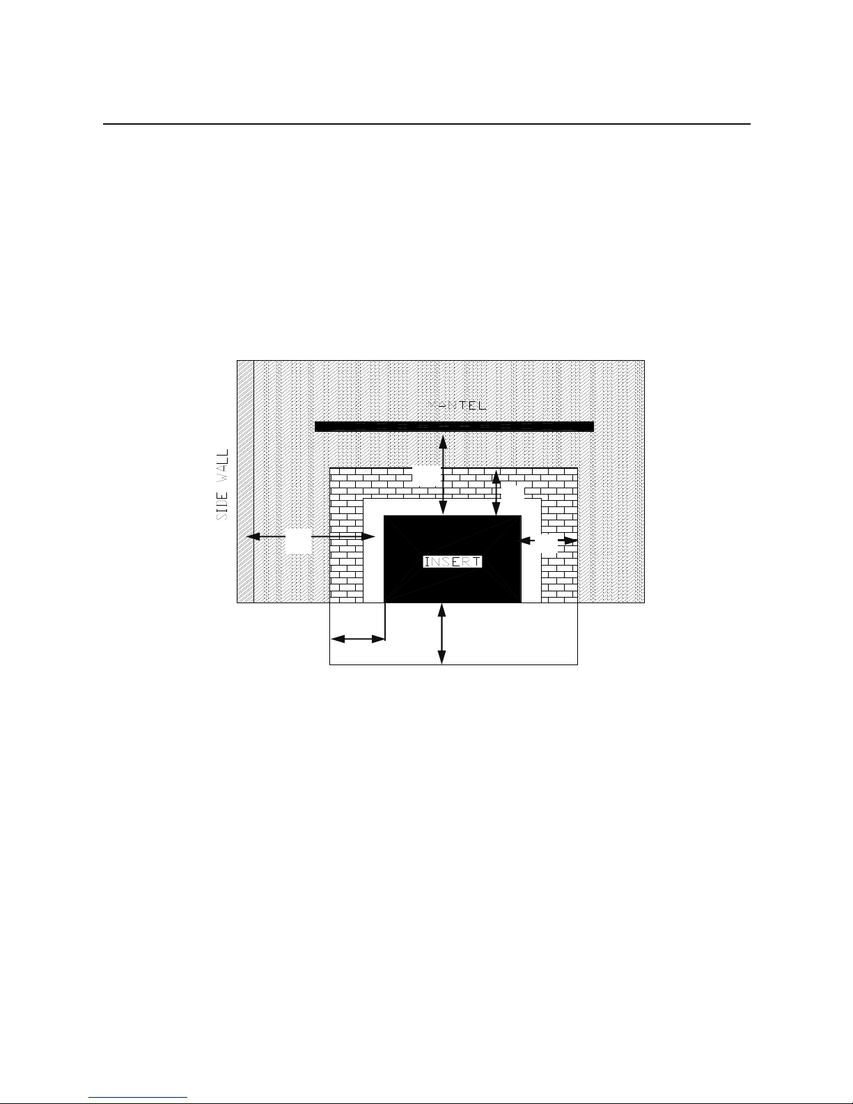
INSTALLATIONS (Fireplace Insert)
Minimum Clearances to Combustible Materials (in inches):
12"
8"
24"
9"
9"
16"
HEARTH EXTENSION
FIGURE 1
FIREPLACE INSERT
MINIMUM CLEARANCES:
The Model 80 Fireplace Insert is intended for installation in accordance with the standard for chimneys, fireplaces,
vents, and solid-fuel burning appliances. NFPA-211 Code: NOTE: This model is not intended for installation into
zero clearance or pre-fabricated fireplace.
1. The hearth must be of masonry construction and must extend a minimum of 16" in front of the firebox opening
and a minimum of 8" to either side of the firebox opening.
2. Floor protector must be 3/8" minimum thickness non-combustible material or equivalent.
3. If your fireplace has wood trim above it, the wood trim must be at least 9" above the top of the unit.
4. If your fireplace has a wood mantel, the mantel or mantel supports must be located at a height of 24" above the
top of the unit.
REQUIRED FIREPLACE DIMENSIONS
Minimum and/or maximum fireplace dimensions:
Height Width
Min. Max. Min. Max.
Model 80 23 1/2" 32 1/2" 29" 46"
 Loading...