

New Buck Corporation Buck Stove 42ZC, Buck Stove 42WS Instruction Manual
MODEL 42
MAY BE INSTALLED AS A ZERO CLEARANCE FIREPLACE
OR WITH AN OPTIONAL WOODEN SURROUND
VENT-FREE
WARNING: If the information in this manual is not followed exactly, a fire or
explosion may result causing property damage, personal injury or loss of life.
− Do not store or use gasoline or other flammable vapors and liquids in the vicinity of this
or any other appliance.
WHAT TO DO IF YOU SMELL GAS
• Do not try to light any appliance.
• Do not touch any electrical switch; do not use any phone in your building.
• Immediately call your gas supplier from a neighbor’s phone. Follow the gas supplier’s
instructions.
• If you cannot reach your gas supplier, call the fire department.
− Installation and service must be performed by a qualified installer, service agency or the
gas supplier.
This is an unvented gas-fired heater. It uses air (oxygen) from the room in which it is installed. Provisions for adequate combustion and ventilation air must be provided. Refer to
section “ Producing Adequate Ventilation” page 13.
This appliance may be installed in an aftermarket, permanently located, manufactured
(mobile) home, where not prohibited by local codes.
This appliance is only for use with the type of gas indicated on the rating plate. This appliance is not convertible for use with other gases.
INSTALLER: Leave this manual with the appliance.
CONSUMER: Retain this manual for future reference.
Manufacturer: NEW BUCK CORPORATION
P.O. Box 69
8000 Highway 226 South
Spruce Pine, NC 28777
This appliance is intended for supplemental
heating.
Revised December 2006


TABLE OF CONTENTS
Page 1
Safety Information and Warnings ....................................................................................... 3
Installation (ZC) or (WS) .................................................................................................... 6
Fireplace and Framing Dimensions (ZC) ............................................................................ 7
Fireplace Clearances(ZC) .................................................................................................... 8
Finishing Your Fireplace(ZC) ............................................................................................. 9
Mantel Profiles For Zero Clearance(ZC) .......................................................................... 10
Optional Wooden Surround (WS)…...…………………………………………………...11
Producing Adequate Ventilation ...................................................................................... .13
Ventilation Air Indoors ..................................................................................................... 15
Ventilation Air Outdoors ................................................................................................... 16
Gas Connection ................................................................................................................. 17
Gas Pressure Check ........................................................................................................... 18
Placement of Logs DX 2733 Logs…………………………………………………...18-19
Placement of Logs E.S.B. Logs………………………………………………………….20
Placement of Logs CR3329 Logs……………..……………………………………… 21
Lighting Instructions - Millivolt (ITT) .............................................................................. 22
Lighting Instructions - Modulating (SIT) or –Manual (SIT)…………………………….26
Lighting Instructions - Millivolt (SIT) .............................................................................. 30
Flame Check ...................................................................................................................... 34
Wiring Diagram ........................................................................................................... 35-36
Important Safeguards ........................................................................................................ 37
Trouble Shooting .......................................................................................................... 38-40
Service/Replacement Parts ........................................................................................... 42-48
Warranty/Owner Registration ........................................................................................... 49

Page 2
SECTION I
Page 3
SAFETY INFORMATION WARNINGS
IMPORTANT: READ THIS OWNER’S MANUAL CAREFULLY AND COMPLETELY
BEFORE TRYING TO ASSEMBLE, OPERATE, OR SERVICE THE APPLIANCE.
IMPROPER USE OF THESE LOGS CAN CAUSE SERIOUS INJURY OR DEATH FROM
BURNS, FIRE, EXPLOSION, AND CARBON MONOXIDE POISONING.
Early signs of carbon monoxide poisoning resemble the flu, with headaches, dizziness, and/or
nausea. If you have these signs, the heater may not be working properly. Get fresh air at once!
Have heater serviced.
Some people-pregnant women, persons with heart or lung disease, anemia, those under the
influence of alcohol, and those at high altitudes-are more affected by carbon monoxide than
others.
CAUTION: Strong drafts, such as a ceiling fan placed directly in front of the heater
(pulling from either direction) may create sooting. Sooting will discolor
walls.
1. The installation must conform with local codes ,or in the absence of local codes, with the
National Fuel Gas Code, ANSI Z223.1/NFPA54.
2. This appliance may be installed in an After-Market* Manufactured (Mobile) Home,
where not prohibited by state or local codes.
* (After-Market: Completion of sale, not for purpose of resale from the manufacturer.)
This appliance is only for use with the type of gas indicated on the rating plate. This
appliance is not convertible for use with other gases.
NOTE: See Section VII, “Producing Adequate Ventilation” page 13.
IMPORTANT: VENT-FREE HEATERS ADD MOISTURE TO THE AIR. ALTHOUGH THIS
IS BENEFICIAL, INSTALLING HEATER IN ROOMS WITHOUT ADEQUATE
VENTILATION MAY CAUSE MILDEW TO FORM FROM TOO MUCH MOISTURE.
3. Never install this heater:
♦ in a recreational vehicle, bathroom, bedroom, or any other sleeping quarters
♦ where curtains, furniture, clothing, or other flammable objects are less than 42" from the
front of the heater
♦ in high traffic areas or in windy areas
4. Two models are available. One specific model for propane (LP), and one for natural gas.
Use the correct type gas for your home. Do not convert from one gas type to another.
“WARNING:
DANGEROUS.”
ANY CHANGE TO THIS HEATER OR ITS CONTROLS CAN BE

5. If this heater is used with propane gas, do not place propane supply tank (s) inside any structure.
Page 4
6. What To Do IF You Smell Gas:
Shut off gas supply.
- Do not try to light any appliance.
- Do not touch any electrical switch; do not use any phone in your building.
- Immediately call your gas supplier from a neighbor’s phone.
Follow the gas supplier’s instructions.
- If you cannot reach your gas supplier, call the fire department.
7. When operated for the first time, the logs may emit a “paper burning” smell. This smell will
gradually diminish and will be totally eliminated after the first few hours of operation. Run the gas
logs with the flue damper open during this time. Do not use blower at this time.
8. “This heater shall not be installed in a confined space or unusually tight construction unless
provisions are provided for adequate combustion and ventilation air.” See “Producing
Adequate Ventilation”, page 11.
9. Surface of gas logs becomes very hot when operating. Keep children and adults away from hot
surface. Gas logs will remain hot for sometime after shutdown. Allow surface to cool before
touching.
10. Do not place clothing or other flammable material on or near the appliance.
11. If equipped, fresh air damper must be closed.
12. Keep appliance area clean and free from combustible materials, gasoline, and other flammable
flammable vapors and liquids. .
13. If burner shuts off, do not relight until you provide fresh outside air. If burner continues to shut off,
have unit serviced.
14. Do not use this heater if any part has been under water. Immediately call qualified service
technician to inspect the room heater and to replace any part of the control system and any
gas control which has been under water.
15. Turn off the heater and let cool before servicing.
16. These logs are made of bonded fiber. When removing logs and base, do not damage the bonded
material. If the material is damaged extensively, loose fiber dust could be emitted into the air.
17. Any safety screen or guard removed for servicing an appliance must be replaced prior to
operating the heater.
18. This appliance is intended for supplemental heating.
19. “WARNING: Any change to this heater or its controls can be dangerous.”
20. Installation and repairs should be performed by a qualified service person. The appliance
should be inspected before use and at least annually by a professional service person. More
frequent cleaning may be required due to excessive lint from carpeting, bedding material, etc.
It is imperative that control compartments, burners and circulating air passageways of the
appliance be kept clean.

21. All heater screens must be kept closed when operating the gas logs.
Page 5
”WARNING: Failure to keep the primary air opening(s) of the burner(s) clean may result in
22.
sooting and property damage.”
23. Do not use this heater for burning trash or cooking. Never place matches, paper, garbage, or any
other material on top of logs or into the flames.
24. Do not install or operate this heater in areas where impurities in the air exist (such as tobacco
smoke or heavy cooking grease). Particles from impurities may discolor walls.
25. Due to high temperatures, the appliance should be located out of traffic and away from
furniture and draperies.
26. Children and adults should be alerted to the hazards of high surface temperature and should
stay away to avoid burns or clothing ignition.
27. Young children should be carefully supervised when they are in the same room with the
appliance.
28. An unvented room heater having an input rating of more than 10,000 Btu per hour shall not be
installed in a bedroom or bathroom.
29. The appliance and its appliance main gas valve must be disconnected from the gas supply
piping system during any pressure testing of that system at test pressure in excess of 1/2 psi
(3.5 kPa).
30. The appliance must be isolated from the gas supply pipping system by closing its equipment
shut-off valve during any pressure testing of the gas supply piping system at test pressures
equal to or less than 1/2 psi (3.5 kPa).
31. “
WARNING: Do not allow fans to blow directly into fireplace. Avoid any drafts that alter
burner flame patterns.”
32. “
WARNING: Do not use a blower insert, heat exchanger insert or other accessory not
approved for use with this heater.”
33. Adequate clearances around air openings. Nothing may be placed over any of the air openings
on this appliance, or can any of the air openings be modified in anyway.

INSTALLATION FOR MODEL 42 (ZC or WS)
Page 6
Your New Buck Vent-Free Gas Fireplace Heater may be installed in Residential or *AfterMarket Manufactured Mobile Homes. This appliance may be installed in an *After Market
Manufactured Mobile Home, where not prohibited by state or local codes.
(Exception: This appliance may not be installed in a bedroom or bathroom.)
* (After Market: Completion of sale, not for the purpose of resale from the manufacturer).
This appliance is only for use with the type of gas indicated on the rating plate. This appliance
is not convertible for use with other gases.
NOTE: See page 13 for “Producing Adequate Ventilation”.
CHOOSING THE LOCATION FOR YOUR FIREPLACE: (ZC or WS)
Figure 1 shows some of the many ways your fireplace may be installed. Consider the traffic
pattern in your room and the location of doors and windows. Moving air from ceiling fans,
open doors, and hot air grills may cause the flames to soot. If a disturbance is found that affects
the flames, it must be eliminated by turning off the ceiling fan, closing the door, or closing the
hot air register. A corner location may be best where space is limited.
Your fireplace weighs no more than some of your fine furniture. If the fireplace is located near
a load bearing wall, additional supports to the foundation will not be necessary. HEAVY
FACINGS, SUCH AS BRICK, STONE, ETC., MAY REQUIRE ADDITIONAL
FOUNDATION SUPPORT.
NOTE: If this appliance is installed directly on carpeting, tile or other combustible
material, other than wood flooring, the appliance shall be installed on a metal or wood
panel extending the full width and depth of the appliance.
GAS LINES
The gas supply line and electrical supply
must be installed before framing in the
fireplace by a licensed installer.
DRAFTS
Do not locate the fireplace in high traffic
areas or areas exposed to high drafts and
winds. Locate the fireplace away from
furniture and draperies.
CORNER
Figure 1
PARTIAL ROOM PROJECTION
ROOM DIVIDER
FULL ROOM PROJECTION
FLUSH
18-15/16"
Page 7
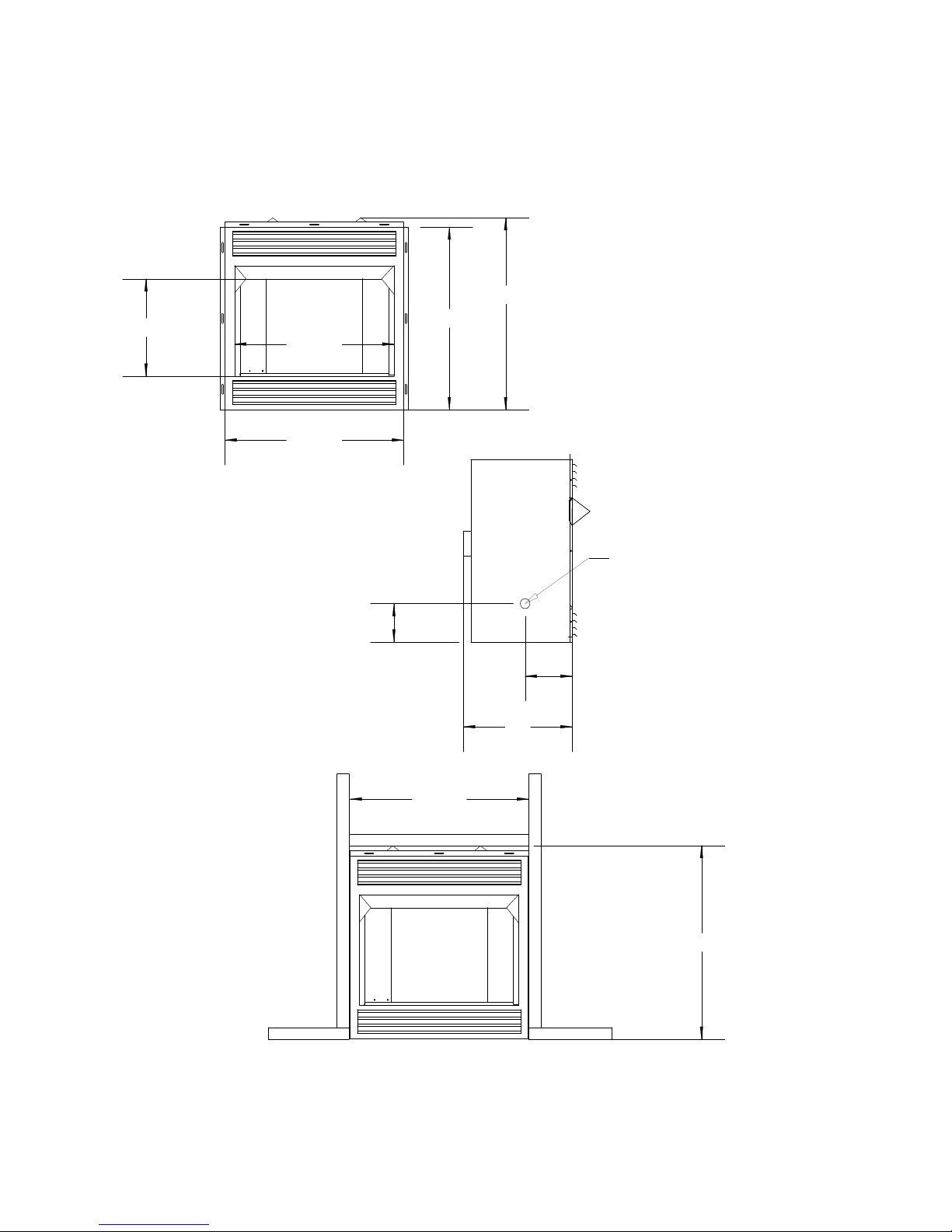
Fireplace and Framing Dimensions For Model 42 (ZC)
Zero Clearance Installation
36-5/8"
35-5/8"
41-1/2"
45-5/8"
Figure 2
GAS LINE
2-5/8"
9"
19"
45-5/8"
36-5/8"
WARNING:Installation and repairs should be performed by a qualified service person. The appliance
should be inspected before use and at least annually by a professional service person. More frequent cleaning may be required due to excessive lint from carpeting, bedding material, etc. It is imperative that control
compartments, burners and circulating air passageways of the appliance be kept clean.
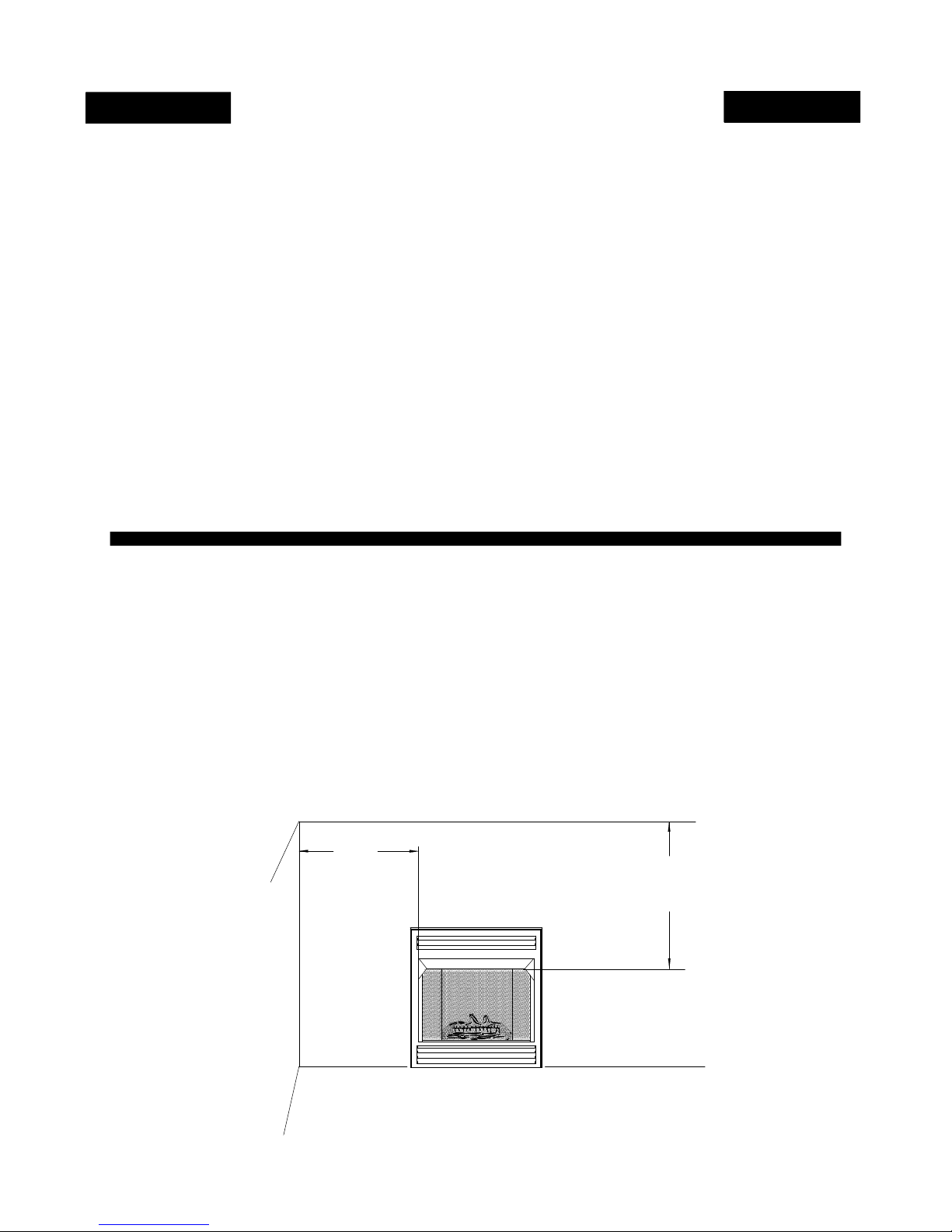
FIREPLACE CLEARANCES (ZC)
Page 8
The fireplace may be placed directly on a combustible
floor, against a combustible wall at marked clearances, or
on a raised wooden platform.
If the fireplace is to be installed on a raised wooden
platform, the platform must be a continuous level surface.
The fireplace must be secured in place so it cannot shift
positions. The nailing flanges on the sides of the firebox
make securing it to the framing easy. They were designed
to allow the installation of 1/2" wallboard or plywood flush
with the face of the fireplace.
Only the header (see Figure 2) may rest on the standoffs
on top of the firebox.
When the firebox is installed over carpeting, vinyl tile, or
INSTALLING THE FIREBOX (ZC)
any combustible material other than wood flooring, it must
be installed on a metal or wood panel extending its full
width and depth. Alternatively, the carpeting, vinyl tile, etc.
may be removed beneath the fireplace before installing.
COMBUSTIBLE MATERIALS MUST NOT BE INSTALLED
OVER OR TOUCH ANY BLACK PAINTED SURFACE. DO
NOT BLOCK HEAT CIRCULATING AIR OUTLETS. DOING
SO MAY RESULT IN POTENTIAL FIRE HAZARDS
.
1. Sidewall Clearances: Clearances from the side of the
fireplace opening to any adjacent combustible wall should
not be less than 7"right side and 7” left side, facing the
frontof the appliance.
2. Ceiling Clearances: The ceiling height should
not be less than 42" from the top of the fireplace
opening.
This list of specific instructions will help you make certain that every
installation operation is performed correctly. Complete the installation
steps in the sequence shown.
LOCAL BUILDING CODES SHOULD BE CONSULTED IN ALL CASES AS
TO THE PARTICULAR REQUIREMENTS CONCERNING THE
INSTALLATION OF FACTORY BUILT FIREPLACES.
Select the location
for the fireplace by taking into consideration the factors previously
outlined in the section called “Choosing the Location.” See page 6.
Framing the Firebox
The width of the framed opening must be 45 5/8". The height of the
framed opening must be 35 11/16". The entire fireplace can be
elevated above the floor to achieve a raised hearth effect. This can be
done by adding a small platform to achieve the desired height.
NOTE: The wiring for the lower blower must be installed during the
framing stage. The nailing flanges on both sides were designed to allow
the installation of 1/2" wallboard or plywood flush with the face of the
fireplace.
When the framing is inside, the outside wall will be insulated. If the
framing or chase is outside, thin insulation should be used in the
framing on the back, sides, and top. The bottom should be insulated
with a hard insulating board. This will prevent cold from going into the
chase through the fireplace to the living space.
Install the Firebox
Install the firebox into the framed opening by placing it directly in front
of the opening and sliding it into the proper position.
Level the Firebox
Check the level of the firebox on the top edge of the fireplace face.
Shim if necessary.
Secure the Firebox
Secure the fireplace to the framing. The nailing flanges on the firebox
will make securing the firebox to the frame quick and easy. Use
appropriate size nails or screws to secure the firebox.
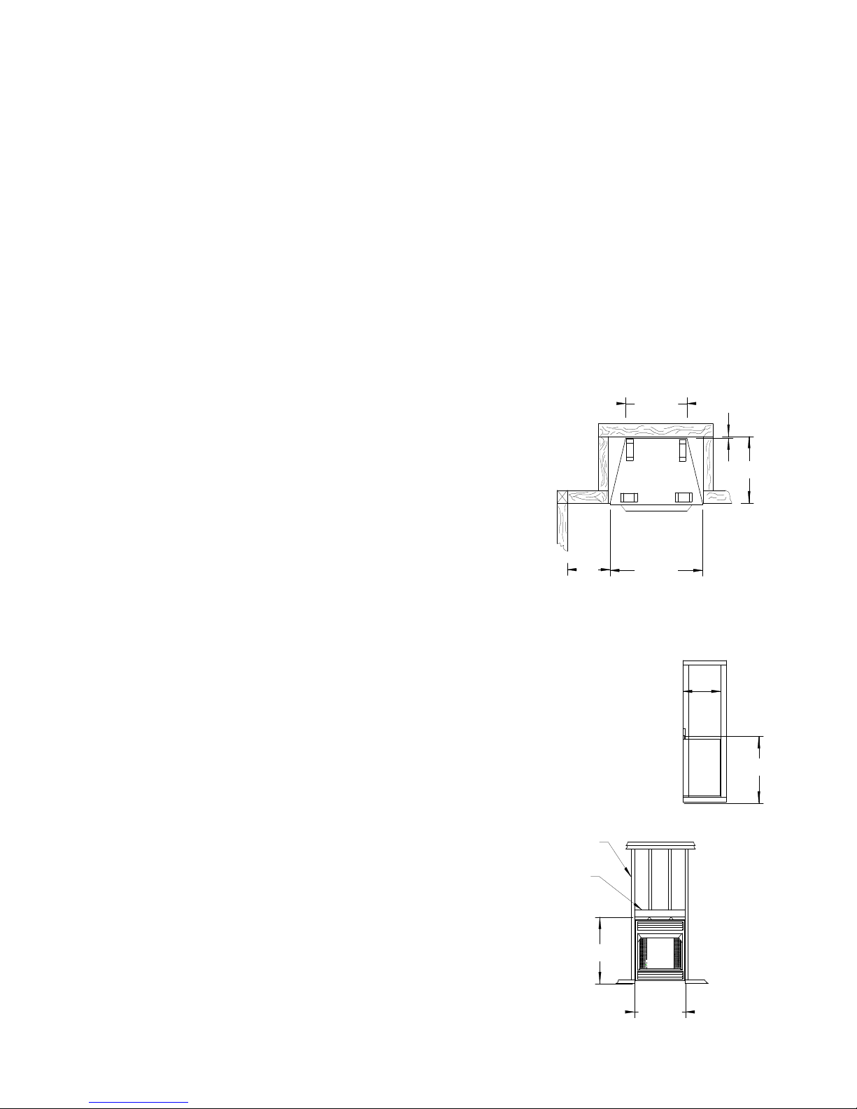
31-1/2"
Figure 3
7" *
* Note: Minimum 1/2" clearance
NOT required at this point
FRAMING
HEADER
36-5/8"
TOP
VIEW
45-5/8"
21 1/2"
FRONT
VIEW
45-5/8"
1/2"
18-1/2"
SIDE
VIEW
36-5/8"
FINISHING YOUR FIREPLACE (ZC)
Page 9
There is a wide variety of finishing material
available for your fireplace from formal wall
treatments with marble and mantels, to rustic
wood paneling, stone or brick. Noncombustible materials used in this installation
such as slate, tile, marble, etc. must be at least
1/2" thick.
IT IS IMPORTANT THAT THE BLACK FACE OF
THE FIREPLACE NOT BE COVERED WITH ANY
TYPE OF COMBUSTIBLE MATERIAL.
Non-combustible facing materials such as
marble, brick, or ceramic tile may overlap the
black face of the fireplace up to the opening on
either side of the fireplace. Seal all joints
between the black fireplace face and the wall
covering with a heat-resistant material such as
rock wool insulation or mortar. Be sure to use
high temperature adhesive or mortar when
CLEARANCES (ZC)
To ensure a safe installation, the following
must be carefully observed.
1. Sidewall Clearances: Clearances from the
side of the fireplace opening to any adjacent
combustible wall should not be less than
7"right side and 7” left side, facing the front of
the appliance. See Figure 4.
2. Ceiling Clearances: The ceiling height
should not be less than 42" from the top of the
anchoring brick, stone, or tile to the face of the
fireplace. Check to see whether man-made
brick and stone are made of non combustible
materials before using them on the face of the
fireplace. Some of these products contain
combustible materials. Combustible wall
coverings such as paneling or wallboard may
not overlap the black face of the fireplace. The
space between the wall covering and the
fireplace should be sealed with a heat resistant
material such as rock wool insulation or mortar.
NOTE: An “L” shaped steel lintel must be
installed across the top of the firebox opening
where facing materials such as brick or stone is
used on the face of the firebox. It acts as a
support/firestop. It should be attached to the
face of the fireplace with screws and sealed to
the fireplace with a heat-resistant sealer.
fireplace opening.
3. Mantel Clearances: We have provided 3
different situations to position your mantel.
See Figure 5.
Non-combustible materials used in this
installation such as slate, tile, marble, etc. must
be at least 1/2" thick.
4. Floor Clearances: No clearance is required
if the appliance is installed per these
instructions.
SIDE WALL
7" MIN.
FIGURE 4
CLEARANCE
FROM FIREPLACE
OPENING TO SIDE WALL
42" MIN.
CLEARANCE
TO CEILING
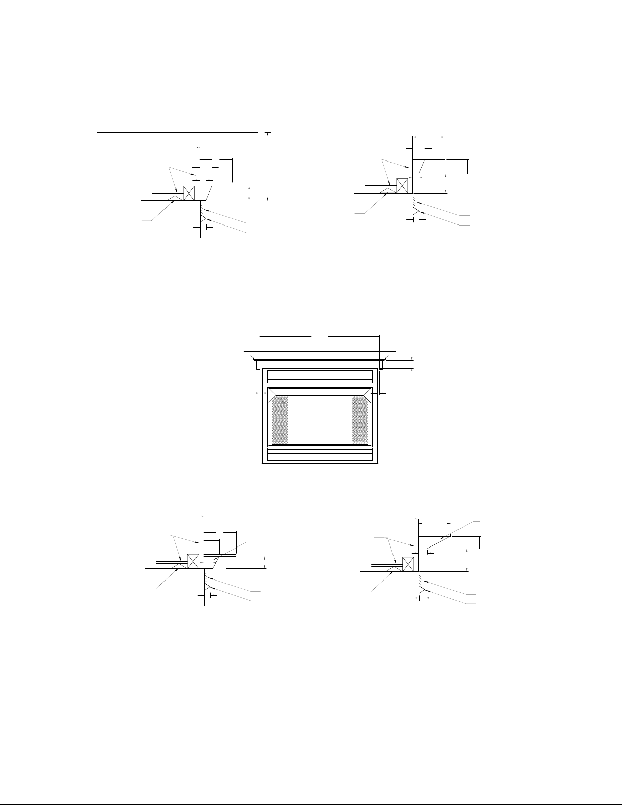
MANTEL PROFILES FOR ZERO CLEARANCE (ZC) CABINET
Page 10
MUST BE FOLLOWED
Figure 5
COMBUSTIBLE
MATERIAL
STAND OFF
42-ZC-FP
2"
Bottom of 3/4" Base or Support
must be Flush with top of Unit
if mantel is 10" wide or less.
10"
3/4"
CEILING
3-1/2"
MANTELS WITH 3/4" BASE
42"
3"
LOUVERS
HOOD
FRONT VIEW OF MODEL 42-ZC-FP
FLAT MANTEL WITH SUPPORTS
50-3/8"
2-3/8"
COMBUSTIBLE
MATERIAL
STAND OFF
42-ZC-FP
2"
Bottom of 3/4" Base or Support
must be at least 2-1/2" from top
of Unit if mantel is 10" wide or more.
3"
2-3/8"
12"
3-1/2"
3/4"
3"
2-1/2"
LOUVERS
HOOD
COMBUSTIBLE
MATERIAL
STAND OFF
42-ZC-FP
2"
Bottom of 2-1/2" Base or Support
must be Flush with top of Unit
if mantel is 12" wide or less.
MANTELS WITH 2-1/2" BASE
12"
6"
2-1/2"
SUPPORT
3"
LOUVERS
HOOD
COMBUSTIBLE
MATERIAL
STAND OFF
42-ZC-FP
12"
2-1/2"
2"
SUPPORT
3"
2-1/2"
LOUVERS
HOOD
Bottom of 2-1/2" Base or
Support must be at least
2-1/2" from top of Unit if
mantel is 12" wide or more.
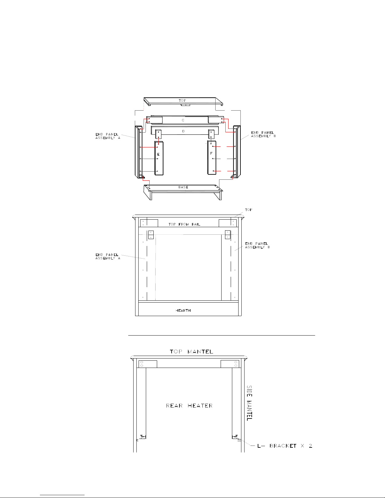
INSTALLATION OF MODEL 42 (WS)
Page 11
WITH OPTIONAL WOODEN SURROUND (KIT#PAKDM42)
1. When choosing the right location for your heater and wooden surround (mantel) keep the
following in mind:
NOTE: Due to high temperatures, this heater should be located out of traffic areas and
away from furniture and draperies.
NOTE: Kit No. (PA KDM42) Optional Wooden Surround (Mantel) for Model 42 (WS).
CAUTION: THE INSTALLATION MUST CONFORM WITH LOCAL CODES OR,
IN THE ABSENCE OF LOCAL CODES, WITH THE NATIONAL FUEL GAS
CODES, ANSI Z223.1/NFPA 54.
NOTE: See page 17 for “Gas Connection” and page 18 for “Gas Pressure Check”.
WARNING: YOUNG CHILDREN SHOULD BE CAREFULLY SUPERVISED WHEN
THEY ARE IN THE SAME ROOM WITH THE APPLIANCE.
DO NOT PLACE CLOTHING OR OTHER FLAMMABLE MATERIAL ON OR NEAR
THE APPLIANCE
2. Screen(s) can not be removed or altered (Position screen(s) in the closed position before
leaving heater unattended).
3. Follow instructions for assembly of (Optional) Wooden Surround (Mantel). See
instructions supplied with surround.
4. After mantel has been assembled, slide the heater from the rear into the opening of the
surround.
NOTE: Place a cloth or blanket over the front portions of the mantel as not to mar the wood.
5. Center the heater in the opening of the surround (mantel).
6. Fasten mantel to hearth by using 1/2" wood screws.
7. Insert the nine (9) wood screws provided with wooden surround through slots on nailing
flange and secure in place.
8. Position mantel and fireplace into desired location.
NOTE: Hook gas supply line into heater. Check for leaks using soap and water, not an
open flame.
NOTE: At this point, you may want to anchor the surround to the wall or floor.
9. Now you are ready to position the log set. See pages 18, 19, 20.
Page 12
10. To light the heater, see “Lighting Instructions”, pages 21 through 32. Make sure you have the
right gas valve for Natural or LP gas.
AS VIEWED FROM BACK OF SURROUND
WOODEN SURROUND (MANTEL) BASE

PRODUCING ADEQUATE
Page 13
VENTILATION
This section is for residential or manufactured (mobile) installation
“This heater shall not be installed in a confined space or unusually tight construction unless
provisions are adequate combustion and ventilation air.”
The National Fuel Gas Code, ANSI Z223.1/NFPA 54 defines a confined space as a space
whose volume is less than 50 cubic feet per 1,000 BTU per hour (4.8m 3 per kw) of the
aggregate input rating of all appliances installed in that space and an unconfined space as a
3
space whose volume is not less than 50 cubic feet per 1,000 BTU per hour (4.8m
per kw) of
the aggregate input rating of all appliances installed in that space. Rooms communicating
directly with the space in which the appliances are installed, through openings not furnished
with doors, are considered a part of the unconfined space.
“WARNING: IF THE AREA IN WHICH THE HEATER MAY BE OPERATED IS
SMALLER THAN THAT DEFINED AS AN UNCONFINED SPACE OR IF THE
BUILDING IS OF UNUSUALLY TIGHT CONSTRUCTION, PROVIDE
ADEQUATE COMBUSTION AND VENTILATION AIR BY ONE OF THE
METHODS DESCRIBED IN THE NATIONAL FUEL GAS CODE, ANSI Z223.1/
NFPA 54, SECTION 5.3 OR APPLICABLE LOCAL CODES.”
Unusually tight construction is defined as construction where:
a) Walls and ceilings exposed to the outside atmosphere have a continuous water vapor
retarder with a rating of 1 perm (6 x 10
-11
kg per pa-sec-m2) or less with openings gasketed or
sealed;
b) Weather stripping has been added on openable windows and doors, and
c) Caulking or sealants are applied to areas such as joints around window and door frames,
between sole plates and floors, between wall-ceiling joints, between wall panels, at
penetrations for plumbing, electrical, and gas lines, and at other openings.
NOTE: SOME AREAS IN THE UNITED STATES HAVE HIGHER REQUIREMENTS
FOR CUBIC FEET PER 1000 BTU/ HOUR INPUT. (EX. CINCINNATI, OHIO CODES
REQUIRE 70 CUBIC FEET). CHECK YOUR LOCAL CODE BEFORE
INSTALLATION.

DETERMINING FRESH-AIR FLOW FOR
Page 14
HEATER LOCATION
DETERMINE IF YOU HAVE A CONFINED OR UNCONFINED SPACE
Use this worksheet to determine if you have confined or unconfined space.
SPACE: Includes the room in which you will install heater plus adjoining rooms with
doorless passageways or ventilation grills between the rooms.
1. Determine the volume of the space (length x width x height).
Length x Width x Height =_________cu.ft.(volume of space)
EXAMPLE: 20 ft.(Length) x 16 ft.(Width) x 8 ft.(ceiling Height)=
2560 cu. ft. (volume of space)
If additional ventilation to adjoining room is supplied with grills or openings, add the
volume of these rooms to the total volume of the space.
2. Divide the space volume by 50 cubic feet to determine the maximum BTU/Hr the
space can support.
_________(volume of space)/50 cu. ft. =maximum BTU/Hr the space can support)
EXAMPLE: 2560 cu. ft. (volume of space /50 cu. Ft .= 51.2 or
51200 (maximum BTU/Hr the space can support)
3. Add the BTU/Hr of all fuel burning appliances in the space.
Vent-free heater _______________BTU/Hr
Gas water heater* _______________BTU/Hr
Gas furnace _______________BTU/Hr
Vented gas heater _______________BTU/Hr
Gas fireplace logs _______________BTU/Hr
Other gas appliances* + _______________BTU/Hr
Total = _______________BTU/Hr
Example: Gas water heater 40000 BTU/Hr
Vent-free heater + 18000 B
Total = 58000 BTU/Hr
*Does not include direct-vent gas appliances. Direct-vent draws combustion air
from the outdoors and vents to the outdoors.
4. Compare the maximum BTU/Hr the space can support with the actual amount of BTU/Hr
used.
____________BTU/Hr (maximum the space can support)
____________BTU/Hr (actual amount of BTU/Hr used)
Example: 51200 BTU/Hr (maximum the space can support)
58000 BTU/Hr (actual amount of BTU/Hr used)
The space in the above example is a confined space because the actual BTU/Hr used is more
than the maximum BTU/Hr the space can support. You must provide additional fresh
air. Your options are as follows:
TU/Hr
 Loading...