

Page 1

The following manual is for
the 80ZC cabinet ONLY. If
you require information on the
Model 80 unit that fits inside
this cabinet, please download
the Model 80 manual from the
“Stove Manuals” section of
our website. Thank you for
choosing Buck Stove!
Page 2
MODEL
80
ZC
CABINET INSTALLATION
FEATURES:
NEW
BUCK
NARNOCK
INSTALLATION:
SAFETY:
CORPORATION
HERSEY
MAINTENANCE: PREPARATION: OPERATION:
1992
Page 3

IMPORTANTI
:L~
The Top Panel
_On
~
I
f-
FRONT
Cabinet Before Setting The Cabinet For Framing.
tf.\
TeP
KfiA'l"
r
LOUVl:RS
I
0
~
(#1
~
PANEL
IKIM
) And Side-Panels (#2) Must Be Installed
~
I
-P
FRONT
I
0
>tx
~'xx
,
>\
I-
~it1-
TOP
INSllATION
INSLlAT
PANEL
CAP
~
ION
LAYERS
-
~
h,
~
" I
_
I I 0
--1
LzJ
~
LLI LLI
Q
(f)
='
2:
~
~
(
LLI
Q
(/)
~
E2
l.J..
:z:
0
8J 8J
E5
(f)
0
:z:
~
~
==
~
~
--1
~
Q
V)
LLI
Q
(/)
0
~
E2
l.J..
0
FRONT,VIEW
FRONT
S
IDE
PANEL
SIDE
~
o
VIEW
Page 4
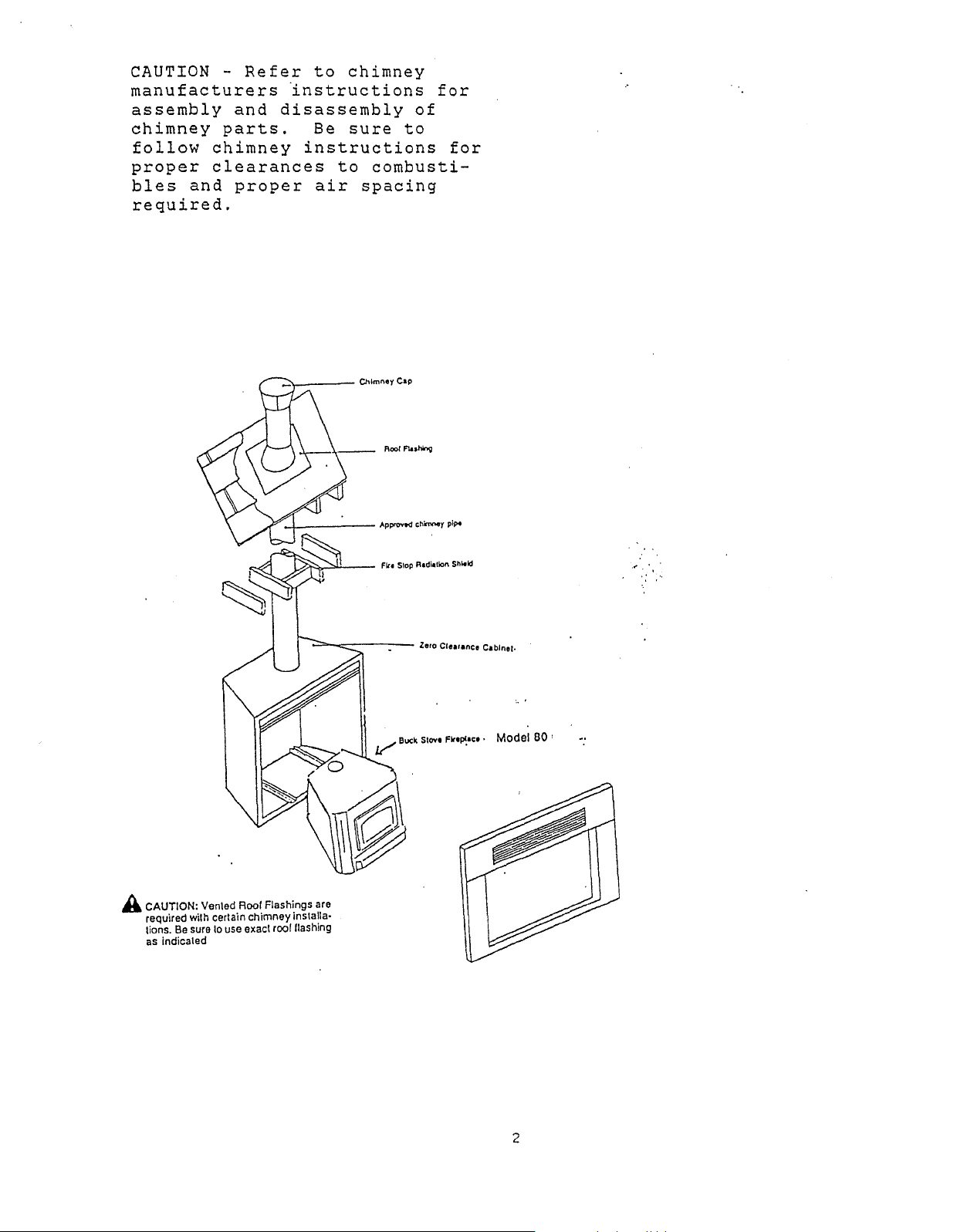
CAUTION manufacturers
assembly
chimney
follow
proper
bles
parts.
chimney
clearances
and
required.
Refer
and
proper
to
chimney
instructions
disassembly
Be
sure
instructions
to
air
spacing
for
of
to
for
combusti-
-',-
-1-
Chlmnoy
~pp<OvO<l
Cap
ch
.....
y
pipo
Model 80 '
A CAUTION: Vented Root Flashings are
required with certain chimney installa·
tions.
Be
suretouse exacl roor lIashing
as
indicated
2
Page 5

CAUTION: Do
model
of
listed
not
mix
chimney
Ch
imneyParts
parts
as
completely
a
fire.
for·an
may
resu1
instal~ation.
t.
Use
one
CAUTION:
Follow
install
instructions
A
major
required
of
utmost
dance
The
with
Zero
facilitate
tain
manufacturer's
Normally,
1)
Installation
ciated
BUCK
STOVE
Read
Chimney
the
cause
clearances
importance
these
Clearance
the
the
framing
Model
through
Manufacturer's
Cabinet,
will
of
void
chimney
instructions.
installation
installation
of
and
80
all
Stove,
the
related
(air
that
spaces)
these
Fireplace
clearances
the
Model
mortarwork,
into
the
of
these
Installation
and
Chimney
manufacturer's
fires
to
parts
Cabinet
of
a
BUCK
to
combustible
will
be
ZC-80
and
Hodel
accomplished
Fireplace
2)
ZC-80
instructions
carefully.
exactly.
as
described
warranty.
is
failure
combustible
be
installed
Hodel
ZC80
to
materials.
only
is
designed
STOVE MODEL-80 ONLY.
from
in
cabinet.
two
Cabinet
later
installation
Fireplace
Cabinet.
Failure
in
the
maintain
in
stages:
and
assoof
to
It
accor-
to
Main-
the
is
3
Page 6
INSTALLATION PRECAUTIONS
The
A.
following
Compliance
precautions
with
local
mandatory.
B. Be
component
C.
D.
hig'hest
flat
extend
building
14
clearance
tible
E.
down-draft.
for
F.
G.
careful
Use
The
roof
a
1/2
feet.
materials
A
rain
the
Maintain
The
parts
only
listed
chimney
point
or
up
minimum
within
must
cap
Use
type
Fireplace
not
to
damage
and
accessories.
approved
must
where
to
ten
The
be
at
must
chimney
extend
it
a
2/12
of
two
feet
maximum
maintained
all
be
the
factory
being
manufacturer's
Cabinet
homes.
H.
DO
NOT
designed
build
solely
a
for
fire
housing
are
building
unit
chimney
a
penetrates
pitch
feet
of
higher
the
height
between
points.
used
to
approved
installed.
clearances
is
not
directly
the
mandatory
codes
in
minimum
the
roof),
than
chimney:
is
42
terminate
intended
inside
BUCK
for
and
handling
pipes.
of
three
roof
and
any
The
feet.
the
chimney
the
rain
from
the
STOVE
a
safe
regulations
and
(three
the
portion
minimum
A
chimney
cap
cabinet.
for
use
Model
Hodel
installation:
unpacking
feet
feet
chimney
two-inch
and
which
in
ZC-80.
80.
above
above
must
of
height
any
to
is
mobile
is
the
a
the
is
combus-
prevent
approved
It
is
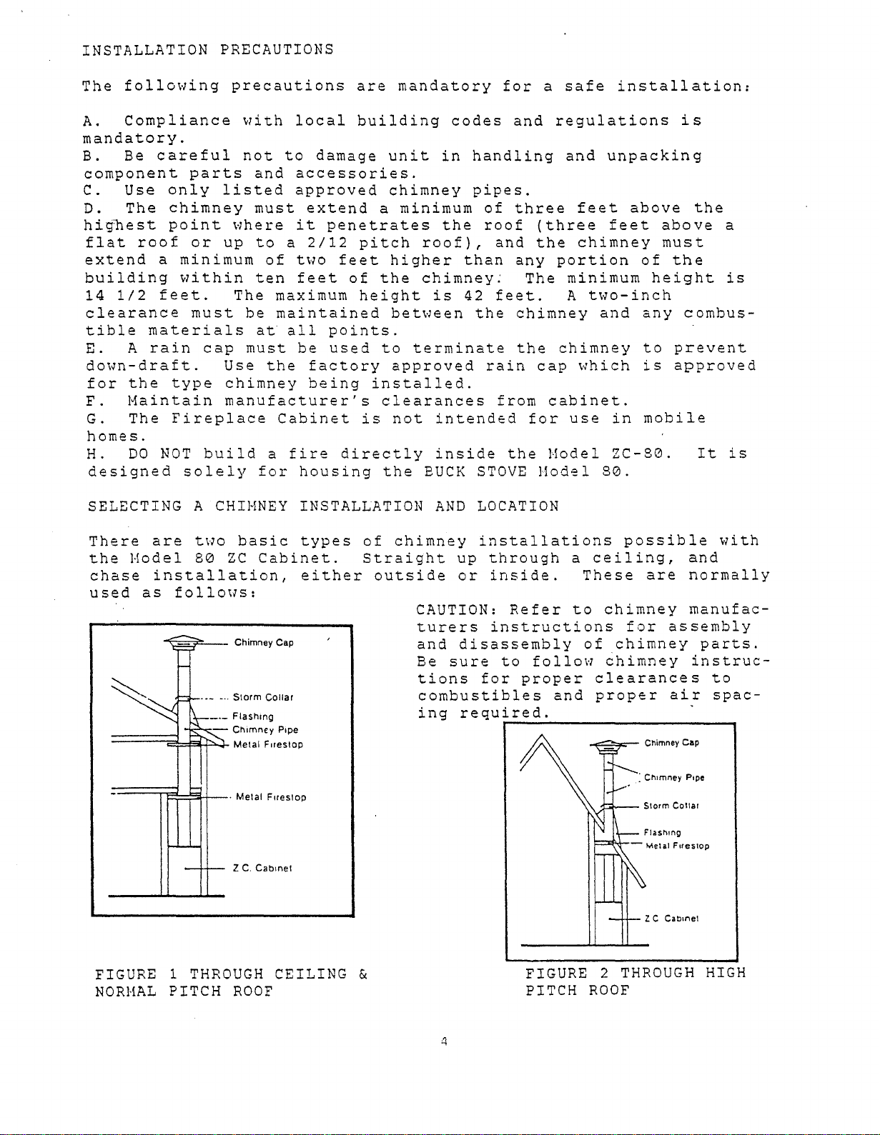
SELECTING A
There
the
chase
used
are
Hodel
installation,
as
~=::r=--
=====;:;;W~~
=
=====r~~U--.
CHIMNEY
two
80
follol1s:
-.-
•..
___
basic
ZC
Cabinet.
Chimney Cap
Storm
Collar
Flashing
Chimney
Metal
F,restop
Melal
Z
C.
Cabinet
INSTALLATION
types
either
Pipe
Forestop
of
chimney
Straight
outside
AND
LOCATION
installations
up
through
or
inside.
CAUTION:
turers
and
Be
tions
instructions
disassembly
sure
to
for
combustibles
ing
required.
r--------------,
Refer
follow
proper
a
to
and
possible
ceiling,
These
chimney
for
of
chimney
6himney
clearances
proper
-.=::::~-
- Melal
are
assembly
air
Chimney
Storm
Collar
Flashing
F"eslop
Z C
Cabinet
with
and
normally
manufac-
parts.
instruc-
to
spac-
Cap
FIGURE 1
NORMAL
THROUGH
PITCH
CEILING &
ROOF
FIGURE 2
PITCH
ROOF
THROUGH
HIGH
Page 7

A.
Straight
simple
inside
Refer
installation
an
existing
to
Figure
up
through
room,
3
if
ceiling:
normally
an
offset
and
used
in
iome
to
(See
when
clear
Figures
installing
cases,
an
1
and
in
new
obstruction
a
2).
Hodel
This
construction.
is
is
ZC-80
needed.
a
CAUTION-
instructions
of
ney
combustibles
4~¥--
1-1----
A=::lt'r----
\..>r--
A-"~-Ir---
"7'--::::--""<:''c-
chimney
instructions
Chimney Cap
Chimney
Storm
Collar
Flashing
Elbows
Adjustable
Metal
Fire
Stop
Refer
parts.
Pipe
Chimney
for
and
to
chimney
assembly
for
proper
Be
sure
proper
air
manufacturers
and
disassembly
to
follow
clearances
spacing
Wall
Strap
-f.,.....-1
chim-
to
required.
Chimney
- Flashing
Chase
Chimney Pipe
Z.C.
Cap
Cabinet
FIGURE
B.
Chase
built
is
open
cut
through
outside
through
the
chase,
wall.
stone
flue.
to
a
ant
to
building,
standing
where
building
room.
--w----
3 OFFSET
OBSTRUCTION
Installation:
specifically
from
and
the
with
Chases
or
wood
Occasionally,
stairwell.
read
as
flue
offsets
designs,
the
ceilings
against
wall,
the
are
to
the
chimney
there
that
are
Z.C.
Cabinet
TO
CLEAR
to
Hodel
and
the
and
front
commonly
give
they
When
are
must
used
or
to
(See
house
a
ZC-80
the
exterior
the.
Hodel
of
veneered
the
appearance
are
making
manufacturer's
specific
be
planned
within
locate
Figure
chimney.
to
the
roof.
wall
ZC-80
the
unit
built
a
chase
requirements
a
chase
the
4).
The
roof,
Normally,
of
is
flush
on
the
of
inside
installation,
instructions
for.
to
Hodel
FIGURE
A
chase
interior
eliminating
a
a
home.
located
with
outside
a
conventional
and
for
There
accommodate
ZC-80
4 EXTERIOR
WALL
is
an
of
chase
A
hole
in
the
the
interior
with
boxed
in,
it
prior
bracing
are
also
unusual
further
enclosure
a
the
is
built
is
bottom
brick,
fireplace
similar
is
import-
a
occasions
into
CHASE
chase
need
cut
to
free-
a
to
of
5
Page 8

FRAMING
CONSTRUCTION
Except
you
as
desire.
noted,
restrictions
sure
to
tion
that
place
than
these
your
to
done.
You
must
the
load
additional
of
plywood
hearth
Good
ensure
of
support,
or
look.
planning
therefore,
ZC-80
the
route,
ivill
be
roof-straight
contact
planning.
CHIMNEY
Position
A.
B.
Figure
C.
INSTALLATIONS
Hodel
Thoroughly
Layout
5).
If
chimney
plumbline,
of
D.
Model
Install
ZC-80
recommendations.
There
that
Hodel
be
this
2"
is
at
this
located
the
locate,
the
the
are,
must
clearance
ZC-80
forced
that
unit.
such
x
boards
essential
point
up,
your
Buck
ZC-80
clean
location
is
to
and
chimney
chimney
Hodel
however,
be
to
the
and
or
for
the
be
mark
adapter.
ZC-80
followed.
restrictions
correctly
relocate
floor
If
inadequate,
as
bracing.
is
for
you
the
chase.
Stove
chimney
area
on
the
installed
point
in
accordance
can
a
is
required
a
satisfactory
should
route
If
Dealer
where
floor
be
installed
few
clearance
See
are
at
the
it
after
of
adequate
the
A
wooden
in
have
the
chimney
you
cannot
for
installation
the
unit
and
through
on
ceiling
with
figures
met.
start
much
floor
order
decided
assistance
will
construct
a
ceiling,
directly
chimney
almost
and
framing
1
and
It
is
of
the
of
the
strength
will
base
to
get
constructed
installation,
where
will
follow
decide
with
as
follows:
be
placed.
base
drop
manufacturer's
anywhere
2
to
much
installawork
to
accept
require
a
raised
the
the
(See
over
make
wiser
is
Hodel
to
best
the
a
center
CAUTION:
building,
maximum
Base
for
finished
must
be
Follow
i.e.,
height
Wooden
FIGURE
Hodel
hearth
recessed
the
straight-up
follow
1
5'
""'1
:::~
Base
ZC-80
height-dimension
2
1/2"
instructions
or
chimney
Finished
Wall
Finished
A
Floorline
16"
__
19'/."
must
be
from
for
chase.
manufacturers
WARNING!
protector
The
extend
front
and
Hearth
mum.
is
~
level
with
(A)
finished
6
the
For
hearth
of
must
(Total
19
3/4"
or
Figure
wall.
type
chimney
minimum
instructions.
Install
only
extension
a minimum
the
fireplace
be
42
area
by
42
slightly
5.
Front
height
the
as
of
1/2"
to
1/2".)
you're
and
hearth
specified.
must
16"
opening
wide
be
covered
higher
of
cabinet
in
mini-
than
Page 9

Framing
place.
tion
ble.
prior
must
The
is
considerably
Therefore,
to
framing
be
accomplished
chimney
it
when
can
be
more
is
recommended
a
choice
after
installed
difficult
exists.
the
and,
that
Model
after
in
the
ZC-80
framing,
some
chimney
is
but
cases,
be
set
installa-
impossi-
installed
in
FIGURE
Above
sions
urements
1.
Before
etc.)
ing
the
6
(Figure
for
some
so
install
framing,
must
FIGURE 1·A:
16"
be
x
'~
LJ
Atlj<lcelll
Exlclior
6)
are
typical
removed
42
1/2"
Safety
extension.
~t:
±
noom
01
Cha:;e
framing
configurations.
accordingly.
combustible
to
outer
area
shield
for
Attach
shield
sheet
screws
lZ
rr~'Bl.lllzm<f1~mm_"
~
location
for
millboard
safety
using
metal
Locntion
floor
dimension
the
~\~
Interior
hearth
hearth
WARNING!
protector
The
extend
front
and
mum.
:Jl.
examples
These
coverings
of
extension.
hearth
a
of
must
with
are
(carpet,
unit
Install
only
extension
minimum
the
fireplace
be
42
depth
finished
framing,
the
as
specified.
of
1/2"
tiles,
hearth
must
16"
wide
dimen-
meas-
includ-
in
opening
mini-
FIGURE
brick
vertical
height
mum
combustibles
1-B:
or
as
metal
Safety
rock
shield
needed.
being
hearth
on
to
sure
the
shields
(Note:
Fit
Use
to
base.)
for
Cut
Installation
26
'Ga.
cover
Mini-
any
o
"'==~~--7'Attach
shield
sheet
7
safety
using
metal
scews
Page 10

2.
Set
unit
as
bustible
=.084/BTU/F
3.
Frame
framing.
A.
Adjacent
of
the
Cabinet
B.
The
and
C.
come
ures
41
1/2"
Framing
flush
i-A
Hodel
shown
material
2
the
Some
overall
with
and
ZC-80
in
H0F
ZC
side
high.
must
i-B).
Figure
3/4"
inches
Cabinet
minor
walls
trim
opening
protrude
the
unit
thick
minimum.
framing
panel.
back
in
place
i-A
and
millboard
usng
2"x
restrictions
must
be
dimensions
2
1/2"
of
the
i-B.
4"
at
to
ZC
and
You
studs
least
must
allow
Cabinet
attach
must
or
be
safety
place
equivalent
or
local
are
6"
from
at
for
trim
building
required:
the
least
finished
panel
shield
a
noncom-
K
outer
47
(See
Factor
1/2"
wall
to
code
edge
Hide
to
Fig-
8
Page 11

Chimney Cap
CAUTION!
Refer
manufacturers
assembly
chimney
follow
proper
bles
and
parts.
chimney
clearances
and
required.
disassembly
proper
to
chimney
instructions
Be
sure
instructions
to
combusti-
air
spacing
for
of
to
for
//?~--
Chimney Pipe
"Y~
.....
4-'::;"':~--
-+1----
2"
x."
Siudding
A Double
load
12" above
Singi. H
A Single Header
of
must
NOTE:
2"
Cabinet
Doubl. H
Header
cabinet.
der
Finished
(without
must
of
must
face
wall
bearing wall. This
••
front Iraming, vertical2"....
be turned flat.
in
front
••
der
be usedona
mustbedone
be used as
must
of
Z.C.
hood
panell.
part
·s
be
FIGURE 7 EXTERIOR
ROOF
OR
CHASE
WARNING!
protector
The
hearth
extend
front
and
must
mum.
9
a
of
Install
only
extension
minimum
the
fireplace
be
47
the
as
of
1/2"
hearth
specified.
must
16"
opening
wide
in
mini-
Page 12

ffi---
Chimney
Cap
CAUTION!
manufacturers
assembly
chimney
follow
proper
bles
parts.
chimney
clearances
and
required.
Refer
and
proper
to
chimney
instructions
disassembly
Be
sure
instructions
to
air
for
of
to
for
combusti-
spacing
0--\.--1-
---:f--
-+
Storm
Collar
Roof
Flashing
Chimney Pipe
,.....e;~~"'-7"'5..-s-'lt-ttt1--
-"'C-~7"''-?.-s-'S1'f--i-H-tt+f--
"-':H+f--t-+++H+--
Use
Fire
Metal Fire
A Double
load bearong
F.gure
Header
3.
2"
•
4"
A
Single
above
Vert.cal2"•
cabinet.
Code
Sheet
Slop
NOTE:
mustbeusedona
....
allasillustrated
Studding
Header
mustbeInstalled
4'''s
mustbeturned
Rock
in
flat.
FIGURE
8
CORNER
LOCATION FRAMING
Finished
in
Cabinet
trim
WARNING!
protector
The
hearth
extend
front
and
must
10
front
attached)
a
of
NOTE:
wall
must
of
face
(without
.
Install
only
extension
minimum
the
fireplace
be
47
of
hood
as
1/2"
be
2"
Z.C.
the
specified.
of
hearth
must
16"
wide
in
opening
mini-
Page 13

Install
down
on
the
over
pipe
ZC
to
the
~tarter
Cabinet.
cabinet
by
section
pushing
of
pipe
NOTE:
first
use
bottom
Maintain a 2
minimum
To
section
a
pipe
of
inch
clearance
ease
crimping
the
installation
of
pipe
inside
to
tool
chimney
the
and
of
the
Cabinet
crimp
liner.
the
Install
pushing
section
Cabinet.
Attach
ea.)
assure
pipe
down
of
sheet
to
stability.
pipe
pipe
to
over
metal
and
cabinet
the
on
the
clips
cabinet
by
starter
ZC
top
(2
to
WARNING!
air
spaces
around
with
rials.
11
Do
pipe
insulation
not
on
starter
top
pack
or
of
other
required
cabinet
section
or
mate-
Page 14

INSTALLING
tion
least
Shield
two
FIRESTOP
to'
the
8-penny
RADIATION
bottom
nails
per
of
SHIELD:
the
side.
framed
Nail
ceiling
the
firestop
opening
Radia-
using
at
CHIMNEY
ROOF
Frame
roof
clearance
between
opening
INSULATION
FIRES
SHIELD
Provides
2"
clearance
Clearance
and
INSTALLATION
CLEARANCE
a
square
maintaining
the
and
TOP
enclosing
opening
to
combustible
chimney
roofing
RADIATION
RADIATION
proper
between
clearance.
does
wall
INFORMATION
the
required
and
material.
not
app~y.
chimney
2".
in
materials
the
2"
framed
ROOF
/'
rr=
ATTIC
CEILING
ROOM
8"
Chimney
fits
between
12
standard
16"
OC
joists.
Page 15

Electrical
electrician
using
with
1.
2.
3.
through
net.
4.
5.
mounting
6.
local
Remove
Remove
Run
Tighten
Wire
Replace
No.
No.
the
Leave
procedures:
must
14
AWG
wiring
receptacle
receptacle
14
Field
4-6
Field
receptacle
box.
receptacle
wire
(with
AWG
inches
the
ground
codes.
cover.
from
wire
Connector
of
Connector
(black,
cover.
The
Cabinet
(See
mounting
directly
wire
ZC-80
wiring)
Figure
in
the
extending
around
white,
Cabinet
into
box.
from
lower
wire.
and
as
9)
house
is
the
home
minimum
right
out
ground)
not
wiring
side
of
and
pre-wired;
wiring.
in
accordance
in
of
the
box.
resecure
system
the
an
Cabi-
to
FIGURE 9
GROUND HOUSE WIRING TO STUD
POI'lER
HOOK-UP
TO
HOUSE
WIRING
13
Page 16

FINISHING
Finishing
can
accordance
CAUTION: Do
allowed
grilled
this
Cabinet
to
trim
area.
cannot
now
with
not
escape
panel
Also,
local
be
be
cover
from
is
the
blocked.
completed
building
any
the
provided
grilled
using
and
opening
openings
with
opening
Optional
Fire Code
Sheet Rock
the
fire
on
the
designed
the
at
desired
codes.
Cabinet;
trim
the
material
into
package
bottom
heat
the
unit.
to
front
in
must
cover
of
be
A
the
A
hearth
must
extend
minimum
front
place
of
opening.
mantel
tioned
14"
above
the
trim
Use
a
non-combusti-
ble
millboard
thermal
of
K=0.84
2HOFor
floor
millboard
protector
covered
combustible
such
as
tile,
extension
of
16"
the
must
a
minimum
the
kit
conductivity
BTUin./ft.
a
listed
protector.
or
may
with
marble,
etc.
to
a
in
fire-
The
be
posi-
top
hood.
having
floor
be
a
non-
material
of
of
The
slate,
a
Do
not
his
cover
opening
-R".,...:.<:"".l-o
t
ALL DIMENSIONS
MINIMUM
ALLOWED
SHOWN
FOR
ARE
WARRANTY
Page 17

INSTALLING
THE
MODEL
80
BUCK
STOVE
Install
A.
Carefully
cabinet
B.
Thoroughly
surrounding
C.
Ensure
cess.
D.
Remove
E.
Inspect
F.
Slide
way
to
under
G.
to
Turn
be
stack.
lowered.
within
unit
air
the
the
as
reinspect
intakes
environment.
that
protective
motor_and
the
back
stack
flue
follows:
clean
Cabinet
Buck
so
Stove
that
positioning
Push
exit
chimney
after
all
has
plastic
associated
the
downward
opening
finishing
masonry
not
Model
flue
nuts
connections,
is
mud
and
been
damaged
wrapping
hardware
80
into
exit
counter-clockwise
and
fit
(containing
completed.
debris
from
for
the
Cabinet
of
stove
evenly
the
vent
during
stove.
damage.
lines
until
damper).
outputs
from
allowing
cabinet
masonry
all
the
up
recessed
and
and
pro-
stack
lS
Page 18

H.
it
by
Install
to
using
panels
I.
Remove
exposing
cord
Plug
so
in
place
the
1"
in
receptacle.
it
pOHer
cover
the
Cabinet
screws
place.
cover
will
cord
plate.
trim
plate
fit
~
or
to
in
. ....
kit
finished
secure
from
Roll
inside
receptacle.
(See
attaching
framing
the
Cabinet
up
pOHer
of
cover
Figure
trim
box.
Re-
10).
Cover
Plate
o /
""",
Sheet
Metal
Screws
/
FIGURE
10
/
16
 Loading...