

New Buck Corporation 41, 50 Instruction Manual
"MEETS
1990
EPA
STANDARDS"
I
I
@
I
I
I
I
,--
--..
,
!
Ov.
0
MODEL
41
MODEL
50
FEATURES
PREPARATION
INSTALLATION
OPERATION MAINTENANCE SAFETY
Contact
your
Insurance company
for
coverage
and
Installation
Inspection
SAFETY NOTICE
If
this heater Is not properly Installed, a house fire may result. For
your
safety,
follow
the
Installation
directions.
Contact
local
buildingorfire
officials
about
restrictions
and
Installation
inspection
requirements
in
your
area.
tl0
L
This symbolonthe nameplate means the productisListed by Underwriters Laboratories.
Inc.
\'.!.bJ
File No. MH15931, MH15933,ULStandard No. 1482
Manufactured by New Buck Corp. - Spruce Pine,
NC
28777 - EFFECTIVE 6/1/90
PN-PI 4106608
Dear
Customer
WELCOMEtothe
NEW BUCK CORPORATION
family!
You have probably noticed that
most owner's manuals begin by offering congratulations. We want to reserve that courtesy
for you. You see, we are convinced, that after you
have used our products even for ashort
time, that
you
will want to congratulate yourself for making such a wise buying decision.
NEW
BUCK CORPORATION customers are urged to use this manual. The contents of
this manual
provides information on safety of stove operation and heating efficiency.
By
following the instructionsand suggestions outlined, youcan ensure yearsof safe, economical
heat tor yourself and your family.
It will also help you get a good return on your investment.
WELCOME
again to our family.
INTRODUCTION
SECTION
I:
SECTION
II:
SECTION III:
Section IV:
Section
V:
Section
VI:
Section VII:
Section VIII:
TABLE OF CONTENTS
Room Heater Features 3
Important Statements 4
Masonry Insert Installation 7
Minimum Clearances 8
Required Fireplace Dimensions 9
Tools for Installation 9
Installation Preparation
Fireplace Preparation 9
Heater Preparation 10
Installation Procedure-
(Direct Connect) 10
Positioning the Heater 10
Mounting the Trim Panels
10
Direct Connect Installation
11
Final Check 12
Freestanding Installation 13
Minimum Clearances 14
Tools for Installation 17
Installation Preparation 18
Determining the Chimney Location
..
19
Final Check 22
Mobile Home Installation. . . . . . . .
..
. 23
Parts Requirements
23
Minimum Clearances
24
Tools for Installation 26
Installation Preparation 26
Determining the Chimney Location . 28
Final Check
30
Safety
31
Operation 32
Building a Fire
32
Operating and Safety Tips
34
Guide to Burning Qualities of Wood
35
Helpful Hints
35
Manufacturer's Suggested
Preventive Maintenance 36
Chimney 36
Heater 36
Catalyst Inspection 37
Gasket Inspection 39
Catalyst Replacement
38
Gasket Replacement
40
Electrical Operation . . . . . . . . . . . . . . . . . .
..
.
41
Troubleshooting Guide
42
WARRANTY - Heater. . . . . . . . . . . . . . . . . . .
..
. Rear Cover
Catalysts ' Insert
Page 1

SECTION I
The
New
Buck Corporation room heater Models
41
and 50 are safe and efficient heating
systems when installed and operated
as
specified in these instructions andasstipulated
on the operation and installation labels affixed to the unit. The unit
is
designed to burn
wood fuel only.
The installation and operating instructions found
in
this manual have been developedthrough
extensive laboratory testing and
in
the field experience. The procedures outlined MUST
be followed exactlytoensure a safe and operational installationaswell as to validate your
warranty.
Throughout the manual, you will see this symbol
A .This indicates areas of importance
regarding safety. Please make a special note
of
these areas. Read these instructions careful-
ly before installing your heater and keep them with your important papers for future
reference.
FIGURE 1
PHYSICAL FEATURES
Install and use onlyinaccordance with the manufacturer's installation and operating
in-
structions. Do not connect this unit to a chimney flue serving another appliance.
Page 2
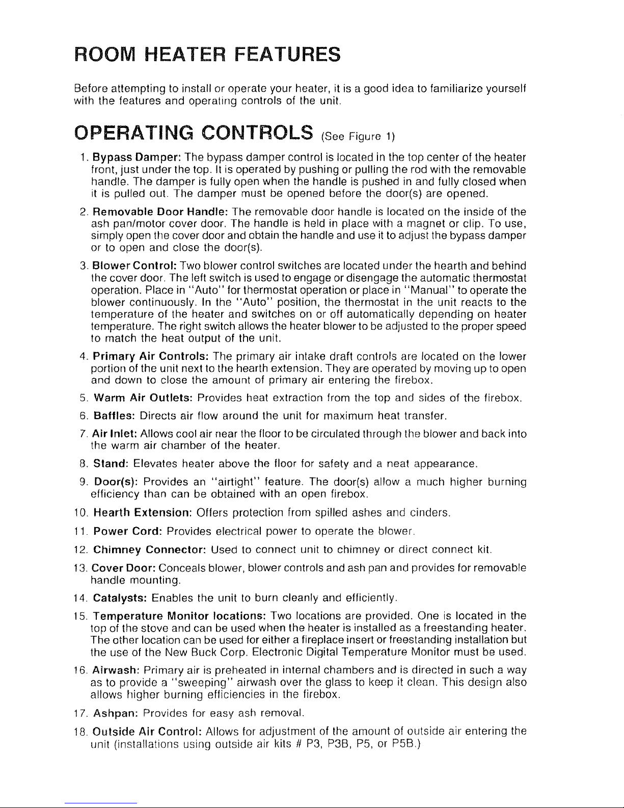
ROOM HEATER FEATURES
Before attempting to install or operate your heater, it is a good idea to familiarize yourself
with the features and operating controls of the unit.
OPERATING CONTROLS (See Figure
1)
1.
Bypass
Damper:
The bypass damper control is locatedinthe top center of the heater
front, just under the top.
It
is operated by pushing or pulling the rod with the removable
tlandle. The damper
is
fully open when the handle is pushed in and fully closed when
it is pulled out. The damper must be opened before the door(s) are opened.
2.
Removable
Door
Handle: The removable door handleislocated
on
the inside of the
ash pan/motor cover door. The handle is held
in
place with a magnet or clip. To use,
simply open the cover door and obtain the handle and useit
to
adjust the bypass damper
or
to
open and close the door(s).
3.
Blower
Control:
Two blower control switches are located under the hearth and behind
the cover door. The left switch
is
used to engage or disengage the automatic thermostat
operation. Place in
"Auto"
for thermostat operation or placein"Manual"
to operate the
blower continuously.
In
the
"Auto"
position, the thermostatinthe unit reactstothe
temperature of the heater and switches
on
or off automatically depending on heater
temperature. The right switch allows the heater blower to
be
adjustedtothe proper speed
to match the heat output of the unit.
4.
Primary
Air
Controls:
The primary air intake draft controls are located on the lower
portion of the unit next to the hearth extension. They are operated
by
moving up to open
and down to close the amount of primary air entering the
firebox.
5.
Warm
Air
Outlets:
Provides heat extraction from the top and sides of the firebox.
6.
Baffles:
Directs air flow around the unit for maximum heat transfer.
7.
Air
Inlet: Allows cool air near the floor to be circulated ttHough the blower and back into
the warm air chamber of the heater.
8.
Stand:
Elevates heater above the floor for safety and a neat appearance.
9.
Door(s): Provides
an
"airtight"
feature. The door(s) allow a much higher burning
efficiency than can be obtained with
an
open firebox.
10.
Hearth
Extension:
Offers protection from spilled ashes and cinders.
11.
Power
Cord:
Provides electrical power to operate the blower.
12.
Chimney
Connector:
Used to connect unittochimney or direct connect kit.
13.
Cover
Door:
Conceals blower, blower controls and ash pan and provides for removable
handle mounting.
14.
Catalysts:
Enables the unit to burn cleanly and efficiently.
15.
Temperature
Monitor
locations:
Two locations are provided. One is locatedinthe
top of the stove and can
be
used when the heater is installedasa freestanding heater.
The other location can be used for either a fireplace insert or freestanding installation but
the use of the New Buck Corp. Electronic Digital Temperature Monitor must be used.
16.
Airwash:
Primary airispreheatedininternal chambers and is directed in such a way
as to provide a
"sweeping"
airwash over the glass to keep it clean. This design also
allows higher burning efficiencies in the firebox.
17.
Ashpan:
Provides for easy ash removal.
18.
Outside
Air
Control:
Allows for adjustment of the amount of outside air entering the
unit (installations using outside air kits
II
P3,
P3B, P5, or P5B.)
Page 3
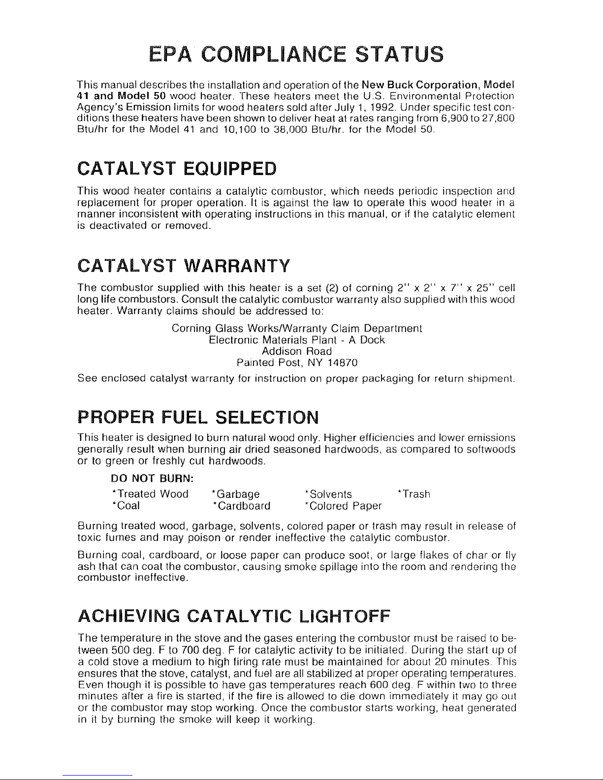
EPA COMPLIANCE STATUS
This manual describes the installation andoperation of the
New
Buck
Corporation,
Model
41
and
Model
50
wood heater. These healers meet the U.S. Environmental Protection
Agency's Emission limits for wood heaters sold after July
1, 1992. Under specific test con-
ditions these heaters have been stlowntodeliver heatatrates ranging from
6,900to27,800
Btu/hI' for the Model
41
and
10,100to38,000
Btu/hr. for the Model 50.
CATALYST
EQUIPPED
This wood heater contains a catalytic combustor, which needs periodic inspection and
replacement for proper operation. It is against the law to operate this wood heater
in
a
manner inconsistent with operating instructions
in
this manual, or if the catalytic element
is deactivated or removed.
CATAL
YST
WARRANTY
The combustor supplied with this heater is a set (2)01corning
2"x2"
x
7"
x
25"
cell
long life combustors. Consult the catalytic combustor warranty also
supplied with this wood
heater. Warranty claims should be addressed to:
Corning Glass Works/Warranty Claim Department
Electronic Materials Plant -
A Dock
Addison Road
Painted Post, NY
14870
See enclosed catalyst warranty
101'
instruction on proper packaging for return shipment.
PROPER FUEL SELECTION
'Trash
'Solvents
*Colored Paper
*Garbage
'Cardboard
This heater is designedtoburn natural wood only. Higher efficiencies and lower emissions
generally result when burning air dried seasoned hardwoods,
as
comparedtosoftwoods
ortogreen or freshly cut hardwoods.
DO
NOT BURN:
'Treated
Wood
'Coal
Burning treated wood, garbage, solvents, colored paper or trash may result in release
of
toxic fumes and may poison or render ineffective the catalytic combustor.
Burning coal, cardboard, or loose paper can produce
soot, or large flakes of char or fly
ash that can coat the combustor, causing smoke spillage into the room and rendering the
combustor ineffective.
ACHIEVING
CA
TAL
YTIC LIGHTOFF
The
temperatureinthe stove and the gases entering the combustor must be raisedtobe-
tween 500 deg. F to 700 deg. F for catalytic activity to be initiated. During the start up of
a cold stove a medium to high firing rate must be maintained for about
20
minutes. This
ensures that the stove, catalyst, and fuel
are
all stabilized at proper operating temperatures.
Even
HlOUgtl
it is possible to have gas temperatures reach
600
deg. F within twotothree
minutes after a fire is started, if the
1ire
is alfowed to die down immediatefy it may go out
or
the combustor may stop working. Once the combustor starts working, heat generated
in it by burning the smoke will keep it working.
Page 4
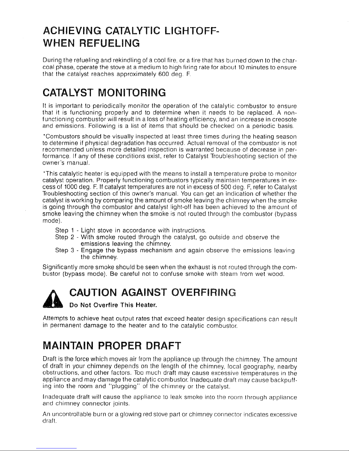
ACHIEVING
CATALYTIC LIGHTOFF-
WHEN REFUELING
During the refueling and rekindling of a cool fire, or a fire that has burned down to the charcoal phase, operate the stoveata mediumtohigh firing rate for about10minutestoensure
that the catalyst reaches approximately 600 deg.
F.
CATALYST MONITORING
It
is
important to periodically monitor the operation of the catalytic combustor to ensure
that it is functioning properly andtodetermine when it needs to be replaced. A non·
functioning combustor will result in a loss of heating efficiency, andanincrease in creosote
and emissions. Following is a list of items that should be checked on a periodic basis.
'Combustors should be visually inspected at least three times during the heating season
to
determine if physical degradation has occurred. Actual removal of the combustor is not
recommended unless more detailed inspection is warranted because of decrease in performance. If any of these conditions exist, refer
to
Catalyst Troubleshooting section of the
owner's manual.
'This
catalytic heater is equipped with the means to install a temperature probetomonitor
catalyst operation. Properly functioning combustors typically maintain temperatures
in excess of 1000 deg.F.If catalyst temperatures are not in excess of 500 deg.F,refertoCatalyst
Troubleshooting section of this owner's manual.
You
can get
an
indication of whether the
catalystisworking by comparing the amount of smoke leaving the chimney when the smoke
is
going through the combustor and catalyst light-off has been achievedtothe amount of
smoke leaving the chimney when the smoke is not routed through the combustor (bypass
mode).
Step 1
- Light stove in accordance with instructions,
Step 2
- With smoke routed through the catalyst, go outside and observe the
emissior,s leaving the chimney.
Step 3
- Engage the bypass mechanism and again observe the emissions leaving
the chimney.
Significantly more smoke should be seen when the exhaust
is
not routed through the com·
bustor (bypass mode). Be careful not to confuse smoke with steam from wet wood.
Attempts to achieve heat output rates that exceed heater design specifications can result
in
permanent damage to the heater and to the catalytic combustor.
MAINTAIN PROPER DRAFT
Draft is the force
which
moves air from the appliance up through the chimney. The amount
of draft in your
chimney
depends on the length of the chimney, local geography, nearby
obstructions, and other factors.
Too
much draft may cause excessive temperatures in the
appliance and may damage the catalytic combustor. Inadequate draft may cause backpuffing into the room and
"plugging"
of the chimney or the catalyst.
Inadequate draft will cause the appliance
to
leak smoke into the room through appliance
and chimney connector joints.
An uncontrollable burn or a glowing red stove part or chimney connector inclicates excessive
draft.
Page 5

ASH
REMOVAL
Whenever ashes build upinthe
firebox and when the fire has burned down and cooled,
remove excess ashes. Leave
an
ash bed approximately 1inch deeponthe firebox bottom
to help maintain a hot charcoal bed.
Ashes should be placed
in
a metal container with a tight
mUng
lid. The closed container
of ashes should be placed
on
a noncombustible floor oronthe ground, away from all com·
bustible materials, pending final disposal. The ashes shouldberetainedinthe closed can·
tainer until all cinders have thoroughly cooled.
Page 6
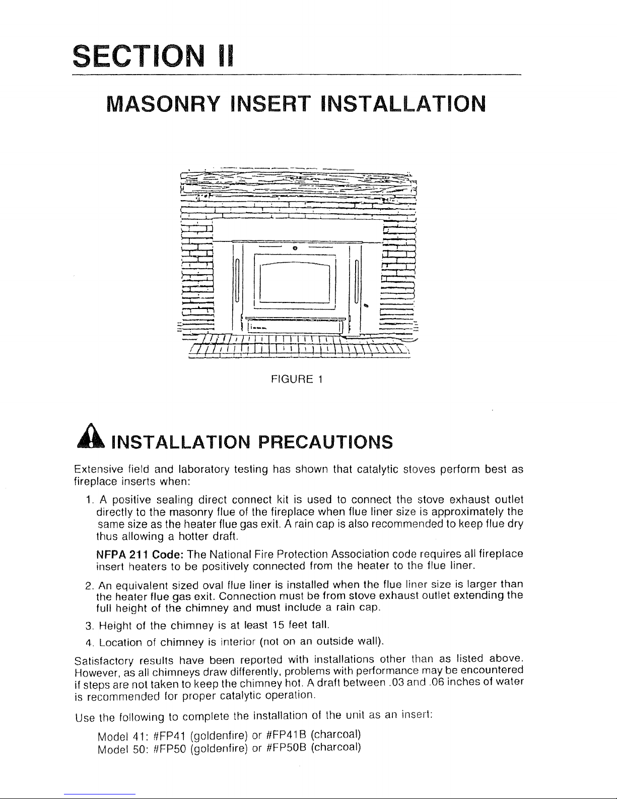
SECTION
II
MASONRY INSERT INSTALLATION
, .
.,-,~------
~
I
• • •
-
..
!
\
I
.
Q
I
~
• 1
~
~I
~
----
:=::
: 1
I
,
\
I
,
.
n
I
...
\
I
I
::
i
..
4
!
;;;;;:
;:;:::'
-
-
1
fi._-
If
\
r~.
I
.'21
-
,
:
jI
I
I
I
I
r
IIT
I
':
i
!
,
FIGURE 1
A
INSTALLATION
PRECAUTIONS
Extensive fierd and laboratory testing has shown that catalytic stoves perform best as
fireplace inserts when:
1.
A positive sealing direct connect kit is usedtoconnect the stove exhaust outlet
directly to the masonry flue of the fireplace when flue liner size is approximately the
same size
as
the heater flue gas exit. A rain cap is also recommended to keep flue dry
thus allowing a hotter draft.
NFPA 211
Code: The National Fire Protection Association code requires all fireplace
insert heaters to be positively connected from the heater to the flue liner.
2.
An
equivalent sized oval flue linerisinstalled when the flue liner size is larger than
the heater flue gas exit. Connection must be from stove exhaust outlet extending the
full height of the chimney and must include a rain cap.
3.
Height of the chimney is at least
15
feet tall.
4.
Location of chimney is interior (not
on
an outside wall).
Satisfactory results have been reported with installations other than
as
listed above.
However,
as
all chimneys draw differently, problems with performance may be encountered
if steps are not taken to keep the chimney hot. A draft between .03 and ,06 inches of water
is recommended for proper catalytic operation.
Use
Ole
followingtocomplete the installation of the unit as an insert:
Model 41: #FP41 (goldenfire) or
tlFP41 B (charcoal)
Model 50: flFP50 (goldenfire) or #FP50B (charcoal)
Page 7
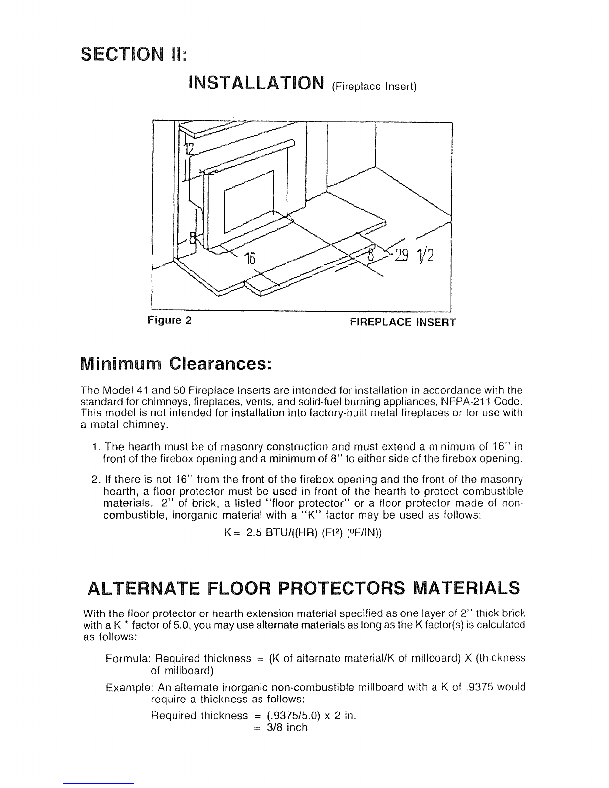
SECTION II:
INSTALLATION (Fireplace Insert)
Figure
2 FIREPLACE INSERT
Minimum
Clearances:
The
Model41and
50 Fireplace Inserts are intended for installation in accordance with the
standard for chimneys, fireplaces, vents, and solid-fuel burning appliances,
NFPA-211 Code.
This
model is not intended for installation into factory-built metal fireplaces or for use with
a metal chimney.
1.
The
hearth must be of masonry construction and must extend a
minimum
of
16"
in
front of the firebox opening and a
minimum
of8"to either side of tbe firebox opening.
2.
If
there is not 16" from the front of the firebox opening and the front of the masonry
hearth, a floor protector
must
be used in front of the hearth to protect combustible
materials.
2"
of brick, a listed
"floor
protector"
or a floor protector made of non-
combustible, inorganic material with a
"K"
factor may be used as follows:
K = 2.5 BTU/((HR) (FP) (OF/IN))
ALTERNATE
FLOOR PROTECTORS MATERIALS
With the floor protector or hearth extension material specified as one layer of2"thick brick
with a K * factor of 5.0, you may use alternate materialsaslong as the K factor(s) iscalculated
as
follows:
Formula: Required thickness
:=
(K
of aiternate material/K of millboard) X (thickness
of millboard)
Example:
An alternate inorganic non-combustible millboard with a K of .9375 would
require a thickness as follows:
Required thickness
= (.9375/5.0) x 2 in.
==
3/8 inch
Page 8
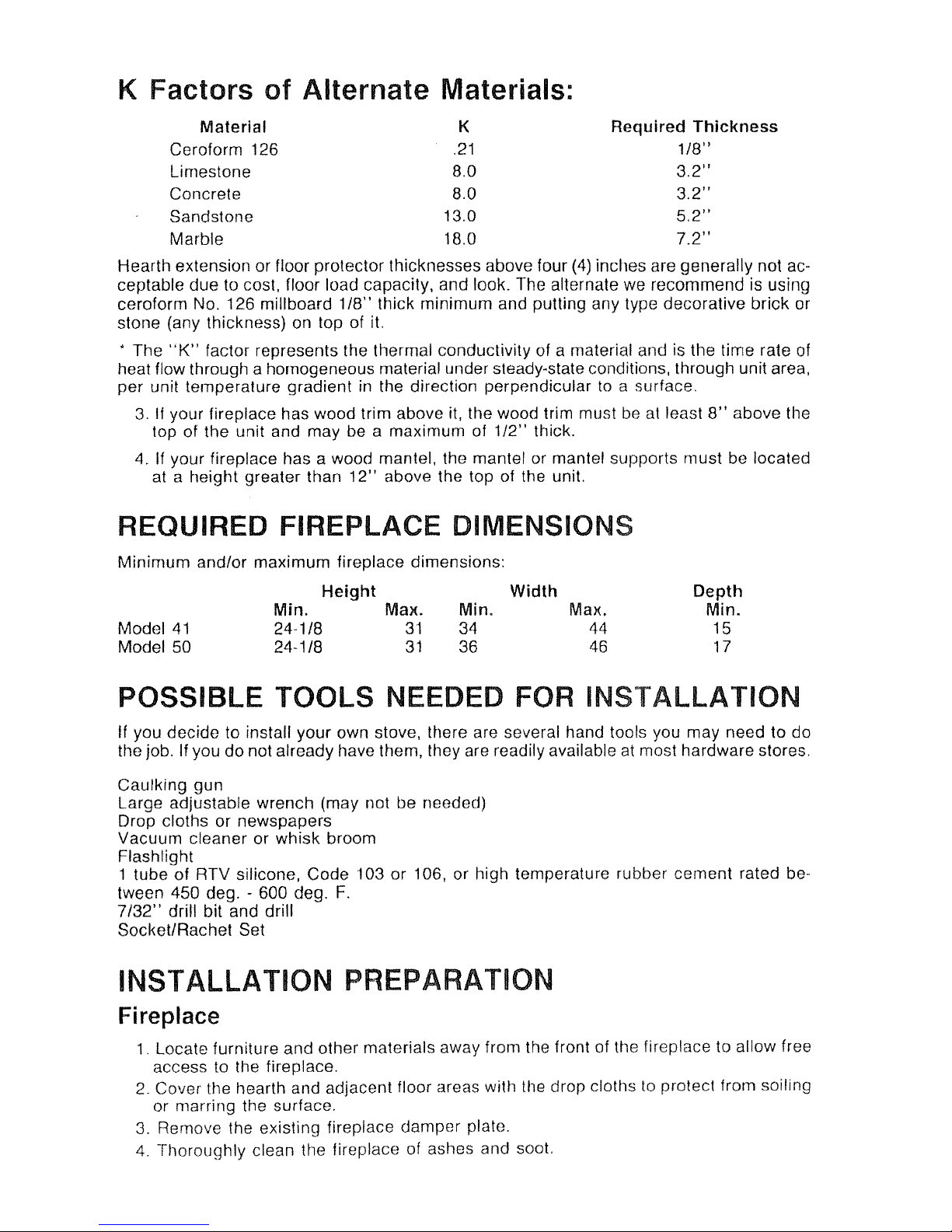
K
Factors
of
Alternate
Materials:
Material
K
Required
Thickness
Coroform 126
.21
1/8"
limestone
8.0
3.2"
Concrete 8.0
3.2"
Sandstone 13.0
5.2"
Marble 18.0
7.2"
Hearth extension or floor protector thicknesses above four
(4)
inches are generally not ac-
ceptable due to cost, floor load capacity, and look. The alternate we recommendisusing
ceroform No. 126 millboard
1/8"
thick minimum and putting any type decorative brick or
stone (any thickness) on top of
it.
* The
"K"
factor represents the thermal conductivity of a material and is the time rate
of
heat flow through a homogeneous material under steady-state conditions, through unit area,
per unit temperature gradient in the direction perpendicular
to
a surface.
3.
If
your fireplace has wood trim above it, the wood trim mustbeat
least
8"
above the
top of the unit and may be a maximum of
1/2"
thick.
4. If your fireplace has a wood mantel, the mantel or mantel supports must
be
located
at
a height greater than
12"
above the top of the unit.
REQUIRED FIREPLACE DIMENSIONS
Minimum and/or maximum fireplace dimensions:
Min.
24-1/8
24-1/8
Model
41
Model 50
Height
Max.
31
31
Min.
34
36
Width
Max.
44
46
Depth
Min.
15
17
POSSIBLE TOOLS NEEDED FOR
INSTALLATION
If you decide to install your own stove, there are several hand tools you may need to do
the job.
If you donot already have them, they are readily available
at
most hardware stores.
Caulking gun
large
adjustable wrench (may not be needed)
Drop cloths or newspapers
Vacuum cleaner or whisk broom
Flashlight
1 tube of RTV silicone, Code 103 or 106, or high temperature rubber cement rated
be-
tween 450 deg. - 600 deg.
F.
7/32"
drill bit and drill
Socket/Rachet Set
INSTALLATION PREPARATION
Fireplace
1.
locate
furniture and other materials away from the front of the fireplace to allow free
access to the fireplace.
2.
Cover
tt"le
tlearth and adjacent floor areas with the drop cloths to prolect from soiling
or marring the surface,
3.
Remove the existing fireplace
dampm
plate.
4.
Thoroughly clean the fireplace of ashes and soot.
Page 9
F'IR£JU.(!
QJTAlAY
'-'-'
,
I
5.
Check the chimney and smoke chamber for excessive buildups of creosote or
soot. Also, check for obstructions, such
as
birds' nest.ffthe chimney is excessively
dirty, clean it, or tlave someone clean it
professfonally BEFORE installing or using
the room heater.
6.
If the fireplace has an ash
dump
or outside air provision, these must be sealed off
with metal or tightly packed non-cornbustible insulation to prevent this cold air from
entering the fireplace chamber.
Heater
Preparation
1.
Remove the protective plastic wrapping from the stove.
2. Inspect the unit for any obvious physical damage.
3. Plug the power cord into a 115 VAC outlet to test the motor and fan. Place the blower
control in the
"MANUAL"
position to test.
4.
Check
the primary air draft controls to ensure that they slide freely.
5. Check the operations of the
damper
control to ensure that it will open and close
properly.
INSTALLATION
Procedure
(Use a Listed DirectorPositive Connect)
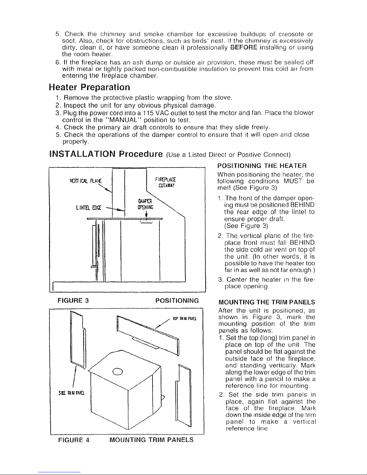
POSITIONING THE HEATER
When positioning the heater, the
following conditions MUST be
met! (See Figure
3)
1.
The front of the damper opening mustbepositioned BEHIND
the rear edge of the lintel to
ensure proper draft.
(See Figure
3)
2.
The vertical plane of the fire-
place front must fall BEHIND
the side cold air vent on top of
the unit. (In other word
s,
it is
possible to have the heatertoo
far in
as
well as not far
enough)
3.
Center the heaterinthe fire-
place opening.
FIGURE 3
~
I
5n:lUI
mo.
POSITIONING
MOUNTING THE TRIM PANELS
After the unit is positioned, as
shown in Figure
3,
mark the
mounting
position of the trim
panels as follows:
1.
Set the top (long) trim panel
in
place on top of the unit. The
panel should be flat against the
outside face of the fireplace,
and
standing vertically. Mark
along the lower edge of the trim
panel with a pencil to make a
reference
line for mounting.
2.
Set the side trim panels in
place, again flat against the
face of the fireplace. Mark
down the inside edge of the trim
panel
to
make
a
vertical
reference line.
FIGURE 4
MOUNTING TRIM PANELS
Page 10
3.
Slide the unit out of the fireplace far enough to
work
behind the trim
parel
reference
lines.
4.
CAUTION: If
optional
fireplace trim kit brass will be
used
on the trim panels, set the
trim panels out
5/16"
to allow for brass overhang.
5.
Mount
the side
trim
panels. (See Figure 4)
a.
Position
the
trim panel on the reference line.
b. Drill
Mounting
Holesincenteroftrim panels
mounting
brackets to allow for
adjustment in
and
out
if necessary.
c.
Mount
the trim panel
using
the self-tapping screws provided.
6.
Mount
top tfim
paneltoside panels with screws provided as indicated in Figure
4.
7.Ifdesired obtain optional brass trim from box and assemble using an
"ell"
bracket in each
corner where the
top
and side trim joins. Tighten set screws
joining
trim together.
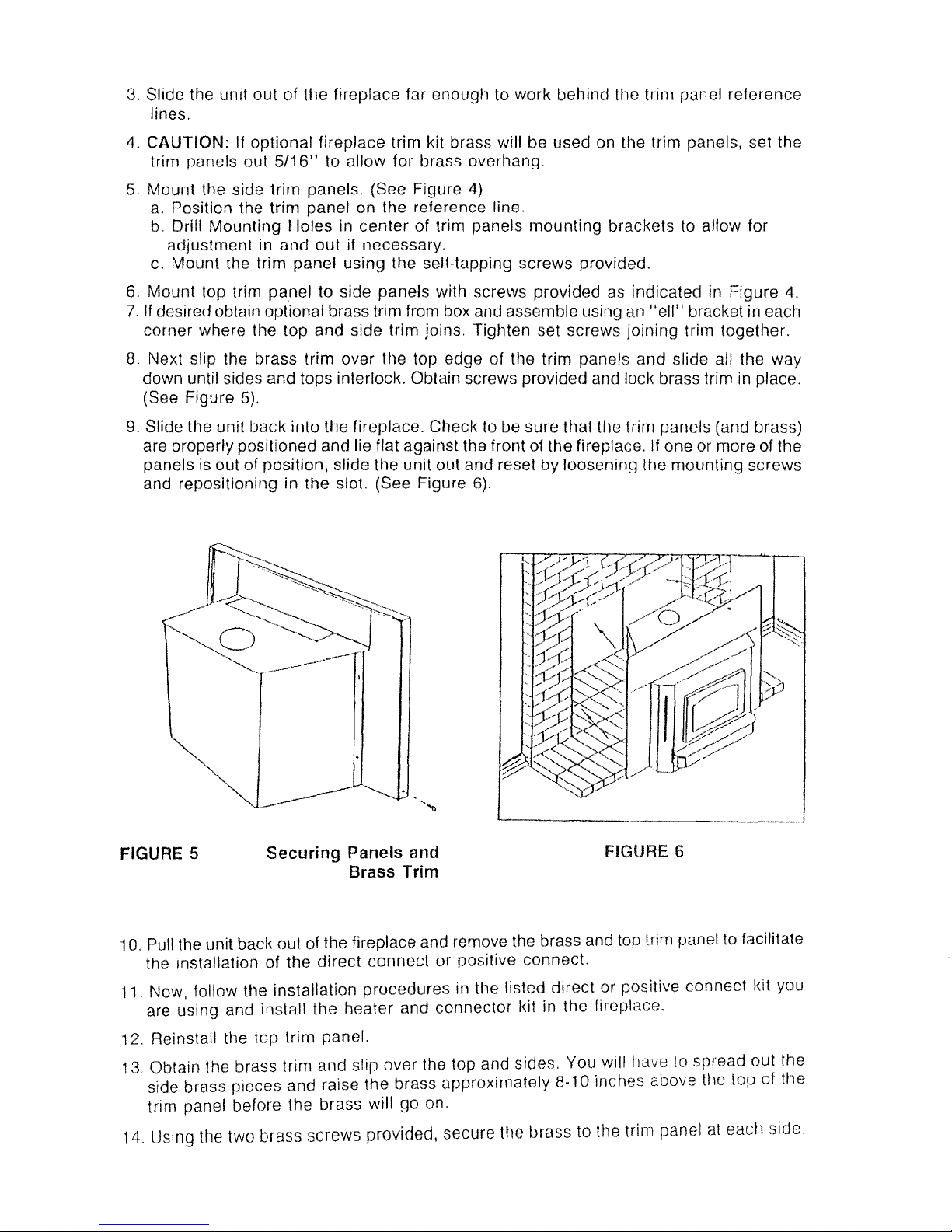
8. Next slip the brass
trim
over the top edge of the trim panels and slide all the way
down until sides
and
tops interlock. Obtain screws provided and lock brass trim in place.
(See
Figure
5).
9. Slide the
unit
back
into the fireplace. Checl< to be sure that the trim panels (and brass)
are properly positioned and lie flat against the front of
the
fireplace. If one or
more
of the
panels is out of position, slide the unit out and resetbyloosening the
mounting
screws
and repositioning in
the
slot. (See Figure
6).
FIGURE 5
Securing Panels and
Brass Trim
FIGURE 6
10. Pull the unit back out of the fireplace and remove the brass and top trim panel to facilitate
the installation of
the direct
connect
or positive connect.
11. Now, follow
tt1e
installation
procedures
in the listed
direct
or positive
connect
kit you
are
using
and install
the
heater and
connector
kit in the fireplace.
12.
Reinstan the top trim panel.
13. Obtain the brass
trim and slip over
1t1e
top and sides. You will have to spread out the
side brass pieces
and
raise
the
brass
approximately
8-10 inches above the
top
of the
trim panel before the brass will go on.
14. Using the two brass
screws
provided, secure the brass to the trim panelateach side.
Page 11
FINAL CHECK
1.
Recheck the specified clearances.
2.
Remove all foreign material from the firebox area.
3.
Open the primary air drafts and damper bypass.
4.
Plug the power cord into a
115
VAC outlet.
5.
Place crumpled pieces of newspaper in the stove. Light it and close the doors.
Ensure that the stove draws properly through the primary drafts.
6.
Check for smoke leaks around the doors.
7.
Open the doors and check for smoke escaping from the front of the stove. Smoking
usually indicates a defective or poorly positioned chimney. Some chimneys with a
marginal draft can be preheated by lighting newspaper and holding it near the open
damper with a poker or fire tong. Once the chimney heats up, a proper draft can
usually be obtained.
If a thorough review of the Troubleshooting Guide
in
the rear of the manual does not reveal
the problem, contact your dealer for assistance.
NOTE:
The unit is painted with a specially formulated high temperature paint that cures
during the first two
or
three firings. You may notice a slight smoking effect and an odor
of burning paint when you build the first fires. This is normal and is not a cause for alarm.
In
some cases, these fumes will activate a smoke alarm. Cracking a window near the unit
will allow these fumes to escape.
DO
NOT build a large, roaring fire until this curing
is
complete or the heater finish may be damaged.
Page 12
SECTION III
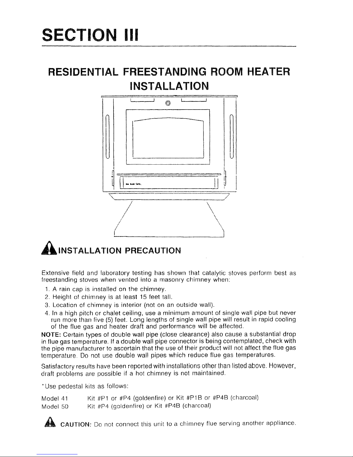
RESIDENTIAL FREESTANDING ROOM HEATER
INSTALLATION
-
@
-
',._-_--:-
..............
7
II
\
/ -'J
(
'-----
AINSTALLATION
PRECAUTION
Extensive field and laboratory testing has shown that catalytic stoves perform best as
freestanding stoves when vented into a masonry chimney when:
1.
A rain cap is installed on the chimney.
2.
Height of
chimney
is at least 15 feet tall.
3. Location of
chimney
is interior (not on an outside wall).
4. In a high pitch or chalet ceiling, use a minimum amount of single wall pipe but never
run more than
five (5) feet. Long lengths of single wall pipe will result in rapid cooling
of the flue gas
and
heater draft and performance will be affected.
NOTE: Certain types of double wall pipe (close clearance) also cause a substantial
drop
in flue gas temperature. If a
double
wall pipe connector is being contemplated, check with
the pipe manufacturer
to
ascertain that the use of their product will not affect the flue gas
temperature Do not use
double
wall pipes which reduce flue gas temperatures.
Satisfactory results have been reported with installationsother
Ulan
listed above. However,
draft problems are possible if a hot chimney is not maintained
.
•
Use pedestal kfls as follows:
Model
41
Model 50
Kit
ilP1
or
#P4 (goldenfire)orKit #P1 B or ilP4B (charcoal)
Kit
ttP4 (goldenfire) or Kit #P4B (charcoal)
A CAUTION:
Do
not connect this unit to a chimney flue serving another appliance.
Page 13

MODEL
41
Minimum
Clearances
The
New
Buck
Corporation
Model
41
must
be installed in compliance with the instruc-
tions contained in this manual.
Clearance
from
combustible
walls
and
ceilings.
The
minimum
lateral distance between any partofthe room heater and combustible walls
is shown in Figures 1, 2, 3,
4,
5 and
6.
l6-
1m:
o
IIl:J6I<:tb
SHJIIi
,!j£
14II0
ll..fAAIHI
TO
00iiJJ5f
laL
'I'U.
16-1/2
0
I
16
34
rum
U
I'ml'tCroR
IIIl11l1iW
SIZE
37
~
MODEL
41
MODEL
41
FIGURE 1 Wall
Installation
FIGURE 2
Corner
Installation
FLOOR PROTECTION
If
a freestanding modelisto be installed on a combustible floor, a noncombustible pad
must be placed
below
it to protect the floor from burning material from the stove. The pad
must be 37
inches
wide by34inches deep. U.L. tests were conducted without a floor pro
..
tector. Therefore, the protector can be of
any
thickness and any
"k"
factor.
The unit
must
be positioned on the pad so that there is a minimum of
16"
from the front
of the door
opening
to the front of the pad, and a minimum of
8"
measured horizontally
from the sides of the fuel loading and ash removal openings to the sides of the pad.
NOTE: For clearance reductions using wall protectors, refer to the NFPA -211 Code.
Page 14

Close
clearance
installations
using
2100
deg.
HT Metal Fab
"Type
TG"
chimney.
12
O~
/<
lW
I~W37
ttIT[ :
DIM){;
K:tlS
9n'IN
N{
III
IN
lIJJJ
a.ENWIT
TO
CCMl!:iT
IIll
ro
.
MODEL
41
10
FIGURE 3
I
r--,
U
MODEL
41
Wall
Installation
FIGURE 4
Corner
Installation
Close
clearance
installations
using
6"
Simpson
Dura-Vent
double
wall
chimney
con-
nector
"Type
DVL"
and
6"
Simpson
Dura-Vent
2100 Deg. HI.
"Type
DP"
chimney.
1
o
FUlR
rnmmm
IWlfl4.lll
SIZE
8
htJTE
:
o
1lf1lS
100
9fJIl
AI{
IIIHIllJlI
D.1JOOlI
m
romsT
llif
IW.L.
6
FIGURE 5
MODEL
41
Wall
Installation
FIGURE 6
MODEL
41
Corner
Installation
Page 15
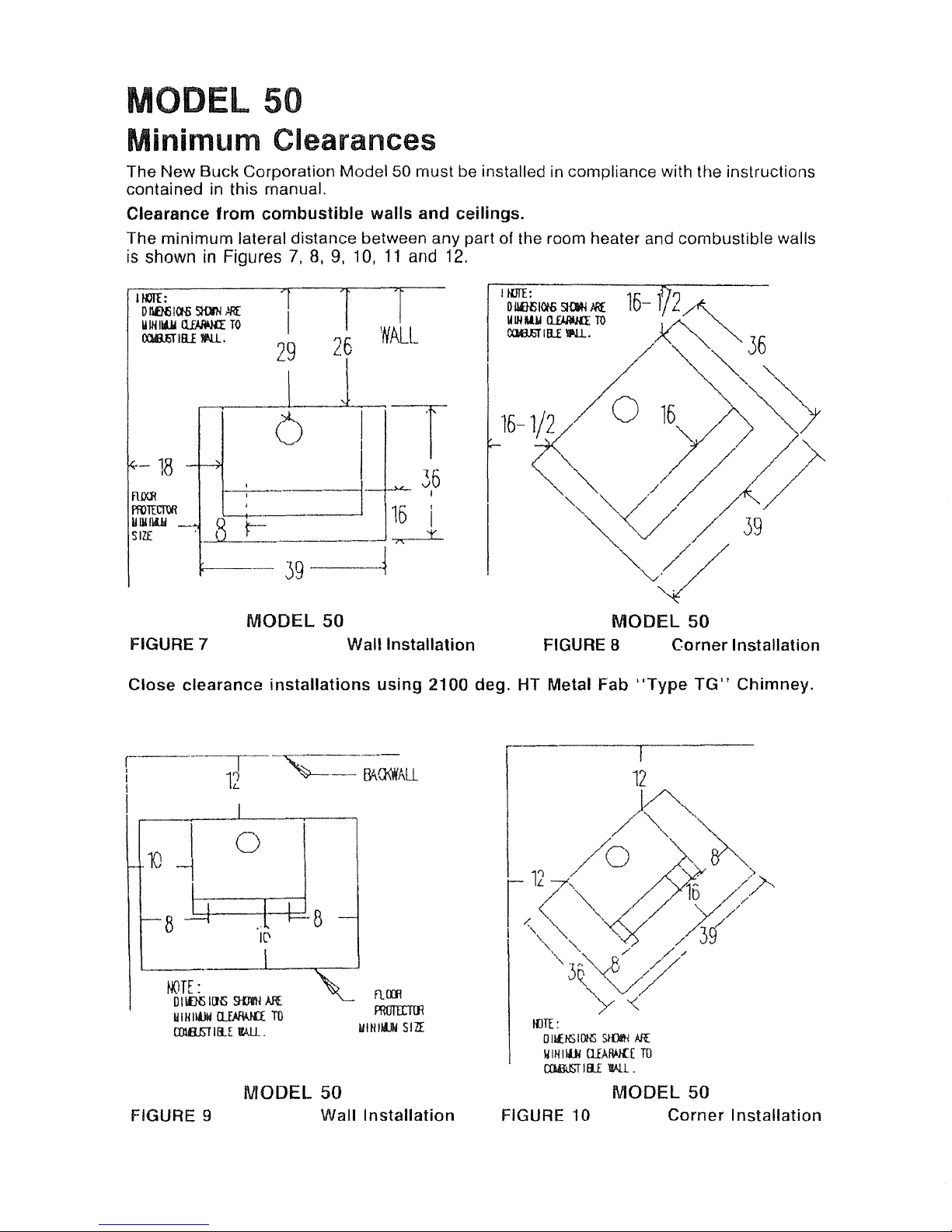
MODEL 50
Minimum Clearances
The
New
Buck
Corporation
Model
50 must be installed in compliance with the instructions
contained in this manual.
Clearance
from
combustible
walls and ceilings.
The
minimum
lateral distance between any part of the room heater and combustible walls
is
showninFigures7,8,9,10,
11
and
12.
26
I
29
\ ,
11mI:
o
IlofJfi
100>
SH)J'N
~
IlIN
II4.Ii
Q...EAAij{[
TO
lXlIUiT
tIlE
1IU.,
FIGURE 7
MODEL
50
Wall Installation
MODEL
50
FIGURE 8 Corner Installation
Close clearance
installations
using
2100 deg. HT Metal Fab
"Type
TG"
Chimney.
r-
1J
-~---
I
"---
~O<I¥All
I
I
I
10
I
0
-j
8
8
1(1
hQTE:
oI
~
Ilffi
SUllH
AI{
IIIHIltJII
lliM-Un
m
COlBETIIl.E
l(!li.
FIGURE 9
MODEL
50
Wall
Installation
I
12
~
1
"
/0
~~~
I
('
//)i~
/~/.
I
/''''''~
~
,'"
/
//
'"
3~A~
//
//
.
'V/
v
/ "
IllTE
:
o
lIENS
10l-lS
StIJA'tj
Aff.
IIIHIIOI
lliAfWlI
m
al4lUST
IIlE
TWL
MODEL 50
FIGURE
10
Corner
Installation
Page 16
 Loading...