

New Buck Corporation 60, 60ZC, 40, 25 Installation Manual
Gas-Fired
Vented Room Heaters
Models 60, 60ZC, 40 & 25
Installation Manual
New Buck Corporation
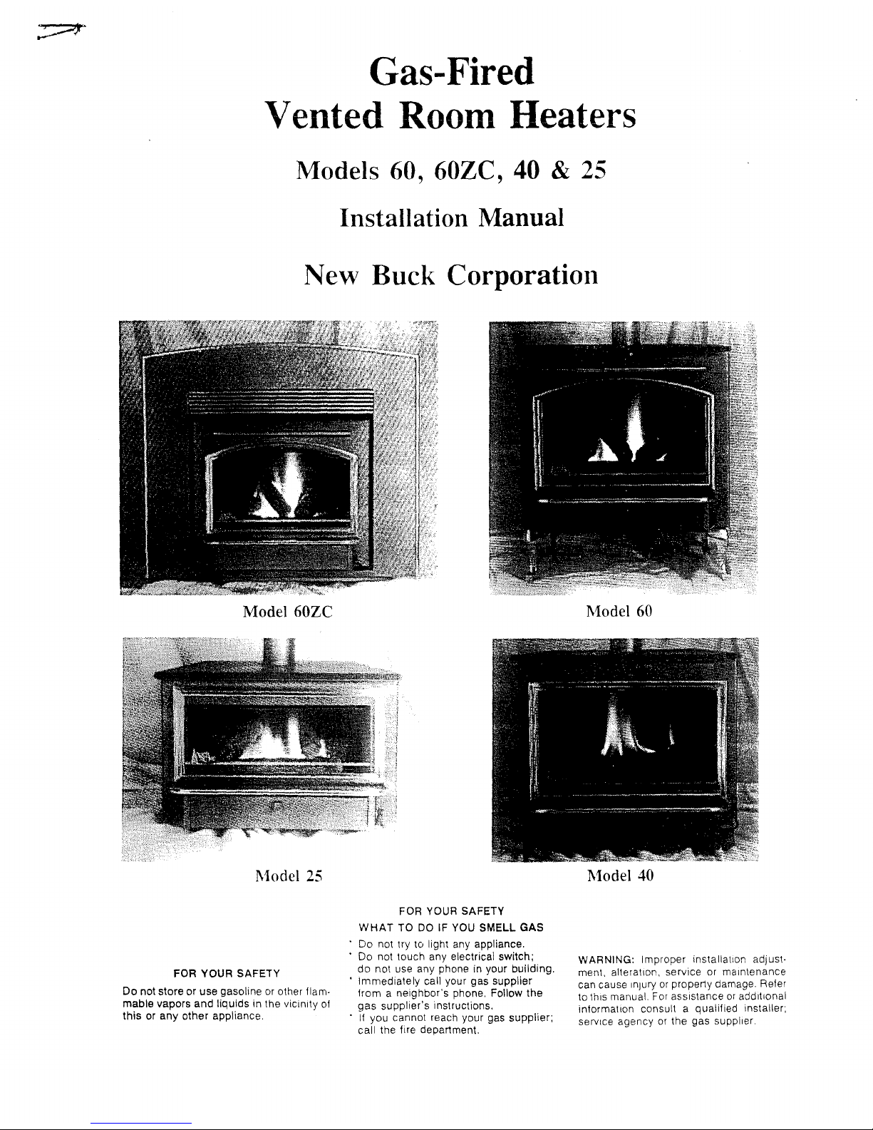
Model60ZC
Model
25
Model
60
Model 40
FOR YOUR SAFETY
Do
not store or use gasolineorother flam·
mabie vapors and liquids in the vicinity of
thisorany
other appliance.
FOR YOUR SAFETY
WHATTODOIFYOU
SMELL
GAS
Do not try to light any appliance.
Do not touch any electrical switch;
do
not use any phone in your building.
• Immediately call your gas supplier
from a neighbor's phone, Follow the
gas
supplier's instructions.
•
If
you cannot reach your gas supplier;
call the fire department.
WARNING: Improper installation adjust·
ment, alteration, service or
maintenance
can cause Injuryorproperty damage. Refer
to
this manual.
For
assistanceoradditional
information consult a qualified installer;
service agency
or
the gas supplier

INDEX
INSTALLATION
CAUTIONS 2
FREE
STANDING
INSTALLATIONS.................................
3
POSITIONING
THE
UNIT........................................
3
MINIMUM
CLEARANCES................
. . . . . . . . . . . . . . . . . . • . . . . .
..
3
CHIMNEY
INSTALLATION........................................
4
GLASS
REMOVAL...............................................
5
WIRING.
. . . . . . . . . . . . . . . . . . . . . . . . . . . . . . . . . . . . . . . . . . . . . . • . . • .
..
5
CONNECTING
GAS
LINE.........................................
6
MINIMUM/MAXIMUM GAS
SUPPLY
PRESSURE 6
WALL
SWITCH
INSTRUCTIONS....................................
6
LOG
INSTALLATION............................................
7
LIGHTING
AND
SHUTDOWN
7-10
ALCOVE
INSTALLATION........................................
11
PRE-FAB
FIREPLACE
INSERT
INSTRUCTIONS
12
MASONRY
INSERT
INSTALLATION
15
SAFETY.
. . . . . . . . . . . . . . . . . . . . . . . . . . . . . . . . . . . . . . . . . . . . . . . . . . . .
16
CLEANING
AND
MAINTENANCE
REQUIREMENTS
18
TROUBLE
SHOOTING.........................................
19-
2 0
PEPLACEMENT
PARTS........................................
21
MODEL
60
ZERO
CLEARANCE
INSTRUCTIONS
22-26
GAS
HEATER
MODELS
40,
60
& 25
INSTALLATION INSTRUCTIONS
IMPORTANT:
Read
this
manual
before
installing
and
using
this
gas
heater.
Installation
and/or
repair
of
this
unit
should
only
be
done
by
a
qualified
installer.
This
appliance
has
been
tested
to
and
complies
with
ANSI
Z21.11.1b
(1990).
Installation
must
conform
with
local
building
codes
or,
in
the
absence
of
local
building
codes,
with
national
fuel
gas
code,
ANSI
Z223.1-1988
NFPA
54
(88).
FOR
YOUR
SAFETY
WHAT
TO
DO
IF
YOU
SMELL
GAS
*
*
*
• *
*
*
Do
not
try
to
light
any
appliance
Do
not
touch
any
electrical
switch
Do
not
use
any
phone
in
your
building
Immediately
call
your
gas
supplier
from
a
neighbor's
phone.
Follow
the
gas
supplier's
instructions.
If
you
cannot
reach
your
gas
supplier,
call
the
fire
department
Do
not
store
or
use
gasoline
or
other
flammable
vapors
and
liquids
in
the
vicinity
of
this
or
any
other
appliance
WARNING:
Do
not
use
this
appliance
if
any
part
has
been
under
water.
Immediately
call
a
qualified
service
technician
to
inspect
the
appliance
and
to
replace
any
part
of
the
control
system
which
has
been
under
water.
WARNING:
Improper
installation,
adjustment,
alteration,
service
or
maintenance
can
cause
injury
or
property
damage.
For
assistance
or
additional
information
consult
a
qualified
installer,
service
agency
or
the
gas
supplier.
WARNING:
DO
NOT
REPLACE
THE
BURNER
UNIT
WITH
ANY
OTHER
SIZE
BURNER.
REPLACEMENT
WITH
AN
UNAUTHORIZED
BURNER
CAN
RESULT
IN TEMPERATURES
EXCEEDING
THE
LIMITS
FOR
THIS UNIT,
AND
VOID
YOUR
WARRANTY.
2

FREE
STANDING
INSTALLATION
A)
POSITION
THE
UNIT
1.
Determine
the
exact
position
of
your
gas
heater.
If
possible
place
the
heater
in
such
a
manner
that
the
piping
will
be
placed
between
two
wall
studs
so
additional
framing
is
not
necessary.
Also,
try
to
place
unit
where
flue
pipe
exit
is
between
two
ceiling
joist.
NOTE:
Maintain
minimum
clearances.
(See
Figure
1)
DO
NOT
allow
the
combustion
and
ventilation
air
to
be
obstructed.
Air
enters
at
the
bottom
of
these
units.
NOTE:
DUE
TO
HIGH TEMPERATURES, THESE UNITS
SHOULD
BE
LOCATED
OUT
OF
TRAFFIC
AREAS
AND
AWAY
FROM
FURNITURE
AND
DRAPERIES.
o
WALL
//
/3"
~3"
3"
//
,----------~
WALL/
/
o
WALL
4
11
-L..----
UN
=IT:-:F=RO=NT=------>
WALL
Figure
1
UNITFRONT
NOTE: When
the
appliance
is
installed
directly
on
carpeting,
tile
or
other
combustible
material,
the
appliance
shall
be
installed
on
a
listed
metal
panel
extending
the
full
width
and
depth
of
the
appliance.
WARNING:
"Operation
of
this
heater
when
not
connected
to
a
properly
installed
and
maintained
venting
system
or
tampering
with
the
vent
safety
shutoff
system,
can
result
in
carbon
monoxide
(co)
poisoning
and
possible
death."
3

B)
INSTALL
THE
CHIMNEY
SYSTEM:
WARNING:
This
gas
appliance
must
not
be
connected
to
a
chimney
flue
serving
another
type
of
appliance.
This
heater
must
be
properly
connected
to
a
venting
system.
Class
"B"
-
4"
flue
vent
vent
pipe
manufacturer's
for
proper
installation.
to
roof.
is
required
for
this
unit.
Follow
the
instruction
or
NFPA
54 (ANSI
Z223.1
1988)
Also
see
Figure
2
for
minimum
clearances
CAUTION:
The
installation
must
conform
to
local
codes.
In
the
absence
of
local
codes,
installation
must
conform
with
the
National
Fuel
Gas
Code
ANSI
Z223.1a-1988.
NOTE:
This
unit
is
equipped
with
a
safety
spill
switch.
This
switch
will
shut
off
the
unit
if
there
is
any
problem
with
the
chimney.
12'
_ LlSTED
CLASS
'E'
CHIMNEY
CAP
MIN,
l'
CLEARANCE
STANDOFF
SLEEVE
------------.'.r-,........".
__
FIRESTOP
__
4'
'B'
VENT
PIFE
CLASS
'B'
VALL
THIMBLE
1/2'
R1SE
PER
FOOT
-------
OF
LENGTH
-----.-+-'c-t-
Fifllre
2
4
HET
AL
FLASHIt~G
\,fOOD
CHA$E
C)
REMOVE
THE
GLASS
FRONT
1.
The
glass
front
is
attached
with
four
screws
set
into
key
slots,
cut
into
the
face.
2.
Push
up
on
the
entire
framework
approximately
1/4"
and
remove
by
pulling
outward.
3.
Set
glass
enclosure
aside
where
it
will
not
be
broken.
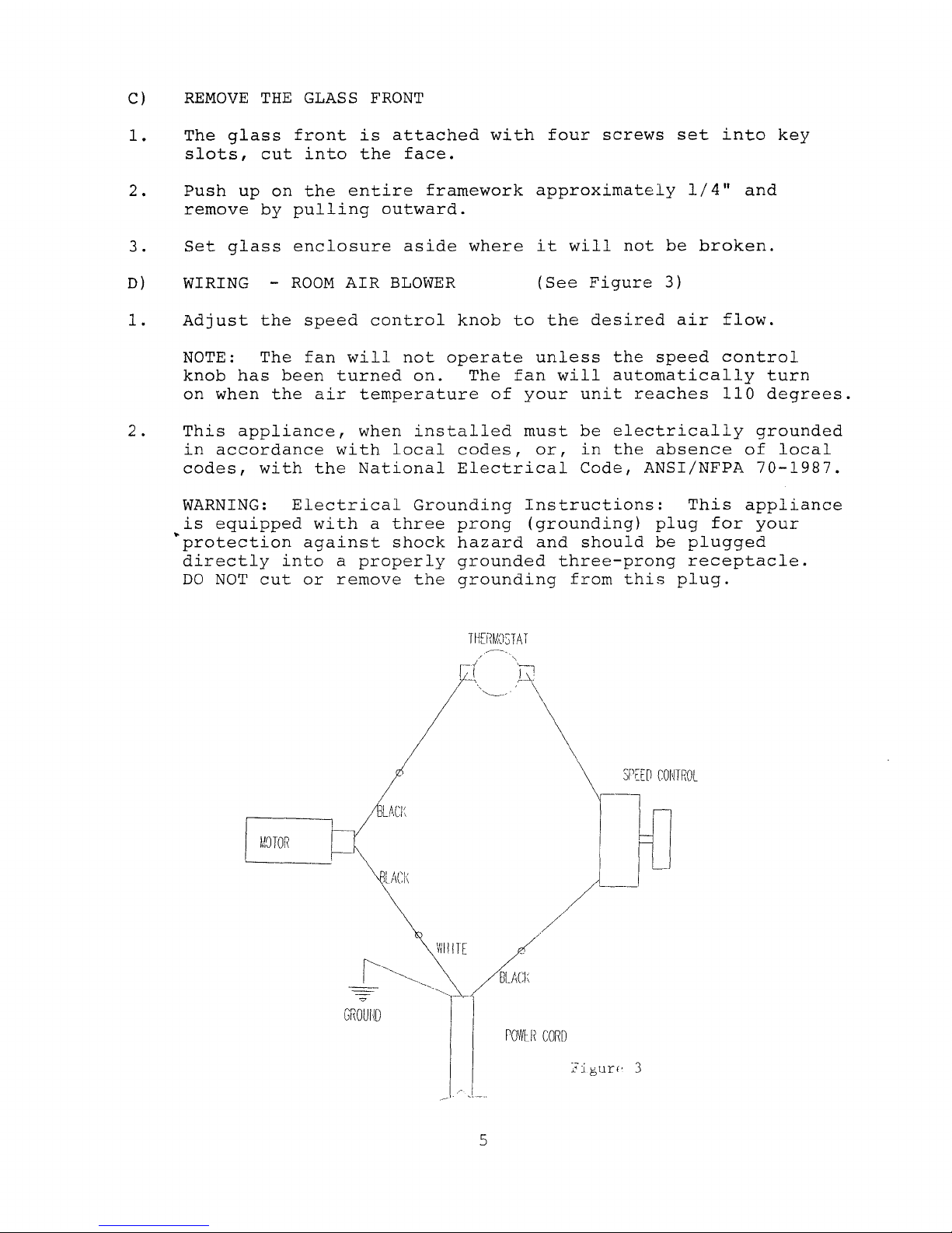
D)
WIRING -
ROOM
AIR
BLOWER
(See
Figure
3)
1.
Adjust
the
speed
control
knob
to
the
desired
air
flow.
NOTE:
The
fan
will
not
operate
unless
the
speed
control
knob
has
been
turned
on.
The
fan
will
automatically
turn
on
when
the
air
temperature
of
your
unit
reaches
110
degrees.
2.
This
appliance,
when
installed
must
be
electrically
grounded
in
accordance
with
local
codes,
or,
in
the
absence
of
local
codes,
with
the
National
Electrical
Code,
ANSI/NFPA
70-1987.
WARNING:
Electrical
Grounding
Instructions:
This
appliance
is
equipped
with
a
three
prong
(grounding)
plug
for
your
·protection
against
shock
hazard
and
should
be
plugged
directly
into
a
properly
grounded
three-prong
receptacle.
DO
NOT
cut
or
remove
the
grounding
from
this
plug.
THERMOSTAT
MOTOR
LACI;
POWU(
CORD
5
E)
CONNECT
THE
GAS
LINE
CAUTION:
Installation
of
the
gas
line
must
only
be
done
by
a
qualified
person
in
accordance
with
local
building
codes.
1.
Connect
gas
line.
An
accessible
shut
off
valve
must
be
installed
up
stream
from
the
unit.
NOTE:
DO
NOT
run
the
incoming
gas
line
in
a
manner
that
would
obstruct
the
operation
or
removal
of
the
fan.
NOTE:
The
minimum
inlet
gas
supply
pressure
is
4.0
inches
W.C.
The
maximum
inlet
gas
supply
pressure
is
10.5
inches
W.C.
2.
This
unit
is
designed
to
accept
either
a
3/8"
or
1/2"
gas
line
approved
for
gas
appliances.
Consult
local
building
codes
to
properly
size
the
gas
supply
line
leading
to
a
3/8"
reduction.
3.
A
gas
line
knockout
is
positioned
on
either
side
of
the
unit
for
gas
line
connection.
4.
Attach
proper
fittings
to
the
regulator
board
for
easier
installation.
5.
Complete
installation
of
the
gas
line.
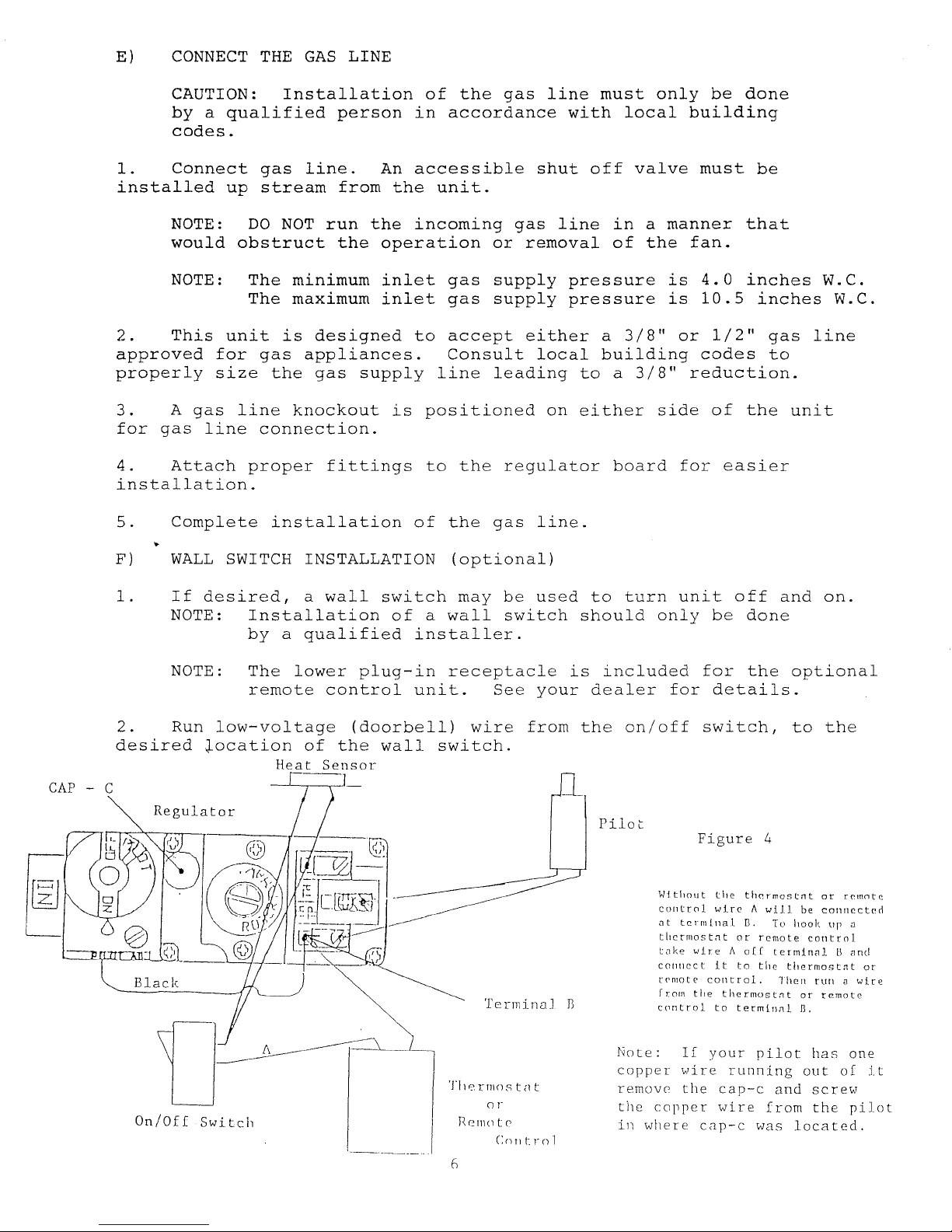
F)
WALL
SWITCH INSTALLATION
(optional)
1.
If
desired,
a
wall
switch
may
be
used
to
turn
unit
off
and
on.
NOTE:
Installation
of
a
wall
switch
should
only
be
done
by
a
qualified
installer.
NOTE:
The
lower
plug-in
receptacle
is
included
for
the
optional
remote
control
unit.
See
your
dealer
for
details.
2.
Run
low-voltage
(doorbell)
wire
from
the
on/off
switch,
to
the
desired
~ocation
of
the
wall
switch.
Heat
Sensor
CAP
- C
Black
On/Off
Switch
Terminal
J)
Tl1erT1lostnt
01-
HeT1loto
C()lltrol
Pilot
Figure
4
WitholIt
the
thermost<lt
or
remntr.
control
wireAwill
be
connected
at
termlnal
n.
To
hook
up
a
tllCrll10stllt
or
remote
control
take
wire
A
0((
terminal
U
and
conllect
it
to
the
thermostat
or
rpnlote
cOlltrol.
Then
run
a
wire
from
tIle
thermost.1t
or
remote
control
to
termini1l
n.
Note:
If
your
pilot
has
one
copper
wire
running
out
of
it
removo
the
cap-c
and
screw
the
copper
wire
from
the
pilot
in
where
C<1P-C
was
located.

G)
COMPLETE
THE
INSTALLATION
1.
Position
the
logs,
either
Model
40,
60
or
25
as
illustrated
below.
c
Model
60
Figure
5
2.
Replace
the
glass
enclosure.
H)
LIGHTING
AND
SHUTDOWN
NOTE:
Prior
to
lighting,
check
all
fittings
for
leakage.
This
is
accomplished
by
applying
soapy
water
on
all
connections
made.
If
there
is
any
leakage
bubbles
will
appear
at
the
point
of
connections.
If
bubbles
occur,
tighten
the
fittings
until
the
bubbles
no
longer
appear.
All
connections
made
at
the
factory
have
been
previously
tested.
NOTE:
The
appliance
and
its'
individual
shut
off
valve
must
be
disconnected
from
the
gas
supply
piping
system
during
any
pressure
testing
of
the
system
at
test
pressures
in
excess
of
1/2
psig
(3.5
kPa)
.
The
appliance
must
be
isolated
from
the
gas
supply
piping
system
by
closing
its
individual
manual
shut
off
valve
during
any
pressure
testing
of
the
gas
supply
piping
system
at
test
pressures
equal
to
or
less
than
1/2
psig
(3.
5kPa)
.
An
1/8"
NPT
plugged
tap
is
located
on
the
right
side
of
regulator,
immediately
upstream
of
the
gas
supply
connection
to
the
appliance.
This
is
used
for
test
gauge
connection.
7
 Loading...