

Page 1

SDI-TD-3GMX-5 / SDI-TD-3GDX-5
HD-TD-3GMX-2 / HD-TD-3GDX-2
2xHD-SDI or HD-SDI + 4xSD-SDI over 3GHD-SDI
Time Division Multiplexers / De-Multiplexers
User manual
Rev. F
Nevion
Nordre Kullerød 1
3241 Sandefjord
Norway
Tel: +47 33 48 99 99
nevion.com
Page 2
HD-TD-3GMX-2 / HD-TD-3GDX-2 and SDI-TD-3GMX-5 / SDI-TD-3GDX-5 Rev. F
Nevion Europe
P.O. Box 1020
3204 Sandefjord, Norway
Support phone 1: +47 33 48 99 97
Support phone 2: +47 90 60 99 99
Nevion USA
1600 Emerson Avenue
Oxnard, CA 93033, USA
Toll free North America: (866) 515-0811
Outside North America: +1 (805) 247-8560
E-mail: support@nevion.com
See http://www.nevion.com/support/ for service hours for customer support globally.
Rev.
Repl.
Date
Sign
Change description
F E 2013-09-10
JD
Removed line about future ASI support.
E D 2013-07-16
TB
Removed erroneous GPI information.
D 3 2013-01-08
TB
Added power consumption figure for product
variants with the optional DWDM module.
3 2 2011-11-22
AJM
Updated Table 4: Back plane connectivity.
2 1 2011-10-28
TB
Added DWDM in variants list, corrected variants
list. Added a DWDM related exception to the LED
table.
1 0 2011-10-19
AJM
Changed optical overload.
0 - 2011-05-09
SHH
First release
Nevion Support
Revision history
Current revision of this document is the uppermost in the table below.
nevion.com | 2
Page 3

HD-TD-3GMX-2 / HD-TD-3GDX-2 and SDI-TD-3GMX-5 / SDI-TD-3GDX-5 Rev. F
Contents
Revision history ........................................................................................................ 2
1 The multiplexer / de-multiplexer pair at a glance ................................................... 4
1.1 Product versions ........................................................................................................... 5
2 Multiplexer specifications ....................................................................................... 6
3 De-multiplexer specifications ................................................................................. 8
4 Description .......................................................................................................... 10
4.1 The HD-TD-3GMX-2 and HD-TD-3GDX-2 ....................................................................10
4.2 The SDI-TD-3GMX-5 and SDI-TD-3GDX-5 ..................................................................11
4.3 HD ancillary data limitations .........................................................................................11
5 Configuration and monitoring .............................................................................. 13
5.1 Configuration ................................................................................................................13
5.1.1 Configuring the multiplexers from Multicon GYDA .....................................................13
5.1.2 Configuring the de-multiplexers from Multicon GYDA ................................................17
5.1.3 Configuring the multiplexers with the DIP switches....................................................19
5.1.4 Configuring the de-multiplexers with the DIP switches ..............................................19
5.2 Monitoring ....................................................................................................................20
5.2.1 The information page for the multiplexer cards ..........................................................20
5.2.2 The information page for the de-multiplexer cards .....................................................22
6 Using the cards with the SDI-TD-MUX-4 and SDI-TD-DMUX-4 .......................... 25
7 Connections ........................................................................................................ 26
7.1 Power connections .......................................................................................................26
7.2 Backplane ....................................................................................................................26
7.2.1 GPI connections, RJ45 ..............................................................................................27
7.3 The main board ............................................................................................................27
8 Operation ............................................................................................................. 29
8.1 Front panel LED indicators ...........................................................................................29
8.2 RS422 commands ........................................................................................................31
8.2.1 FLP4.0 required commands, common for MUX and DMUX cards .............................31
8.2.2 Normal control blocks for the MUX cards ..................................................................32
8.2.3 Normal control blocks for the DMUX cards ................................................................33
9 Laser safety precautions ..................................................................................... 35
General environmental requirements for Nevion equipment .................................. 36
Product Warranty.................................................................................................... 37
Appendix A Materials declaration and recycling information .................................. 38
A.1 Materials declaration ....................................................................................................38
A.2 Recycling information ...................................................................................................38
nevion.com | 3
Page 4

HD-TD-3GMX-2 / HD-TD-3GDX-2 and SDI-TD-3GMX-5 / SDI-TD-3GDX-5 Rev. F
1 The multiplexer / de-multiplexer pair at a glance
The SDI-TD-3GMX-5 is a Flashlink time-division multiplexer (TDM) that either allows any
pair of supported HD-SDI or SD-SDI inputs or a single HD-SDI or SD-SDI input, plus up to
4 SD-SDI inputs to be transported over a single 3GHD-SDI link.
The SDI-TD-3GDX-5 is a Flashlink time division de-multiplexer that either recovers the 2
HD-SDI/SD-SDI streams or the single HD-SDI/SD-SDI stream plus 4xSD-SDI streams from
the 3GHD transport signal. The selection is automatic, based on what is detected in the
stream.
The HD-TD-3GMX-2 is a Flashlink time-division multiplexer (TDM) that allows any pair of
supported HD-SDI or SD-SDI inputs to be transported over a single 3GHD-SDI link.
The HD-TD-3GDX-2 is a Flashlink time division de-multiplexer that recovers the 2 HDSDI/SD-SDI streams from the 3GHD transport signal.
Other key features of the multiplexer / de-multiplexer pair include:
Supports all the most common video standards including SDTI.
Accepts any combination of synchronous or asynchronous HD-SDI 1485 Mbps or
SD-SDI 270 Mbps input formats, as long as the video standard is supported. Correct
video formats will be recovered at the de-multiplexer end.
Separate stream clock reference data for each channel is transferred for remote
clock regeneration. Correct clocks will be recovered at the de-multiplexer end.
Automatic input format detection for each channel.
All streams embedded in the 3GHD transport signal are completely independent. No
cross-contamination of the other stream when one input is lost.
Low latency.
Can be combined with SDI-TD-MUX-4 and SDI-TD-DMUX-4 modules to transport
up to 8 SD-SDI channels over one 3GHD link.
High performance optics for short and long haul applications available, including
CWDM and DWDM.
Optical and electrical 3GHD TDM outputs are available simultaneously from the
multiplexer cards, if purchased with an optional laser.
Change-over functionality between de-multiplexer electrical and optical inputs.
The transport signal is compliant with the SMPTE-425M Layer B standard and will
always be marked as 1080/30P. Standard 3GHD infrastructure can be used to
transport the multiplexed signal.
Multicon interface allows remote control, status monitoring, error reporting and
SNMP support.
The HD-TD-3GMX-2 and HD-TD-3GDX-2 can be field upgraded to the SDI-TD-
3GMX-5 and SDI-TD-3GDX-5 respectively if the need arises.
nevion.com | 4
Page 5

HD-TD-3GMX-2 / HD-TD-3GDX-2 and SDI-TD-3GMX-5 / SDI-TD-3GDX-5 Rev. F
SDI-TD-3GMX-5
5-input multiplexer over 3GHD-SDI with electrical
output, supporting transportation of 1xHD-SDI +
4xSD-SDI or 2xHD-SDI/SD-SDI.
SDI-TD-3GMX-5-13T, -5.0dBm
As SDI-TD-3GMX-5, with the addition of an optical
output based on a 1310nm, -5dBm transmitter.
SDI-TD-3GMX-5-C1xxx
As SDI-TD-3GMX-5, with the addition of an optical
CWDM output based on a 0dBm transmitter.
SDI-TD-3GMX-5-D15xx.xx, 0dBm
As SDI-TD-3GMX-5, with the addition of an optical
DWDM output based on a 0dBm module.
SDI-TD-3GMX-5-D15xx.xx, 5.0dBm
As SDI-TD-3GMX-5, with the addition of an optical
DWDM output based on a +5.0dBm module.
SDI-TD-3GDX-5
5-output 3GHD-SDI to HD-SDI/SD-SDI de-multiplexer
with electrical input.
SDI-TD-3GDX-5-R
5-output 3GHD-SDI to HD-SDI/SD-SDI de-multiplexer
with electrical input and a short haul optical receiver.
SDI-TD-3GDX-5-R-L
5-output 3GHD-SDI to HD-SDI/SD-SDI de-multiplexer
with electrical input and a high sensitivity long haul
optical receiver.
HD-TD-3GMX-2
2-input multiplexer over 3GHD-SDI with electrical
output, supporting transportation of 2x HD-SDI/SDSDI.
HD-TD-3GMX-2-13T, -5.0dBm
As HD-TD-3GMX-2, with the addition of an optical
output based on a 1310nm, -5dBm transmitter.
HD-TD-3GMX-2-C1xxx
As HD-TD-3GMX-2, with the addition of an optical
CWDM output based on a 0dBm transmitter.
HD-TD-3GMX-2-D15xx.xx, 0dBm
As HD-TD-3GMX-2, with the addition of an optical
DWDM output based on a 0dBm module.
HD-TD-3GMX-2-D15xx.xx, 5.0dBm
As HD-TD-3GMX-2, with the addition of an optical
DWDM output based on a +5.0dBm module.
HD-TD-3GDX-2
2-output 3GHD-SDI to HD-SDI/SD-SDI de-multiplexer
with electrical input.
HD-TD-3GDX-2-R
2-output 3GHD-SDI to HD-SDI/SD-SDI de-multiplexer
with electrical input and a short haul optical receiver.
HD-TD-3GDX-2-R-L
2-output 3GHD-SDI to HD-SDI/SD-SDI de-multiplexer
with electrical input and a high sensitivity long haul
optical receiver.
1.1 Product versions
nevion.com | 5
Page 6

HD-TD-3GMX-2 / HD-TD-3GDX-2 and SDI-TD-3GMX-5 / SDI-TD-3GDX-5 Rev. F
Number of inputs
2 independent HD-SDI/SD-SDI, 3 independent SD-SDI
Data rates
1485 Mbps / 270 Mbps
Equalization
Automatic up to 100 m Belden 1694A for SD/HD-SDI
Impedance
75 ohm
Return loss
HD/SD inputs: >15 dB upto 1485 MHz
SD only inputs: >15 dB upto 270 MHz
Connector
BNC
Output signal
3GHD-SDI according to SMPTE 425M Layer B, marked as
1080/30p
Data rate
2970 Mbps
Impedance
75 ohm
Return loss
>13 dB upto 1485 MHz, >10dB upto 2970MHz
Jitter (UI = Unit Interval)
Max. 0.2 UI
Peak to peak signal level
0.8 V ± 10%
Signal polarity
Non-inverting
Connector
BNC
Output signal
3GHD-SDI according to SMPTE 425M Layer B, marked as
1080/30p
Transmission circuit fiber
Single mode
Light source
FP / DFB laser
Optical power
-5 dBM @ 1310 nm (FP laser), 0 dBm CWDM (DFB laser),
0/+5dBm DWDM (DFB laser)
Optical centre wavelength
1310 nm
CWDM according to ITU-T G.694.2
DWDM according to ITU-T G.694.1 ch 20-59
Max. wavelength drift
13T: ±20 nm
CWDM: ±6 nm
DWDM: +/- 0.16 nm
Jitter (UI = Unit Interval)
Max. 0.2 UI
Connector return loss
better than 40 dB w/ SM fiber
Connector
SC/UPC
Temperature range
0 to +45 °C
Power consumption
+5 V / 5.0 W (7.0 W max with optional DWDM module), and
+15 V / 1.5 W
Control
RS-422, Multicon GYDA enabled, SNMP, DIP switch control
and LED status monitoring for manual use.
Electrical and optical delay
Less than 100 us (combined through MUX and DMUX)
In addition comes 5 us/km of fiber signal propagation time
2 Multiplexer specifications
Electrical inputs
Electrical output (standard)
Optical output (optional)
General
Latency
nevion.com | 6
Page 7

HD-TD-3GMX-2 / HD-TD-3GDX-2 and SDI-TD-3GMX-5 / SDI-TD-3GDX-5 Rev. F
SMPTE 125M-1995
Component Video Signal 4:2:2 — Bit-Parallel Digital
Interface
SMPTE 259M
SDTV1 Digital Signal/Data - Serial Digital Interface
SMPTE274M-2008
1920 x 1080 Image Sample Structure, Digital representation
and Digital Timing Reference Sequences for Multiple Picture
Rates
SMPTE 291M-2006
Ancillary data packet and space formatting
SMPTE 292-2008
1.5Gb/s signal/data serial interface
SMPTE 296m-2001
1280 × 720 Progressive Image Sample Structure - Analog
and Digital Representation and Analog Interface
SMPTE297-2006
Serial Digital Fiber Transmission System for SMPTE 259M,
SMPTE 344M, SMPTE 292 and SMPTE 424M Signals
SMPTE424m-2006
3Gb/s signal/data Serial interface
SMPTE425-2008
3GB/s Signal/Data, Serial Interface - Source Image Format
Mapping
SMPTE RP165
Error Detection Checkwords and Status Flags for Use in BitSerial Digital Interfaces for Television
Supported standards for electrical and optical ports
nevion.com | 7
Page 8

HD-TD-3GMX-2 / HD-TD-3GDX-2 and SDI-TD-3GMX-5 / SDI-TD-3GDX-5 Rev. F
Input signal
3GHD-SDI with a TDM payload
Sensitivity
Better than -28dB (option –R-L)
Better than -20 dBm (option –R)
Detector overload threshold
Min. -6 dBm (option –R-L)
Min. -5 dBm (option –R)
Detector damage threshold
> +1 dBm
Optical wavelength
1200 – 1620 nm
Transmission circuit fiber
Single Mode 9/125 µm
Connector return loss
better than 40 dB
Connector
SC/UPC
Output signal
3GHD-SDI with a TDM payload
Data rate
2970 Mbps
Equalization
Automatic up to 70 m Belden 1694A
Impedance
75 ohm
Return loss
>13 dB upto 1485 MHz, >10dB upto 2970MHz
Connector
BNC
Number of outputs
2 independent HD-SDI / SD-SDI, 3 independent SD-SDI
Data rate
1485 Mbps / 270 Mbps
Impedance
75 ohm
Return loss
HD/SD outputs: >15 dB upto 1485 MHz
SD only outputs: >15 dB upto 270 MHz
Jitter (UI = Unit Interval)
Max. 0.2 UI
Peak to peak signal level
0.8 V ± 10%
Signal polarity
Non-inverting
Connector
BNC
Temperature range
0 to +45 °C
Power consumption
+5 V / 4.5 W and +15 V /1.6 W
Control
RS-422, Multicon GYDA enabled, SNMP, DIP switch
control and LED status monitoring for manual use.
Electrical and optical delay
Less than 100 μs (combined through MUX and DMUX) In
addition comes 5 us/km of fiber signal propagation time
SMPTE 125M-1995
Component Video Signal 4:2:2 — Bit-Parallel Digital
Interface
SMPTE 259M
SDTV1 Digital Signal/Data - Serial Digital Interface
SMPTE274M-2008
1920 x 1080 Image Sample Structure, Digital representation
3 De-multiplexer specifications
Optical input
Electrical input
Electrical output
General
Latency
Supported standards for electrical and optical ports
nevion.com | 8
Page 9

HD-TD-3GMX-2 / HD-TD-3GDX-2 and SDI-TD-3GMX-5 / SDI-TD-3GDX-5 Rev. F
and Digital Timing Reference Sequences for Multiple Picture
Rates
SMPTE 291M-2006
Ancillary data packet and space formatting
SMPTE 292-2008
1.5Gb/s signal/data serial interface
SMPTE 296m-2001
1280 × 720 Progressive Image Sample Structure - Analog
and Digital Representation and Analog Interface
SMPTE297-2006
Serial Digital Fiber Transmission System for SMPTE 259M,
SMPTE 344M, SMPTE 292 and SMPTE 424M Signals
SMPTE424m-2006
3Gb/s signal/data Serial interface
SMPTE425-2008
3GB/s Signal/Data, Serial Interface - Source Image Format
Mapping
SMPTE RP165
Error Detection Checkwords and Status Flags for Use in BitSerial Digital Interfaces for Television
nevion.com | 9
Page 10
HD-TD-3GMX-2 / HD-TD-3GDX-2 and SDI-TD-3GMX-5 / SDI-TD-3GDX-5 Rev. F
EQ
HD/SD
input 1
EQ
Reclocker
Reclocker
Remapper
3G Frame
Generator
Remapper
3G Time
Division
Multiplexer
Optical Transmitter
HD-TD-3GMX-2
Microcontroller
Remote
Control
Electrical Transmitter
Optical
Fiber
3G El.
Transp. Out
3G Clock
HD/SD
input 2
3G Opt.
Transp. Out
3G Opt.
Transp.
In
Reclocker
HD/SD
3G Time
Division
Demultiplexer
Optical Receiver
HD-TD-3GDX-2
Microcontroller
Remote
Control
Electrical Receiver
Optical
Fiber
CLK
regen.
3G El.
Transp.
In
HD/SD
output 1
EQ
HD/SD
HD/SD gen.
HD/SD gen.
CLK
Regen.
HD/SD
output 2
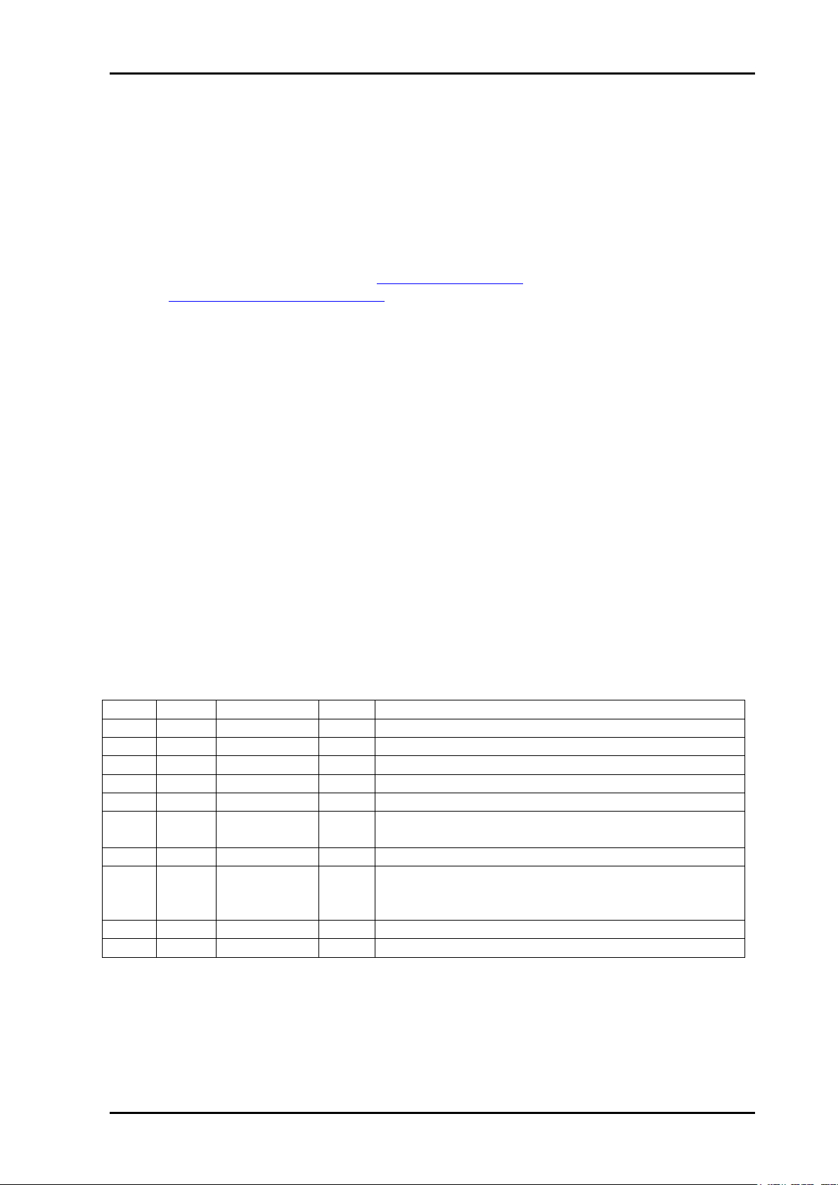
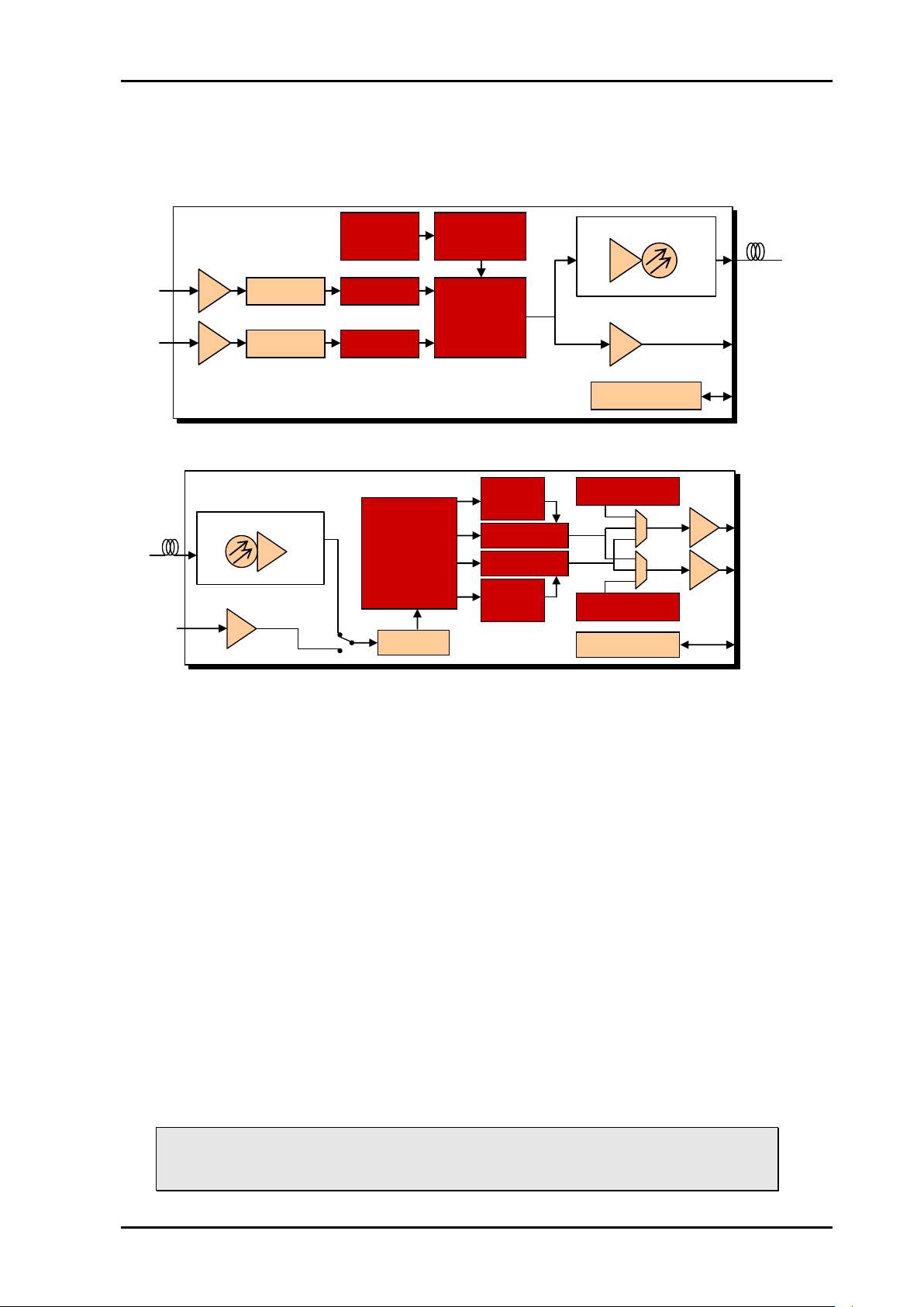
4 Description
4.1 The HD-TD-3GMX-2 and HD-TD-3GDX-2
Figure 1: Logical building blocks for the HD-TD-3GMX-2(-T)
Figure 2: Logical building blocks for the HD-TD-3GDX-2(-R)
The HD-TD-3GMX-2 board embeds up to two independent HD or SD video streams in one
output 3G stream. After the two HD or SD streams have been remapped, to avoid synchword conflicts with the transport stream frame, they are embedded in a 2.97 Gbps (3GHD)
stream in a proprietary protocol which is still compliant to the SMPTE 424-2006 and
SMPTE 425-2006 Level B standards. In order to reduce latency, the streams are
embedded asynchronously to each other and to the transport stream. The combined
latency of the HD-TD-3GMX-2 and HD-TD-3GDX-2 boards is always well below 100µs.
If the two HD streams were fully synchronous when entering the HD-TD-3GMX board, they
can have individual phase shifts of several samples after being demultiplexed at the HDTD-3GDX-2 end, but the clock frequencies will be the same as soon as the system has
stabilized (after a few seconds).
After demultiplexing in the HD-TD-3GDX-2 board, the data structure that was remapped on
the sender side will be restored and the data rate (pixel clock) will also be restored to
exactly the same rate as it was received on the HD-TD-3GMX-2 board.
The 3G signal is seen and transported as a standard 3G-SDI Level B (1080/30p) video by
external equipment. No other format can be set at the sender side of the link and no other
format will be accepted at the receiver side of the link. An HD-TD-3GDX-2(-R) or an SDIHD-3GDX(-R) board is required to reconstruct the two HD signals from the 3GHD at the
receiving end.
Note that frame synchronization or switching of the 3G transport signal should
be avoided, as switching or repeated/deleted frames will cause severe signal
failures in the recovered streams at the receiving end of the link.
nevion.com | 10
Page 11

HD-TD-3GMX-2 / HD-TD-3GDX-2 and SDI-TD-3GMX-5 / SDI-TD-3GDX-5 Rev. F
The HD-TD-3GMX-2 can receive any combination of two HD or SD video standards,
synchronous or asynchronous. The HD-TD-3GMX-2 embeds timing information that the
HD-TD-3DX-2 uses to regenerate the HD or SD signals with the same clock frequency as
the original inputs. The two signals are treated as two completely independent streams,
which means that there will be no cross-contamination of the other stream when one input
goes missing or has inherent errors.
The output from the HD-TD-3GMX-2 module is either electrical 3G-SDI according to the
SMPTE 425M standard, or if an optional laser module is added, simultaneous electrical and
optical 3GHD-SDI according to SMPTE 297-2006
If the customer has purchased an optional long haul or short haul receiver module for the
DMUX side (in which case the DMUX module will have an “R-L” or “-R” appended to its
name), there will be an option available to select either input manually, or to select between
them automatically.
4.2 The SDI-TD-3GMX-5 and SDI-TD-3GDX-5
The SDI-TD-3GMX-5 has two distinct modes of operation, set by the user: Either the same
two-input mode described above for the HD-TD-3GMX-2 / HD-TD-3GDX-2, or a mode with
up to five inputs, where only the first one can be HD-SDI. The latter mode is really the same
as the first, but with the addition of a 4xSD-to-1xHD software module from the SDI-TDMUX-4. This means that the HD stream normally coming straight from input 2, will now be
replaced with a multiplex of four SD-SDI inputs. This in turn means that input 2 can only
handle SD-SDI input signals in this mode, not HD-SDI. The user selection of the two modes
will prevent the possibility of overflowing the 3GHD-SDI carrier stream.
On the de-multiplexer side of the 3G transport link, the card will be able to read control
words embedded in the transport signal to determine which mode it should operate in. No
user control is necessary on the de-multiplexer side. The SDI-TD-3GDX-5 fully supports
input from both the SDI-TD-3GMX-5 and the HD-TD-3GMX-2, whereas the HD-TD-3GDX-2
will only be able to recover the signals for outputs 1 and 2 if fed a signal from an SDI-HD3GMX-5.
4.3 HD ancillary data limitations
Because the total usable transport bandwidth in the 3G output of the multiplexer is slightly
less than that of two full HD streams, a small number of samples must be dropped from the
incoming horizontal blanking intervals. The active picture will never be affected.
The number of samples dropped varies depending on the HD format as shown in Table 1.
Samples will be removed from the tail end of the HANC, following a left-alignment of all
valid packets. Given typical HANC payload size, such as required to carry AES audio, the
sample deletion will have no impact as it will occur entirely in unused samples.
In the case of an unusually full HANC, such that sample deletion would result in a
fragmented HANC packet, the remaining fragment will be deleted to maintain SMPTE
compliance.
HANC data that are not contained within a valid SMPTE 291M packet are not guaranteed to
be transported, and may appear as null or ’black’ values when de-multiplexed.
There are no limitations to the active video area portion of the HD signal to be
transferred – this will always be restored to its original content at the receiving
end of the link, as long as it is a valid video signal according to applicable
SMPTE standards.
nevion.com | 11
Page 12

HD-TD-3GMX-2 / HD-TD-3GDX-2 and SDI-TD-3GMX-5 / SDI-TD-3GDX-5 Rev. F
Standard
Active video area
HANC
words
per line
HANC
words
deleted
HANC
%
deleted,
Supporte
d in first
release
260M
(HD)
1920x1035/60 (2:1)
280
18/16
6.43
YES
259M
(HD)
1920x1080/50 (2:1)
456
21
4.61
YES
274M
(HD)
1920x1080/60 (2:1)
1920x1080/50 (2:1)
1920x1080/30 (1:1)
1920x1080/25 (1:1)
1920x1080/24 (1:1)
1920x1080/24 (PsF)
1920x1080/25 (1:1) 1920x1080/25 (PsF) EM
1920x1080/24 (1:1) 1920x1080/24 (PsF) EM
280
720
280
720
830
830
336
336
350
350
18/16
24
18/16
24
25/22
24/22
24
24
25/22
25/22
6.43
3.33
6.43
3.33
3.01
2.89
7.14
7.14
7.14
7.14
YES
YES
YES
YES
Pull-down
Pull-down
YES
YES
YES
YES
296M
(HD)
1280x720/30 (1:1)
1280x720/30 (1:1) EM
1280x720/50 (1:1)
1280x720/50 (1:1) EM
1280x720/25 (1:1)
1280x720/25 (1:1) EM
1280x720/24 (1:1)
1280x720/24 (1:1) EM
1280x720/60 (1:1)
1280x720/60 (1:1) EM
2020
420
700
252
2680
504
2845
525
370
210
32/27
32/27
16
16
39
39
41/39
41/39
12/10
12/10
1.58
7.62
2.29
6.35
1.46
7.74
1.44
7.81
3.24
5.71
Not p-d
Not p-d
YES
YES
NO
NO
NO
NO
YES
YES
125M
(SD)
1440x487/60 (2:1)
1440x507/60 (2:1)
525-line 487 generic
525-line 507 generic
276
276
276
276
0
0
0
0
0
0
0
0
YES
YES
YES
YES
ITU-R
BT.656
(SD)
1440x576/50 (2:1)
288
0 0 YES
625-line generic
288
0 0 YES
nevion.com | 12
Table 1: Supported video standards and HANC deletion rate
Page 13

HD-TD-3GMX-2 / HD-TD-3GDX-2 and SDI-TD-3GMX-5 / SDI-TD-3GDX-5 Rev. F
5 Configuration and monitoring
Both multiplexer and de-multiplexer cards are self-configuring in the sense that they will
start working according to default factory settings once power and input signals are applied.
HD-SDI or SD-SDI video standards will be detected and handled automatically.
5.1 Configuration
Configuration parameters can be changed in two ways: via changes to the DIP switches or
via the system controller Multicon GYDA. The lower DIP switch of the module is labeled
OVR. If this DIP is set to the ON position, the module will not accept commands from the
Multicon system controller, but will instead be controlled entirely by the position of the rest
of the DIP switches. Multicon GYDA will however be able to monitor the module and
retrieve the current configuration (this will be stored to enable hot-swap functionality with
another module under Multicon control). Conversely, if the OVR switch it is set to the OFF
position, the other DIPs are disregarded altogether and the module is under full Multicon
GYDA control. As delivered from the factory, all DIPs should be in the Off position. The
module will then be under Multicon GYDA control.
5.1.1 Configuring the multiplexers from Multicon GYDA
The HD-TD-3GMX-2 product contains a subset of the features found in the SDI-TD-3GMX-
5. The description below contains blocks that will only be found on the full featured product,
the SDI-TD-3GMX-5. The picture of the HD-TD-3GMX-2 configuration page is provided for
reference, see Figure 4.
Starting from the top of the page on the SDI-TD-3GMX, the following things can be
set/adjusted:
Card label: This field enables the user to set a name for each module (Actually, it’s the slot
in the frame, as the label will persist even if the card/backplane combination is replaced by
a completely different module). The name will show up above the card type on the info
page and on the configuration page, and it will also be shown as a mouse-over text when
the mouse cursor is held over the card’s icon in the pictured rack.
Locate card: Flashes the 4 LEDs on the front of the module at about 0.5 Hz for the number
of seconds the user specifies. This is intended to help find a card quickly in a large setup.
Firmware upgrade: The firmware for the onboard microcontroller and the FPGA can both
be upgraded, if needed. This red line only shows up if the Multicon GYDA system controller
has found a folder containing Flashlink firmware files. Contact Nevion Support if you need
an updated firmware.
Mode of operation: (Stored setting) The multiplexer can work in two distinct ways. It can
simply pack two HDs into one 3G stream, or it can pack 4 SDs into one HD before packing
the resulting HD with another HD from input 1. In the first case, the 2 HDs can each be
replaced with a single SD, but still only transport 2 channels over the 3G transport stream.
This will be handled automatically. In the second case, the HD on input 1 can be replaced
with an SD signal. This will also be handled automatically. The other 4 inputs will only
accept SD, and any HD signal on these inputs will simply be ignored.
The reason for splitting the operation into two modes can be seen when considering what
would happen when the card was fed 2 HDs and 3 SDs simultaneously. It would obviously
not be possible to transport all these signals over one 3G stream, so something has to be
given priority over the other inputs. The key is really whether input 2 is HD or SD, so if this
toggled between HD and SD, it would not only mean that one channel was unstable, it
would also affect whether inputs 3-5 would be transported or not. Hence the user is made
to make the choice. A corner case is when the mode is set to be HD/SD+4xSD and inputs
3-5 have no signal at all. In that case it is possible to transport an HD from input 2 (and it
nevion.com | 13
Page 14

HD-TD-3GMX-2 / HD-TD-3GDX-2 and SDI-TD-3GMX-5 / SDI-TD-3GDX-5 Rev. F
will be!), but it is a fragile state, as it will immediately be replaced with one or more SDs as
soon they’re detected on inputs 3-5.
Input integrity 1…5: (Stored setting) The user can select which errors should be counted
and which can be ignored. The CCS and YCS count settings work as a pair, meaning that
both will either be counted or both will be ignored. If the user makes a change to one of
these bits, the module assumes that the new setting should be applied to both bits. The
web page will always be updated to show the actual setting. The CCRC and YCRC error
bits also work as a pair.
The available error bits are as follows:
EAV – End of active video error
SAV – Start of active video error
LNUM – Line numbering error (HD only)
YCRC – Luma CRC error (HD only)
CCRC – Chroma CRC error (HD only)
YCS – Luma checksum error
CCS – Chroma checksum error
LOCK – Lock error
AP-CRC – Active picture CRC error (SD only)
FF-CRC – Full frame CRC error (SD only)
VS – Video standard error
Inputs 3-5, which are SD only, will not have LNUM, YCRC or CCRC errors available, since
these only have meaning for HD.
Laser: (Stored setting) The only setting available for the laser is power On or Off. All other
settings should already be done at the factory.
The laser module is optional. Boards with factory mounted laser will have “-T” appended to
the module’s name, and only they will display the laser block in the graphical user interface.
nevion.com | 14
Page 15

HD-TD-3GMX-2 / HD-TD-3GDX-2 and SDI-TD-3GMX-5 / SDI-TD-3GDX-5 Rev. F
Figure 3: The SDI-TD-3GMX-5 configuration page in Multicon GYDA.
nevion.com | 15
Page 16

HD-TD-3GMX-2 / HD-TD-3GDX-2 and SDI-TD-3GMX-5 / SDI-TD-3GDX-5 Rev. F
Figure 4: The HD-TD-3GMX-2 configuration page in Multicon GYDA.
nevion.com | 16
Page 17

HD-TD-3GMX-2 / HD-TD-3GDX-2 and SDI-TD-3GMX-5 / SDI-TD-3GDX-5 Rev. F
5.1.2 Configuring the de-multiplexers from Multicon GYDA
Figure 5: The SDI-TD-3GDX-5 configuration page in Multicon GYDA.
Starting from the top of the page, the following things can be set/adjusted:
Card label: See multiplexer description.
Locate card: See multiplexer description.
Firmware upgrade: See multiplexer description.
Input select: (Stored setting, only available when an optional optical input is installed). This
control is only available for boards with the optional optical input. Here the user can select
to force the input to be taken from either the electrical or the optical input, or allow the card
to automatically select between them.
In manual mode there is no fallback to the other input available at all. In auto mode, there’s
always a fallback to the other input available, the user only has to select which input is
considered the main input. The other is considered the backup.
The input selector is always latching. This means that if the input selector has (for some
reason) switched away from main to the backup, the selector will continue to stay in this
position until either the user selects to push the latch reset button, or the backup disappears
(at which point the logic will start to look for a valid input on either of the two inputs, but
starting with the main input).
Through the “hold time” and the “latch time” the user can select how long the module will
cling on to a lost signal and hope that it will reappear, and how long a signal must be
present before it is considered valid and stable, respectively.
nevion.com | 17
Page 18

HD-TD-3GMX-2 / HD-TD-3GDX-2 and SDI-TD-3GMX-5 / SDI-TD-3GDX-5 Rev. F
Integrity of 3G TDM input: (Stored setting) Sets the maximum error rate or the maximum
number of errors that can be present before Multicon GYDA sets off an alarm. Also sets
which types of errors should be counted and which should be ignored. See input integrity in
the multiplexer section for a description of the error bits.
Figure 6: The HD-TD-3GDX-2 configuration page in Multicon GYDA.
nevion.com | 18
Page 19

HD-TD-3GMX-2 / HD-TD-3GDX-2 and SDI-TD-3GMX-5 / SDI-TD-3GDX-5 Rev. F
Switch #
Function name
Function of DIPs
Comment
1
Laser enable
Off: Laser is turned off
On: Laser is turned on
Has no effect without
mounted laser module
(optional).
2
Operating mode
Off: 2xHD-SDI
On: 1xHD-SDI + 4xSD-SDI
If the card is a HD-TD3GMX-2(-T), this DIP will
have no effect.
3-6
---
Reserved
7
Factory reset
Off: Normal operation
On: Reset
This DIP is only read at
power up. See box below
for full explanation of the
factory reset function.
8
OVR
Off: Multicon GYDA mode
On: Manual mode
This DIP is only read at
power up.
OVR is short term for
Multicon GYDA override.
Switch #
Function
name
Function of DIPs
Comment
OPT/EL
Input priority
Off: The optical input has
priority over the electrical input
On: The electrical input has
priority over the optical input.
Has no effect without
mounted pin diode
module (optional).
AUTO/MAN
Input mode
Off: Auto
On: Manual
Has no effect without
mounted pin diode
module (optional).
2 unmarked
---
Reserved
1-6
---
Reserved
7
Factory reset
Off: Normal operation
On: Reset
This DIP is only read at
power up. See box below
for full explanation of the
factory reset function.
OVR
Control mode
Off: Multicon GYDA mode
On: Manual mode
This DIP is only read at
power up.
OVR is short term for
Multicon GYDA override.
5.1.3 Configuring the multiplexers with the DIP switches
Table 2: MUX DIP switch functions
5.1.4 Configuring the de-multiplexers with the DIP switches
None of the other DIP switches will be read unless the Control mode switch
(marked ‘OVR’) is in the Manual mode position (marked ‘On’).
A factory reset is a 3 step process:
* Set Factory reset DIP to the ‘On’ position and boot the card (The Control
mode must also be set to Manual mode).
* Remove power and set the reset switch back to normal position (Off)
* Power up the card as normal.
nevion.com | 19
Table 3: DMUX DIP switch functions
Page 20

HD-TD-3GMX-2 / HD-TD-3GDX-2 and SDI-TD-3GMX-5 / SDI-TD-3GDX-5 Rev. F
The operation of the card will immediately reflect the freshly loaded default settings.
However, the card must be kept powered for at least 10 seconds to ensure that these
settings are stored locally to be retrieved again at the next start-up. The card’s operational
environment must also be kept static during those 10 seconds (i.e. no change in incoming
video standards, no commands issued). Failing to meet these requirements could result in
an incomplete reset and require the user to restart the factory reset sequence.
5.2 Monitoring
5.2.1 The information page for the multiplexer cards
The information page shows a dynamic block diagram of the board and some additional
information in text form. The block diagram updates with the board status, showing missing
signals (by red crosses over the appropriate signal lines).
The text table on the information page gives additional information not easily conveyed in a
graphical manner.
From the text table, we can read the following: Both cable equalizers are enabled
(“Normal”), as opposed to “Bypassed”. None of the two reclockers has been able to lock to
a legal input. That the reclockers are unlocked can also be seem from the two red crosses
over the signal lines to the right of the reclocker boxes. When the reclockers are locked, the
bit rate will be indicated.
The error counter has found no errors for input 1 or 2 (at least not errors of the types that
are set be counted). We can also tell that the voltages are reasonably close to their nominal
values.
If this were a board with the laser option, the table would display an additional line like this:
Here we can see that the laser is powered and what kind of laser it is (wavelength, power
and type).
nevion.com | 20
Page 21

HD-TD-3GMX-2 / HD-TD-3GDX-2 and SDI-TD-3GMX-5 / SDI-TD-3GDX-5 Rev. F
Figure 7: Multicon GYDA presentation of rack with an HD-TD-3GMX-2module in position 2 and
an HD-TD-3GDX-2 in position 6.
nevion.com | 21
Page 22

HD-TD-3GMX-2 / HD-TD-3GDX-2 and SDI-TD-3GMX-5 / SDI-TD-3GDX-5 Rev. F
Figure 8: The MUX info page in Multicon GYDA.
5.2.2 The information page for the de-multiplexer cards
From the text table, we can read the following: The electrical input has been manually
selected. This (and the name of the module) also indicates that this board has the optional
optical input installed. No carrier is detected on the optical input.
The error counter has found no errors for the HD input (at least not errors of the types that
should be counted). We can also see that the voltages are reasonably close to their
nominal values (It is quite normal for the 5V supply to be 0.1V – 0.2V under its nominal
value).
nevion.com | 22
Page 23

HD-TD-3GMX-2 / HD-TD-3GDX-2 and SDI-TD-3GMX-5 / SDI-TD-3GDX-5 Rev. F
Figure 9: The DMUX info page in Multicon GYDA.
nevion.com | 23
Page 24

HD-TD-3GMX-2 / HD-TD-3GDX-2 and SDI-TD-3GMX-5 / SDI-TD-3GDX-5 Rev. F
Figure 10 DMUX info page in Multicon GYDA.
nevion.com | 24
Page 25

HD-TD-3GMX-2 / HD-TD-3GDX-2 and SDI-TD-3GMX-5 / SDI-TD-3GDX-5 Rev. F
6 Using the cards with the SDI-TD-MUX-4 and SDI-TDDMUX-4
The SDI-TD-MUX-4 can be used to multiplex 4 SD-SDI signals into a single HD-SDI. This
HD-SDI signal can in turn be used as input to the HD-TD-3GMX-2 or the SDI-TD-3GMX-5.
This means that is possible to embed up to eight SD-SDI signals on one 3G transport signal
with the use of either two SDI-TD-MUX4 + one HD-TD-3GMX-2 or one SDI-TD-MUX-4 +
one SDI-TD-3GMX-5. In addition, one SDI-TD-MUX4 + one HD-TD-3GMX-2 can effectively
be used together as one SDI-TD-3GMX-5, but at a slight penalty in the power consumption
and by using two rack slots instead of one.
The de-multiplexer side should normally be a mirror of the multiplexer setup. Although the
SDI-TD-DMUX-4 (and indeed the SDI-TD-MUX-4) has built-in matrices for routing
(‘shuffling’) the four SD-SDIs, it’s not possible to do any routing on the HD-SDI level.
nevion.com | 25
Page 26

HD-TD-3GMX-2 / HD-TD-3GDX-2 and SDI-TD-3GMX-5 / SDI-TD-3GDX-5 Rev. F
7 Connections
7.1 Power connections
Power is applied to the board via the backplane board, which in turn is plugged into the
power distribution bus in the Flashlink rack.
The HD-TD-3GMX-2 and SDI-TD-3GMX-5 boards both consume 5.0 W of power from the
+5 V supply and 1.5 W of power from the +15 V supply.
The HD-TD-3GDX-2 and SDI-TD-3GDX-5 boards both consume 3.7 W of power from the
+5 V supply and 1.7 W of power from the +15 V supply.
For all boards, this means that some power supplies will limit the number of
cards per frame to less than 10 (a fully populated frame). Check the power
ratings of the supply you plan to use!
7.2 Backplane
All cards mentioned in this manual use the same backplane. The direction of each BNC
port will depend on whether it is used with a multiplexer or a de-multiplexer board.
Table below shows the signal directions for the SDI-TD-3GMX-5 board, with the directions
for the SDI-TD-3GDX-5 in parentheses.
The GPI I/Os consists of alarm signals for driving external alarm devices and one input to
disable the laser output for the SDI-TD-3GMX-5/HD-TD-3GMX-2. See chapter 7.2.1.
Figure 11: The backplane, common for all cards mentioned in this manual.
nevion.com | 26
Page 27

HD-TD-3GMX-2 / HD-TD-3GDX-2 and SDI-TD-3GMX-5 / SDI-TD-3GDX-5 Rev. F
Name
Description
Connector Type
MUX/DEMUX
Output (Input) for 2970 Mbps 3GHD-SDI.
BNC
OPT
Optical output (input) for 2970 Mbps HD-SDI
(optional).
SC/UPC
1
Input (Output) for 1485 Mbps HD-SDI or 270 Mbps
SD-SDI.
BNC
2
Input (Output) for 1485 Mbps HD-SDI or 270 Mbps
SD-SDI.
BNC
3 (SD)
Input (Output) for 270 Mbps SD-SDI.
BNC
4 (SD)
Input (Output) for 270 Mbps SD-SDI.
BNC
5 (SD)
Input (Output) for 270 Mbps SD-SDI.
BNC
GPI I/O
General Purpose Interface.
RJ-45
Pin number
Multiplexer functionality
De-multiplexer functionality
1
Card OK.
This pin essentially follows the card’s status LED: When the LED is green, the pin
will indicate card OK. The pin will indicate NOT OK when the LED is yellow, that is
when the FPGA is being loaded.
2
Input 1 present
Output 1 present
3
Input 2 present
Output 2 present
4
Input 3 present
Output 3 present
5
Input 4 present
Output 4 present
6
Input 5 present
Output 5 present
7
Output OK.
This pin follows the output LED: It will
indicate OK when the output LED is
green, which is when output is present
and the laser not faulty.
Input OK.
This pin follows the LOS LED: It will
indicate OK when the LOS LED is
green, which is when input is present
and taken from the main input.
8
Ground (GND)
The following connectors are available:
Table 4: Back plane connectivity
7.2.1 GPI connections, RJ45
Figure 12: Pin layout
Table 5: GPI pin-out
The polarity of the GPI pins is such that OK/present is indicated by a leading transistor
connection to ground. Conversely, an error is indicated by high impedance to ground.
7.3 The main board
There are also a number of connectors on the board itself. None of these are intended for
the end-user.
nevion.com | 27
Page 28

HD-TD-3GMX-2 / HD-TD-3GDX-2 and SDI-TD-3GMX-5 / SDI-TD-3GDX-5 Rev. F
The rear end of the boards (with the connector that mates to the backplane) is towards the
right side of the board. The boards must be mounted in a Flashlink FR-2RU-10-2 frame with
dedicated backplanes. Avoid inserting the HD-TD-3GMX-2 or the HD-TD-3GDX-2 board
into a non-compatible backplane, as this may cause electrical and/or mechanical damage
to the main boards and/or the backplane.
Figure 13: MUX main board overview
Figure 14: DMUX main board overview
nevion.com | 28
Page 29

HD-TD-3GMX-2 / HD-TD-3GDX-2 and SDI-TD-3GMX-5 / SDI-TD-3GDX-5 Rev. F
Card Status
HD1 Los/Lock
HD2 Los/Lock
Output
Card Status
HD1 Stream
HD2 Stream
Input
Diode \ state
Red LED
Orange LED
Green LED
No light
Card status
PTC fuse has been
triggered, FPGA
programming has
failed, or laser has
failed
FPGA is being
loaded, or Module
has not been
programmed
FPGA loaded and
module OK
Module has
no power
HD1 Los/Lock
No valid HD/SD
signal present
N/A
Locked to a valid
HD/SD signal
Module has
no power
HD2 Los/Lock
No valid HD/SD
signals present
Mode of
operation is
HD/SD+4xSD,
and the 4 SDs
are neither all
present, nor all
missing
Locked to a valid
HD/SD signal, or
all 4 SD inputs
locked (depends
on mode of
operation)
Module has
no power
Output
3G output stream is
missing (measured
at the output
serializer)
Valid 3G output
detected, but
laser indicates an
error
Valid 3G output
detected and
laser OK
Module has
no power
Diode \ state
Red LED
Orange LED
Green LED
No light
Card status
PTC fuse has been
triggered or FPGA
programming has
failed or laser has
failed
FPGA is being
loaded, or
Module has not
been
programmed
FPGA loaded and
module OK
Module has
no power
HD1 Stream
HD/SD video
stream empty or
not present at all
N/A
HD or SD stream
present and OK
Module has
no power
8 Operation
8.1 Front panel LED indicators
Figure 15: LED overview for the mux modules and dmux modules, respectively.
The text is not printed on the front panel. Each module has 4 LEDs. The colors of each of
the LEDs have different meanings as shown in the table below.
SDI-TD-3GMX-5/HD-TD-3GMX-2:
Table 6 LED SDI-TD-3GM/DX-5
SDI-TD-3GDX-5/HD-TD-3GDX-2:
nevion.com | 29
Page 30

HD-TD-3GMX-2 / HD-TD-3GDX-2 and SDI-TD-3GMX-5 / SDI-TD-3GDX-5 Rev. F
HD2 Stream
HD/SD video
stream empty or
not present at all
HD video stream
containing SDs is
present, but the 4
SDs are not all
present
HD/SD video
stream is present.
If it is an HD
containing 4 SDs,
all of them are
present
Module has
no power
Input
Input not locked to
a valid 3G signal
Input locked to a
valid 3G signal,
but it is a fallback
signal (check
main signal)
Input locked to a
valid 3G signal.
If the setup
includes two
physical inputs,
input is taken
from main
Module has
no power
Table 7 LED HDI-TD-3GM/DX-2
Exceptions for the LEDS:
The locate command will make all four LEDs blink orange and off
synchronously. The operation of the card will not be affected.
If only the Card status LED blinks between orange and off, this means that the
mounted DWDM module is either too hot or too cold to output the correct
wavelength, and that the output has temporarily been shut off. If this occurs
other than for a short moment immediately after start-up, the thermoelectric
element on the DWDM module is most likely broken.
Firmware upgrades will activate running lights on the LEDs after the firmware
download has finished. Do not remove power to the card when running lights
are active, the card is unpacking and installing the new firmware. The modules
will automatically reboot after a successful upgrade.
nevion.com | 30
Page 31

HD-TD-3GMX-2 / HD-TD-3GDX-2 and SDI-TD-3GMX-5 / SDI-TD-3GDX-5 Rev. F
Block
Blk#
Commands
Example
Response
Control
- - ?
?
product name\
SW rev n.m\
FW rev r.s\
protocol ver 4.0\
Hello command.
Note 1: No other commands will be
available until the card has received
this hello.
Note 2: This command will also
enable checksums.
Note 3: Cards are designed to be
hot-swappable. To sync with the start
of a new command, the cards will
wait for a <lf> character before
looking for a valid command.
conf 0 -
conf 0
*too long to list*
Configuration settings
Retrieves the card's configurable
settings. Each addressable block is
represented by a single line. Dynamic
status may be included in response,
but is usually reported in info only.
- - info
info
*too long to list*
Dynamic status info
Blocks with static settings only will
usually not be included, see conf
above.
- - chk off
chk off
ok
Checksum off
If issued twice in succession, this
command will disable checksums.
Note: Responses will still have the
checksums appended.
NOTE1:? command turns the
checksum on again
- - locate on
<seconds>
locate off
locate on 3
locate off
ok
Card locator
This command will cause all the
LEDs to flash for a user specified
number of seconds. If omitted, the
value <seconds> will be set to a
default of 120 seconds. The flashing
can be terminated at any time with
locate off.
- - address
Address
address <address>
Card address
This command will force the module
to check and update its current rack
and slot address. This is normally
only done at start-up.
- - filename
filename sditd3gdx5-0-
103.mfw
filename sditd3gdx-0-
321.ffw
<name>'.'<extensio
n>
Firmware update
The <name> part must match the
card's hardware and include a
revision number, and the extension
must be either 'ffw' for FPGA
firmware or 'mfw' for microcontroller
firmware. After running this
command, the board will be ready to
receive its new firmware in Intel-hex
format.
- - fin
Fin
ok
Finalize
Finalize the programming of the
microcontroller. See description of
the uC boot loader (separate
document).
8.2 RS422 commands
8.2.1 FLP4.0 required commands, common for MUX and DMUX cards
nevion.com | 31
Page 32

HD-TD-3GMX-2 / HD-TD-3GDX-2 and SDI-TD-3GMX-5 / SDI-TD-3GDX-5 Rev. F
Block
Blk#
Commands
Example
Response
Control
misc
0 - STATUS NOT
AVAILABLE BY
SEPARATE
COMMAND,
ONLY FOUND in conf
0 AND info
RESPONSES!
prog | fin
' ' | ovr
' ' | err
Misc info
prog if the card is freshly
programmed by the boot loader and
the program is still un-finalized. fin is
the normal condition.
ovr if DIP-switch 16 is set to the ON
position and the card is under DIPswitch control.
Note 1: The info part of misc has
additional functionality when locate is
used: locating <remaining seconds>.
This enables a visible countdown
clock in Multicon GYDA, but is not a
required part of FLP4.
Block
Blk#
Commands
Example(s)
Response
Control
lsr 0 on | off
lambda <wavelen>
lpwr <laser_pwr>
type ( c | t | n )
lsr 0 off
lsr 0 lambda 1310
lsr 0 lpwr 0
lsr 0 type c
on type C 1310nm
0dBm
Laser control (MUX only)
Only on/off is directly available from
Multicon. The other commands does
not affect the laser itself, they just
provide a tool to set information
about the laser fitted to the board.
C=CWDM
D=DWDM
N=None
Note that lpwr is set in cBm, but
reported as dBm.
mtx 0 <input> <output>
mtx 0 0 0
mtx 0 1 0
size 2:1 <in1>
<in2>
Operating mode
0: 2xHD(SD) mode
1: 1xHD(SD) + 4xSD mode
pwr
0-5 -
<nom>Vnom
<volt>V
Power supply monitors
pwr 0 = 15.0V
pwr 1 = 5.0V
pwr 2 = 3.3V
pwr 3 = 2.5V
pwr 4 = 1.8V
pwr 5 = 1.2V
rcl
0-4 - rcl 0
lock | lol
Reclockers
No commands available, only used to
report lock status. The MUX board
has one rcl block for each input. The
2-input mux cards only display 2
reclockers.
vmon
0-4
reset
vmon 0 reset
vmon N cnt
<errors> err
msk <bit_mask>
Video monitors (MUX)
The vmon blocks 0-1 consist of an
error counter for each HD input. Each
error counter can be reset with its
reset command. Which errors are to
be counted is set for each error
counter with its msk command. Legal
bits are contained in 0x7FF for the
HD inputs, and 0x7E3 for the SD
inputs, see the chapter on Signal
integrity for explanation on the bit
values. The 2-input cards only
display 2 video monitors.
8.2.2 Normal control blocks for the MUX cards
nevion.com | 32
Page 33

HD-TD-3GMX-2 / HD-TD-3GDX-2 and SDI-TD-3GMX-5 / SDI-TD-3GDX-5 Rev. F
Block
Blk#
Commands
Example(s)
Response
Control
cho 0 pri <k> |
pri <k> <l>
pos man <k> |
pos auto
latch reset
t1 <hold_time>
t2 <lock_time>
cho 0 pri 0
cho pri 0 1
cho pri 0 2
cho 0 pos man 1
cho 0 pos auto
cho 0 latch reset
cho 0 t1 1000
cho 0 t2 1000
size 3 pri k,l auto t1
<hold time> t2
<lock time>
size 3 pri k,l man m
latch t1 <hold time>
t2 <lock time>
Video input select
pri: a prioritized list of inputs, used
when change-over is automatic. The
list can have 1, 2 or 3 entries, or
levels. Manual mode is effectively the
same as automatic mode with one
priority level only, but has its own
command.
0 = from electrical input
1 = from optical input
t1 and t2: change-over doesn't
happen immediately, as a precaution
against glitches and unstable signals.
The timers t1 and t2 let the user
decide how long (in ms) we will cling
on to a missing input before we
consider it gone and move on to the
next pri level, and how long an input
with a higher priority should be
present before we consider it
repaired and switch back,
respectively.
cho 1
size 3 pri k,l auto
size 3 pri k,l man m
No commands available. Included to
show internal status and to update
Multicon GYDA graphics.
mtx 0 - mtx 0
size 6:1 <in1>
Operating mode
mtx 0 has no valid commands, it is
only used to display the current
configuration set from the MUX side.
The values has the following
interpretations:
0: HD+HD
1: HD+SD
2: SD+HD
3: SD+SD
4: HD+4xSD
5: SD+4xSD=5xSD
pin
(0) - pin 0
cd | ncd
Pin diode status (DMUX only)
No control. Only used to report
carrier detected or no carrier
detected.
pwr
0-5 -
<nom>Vnom
<volt>V
Power supply monitors
pwr 0 = 15.0V
pwr 1 = 5.0V
pwr 2 = 3.3V
pwr 3 = 2.5V
pwr 4 = 1.8V
pwr 5 = 1.2V
rcl
0-5 - rcl 0
lock | lol
Reclocker
No commands available, only used to
report lock status. The DMUX board
has one rcl block for the 3G input (rcl
0) and one rcl block for each
recovered stream (rcl 1 – rcl 5).
The 2-input cards only display 3 rcl
blocks.
vmon
0-5
reset
msk <bit_msk>
vmon 0 reset
vmon 0 msk 0x78
vmon 0 msk
<bit_mask>
Video monitor (DMUX)
The DMUX has one vmon block to
8.2.3 Normal control blocks for the DMUX cards
nevion.com | 33
Page 34

HD-TD-3GMX-2 / HD-TD-3GDX-2 and SDI-TD-3GMX-5 / SDI-TD-3GDX-5 Rev. F
Block
Blk#
Commands
Example(s)
Response
Control
vmon 0 cnt
<errors> edh
<edh_bits> err
<error_bits>
monitor the incoming 3G signal. See
the chapter on Signal integrity for
explanation on the bit values.
The remaining vmon blocks are only
used to indicate video standard for
the outputs.
nevion.com | 34
Page 35

HD-TD-3GMX-2 / HD-TD-3GDX-2 and SDI-TD-3GMX-5 / SDI-TD-3GDX-5 Rev. F
1
9 Laser safety precautions
These are guidelines to limit hazards from laser exposure. Therefore this note on laser
safety should be read thoroughly.
The lasers emit light at wavelengths from 1270 nm up to 1610 nm. This means that the
human eye cannot see the beam, and the blink reflex cannot protect the eye. (The human
eye can see light between 400 nm to 700 nm).
A laser beam can be harmful to the human eye (depending on laser power and exposure
time). Therefore:
Be careful when connecting / disconnecting fiber pigtails (ends).
Never look directly into the pigtail of the laser/fiber.
Never use microscopes, magnifying glasses or eye loupes to look into a fiber
end.
Use laser safety goggles blocking light at 1310 nm and at 1550 nm
Instruments exist to verify light output power: Power meters, IR-cards etc.
Flashlink features:
All the laser module cards in the Flashlink product range, are Class 1 laser products
according to IEC 825-1 1993, and class I according to 21 CFR 1040.10 when used in
normal operation.
Maximum output power1: 5 mW
Operating wavelengths: > 1270 nm
Max power is for safety analysis only and does not represent device performance.
nevion.com | 35
Page 36

HD-TD-3GMX-2 / HD-TD-3GDX-2 and SDI-TD-3GMX-5 / SDI-TD-3GDX-5 Rev. F
1.
The equipment will meet the guaranteed performance specification under the following
environmental conditions:
-
Operating room temperature range:
0°C to 45°C
-
Operating relative humidity range:
<90% (non-condensing)
2.
The equipment will operate without damage under the following environmental
conditions:
-
Temperature range:
-10°C to 55°C
-
Relative humidity range:
<95% (non-condensing)
General environmental requirements for Nevion equipment
nevion.com | 36
Page 37

HD-TD-3GMX-2 / HD-TD-3GDX-2 and SDI-TD-3GMX-5 / SDI-TD-3GDX-5 Rev. F
Product Warranty
The warranty terms and conditions for the product(s) covered by this manual follow the
General Sales Conditions by Nevion, which are available on the company web site:
www.nevion.com
nevion.com | 37
Page 38

HD-TD-3GMX-2 / HD-TD-3GDX-2 and SDI-TD-3GMX-5 / SDI-TD-3GDX-5 Rev. F
組成名稱
Part Name
Toxic or hazardous substances and elements
鉛
Lead
(Pb)
汞
Mercury
(Hg)
镉
Cadmium
(Cd)
六价铬
Hexavalent
Chromium
(Cr(VI))
多溴联苯
Polybrominated
biphenyls
(PBB)
多溴二苯醚
Polybrominated
diphenyl ethers
(PBDE)
HD-TD-3GMX-2
HD-TD-3GDX-2
SDI-TD-3GMX-5
SDI-TD-3GDX-5
O O O O O
O
O: Indicates that this toxic or hazardous substance contained in all of the homogeneous materials for this part is
below the limit requirement in SJ/T11363-2006.
X: Indicates that this toxic or hazardous substance contained in at least one of the homogeneous materials used
for this part is above the limit requirement in SJ/T11363-2006.
Appendix A Materials declaration and recycling
information
A.1 Materials declaration
For product sold into China after 1st March 2007, we comply with the “Administrative
Measure on the Control of Pollution by Electronic Information Products”. In the first stage of
this legislation, content of six hazardous materials has to be declared. The table below
shows the required information.
This is indicated by the product marking:
A.2 Recycling information
Nevion provides assistance to customers and recyclers through our web site
http://www.nevion.com/. Please contact Nevion’s Customer Support for assistance with
recycling if this site does not show the information you require.
Where it is not possible to return the product to Nevion or its agents for recycling, the
following general information may be of assistance:
Before attempting disassembly, ensure the product is completely disconnected from
power and signal connections.
All major parts are marked or labeled to show their material content.
Depending on the date of manufacture, this product may contain lead in solder.
Some circuit boards may contain battery-backed memory devices.
nevion.com | 38
 Loading...