Nevion Flashlink Compact II User Manual

Flashlink Compact II
FC-3G-EO-OE-36+2C
FC-3G-EO-36+1C
FC-3G-EO-OE-36+1C
FC-3G-OE-36+2C
FC-3G-EO-36+2C
FC-3G-OE-36
FC-3G-EO-36
FC-3G-EO-OE-36
FC-3G-OE-18
FC-3G-EO-18
FC-3G-OE-36+1C
User manual
Rev. A
Nevion
Nordre Kullerød 1 3241 Sandefjord Norway
Tel: +47 33 48 99 99 nevion.com

Flashlink Compact II Rev. A
Nevion Support
Nevion Europe |
Nevion USA |
P.O. Box 1020 |
1600 Emerson Avenue |
3204 Sandefjord, Norway |
Oxnard, CA 93033, USA |
Support phone 1: +47 33 48 99 97 |
Toll free North America: (866) 515-0811 |
Support phone 2: +47 90 60 99 99 |
Outside North America: +1 (805) 247-8560 |
E-mail: support@nevion.com
See http://www.nevion.com/support/ for service hours for customer support globally.
Revision history
Current revision of this document is the uppermost in the table below.
Rev. |
Repl. |
Date |
Sign |
Change description |
|
|
|
|
|
|
|
|
|
|
|
|
|
|
|
|
|
|
|
|
|
|
|
|
|
|
|
|
|
|
|
|
|
|
|
|
|
|
|
|
|
|
|
|
|
A |
- |
2013-07-03 |
MS |
First official release |
nevion.com | 2

Flashlink Compact II |
Rev. A |
|
|
|
Contents |
|
Revision history ........................................................................................................ |
2 |
|
1 |
Product overview ................................................................................................... |
4 |
1.1 Product versions ........................................................................................................... |
4 |
|
2 |
Specifications ........................................................................................................ |
5 |
2.1 Front view ..................................................................................................................... |
7 |
|
2.1.1 FC-3G-EO-18............................................................................................................. |
7 |
|
2.1.2 FC-3G-EO-36............................................................................................................. |
8 |
|
2.1.3 FC-3G-OE-18............................................................................................................. |
9 |
|
2.1.4 FC-3G-OE-36............................................................................................................ |
10 |
|
2.1.5 FC-3G-EO-OE-36 ..................................................................................................... |
11 |
|
2.1.6 CWDM filter placement ............................................................................................. |
12 |
|
2.2 Rear view ..................................................................................................................... |
13 |
|
2.2.1 FC-3G-EO-18............................................................................................................ |
13 |
|
2.2.2 FC-3G-EO-36............................................................................................................ |
13 |
|
2.2.3 FC-3G-OE-18............................................................................................................ |
14 |
|
2.2.4 FC-3G-OE-36............................................................................................................ |
14 |
|
2.2.5 FC-3G-EO-OE-36 ..................................................................................................... |
15 |
|
3 |
Connections ........................................................................................................ |
16 |
1.1.1 Pin-out POWER A and POWER B (DB9) .................................................................. |
16 |
|
1.2.1 Pin-out RS-422 (RJ45) .............................................................................................. |
16 |
|
4 |
Replacing fan modules ........................................................................................ |
17 |
5 |
Configuration ....................................................................................................... |
19 |
5.1 Stand-alone mode........................................................................................................ |
19 |
|
5.2 Multicon Gyda mode .................................................................................................... |
19 |
|
5.2.1 Address setting ......................................................................................................... |
19 |
|
5.2.2 Multicon Gyda configuration ...................................................................................... |
21 |
|
5.2.3 Multicon Gyda information......................................................................................... |
23 |
|
6 |
Upgrade firmware ................................................................................................ |
24 |
7 |
Nevion SFP ......................................................................................................... |
25 |
8 |
Laser safety precautions ..................................................................................... |
26 |
General environmental requirements for Nevion equipment .................................. |
27 |
|
Product Warranty.................................................................................................... |
28 |
|
Appendix A Materials declaration and recycling information .................................. |
29 |
|
A.1 Materials declaration.................................................................................................... |
29 |
|
A.2 Recycling information................................................................................................... |
29 |
|
nevion.com | 3

Flashlink Compact II |
Rev. A |
|
|
1 Product overview
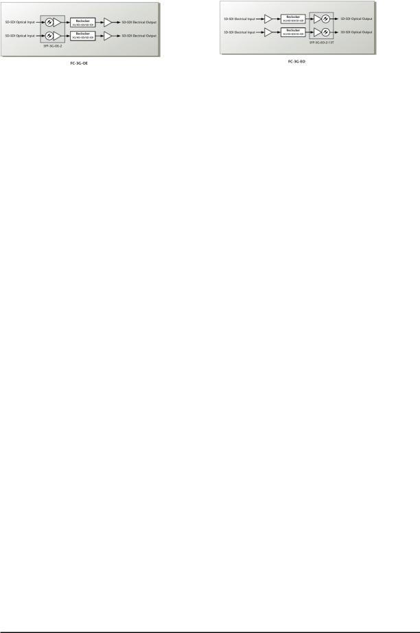
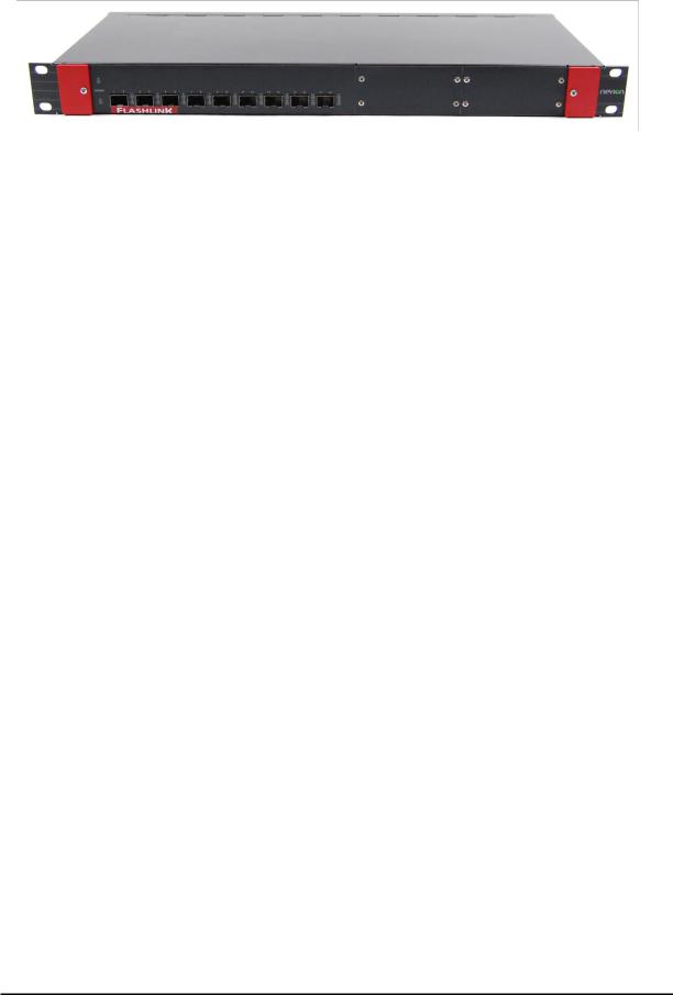
The Flashlink compact II is a range of low power, low price and small form factor optical to electrical converters. It can convert up to 36 channels in 1RU and optically multiplex all channels onto two fibers with the use of two optional 18 channel CWDM filters. Both EO and OE converters have an SD/HD/3G-SDI reclocker and supports bypass for none broadcast bitrates. The Flashlink Compact II can be controlled and monitored by Multicon Gyda or configured to be a standalone converter. The optical conversions are based on Nevion’s hot pluggable SFP modules. The Flashlink Compact II is equipped with an extra power inlet for dual power supply redundancy, either from an extra SL-PWR-40/SL-PWR- 90, the 1RU FC-PWR or battery pack.
1.1 Product versions
FC-3G-EO-18 |
18 channel electrical to optical converter |
FC-3G-OE-18 |
18 channel electrical to optical converter |
FC-3G-EO-36 |
36 channel electrical to optical converter |
FC-3G-OE-36 |
36 channel optical to electrical converter |
FC-3G-EO-OE-36 |
18 channel optical to electrical converter and |
|
18 channel electrical to optical converter |
FC-3G-EO-36+1C |
36 channel electrical to optical converter+ one |
|
CWDM filter |
FC-3G-OE-36+1C |
36 channel optical to electrical converter + one |
|
CWDM filter |
FC-3G-EO-OE-36+1C |
18 channel optical to electrical converter and+ one |
|
CWDM filter |
|
18 channel electrical to optical converter + one |
|
CWDM filter |
FC-3G-EO-36+2C |
36 channel electrical to optical converter + two |
|
CWDM filters |
FC-3G-OE-36+2C |
36 channel optical to electrical converter + two |
|
CWDM filters |
FC-3G-EO-OE-36+2C |
18 channel optical to electrical converter and |
|
18 channel electrical to optical converter + two |
|
CWDM filters |
All 18 channel versions are supplied with one SL-PWR-40
All 36 channel versions are supplied with one SL-PWR-90(can be used for all 18 channel versions without damage)
Extra powers supplies can be ordered for all versions.
nevion.com | 4

Flashlink Compact II Rev. A
2 Specifications
General |
|
Power |
+12V to 16V DC / |
|
48W, max(standard SFP) 36channel variants |
|
24W, max(standard SFP) 18 channel variants |
Size |
1.7” x 19” x 7.1” (H x W x D) |
|
43.4mm x 482.6mm x 180.0mm (H x W x D) |
Control |
Options for Multicon Gyda control and status |
|
BITE (Built-In Test Equipment) |
|
Status LED in front |
|
Configurations DIP in back |
Operating temperature |
0 to +45 °C |
Forced ventilation |
Four monitored fans, two on each side. |
|
Left to right airflow. |
Data rate reclocked: |
270, 1485, 1485/1.001, 2970, 2970/1.001 Mbps |
Data rate non-reclocked: |
1 to 2970 Mbps (Depending on SFP used) |
Supported standards |
|
SD, 270Mbps |
SMPTE259M |
HD, 1485Mbps |
SMPTE292-2008 |
3G, 2999Mbps |
SMPTE424M |
DVB-ASI |
EN50083-9. |
Fiber Transmission |
SMPTE297-2006 |
Electrical connector, BC |
IEC 61169-8 |
AES-3id (non-reclocked) |
|
AES-10/MADI (non-reclocked) |
|
Optical SDI input
See Nevion SFP datasheets for specification.
Optical SDI output
See Nevion SFP datasheets for specification.
nevion.com | 5

Flashlink Compact II |
Rev. A |
|
|
|
|
Electrical SDI input |
|
|
Connectors |
BNC, IEC 61169-8 |
|
Impedance |
75ohm |
|
Cable equalization |
Automatic; |
|
|
350m @270Mbps w/Belden 8281 |
|
|
250m @1485Mbps w/Belden 1694A |
|
|
150m @ 2970Mbps w/Belden 1694A |
|
Input Return loss |
>15dB, 5-1485MHz |
|
|
>10dB, 1485-2970MHz |
|
Electrical SDI outputs |
|
|
Connectors |
BNC, IEC 61169-8 |
|
Impedance |
75ohm |
|
Output signal level |
800mV +/- 10% |
|
Output signal rise / fall time |
20% - 80% |
|
|
- SD, 0.4ns – 1.5ns, <0.5ns rise/fall variation |
|
|
- HD/3G, < 270ps, <100ps rise/fall variation |
|
DC-offset |
0V +/-0,5 |
|
Amplitude overshoot |
<10% |
|
Output return loss |
>15dB, 5-1485MHz |
|
|
>10dB, 1485-2970MHz |
|
18 channel CWDM filter |
|
|
Number of channels |
18 |
|
Available wavelengths (nm) |
1271, 1291, 1311, 1331, 1351, 1371, 1391, 1411, 1431, |
|
|
1451, 1471, 1491, 1511, 1531, 1551, 1571, 1591, 1611 |
|
Connector |
LC/UPC |
|
Insertion loss (end to end, including |
5dB typical |
|
connectors) |
6dB max |
|
Channel Spacing |
20nm |
|
Passband |
13nm min |
|
Transmission circuit fibre |
9/125um single mode |
|
Adjacent Channel Isolation |
30dB min |
|
Non-Adjacent Channel Isolation |
40dB min |
|
Directivity |
45dB min |
|
Connector Return loss |
45dB min |
|
Polarization depending loss |
0.2dB max |
|
Ripple in passband |
0.5dB max |
|
Operating Temperature |
0 – 70 oC |
|
Storage Temperature |
-40 – 85 oC |
|
Optical Power |
17mW max |
|
nevion.com | 6

Flashlink Compact II |
Rev. A |
|
|
2.1 Front view
2.1.1 FC-3G-EO-18
Power A indicator: |
Gives status on power supply connected to the Power A connector on |
|
the back side. |
|
Green: Power supply connected |
|
Orange: No or none working power supply connected |
|
Red: The lower converter is malfunctioning. Please contact |
|
Nevion support for advice. |
Power B indicator: |
Gives status on power supply connected to the Power B connector on |
|
the back side. |
|
Green: Power supply connected |
|
Orange: No or none working power supply connected |
|
Red: The lower converter is malfunctioning. Please contact |
|
Nevion support for advice. |
1 to 18 indicators: |
Gives status per SFP converter channel. |
|
Green: Valid input signal and reclocker in lock or bypass. |
|
Orange: Signal on input, but reclocker not in lock. |
|
Red: No valid input signal. |
|
No light: No valid Nevion SFP present. |
SFP: |
Cage for fitting dual transmitter non-MSA SFPs. |
nevion.com | 7

Flashlink Compact II |
Rev. A |
|
|
2.1.2 FC-3G-EO-36
Power A indicator: |
Gives status on power supply connected to the Power A connector on |
|
the back side. |
|
Green: Power supply connected |
|
Orange: No or none working power supply connected |
|
Red: The lower converter is malfunctioning. Please contact |
|
Nevion support for advice. |
Power B indicator: |
Gives status on power supply connected to the Power B connector on |
|
the back side. |
|
Green: Power supply connected |
|
Orange: No or none working power supply connected |
|
Red: The lower converter is malfunctioning. Please contact |
|
Nevion support for advice. |
1 to 18 indicators: |
Gives status per SFP converter channel. |
|
Green: Valid input signal and reclocker in lock or bypass. |
|
Orange: Signal on input, but reclocker not in lock. |
|
Red: No valid input signal. |
|
No light: No valid Nevion SFP present. |
Upper SFP: |
Cage for fitting dual transmitter non-MSA SFPs. |
Lower SFP: |
Cage for fitting dual transmitter non-MSA SFPs. |
nevion.com | 8

Flashlink Compact II |
Rev. A |
|
|
2.1.3 FC-3G-OE-18
Power A indicator: |
Gives status on power supply connected to the Power A connector on |
|
the back side. |
|
Green: Power supply connected |
|
Orange: No or none working power supply connected |
|
Red: The lower converter is malfunctioning. Please contact |
|
Nevion support for advice. |
Power B indicator: |
Gives status on power supply connected to the Power B connector on |
|
the back side. |
|
Green: Power supply connected |
|
Orange: No or none working power supply connected |
|
Red: The lower converter is malfunctioning. Please contact |
|
Nevion support for advice. |
1 to 18 indicators: |
Gives status per SFP converter channel. |
|
Green: Valid input signal and reclocker in lock or bypass. |
|
Orange: Signal on input, but reclocker not in lock. |
|
Red: No valid input signal. |
|
No light: No valid Nevion SFP present. |
SFP: |
Cage for fitting dual receivers, non-MSA SFPs . |
nevion.com | 9
 Loading...