

Page 1
NX4600 Media Gateway
User’s Manual
Revision: 1.8.6 (5027)
2016-06-03
Valid for SW version 1.8.6.
nevion.com
Page 2

Page 3

Contents
1 History 11
2 Introduction 13
2.1 Scope 13
2.2 Warnings, cautions and notes 13
2.3 Heed warnings 14
2.4 Contact information 14
3 Short Product Description 15
3.1 Software options 16
3.2 Hardware options 16
4 Installing the Equipment 17
4.1 Inspect the package content 17
4.2 Installation Environment 17
4.3 Equipment installation 18
4.4 Ventilation 18
4.5 Power supply 19
4.5.1 AC power supply 19
4.5.1.1 Dual AC power supplies 19
4.5.1.2 AC power cable 19
4.5.1.3 Protective Earth/technical Earth 20
4.5.1.4 Connecting to the AC power supply 20
4.5.2 Powering up/down 21
5 Functional Description 23
5.1 Inputs 23
5.2 Monitoring 24
5.3 Seamless IP Protection Switching 24
5.4 Management subsystem 25
5.4.1 Graphical user interface 26
5.4.2 Configuration database 26
5.4.3 Alarm manager 27
5.5 Time synchronisation 27
6 Physical Description 29
6.1 Slot and port numbering scheme 29
6.2 ASI inputs 30
6.3 1PPS input 31
6.4 Alarm/Reset interface 31
Page 4

6.5 Ethernet ports 32
6.5.1 SFP+ ports 32
6.6 USB port 32
6.7 Technical Earth 32
6.8 Mains power connector 32
6.9 I/O daughter boards 32
6.9.1 H.264/AVC Codec Board 33
6.9.2 ASI Board 33
6.9.3 DVB S/S2 Board 34
6.10 Front Panel Display 34
6.10.1 Using the Front Panel Display 34
7 Operating the Equipment 37
7.1 Accessing the graphical user interface 37
7.2 Password protection 37
7.3 Changing the IP address of the unit 38
7.3.1 Changing IP address via the Web GUI 38
7.3.2 Changing the management port IP address via the terminal interface 39
7.3.3 Changing the IP address via the display 40
7.3.4 Changing the IP address via Detect 40
7.4 Software upgrade 41
7.4.1 NX-HW-S/S2-DEMOD-X2 41
8 WEB Interface 43
8.1 Login 43
8.2 Status header 44
8.3 Status 45
8.3.1 Device Status 46
8.3.2 Elements Status 46
8.3.3 Input Status 47
8.3.4 Thumbnails 47
8.3.5 Current alarms 47
8.3.6 Alarm log 48
8.3.6.1 Live Log 48
8.4 Device Info 51
8.4.1 Product info 51
8.4.2 Alarms 53
8.4.2.1 System alarm config 54
8.4.2.2 System alarm log 54
8.4.2.3 Alarm profiles 55
8.4.2.4 Alarm definitions 55
8.4.3 Chassis Config 55
8.4.4 Time Settings 57
8.4.5 TXP Settings 58
8.4.6 SNMP Settings 59
Page 5

8.4.7 Configuration Manager 60
8.4.7.1 Save/Load Configs 60
8.4.7.1.1 Save Configuration To File 60
8.4.7.1.2 Load Configuration From file 61
8.4.7.1.3 Load options 61
8.4.7.2 Stored Configurations 62
8.4.8 Maintenance 63
8.4.8.1 General 63
8.4.8.2 Software Upgrade 64
8.4.8.2.1 FTP upgrade 65
8.4.8.3 Features 65
8.4.9 Users 67
8.4.10 GUI Preferences 68
8.5 Network 69
8.5.1 Network overview 70
8.5.1.1 IP Routes 70
8.5.1.1.1 Adding a new IP route 70
8.5.1.1.2 Removing an existing IP route 71
8.5.1.1.3 Applying IP routing changes 71
8.5.1.1.4 Configuring a default gateway for the device 71
8.5.1.2 IP Ping 72
8.5.1.3 IP Snooper 73
8.5.2 Ethernet port 75
8.5.2.1 IP Interface 75
8.5.2.2 Ethernet 76
8.5.2.3 Ethernet alarms 78
8.5.2.4 VLAN 78
8.6 Inputs 79
8.6.1 Inputs Overview 79
8.6.1.1 IP input wizard 80
8.6.1.2 ASI Inputs 83
8.6.1.3 IP Inputs 84
8.6.1.4 SDI Inputs 86
8.6.1.4.1 SDI Configuration 87
8.6.1.4.2 SDI Status Section 87
8.6.1.4.3 Audio Channel Info 87
8.6.1.4.4 Thumbnail 87
8.6.1.5 DVB-S/S2 Inputs 87
8.6.2 Input 89
8.6.2.1 Main 90
8.6.2.1.1 Main (ASI input) 90
8.6.2.1.2 Main (IP input) 93
8.6.2.1.3 Main (DVB-S/S2 input) 95
8.6.2.2 Alarms 97
8.6.2.2.1 TS alarms 97
8.6.2.2.2 Alarm Log and SLA 100
8.6.2.3 IP 102
Page 6

8.6.2.3.1 Main 103
8.6.2.3.2 Seamless IP Protection Switching 105
8.6.2.3.3 FEC 107
8.6.2.3.4 Buffer regulator 109
8.6.2.3.5 Statistics 112
8.6.2.3.6 Inter Arrival Time 112
8.6.2.4 PIDs 114
8.6.2.4.1 PIDs Grid 114
8.6.2.4.2 PID rates 116
8.6.2.4.3 PID Types 116
8.6.2.4.4 Type Rates 117
8.6.2.5 Services 117
8.6.2.5.1 Service List 117
8.6.2.6 Tables 122
8.6.2.6.1 Tables 122
8.6.2.6.2 Sources 124
8.6.2.6.3 Settings 125
8.6.2.7 PCR 126
8.6.2.8 Packet Dump 129
8.6.2.9 S/S2 131
8.6.2.9.1 Main 132
8.6.2.9.2 LNB settings 135
8.6.2.9.3 Constellation 136
8.6.2.9.4 Statistics 136
8.7 Transform 138
8.7.1 Input Switch 138
8.7.1.1 General settings 139
8.7.1.2 Add/Remove Input 139
8.7.1.3 Automatic Mode 139
8.7.1.4 Manual Mode 140
8.8 Encoder/Decoder 140
8.8.1 Encoder/Decoder Overview 140
8.8.2 Encoder 141
8.8.2.1 Main 142
8.8.2.1.1 General Settings 143
8.8.2.1.2 Video Encoding 143
8.8.2.1.3 Audio Stream 144
8.8.2.1.4 Encoder Status 144
8.8.2.1.5 Thumbnail 144
8.8.2.1.6 Destinations 144
8.8.2.2 Alarms 144
8.8.2.2.1 Encoder alarms 145
8.8.2.3 Video 145
8.8.2.3.1 Main Settings 145
8.8.2.3.2 Advanced Settings 146
8.8.2.3.3 Advanced H264/MPEG2 Settings 147
8.8.2.3.4 Encoding Status 147
Page 7

8.8.2.3.5 Current Encoder Settings 147
8.8.2.4 Audio 147
8.8.2.5 VBI/ANC Config 148
8.8.2.5.1 VBI Settings 149
8.8.2.5.2 SMPTE 2038 Ancillary data 149
8.8.2.5.3 Ancillary data filter 149
8.8.2.5.4 Anc present 149
8.8.2.6 TS Config 149
8.8.2.6.1 PID Settings 149
8.8.2.6.2 PSI/SI Settings 150
8.8.2.7 Advanced 151
8.8.2.7.1 Signal Loss Settings 151
8.8.2.7.2 Framestore setting 152
8.8.2.7.3 Uploaded Test Image 152
8.8.3 Decoder 152
8.8.3.1 Main 153
8.8.3.1.1 Settings 153
8.8.3.1.2 Decoder source settings 154
8.8.3.1.3 Tune mode 154
8.8.3.1.4 Automatic 154
8.8.3.1.5 Service ID 154
8.8.3.1.6 Manual 154
8.8.3.1.7 Decoding status 154
8.8.3.1.8 Thumbnail 154
8.8.3.1.9 Source details 154
8.8.3.1.10 Destinations 154
8.8.3.2 Alarms 155
8.8.3.2.1 Deocder alarms 155
8.8.3.3 Audio 155
8.8.3.3.1 Currently Decoded Audio Streams 155
8.8.3.4 VBI/ANC Config 156
8.8.3.4.1 Vbi Settings 156
8.8.3.4.2 Smpte2038 Generic ANC 157
8.8.3.4.3 Ancillary data filter 157
8.8.3.4.4 ANC present 157
8.8.3.5 Advanced 157
8.8.3.5.1 Reference Sync Settings 158
8.8.3.5.2 Reference Sync Source 158
8.8.3.5.3 Signal Loss Settings 158
8.8.3.5.4 Uploaded Test Image 159
8.9 Outputs 159
8.9.1 Outputs Overview 159
8.9.2 ASI Output 160
8.9.2.1 Main 160
8.9.3 SDI Output 160
8.9.3.1 Main 160
8.10 Outputs 161
Page 8

8.10.1 Outputs Overview 161
8.10.1.1 ASI Outputs 162
8.10.1.2 IP Outputs 162
8.10.2 Output 163
8.10.2.1 Main tab 163
8.10.2.1.1 Main (ASI output) 163
8.10.2.1.2 Main (IP output) 164
8.10.2.2 Alarms 166
8.10.2.3 IP Destinations 167
8.10.2.3.1 Main 167
8.10.2.3.2 FEC 169
8.10.2.3.3 Ping 170
8.10.2.3.4 Advanced 171
8.10.3 RIPv2 172
9 SNMP 177
9.1 SNMP agent characteristics 177
9.2 MIB overview 177
9.2.1 Supported standard MIBs 177
9.2.2 Custom MIBs 177
9.2.3 How to use the MIB 178
9.3 Alarm/status related SNMP TRAPs 179
9.3.1 The main trap messages 179
9.3.2 Severity indications 180
9.3.3 Alarm event fields 180
9.3.4 Matching of on/off traps 181
10 Preventive Maintenance and Fault-finding 183
10.1 Preventive maintenance 183
10.1.1 Routine inspection 183
10.1.2 Cleaning 183
10.1.3 Servicing 183
10.1.4 Warranty 184
10.2 Fault-finding 184
10.2.1 Preliminary checks 184
10.2.2 PSU LED not lit / power supply problem 185
10.2.3 Fan(s) not working / unit overheating 186
10.3 Disposing of this equipment 186
10.4 Returning the unit 186
A Glossary 187
B Technical Specification 193
B.1 Physical details 193
B.1.1 Full-width (dual power) version 193
B.2 Environmental conditions 193
Page 9

B.3 Power 193
B.3.1 AC Mains supply 193
B.4 Input/output ports 194
B.4.1 HD-SDI port 194
B.4.2 DVB ASI port 194
B.4.3 DVB-S/S2 board 194
B.4.4 Ethernet ports 195
B.4.5 Serial USB interface 195
B.5 Alarm ports 195
B.5.1 Alarm relay/reset port specification 195
B.6 Compliance 196
B.6.1 Safety 196
B.6.2 Electromagnetic compatibility - EMC 196
B.6.3 CE marking 197
B.6.4 Interface to “public telecommunication system” 197
C Forward Error Correction in IP Networks 199
C.1 IP stream distortion 199
C.2 Standardisation 200
C.3 FEC matrix 200
C.4 Transmission aspects 203
C.5 Quality of service and packet loss in IP networks 204
C.6 Error improvement 205
C.7 Latency and overhead 206
D Alarms 209
E References 223
Page 10

Page 11

1 History
History 11
Revision Date Comments
1.8.6 2016-06-03 – Updated for new SW version
1.6.14 2016-01-19 – Updated for new SW version
1.4.10 2015-10-05 – Updated for new SW version
1.2.12 2015-05-05 – Updated for new SW version
0.4.0 Draft 2015-01-05 – Initial DRAFT version
ID: mediagateway NX4600 User’s Manual Rev. 1.8.6 (5027)
Page 12

12
NX4600 User’s Manual Rev. 1.8.6 (5027) ID: mediagateway
Page 13
Introduction 13
2 Introduction
2.1 Scope
This manual is written for operators and users of the NX4600 Media Gateway and provides necessary information for installation, operation and day-to-day maintenance of the unit. The manual
covers the functionality of the software version 1.8.6 or later, and continues to be relevant to subsequent software versions where the functionality of the equipment has not been changed. When a
new software version changes the functionality of the product, an updated version of this manual
will be provided.
The manual covers the following topics:
• Getting started
• Equipment installation
• Operating instructions
• WEB interface description
• Preventive maintenance and fault finding
• Alarm listing
• Technical specifications
2.2 Warnings, cautions and notes
Throughout this manual warnings, cautions and notes are highlighted as shown below:
Warning: This is a warning. Warnings give information, which if strictly
observed, will prevent personal injury and death, or damage to personal
property or the environment.
Caution: This is a caution. Cautions give information, which if strictly
followed, will prevent damage to equipment or other goods.
Note: Notes provide supplementary information. They are highlighted for
emphasis, as in this example, and are placed immediately after the relevant
text.
ID: mediagateway NX4600 User’s Manual Rev. 1.8.6 (5027)
Page 14

14 Introduction
2.3 Heed warnings
• All warnings marked on the product and in this manual should be adhered to. The
manufacturer cannot be held responsible for injury or damage resulting from negligence of warnings and cautions given.
• All the safety and operating instructions should be read before this product is installed
and operated.
• All operating and usage instructions should be followed.
• The safety and operating instructions should be retained for future reference.
2.4 Contact information
Our primary goal is to provide first class customer care tailored to your specific business and
operational requirements.
Please contact us at:
Telephone +47 22 88 97 50
Fax +47 22 88 97 51
E-mail support@nevion.com
WEB http://www.nevion.com
Mail and visiting address Nevion
Nils Hansens vei 2
NO-0667 Oslo
Norway
NX4600 User’s Manual Rev. 1.8.6 (5027) ID: mediagateway
Page 15

Short Product Description 15
3 Short Product Description
The NX4600 is Nevion’s latest generation H.264/AVC compression platform, offering simultaneous encoding and decoding in a compact 1RU form factor.
The NX4600 is an encoder, decoder and media edge adapter all built into one. Up to four baseband
SDI video signals can be encoded using H.264/AVC or MPEG-2 compression and transported over
ASI and IP.
It is also possible to combine encoding and decoding in the same unit which increases flexibility
in deployment of new services and gives a very tight and compact offering for outside broadcast
production applications (sports, news and other live events) and managed media services.
The H.264/AVC Media Gateway includes Nevion’s trademark advanced protection mechanisms
that enable real-time transport of professional media over IP networks with extremely high availability. The NX4600 offers built-in aggregation of TS over IP streams on one or multiple GbE ports.
It’s our goal to offer products that are reliable and easy to use. Therefore, the NX4600 offers an
intuitive and dynamic web interface that offers built-in Transport Stream monitoring of both encoder outputs and decoder inputs, as well as SDI and RTP/IP monitoring - all of which helps
anticipate and correct any issues with input signals or networks should they arise.
Salient features of the NX4600 are:
• PSI/SI table decoding
− Repetition rate monitoring
− Full decoding of all standard PSI/SI tables and descriptors
− Monitoring of ASI and IP encapsulated transport streams
− TR 101 290 Priority 1 monitoring: Sync loss, CC error
− TR 101 290 Priority 2 monitoring: PCR jitter, PTS error
− TR 101 290 Priority 3 monitoring: SI repetition rates
− Monitoring of min/max bitrate for individual PIDs
• Flexible alarm configuration options
− Alarm levels freely configurable individually for each channel
− Individual setting of alarm levels based on PID values
• User-friendly configuration and control
− WEB/XML based remote control
− Easy access to unit from any WEB browser
ID: mediagateway NX4600 User’s Manual Rev. 1.8.6 (5027)
Page 16

16 Short Product Description
− Easy integration to NMS systems with SNMP Trap support
− SNMPv2c agent
• Reception of transport stream over Gigabit Ethernet
3.1 Software options
The NX4600 functionality depends on the software licences installed. The following table describes the features available as software options. Please refer to Section 8.4.8.3 for more information how to obtain and enable feature upgrades.
Table 3.1 Functionality enabled through software licences
Code Max nb
of ports
AMMX 50 Enables advanced monitoring on multi-program
TSOX 80 Enables output of Transport Streams over IP IP outputs
ISWX 50 Enables TS Input switching functionality TS Input Switching
FEC - Enables support for Forward Error Correction on
SIPS - Enables Seamsless IP Protection SIPS
LDO - Enables Launch Delay Offset LDO
Description Key features
ETR 290 Pri 2 and 3, PCR, Table decoding,
transport stream (MPTS)
video data traffic.
Packet dump
FEC
3.2 Hardware options
The NX4600 comes with a variety of hardware options. The product can be ordered with up to
four daughter boards in order to tailor to specific needs in terms of inputs to monitor.
Currently, the four slots on the NX4600 can be populated with any combination of the daughter
boards listed below.
• ASI board (4xASI BNC inputs/outputs)
• H.264/AVC Encoder/Decoder Boards
• DVB-S/S2 board (2xDVB-S/S2 F-connector inputs and 2xASI BNC test outputs)
NX4600 User’s Manual Rev. 1.8.6 (5027) ID: mediagateway
Page 17

Installing the Equipment 17
4 Installing the Equipment
Caution: The NX4600 must be handled carefully to prevent safety hazards
and equipment damage. Ensure that the personnel designated to install
the unit have the required skill and knowledge. Follow the instructions
for installation and use only installation accessories recommended by the
manufacturers.
4.1 Inspect the package content
• Inspect the shipping container for damage. Keep the shipping container and cushioning
material until you have inspected the contents of the shipment for completeness and have
checked that the NX4600 is mechanically and electrically in order.
• Verify that you received the following items:
− NX4600 with correct power supply option
− Power cord(s)
− CD-ROM containing documentation and Flash Player installation files
− Any optional accessories you have ordered
4.2 Installation Environment
As with any electronic device, the NX4600 should be placed where it will not be subjected to
extreme temperatures, humidity, or electromagnetic interference. Specifically, the selected site
should meet the following requirements:
• The ambient temperature should be between 0 and 50◦C (32 and 122◦F).
• The relative humidity should be less than 95 %, non-condensing. Do not install the unit
in areas of high humidity or where there is danger of water ingress.
• Surrounding electric devices should comply with the electromagnetic field (EMC) standard IEC 801-3, Level 2 (less than 3 V/m field strength).
• The AC power outlet (when applicable) should be within 1.8 meters (6 feet) of the NX4600.
• Where appropriate, ensure that this product has an adequate level of lightning protec-
tion. Alternatively, during a lightning storm or if it is left unused and unattended for
long periods of time, unplug it from the power supply and disconnect signal cables. This
prevents damage to the product due to lightning and power-line surges.
ID: mediagateway NX4600 User’s Manual Rev. 1.8.6 (5027)
Page 18
18 Installing the Equipment
CP541
Cool
Air In
Warm
Air Out
Warning: If the NX4600 has been subject to a lightning strike or a power
surge which has stopped it working, disconnect the power immediately.
Do not re-apply power until it has been checked for safety. If in doubt
contact Nevion.
4.3 Equipment installation
The NX4600 is designed for stationary use in a standard 19" rack. When installing please observe
the following points:
• Route cables safely to avoid them being pinched, crushed or otherwise interfered with.
Do not run AC power cables and signal cables in the same duct or conduit.
• The NX4600 has all connectors at the rear. When mounting the unit, ensure that the
installation allows easy access to the rear of the unit.
• The fans contained in this unit are not fitted with dust/insect filters. Pay particular attention to this when considering the environment in which it shall be used.
• Make sure that the equipment is adequately ventilated. Do not block the ventilation holes
on each side of the NX4600.
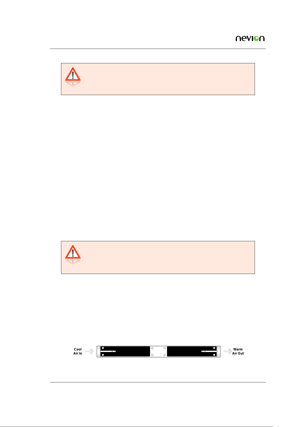
4.4 Ventilation
Openings in the cabinet are provided for ventilation to protect it from overheating and ensure
reliable operation. The openings must not be blocked or covered. Allow at least 50 mm free airspace each side of the unit.
Warning: Never insert objects of any kind into this equipment through
openings as they may touch dangerous voltage points or create shorts that
could result in a fire or electric shock. Never spill liquid of any kind on or
into the product.
• This product should never be placed near or over a radiator or heat register. Do not place
in a built-in installation (e.g. a rack) unless proper ventilation is provided in accordance
with the device airflow design as depicted in Figure 4.1 .
• The NX4600 may be vertically stacked in 19" racks without intermediate ventilation panels. In systems with stacked units forced-air cooling may be required to reduce the operating ambient temperature.
Figure 4.1 shows the air path through the unit, where cool air is taken from the left hand
side, seen from the front.
Figure 4.1 Air path through the unit
NX4600 User’s Manual Rev. 1.8.6 (5027) ID: mediagateway
Page 19
Installing the Equipment 19
4.5 Power supply
The NX4600 is delivered rated for AC operation.
Warning: This product should be operated only from the type of power
source indicated on the marking label. Please consult a qualified electrical
engineer or your local power company if you are not sure of the power
supplied at your premises.
4.5.1 AC power supply
The NX4600 has a wide-range power supply accepting the voltage range 100-240 VAC, 50/60 Hz.
Please refer to
4.5.1.1 Dual AC power supplies
Alternatively, the NX4600 may be fitted with dual internal wide-range AC power supplies. The
power supplies cover the voltage range 100-240 VAC, 50/60 Hz.
Appendix B for a detailed specification of the AC power supply.
During normal operation, load-sharing is used between the internal supplies. In case of a single
power supply failure alarms will be raised and the unit will continue operating off the second
power supply. To guard against failure in the external power circuitry it is imperative to connect
each power supply to separate AC mains circuits.
Please refer to Appendix B for a detailed specification of the AC power supply.
4.5.1.2 AC power cable
Ensure that the AC power cable is suitable for the country in which the unit is to be operated.
Caution: Power supply cords should be routed so that they are not likely
to be trod on or pinched by items placed upon or against them. Pay
particular attention to cords at plugs and convenience receptacles.
The unit is supplied with a two meter detachable mains supply cable equipped with a moulded
plug suitable for Europe, UK or USA, as appropriate. The wires in the mains cable are coloured
in accordance with the wire colour code shown in Table 4.1.
Table 4.1 Supply cable wiring colours
Wire UK (BS 1363) EUROPE (CEE 7/7) USA (NEMA 5-15P)
Earth Green-and yellow Green-and yellow Green
Neutral Blue Blue White
Live Brown Brown Black
ID: mediagateway NX4600 User’s Manual Rev. 1.8.6 (5027)
Page 20
20 Installing the Equipment
4.5.1.3 Protective Earth/technical Earth
To achieve protection against earth faults in the installation introduced by connecting signal cables
etc., the equipment should always be connected to protective earth. If the mains supply cable is
disconnected while signal cables are connected to the equipment, an earth connection should be
ensured using the Technical Earth connection terminal on the rear panel of the unit.
Warning: This unit must be correctly earthed through the moulded plug
supplied. If the local mains supply does not provide an earth connection
do not connect the unit.
Caution: Consult the supply requirements in Appendix B prior to connecting the unit to the supply.
The unit has a Technical Earth terminal located in the rear panel. Its use is recommended. This is
not a protective earth for electrical shock protection; the terminal is provided in order to:
1. Ensure that all equipment chassis fixed in the rack are at the same technical earth potential. To achieve this, connect a wire between the Technical Earth terminal and a suitable
point in the rack. To be effective all interconnected units should be earthed this way.
2. Eliminate the migration of stray charges when interconnecting equipment.
Warning: If the terminal screw has to be replaced, use an M4x12mm long
pozidrive pan head. Using a longer screw may imply a safety hazard.
4.5.1.4 Connecting to the AC power supply
Warning: Do not overload wall outlets and extension cords as this can
result in fire hazard or electrical shock. The unit is not equipped with an
on/off switch. Ensure that the outlet socket is installed near the equipment
so that it is easily accessible. Failure to isolate the equipment properly may
cause a safety hazard.
To connect the unit to the local AC power supply, connect the AC power lead to the NX4600 mains
input connector(s) and then to the local mains supply.
NX4600 User’s Manual Rev. 1.8.6 (5027) ID: mediagateway
Page 21

Installing the Equipment 21
4.5.2 Powering up/down
Before powering-up the unit, please ensure that:
• The unit is installed in a suitable location
• The unit has been connected to external equipment as required
Power up the unit by inserting the power cable connected to the power source. When the unit has
finished the start-up procedure, the fans will run at normal speed. Please check that all cooling
fans are rotating. If they are not, power down the unit immediately.
Power down the unit by removing the power supply connector at the rear of the unit.
ID: mediagateway NX4600 User’s Manual Rev. 1.8.6 (5027)
Page 22

22
NX4600 User’s Manual Rev. 1.8.6 (5027) ID: mediagateway
Page 23
Functional Description 23
5 Functional Description
The NX4600 Media Gateway is an encoder, decoder and media edge adapter that takes up to three
(fixed chassis), or four (modular chassis) baseband SDI video signals, compresses them using
H.264/AVC or MPEG-2, and aggregates and transmits the streams over IP/Ethernet. It is also
possible to combine encoding and decoding in the same 1RU unit, which increases flexibility and
gives a very tight and compact offering for outsidebroadcast production applications (sports, news
and other live events) and managed media services.
NX4600 includes Nevion’strademark advanced protectionmechanisms that enable real-time transport of professional media over IP networks, as well as built-in monitoring that helps anticipate
and correct any issues with the network or transport should they arise.
Nevion Gateways can be configured via an easy-to-use web interface, which also offers extensive
built-in monitoring. Supervision and Connection management can be performed via Nevion’s
VideoIPath or any 3rd party Network Management System.
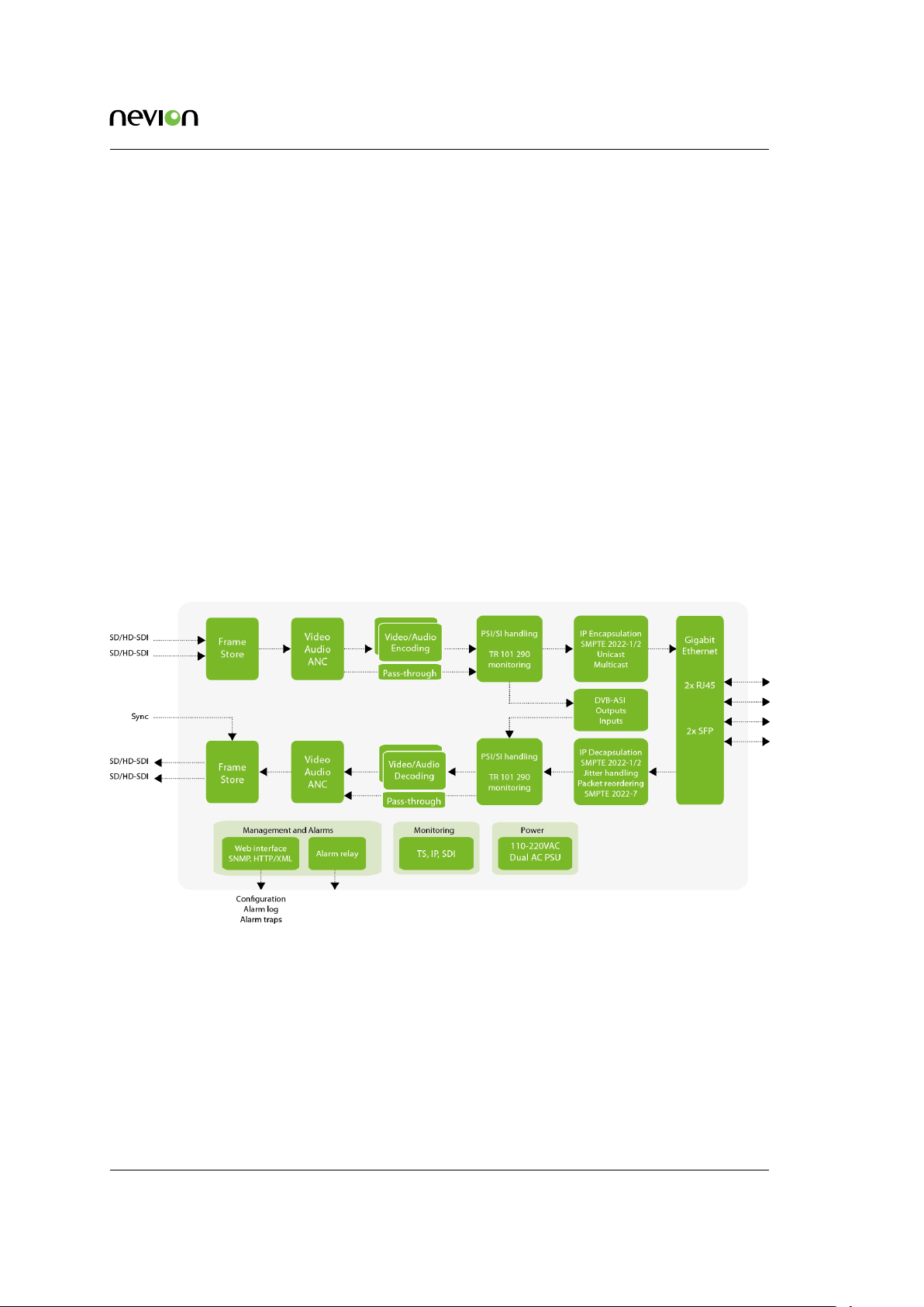
This chapter gives a brief description of the inner workings of the NX4600,
Figure
blocks are described in more detail in the following sections.
5.1 shows a functional block diagram of the main components inside NX4600. The different
Figure 5.1 NX4600 block diagram
5.1 Inputs
The input interfaces include up to twenty ASI inputs (BNC connectors) , up to eight DVB-S/S2
inputs , up to 3 SDI inputs per Daughter Board and four Ethernet inputs .
ID: mediagateway NX4600 User’s Manual Rev. 1.8.6 (5027)
Page 24
24 Functional Description
5.2 Monitoring
The Monitoring section provides monitoring of up to hundreds of transport streams on-the-fly. Parameters of the selected transport streams will be monitored and compared against specifications
and specific requirements. The values of critical components can be displayed graphically. An
extensive set of alarms may be programmed, with different severity levels. The content of selected
packets, or groups of packets, may be recorded for examination and/or documentation.
Measurements are made according to the DVB ETR 290 specifications.
5.3 Seamless IP Protection Switching
Seamless IP Protection Switching (SIPS) provides redundancy by protecting the media stream
against errors in the IP network, but in a different manner compared to Forward Error Correction
(FEC). FEC is designed to protect the stream against single or short burst packet losses, whereas
SIPS provides protectionagainst loss of complete data input, for example, due to link or equipment
failure.
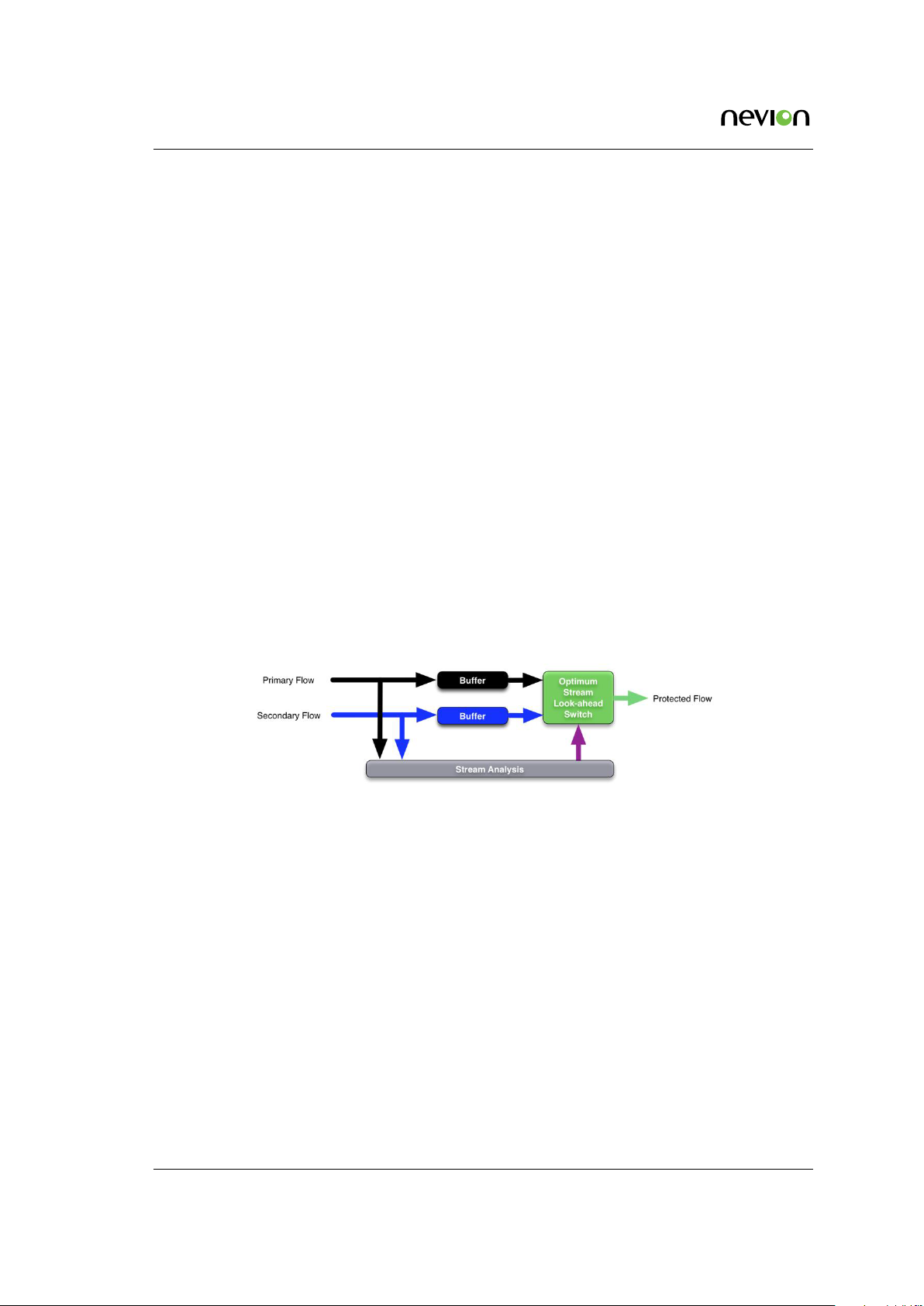
The main idea of SIPS is to transmit two identical copies of the media stream over separate network
paths. At the receiver side, the data from the two incoming streams are combined at packet level
to form an error free output data stream.
The combination of diverse path routing and perfect switching provides for the highest possible
Quality of Service, effectively minimizing the effects of random packet losses, burst packet losses,
losses due to fast reroutes, and link failures.
Figure 5.2 SIPS functional overview
Functional description
SIPS operates on the RTP packet level. The receive module buffers both incoming streams, mediating and selecting the most appropriate packets in what is termed active-active merging for use in
de-encapsulation. In this way, if one stream is impaired, good packets are delivered via the other
stream and a good output stream can always be reconstructed.
There will be packet loss at the combined stream only when the packet is received on neither of
the two IP sources. The data stream resulting from combining the two incoming data streams will
then be processed as one RTP packet stream.
Setup
At the transmitter side, the NX4600 allows sending identical copies of the data flow to a user defined list of destinations. When several destinations have been configured for transmission, media
streams are sent to different IP addresses but the streams are identical down to the RTP layer and
are tagged with the same, randomly generated Synchronization Source ID (SSRC). For each destination, the physical or logical VLAN network interface, and IP unicast or multicast destination
NX4600 User’s Manual Rev. 1.8.6 (5027) ID: mediagateway
Page 25

Functional Description 25
addresses are configured. This enables the two data streams to be routed to their respective network paths directly at the NX4600 or at the first subsequent network node. See Section 8.10.2.3
for more information on configuring redundant transmission/IP destinations.
At the receiver side SIPS must be enabled and the IP source parameters for IP flow A and B must
be configured to receive the media streams from the two diverse network paths. For any fully
seamless protection system to function, the dual media feeds presented at the receiver needs to
be essentially coherent i.e. the exact same media feed down to the RTP transport layer. When the
data streams have an identical SSRC value and data format, they are assumed to be identical and
are used for Seamless IP Protection Switching. See Section 8.6.2.3.2 for more info on configuration
of SIPS on the receiver.
Delay compensation
As the A and B flows will typically be routed across network links with different delays, it is
necessary for the SIPS module to wait for a period after the first signal is received before it starts
outputting data, to ensure that the second signal that is received does not need to be written to
the buffer after it is read out.
The SIPS Pre-buffer configuration parameter allows this period to be configured to allow the
system to be able to compensate for the maximum expected differential latency between the A
and B flows, while minimizing the additional delay added to the system.
Launch Delay Offset
If dual redundant network paths for some reason is not available, the Nevion patented technology
Launch Delay Offset (LDO) may be employed on the transmitter side.
This feature makes it possible to introduce a delay to one of the transmitted media streams, and
thereby introducing a temporal redundancy in the transmission. In this situation burst losses
approaching the time delay configured for LDO can be handled by the receiving SIPS engine,
even when only one network path is available.
Note that this setup will give protection against long burst losses, but not against complete network failure. If there is a need to protect against link failures, LDO should be used together with
redundant network paths (routing flow A and B through different network paths).
For information on how to configure LDO, see
Licensing
The SIPS feature requires a licence at the receiving node. No licence is required to configure multiple IP destinations for an output channel on the transmit side.
The LDO feature requires a licence at the transmitting node.
Compatibility
The SIPS feature is fully compatible with and extends the functionality of the SMPTE 2022-7
“Seamless Protection Switching of SMPTE ST 2022 IP Datagrams” standard.
Section 8.10.2.3.1.
5.4 Management subsystem
The management subsystem is a set of modules that handles all the interfaces to monitor and
control the operation of the NX4600.
ID: mediagateway NX4600 User’s Manual Rev. 1.8.6 (5027)
Page 26

26 Functional Description
The management subsystem communicates with the users, both humans and machines, via the
following interfaces:
• Front panel and back panel LEDs for status
• Graphical user interface via Flash application in WEB browser
• SNMP traps on alarms
• SNMPv2c Agent
• TXP (XML Protocol) to retrieve and set configuration and status
• Alarm relays on alarms
• Terminal interface either over Telnet or USB interface for debugging
• FTP server for direct file system access
The management subsystem communicates with other internal modules to make the unit perform
the wanted operations.
5.4.1 Graphical user interface
Operators monitor and control the NX4600 mainly via the Adobe Flash GUI application served
from the device’s WEB server. The GUI application is accessed via a WEB browser that communicates with the configuration framework through an HTTP/XML based protocol.
The device exposes extensive status information to the web GUI providing detailed reports and
real-time monitoring displays to the device administrator.
All the device configuration parameters available on the NX4600 can be controlled from the web
GUI.
5.4.2 Configuration database
The management subsystem processes configuration changes as transactions. All configuration
changes made to the device are validated against the current running configuration before committing them to the device. This limits the risks of the administrator implementing changes that
may cause down-time on the unit due to incompatible configuration settings.
Configurations can be imported and exported via the GUI. It is possible to clone the entire configuration of one device to another by exporting the configuration of one device and importing it to
another.
Configurations exported via the web GUI are formatted as human readable/modifiable XML files.
These files can be viewed or altered using any standard text or XML editor such as Windows
Notepad.
To simplify cloning of devices, certain exported parameters within the XML file are tagged as
device specific and therefore will be ignored when imported to either the same device or another.
These parameters are as follows:
• Device Name and Inventory ID
NX4600 User’s Manual Rev. 1.8.6 (5027) ID: mediagateway
Page 27

Functional Description 27
• IP network parameters
• ASI Port mappings
5.4.3 Alarm manager
The NX4600 contains an integrated alarm manager responsible for consistently displaying the
alarm status of each individual interface.
“Port Alarms” are alarms bound to a specific input or output port via a port indexing system.
The alarm severity for port related alarms can be configured per port level. “Device Alarms”
are global to the device and are not bound to any specific port. They do not follow the indexing
scheme. These are classified as “System Alarms”.
Alarms are graphically represented in a tree structure optimized for simplified individual viewing
and configuration. The “Device Alarm” tree is available from the “Device Info” page. The alarm
tree for each port is available on the “Alarms” page for each port.
The alarm manager presents the alarm of highest severity upon the external interfaces of the device. The severity level of each individual alarm can be defined by the administrator. Alarm
configuration is covered in greater detail in the “Alarm configuration” section.
SNMP traps are dispatched to registered receivers whenever there is an alarm status change.
The alarm manager keeps a log in non-volatile memory of the latest 100000 alarms that have occurred.
5.5 Time synchronisation
The NX4600 contains an internal real-time clock that is used for all internal timestamps. The internal clock is battery backed up in order to continue operating while the unit has no power.
The internal time can be synchronised as follows:
• Manual setting.
• From NTP server using SNTP protocol.
ID: mediagateway NX4600 User’s Manual Rev. 1.8.6 (5027)
Page 28

28
NX4600 User’s Manual Rev. 1.8.6 (5027) ID: mediagateway
Page 29
Physical Description 29
6 Physical Description
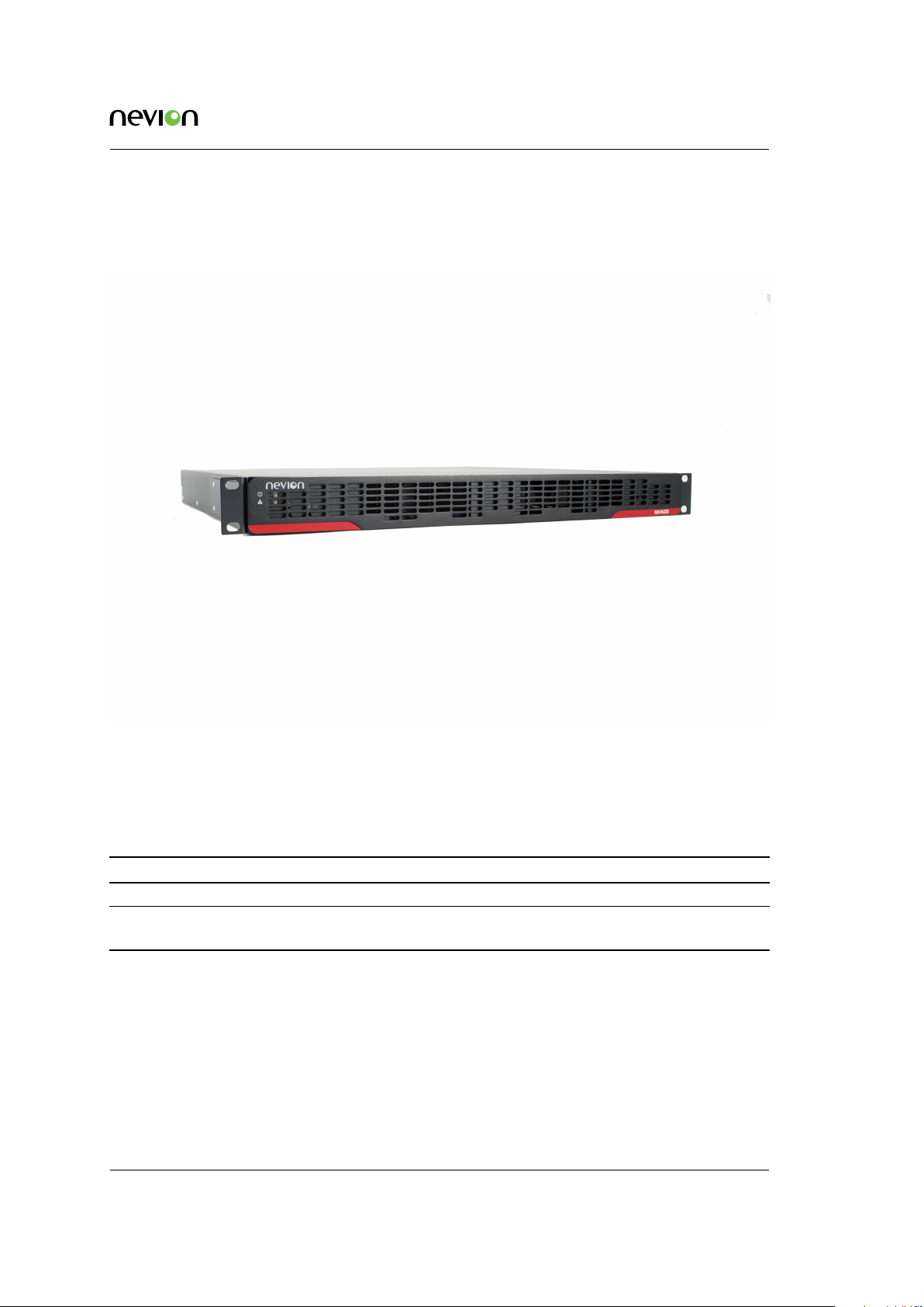
Figure 6.1 Front panel of NX4600
The front panel, figure 6.1, provides two LEDs per NX4600. The meaning of the LED indicators is
shown in table 6.1.
Table 6.1 Front panel LED descriptions
Indicator Colour Description
Power Green Indicates power ON and initialisation completed
Alarm Red Lit during reboot and when a critical alarm is active. The alarm severity level to activate the red
LED is configurable
6.1 Slot and port numbering scheme
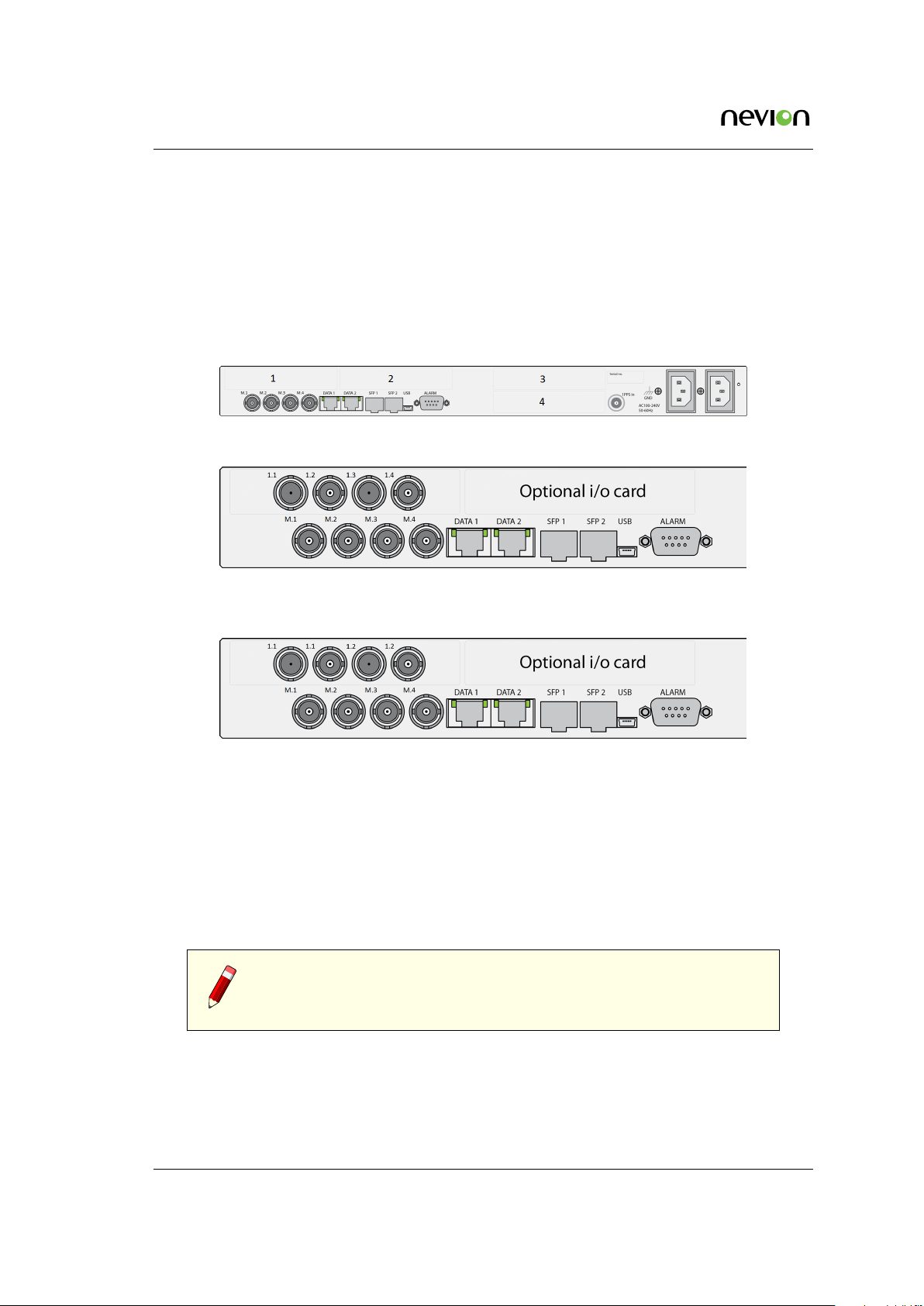
Figure 6.2 shows the rear panel of the NX4600, with no I/O daughter boards connected in the slots
which are numbered 1-4. These slots can contain up to four daughter boards in any combination
available from Nevion.
Figure 6.3 and 6.4 show the left half of the backplane as examples of one daughter board inserted
in slot number 1. These figures illustrate the port numbering scheme used consistently for the
ID: mediagateway NX4600 User’s Manual Rev. 1.8.6 (5027)
Page 30
30 Physical Description
NX4600. The numbering scheme contains two numbers, where the first is the slot number. The
main board has slot number M (for Main board) and the rest are as shown in figure 6.2. The second
number is an incrementing number, starting at 1, that increments for each extra addition of the
same connector. As an example, the ASI daughter board in slot number 1 would have numbered
the four BNC connectors as 1.1-1.4 as shown in figure 6.3. A DVB-S/S2 daughter board with two
F-connector antenna inputs and two BNC connectors for ASI test output will have a numbering
of 1.1 (first F-connector), 1.1 (first BNC output), 1.2 (second F-connector) and 1.2 (second BNC
output). This is shown in figure 6.4.
Figure 6.2 Rear panel showing slot numbering for NX4600.
Figure 6.3 Example of numbering scheme
using an ASI daughter board for NX4600.
Figure 6.4 Example of numbering scheme using an DVB-S/S2 daughter board for
NX4600.
6.2 ASI inputs
BNC connectors 1 through 4, as shown in figure 6.2 are input ports. Connect the transport stream
input signals to be monitored to any of these connectors. The signals connected to the these input
ports should be valid DVBor ATSC compliant transport streams accordingto the operational mode
of the unit.
Note: that the four slots, numbered 1-4 in figure 6.2 and the cards
contained in them (or the lack of card in them) may vary depending on
the product configuration ordered from Nevion.
NX4600 User’s Manual Rev. 1.8.6 (5027) ID: mediagateway
Page 31

Physical Description 31
6.3 1PPS input
This coaxial connector (labelled 1PPS/10MHz) is provided in order to enable locking the internal
system clock to a universal reference. A standard 1 pulse per second reference signal should be
applied, e.g. from a GPS receiver. 1PPS is used for more accurate PCR measurements, and is
required for SFN delay monitoring.
6.4 Alarm/Reset interface
The unit is equipped with a 9-pin male D-sub connector to provide alarm information. Two programmable relays are provided. The first relay is always activated on a critical alarm or when the
unit is not powered.
The pin-out of the connector is shown in table 6.2.
Table 6.2 Alarm/Reset
connector pin out
Pin Function
1. Relay 2 - Closed on alarm (NC)
2. Relay 2 Common
3. Relay 2 - Open on alarm (NO)
4. Prepared for +5V Output
5. Ground
6. Alarm Relay - Closed on alarm (NC)
7. Alarm Relay Common
8. Alarm Relay - Open on alarm (NO)
9. Optional Reset Input / GPI
Note: The Optional Reset Input / GPI is not currently not yet supported
in software, but will be supported in a later release.
If a critical (level 6) alarm has been raised, if the unit is not powered or any other programmed
condition for relay 1 is satisfied, there will be a connection between pin 6 and pin 7; otherwise,
there will be a connection between pin 7 and pin 8.
The optional (additional) relay will follow the same behaviour, except that it can also be programmed to be not activated for a critical (level 6) alarm.
A connection between pin 9 and 5 (or a TTL low on pin 9) will hold the unit in reset if this function
has been enabled. The connection must be held for 0.5 seconds in order to activate the reset. This
can be used to force a hard reset of the unit from an external control system. This pin can also be
used as a general purpose input (GPI).
For electrical specifications of the alarm connector, please refer to Appendix
cations).
ID: mediagateway NX4600 User’s Manual Rev. 1.8.6 (5027)
B (Technical Specifi-
Page 32

32 Physical Description
6.5 Ethernet ports
The NX4600 is equipped with four ethernet ports. Together, these allow monitoring of hundreds
of IP encapsulated MPEG transport streams. There is, however, an upper limit to the overall bit
rate of the transport streams that can be monitored simultaneously. Two of the ethernet ports are
Ethernet 1G data ports, Eth M.1 and Eth M.2.
The data port LEDs give the following information:
Speed indicator (left)
Unlit = 10 Mbit/s, green = 100 Mbit/s, yellow = 1000 Mbit/s
Traffic and link indicator (right)
Green - lit when link is established, blinks when data is transmitted or received.
6.5.1 SFP+ ports
The NX4600 provides twoslots to accommodate two SFP+ modules, labeled Eth M.3 and Eth M.4.
This will provide two additional Ethernet ports supporting fiber optical transmission.
Enabling of the SFP+ slot is done from the Networks->Ethernet M.3 or Networks->Ethernet M.4
pages.
6.6 USB port
The mini USB connector provides an IP network-independent means to configure and monitor
the NX4600. This is useful especially when the unit shall be introduced into a network already in
operation.
USB 1.1 standard is supported.
6.7 Technical Earth
Connect the Technical earth to a suitable system earth point.
6.8 Mains power connector
Figure
Section 4.5 provides details of the power supply, protective earth and security. Read these instructions carefully prior to connecting the unit to mains power.
6.2 shows the unit with an AC mains power connector.
6.9 I/O daughter boards
NX4600 User’s Manual Rev. 1.8.6 (5027) ID: mediagateway
Page 33

6.9.1 H.264/AVC Codec Board
Figure 6.5 Modular version of the H.264/AVC
Codec Board
Physical Description 33
The H.264/AVC Codec board can either be configured as an Encoder or a Decoder, and is available
for both the fixed and the modular chassis. In the current SW version (1.8.6) each port has the
following configurations:
• BNC 1: ASI Input in Decoder mode / SDI Input in Encoder mode
• BNC 2: SDI Input or SDI Output
• BNC 3: SDI Input or SDI Output
• BNC 4: Reference Sync Input or ASI Output
HW ID: NEO1401.4610
6.9.2 ASI Board
The ASI board is available for both the fixed and the modular chassis. In the current SW version
(1.8.6) each port has the following configurations (starting with the leftmost when looking at the
rear of the chassis):
• BNC 1: ASI Input / Output
• BNC 2: ASI Input / Output
• BNC 3: ASI Input / Output
• BNC 4: ASI Input / Output
HW ID: NEO1402.4213
ID: mediagateway NX4600 User’s Manual Rev. 1.8.6 (5027)
Page 34

34 Physical Description
6.9.3 DVB S/S2 Board
The DVB-S/S2 demodulator board is only available for the fixed chassis, and has a static port
configuration. In the current SW version (1.8.6) each port has the following configurations (starting
with the leftmost when looking at the rear of the chassis):
• F-connector 1: DVB-S/S2 L-band RF input
• BNC 1: ASI test output
• F-connector 2: DVB-S/S2 L-band RF input
• BNC 2: ASI test output
HW ID: NEO1301.4022
6.10 Front Panel Display
Note: The presence of a front display is optional.
The NX4600 contains a large, easy to read LCD display which is backlit, so it provides readable
characters even in environments with dark areas or bright sunlight.
To the right of the display is an associated keypad which is backlit with the following buttons:
• 4 directional arrows
• Set/OK/Enter
• Back/Cancel
The display shows information to enable the identification of the unit, the status and basic configuration possibilities without the need of using the web GUI.
6.10.1 Using the Front Panel Display
When power is applied to the NX4600 the display screen will show the booting progress of the
system.
At start up, the default view shows the basic settings of the unit. This view is also shown after the
device has been inactive for a period. This base view displays the following information:
• the product name and SW version number,
• the overall alarm status of the most critical alarm currently active on the unit,
• the IP address of the unit,
• the serial number.
NX4600 User’s Manual Rev. 1.8.6 (5027) ID: mediagateway
Page 35

Physical Description 35
When in the base view, pressing any of the six buttons will activate the main menu. The menu
items are:
• Network
• System
• Active Alarms
In order to access these sub-menus, the up and down arrow keys are pressed to choose the correct
item and pressing the Enter or right arrow button enters this menu.
For menus larger than the screen size, an arrow is shown on the top right or bottom right corner of
the display telling the user that more items are available by scrolling up or down (using the up or
down arrows). Pressing the Exit/REturn button while being in a menu gives access to the parent
menu (if any).
Network menu
Displayed are the four IP interfaces - Eth M.1 to M.4 - and also the IP Routing option. Viewing
and changing the IP interfaces is covered in
Section 7.3.3.
IP Interfaces
The interfaces are labeled with a status showing whether or not they are currently enabled or disabled. The options provided in this menu are IP Edit and Enter to En-
able/Disable.
IP Routes
This displays the list of current IP Routes along with the option of Add a New Route.
More about IP Routes is described in Section 8.5.1.1 where this function is covered for
the WEB interface. Pressing Enter on any selected IP route gives the following options
for the selected route:
• View Route - This displays the parameters of the IP route.
• Edit Route - Here there are three configurable parameters available: IP address
and subnet mask both edited in Edit Destination, Edit Gateway and Edit Met-
ric. In order to apply the changes made, the Enter button must be pressed.
• Remove Route - This will delete the current route.
System menu
The two options available are Reboot and Reset to factory default. These both have an extra
confirmation screen to which the user can only enable the selection by pressing enter. The
confirmation page of the Reset to factory default menu contains a simplified disclaimer.
Active Alarm menu
The System Alarms menu can be found here, showing a list of all current system alarms,
selecting one of these entries will display all the information about that alarm. This contains
the same entries as the alarm log as described in Section 8.3.6
ID: mediagateway NX4600 User’s Manual Rev. 1.8.6 (5027)
Page 36

36
NX4600 User’s Manual Rev. 1.8.6 (5027) ID: mediagateway
Page 37

Operating the Equipment 37
7 Operating the Equipment
The NX4600 is configured and controlled locally and remotely through a Flash-based Web interface. The only application required on the computer to use this interface is a Web browser and the
Adobe Flash Player.
Note: Adobe Flash Player 10.0.2 or newer is required to use the Web
interface of the NX4600. As a general rule it is recommended to always
use the latest official release of Flash Player. If the Flash Player is not
installed on the adminstrator PC, a copy is provided on the CD delivered with the
device. Alternatively, the latest Adobe Flash Player can be downloaded free of
charge from
7.1 Accessing the graphical user interface
The default IP address of the NX4600 will most probably not be suitable for the network where the
unit will operate. Therefore the user should change the IP address of the management interface
so that access may be gained from the network.
http://www.adobe.com.
The NX4600 offers several options to alter the user interface IP address; through an Ethernet connection or using a USB terminal interface or using a PC application. If your management computer allows setting a fixed IP address, change the IP address using the Ethernet option described
in Section 7.3.1.
If a static address cannot be configured on your management computer, Section 7.3.2 gives the
procedure to initially configure device network parameters (IP, netmask, etc...) using the USB
terminal interface.
Configuring the device functionality according to operational needs is done using the Web interface, see Chapter 8.
7.2 Password protection
Remote access to the device is controlled by password protection.
There are 3 user levels providing different user privileges, each with a separate default password:
Username Default password Privileges
admin salvador Full access to device
operator natal Configure setting, cannot alter passwords
guest guest View configuration and alarm logs
ID: mediagateway NX4600 User’s Manual Rev. 1.8.6 (5027)
Page 38

38 Operating the Equipment
7.3 Changing the IP address of the unit
The default IP configuration on the Ethernet ports is described in Table 7.1.
Table 7.1 Default
IP configuration
Interface IP address Subnet mask
Ethernet M.1 10.0.0.10 255.255.255.0
Ethernet M.2 10.0.2.100 255.255.255.0
Ethernet M.3 10.0.3.100 255.255.255.0
Ethernet M.4 10.0.4.100 255.255.255.0
7.3.1 Changing IP address via the Web GUI
Windows 7 example
The screen-shot in Figure 7.1 shows how to configure the network interface in Windows 7
to communicate with the NX4600 via Ethernet M.1 with factory default settings. The IP
address/netmask is set to 10.0.0.20/255.255.255.0 which is on the same subnet as the NX4600,
and does not conflict with the IP address of the device.
Figure 7.1 Setting static IP address 10.0.0.20 in Windows 7
Note: If several new devices are accessed one after the other, the ARP
cache of the computer from which the devices are being accessed may
have to be flushed between each new device access, since the same IP
address will be used for different MAC addresses. On Windows 7 this is done on
the command line typing the command ’arp -d *’
NX4600 User’s Manual Rev. 1.8.6 (5027) ID: mediagateway
Page 39

Operating the Equipment 39
Figure 7.2 Configuring network
settings via the Web GUI
1. Connect an Ethernet cable directly between the PC and the Ethernet port of choice on the
NX4600. Configure the PC to be on the same subnet as the NX4600. See Figure 7.1.
2. Open your Web browser and type the default ip address of the chosen interface in the
address field of the browser (for instance http://10.0.0.10 for Ethernet M.1). Log into the
GUI with username admin and password salvador.
3. Browse to Network -> Ethernet M.1 in the GUI navigator, and set the correct IP address
settings. Click Apply to activate the new parameters. Figure 7.2 shows this GUI screen.
Note: Contact with the unit’s GUI will now be lost. Please type
http://<your new IP address> in your browser to reconnect to the unit.
7.3.2 Changing the management port IP address via the terminal interface
If a static IP address cannot be configured on your computer, follow the procedure below to configure the IP address via the terminal interface.
1. Install the USB driver from the product CD. (This step may be omitted if the driver has
already been installed.)
2. Connect your computer to the NX4600 via a USB cable to the USB port.
3. Access the terminal interface using a suitable terminal program, emulating an ANSI terminal, on your PC (e.g. HyperTerminal). The USB will appear as a virtual COM port on
your PC. No specific serial port settings are required. Assure scroll lock is not on. Type
<enter> and see that you have a prompt (app>).
4. In the terminal, type the following command and press <Enter>:
ID: mediagateway NX4600 User’s Manual Rev. 1.8.6 (5027)
Page 40

40 Operating the Equipment
The interface name can be found using the command
ip addr
Using the interface name, an IP address can then be set to an ethernet port using the command
ip addr set <interface num> <IPv4 address>/<Netmask length>
Example:
app>ip addr set 0 10.40.80.100/24
This will result in the IP address 10.40.80.100 being set on Ethernet M.1. The subnet mask is set to
255.255.255.0.
Note: The product CD shipped with the NX4600 contains a USB driver
to use for serial communication with the device on the USB port. The
MS Windows driver installation script is configured to give a one-to-one
relationship between the physical USB port number on the PC and the COM port
number to use on the PC.
7.3.3 Changing the IP address via the display
In order to access the IP interface menu using the display, choose the Network item and press
Enter. Under the IP interface menu items; Eth M.1 to M.4, the two choices are: IP Edit and En-
able/Disable.
IP Edit allows the user to set the IP address of the ethernet interface and the subnet mask. The IP
address / subnet mask is shown in the following form:
010.040.080.100/24
In order to change the IP address or the subnet mask, the left and right keys are used to move a
blinking cursor along the digits and select the ones which need to be altered. Using the up and
down arrows increments or decrements the digit that is currently selected.
The Enable/Disable option will enter into a confirmation page where the user can press Enter to
enable or disable the selected interface.
7.3.4 Changing the IP address via Detect
Nevion has made a free to use PC application called Nevion Detect that may be used to configure
the IP address of the unit. Simplest way to use this application is to connect back to back to the
ethernet interface that you would like to change the IP address of, and launch the application.
This tool will also detect the current IP address of the interface. Contact Nevion Support to get
the application or download it from our webpage.
NX4600 User’s Manual Rev. 1.8.6 (5027) ID: mediagateway
Page 41

Operating the Equipment 41
7.4 Software upgrade
Upgrading the software of the main board is described in Section 8.4.8.2. The daughter boards, if
any, are all running their own software. Upgrading the software of daughter boards is done using
the same interface as for main board, with a few exceptions as listed below.
7.4.1 NX-HW-S/S2-DEMOD-X2
Warning: During firmware writing it is extremely important that power
is not lost. If power is lost the card will be bricked, and will have to be
returned to Nevion. This firmware upgrade takes several minutes, and
should not be performed on operative units.
The DVB-S2 board (NX-HW-S/S2-DEMOD-X2, Card ID: NEO1301.4022) must be upgraded using
FTP and the command line interface.
Upload firmware to unit:
1. Connect to the unit’s built in FTP server using any FTP client.
2. Upload the firmware binary file, example: neo4022_X_X_X_CCCCCC_NNNNN.bin to
the /flash/ folder.
Example if using the build in FTP client in Windows:
[Open cmd.exe]
C:\sw>ftp 10.0.0.10
Connected to 10.0.0.10
220 localhost FTP server (GNU inetutils 1.9.1) ready.
User (10.0.0.10:(none)): admin
331 Password required for admin.
Password:
230 User admin logged in.
ftp> binary
200 Type set to I.
ftp> put c:\sw\neo4022_1_4_6_Salzburg_14469.bin /flash/neo4022_1_4_6_Salzburg_14469.bin
200 PORT command successful.
150 Opening BINARY mode data connection for ’/flash/neo4022_1_4_6_Salzburg_14469.bin’.
226 Transfer complete.
ftp: 2234548 bytes sent in 0,43Seconds 5220,91Kbytes/sec.
ftp> bye
221 Goodbye.
Write new firmware to board: This step must be performed for each NX-HW-S/S2-DEMOD-X2
that you wish to upgrade.
1. Connect to the unit using Telnet or USB.
2. Type term autologout to avoid Telnet session terminating.
3. Type boardman slot<N> flash partitions wfpga –fromfile /flash/<fw.bin>, where <N>
is the slot number (1 to 4), and <fw.bin> is the name of the firmware file uploaded using
FTP.
ID: mediagateway NX4600 User’s Manual Rev. 1.8.6 (5027)
Page 42

42 Operating the Equipment
4. This process will take several minutes to complete.
Example loading firmware to a NX-HW-S/S2-DEMOD-X2 board in slot 2, using the build in Telnet
client in Windows:
[Open cmd.exe]
C:\sw>telnet 10.0.0.10
+----------------------------------------------+
| Starting debug terminal |
| |
+----------------------------------------------+
localhost login: admin
Password:
app>
app>term autologout
Auto-logout turned OFF
app>term sysprints
System printouts turned ON
app>wd auto
Automatic reset not allowed.
app>
app>boardman slot2 flash partitions wfpga --fromfile /flash/neo4022_1_4_6_Salzburg_14469.bin
Detected .bin file (xpress bundler)
Found FPGA image at: 0, len: 2234341
HW model OK! NEO1301.4022
Erasing flash partition: 32
Section 32 deleted with result: 0
Writing flash partition: 32
Writing file to flash
100.0%
Finished writing 2234341 bytes [0]
Wrote info about FPGA @7208931 sz 7208960
app>
When you have upgraded all the boards, the unit must be rebooted. The reboot will not take any
longer time than a normal reboot. Verify that the firmware upgrade is successful by looking at the
chassis config page as shown in
Section 8.4.3.
NX4600 User’s Manual Rev. 1.8.6 (5027) ID: mediagateway
Page 43

WEB Interface 43
8 WEB Interface
The NX4600 is entirely controlled through a WEB interface using the web browser’s Flash plugin.
After log-in the main status page appears displaying an overall view of the device functionality
and status. It also displays a number of tabs giving access to all functional controls of the device.
This chapter goes through the different GUI pages used to control the NX4600 and get status
information.
8.1 Login
Access the NX4600 by entering its IP address in the address field of your favourite browser. When
accessing the NX4600 the first time, the progress bar (Figure 8.1) should appear while the Flash
application is loading from the device.
Figure 8.1 Flash application loading
When the loading of the Flash application is finished, the login window (see Figure 8.2) is displayed. Type the username and password to enter the GUI application. The default passwords
are listed in Section 7.2.
Figure 8.2 GUI login window
The login dialogue has an option “Save password”, which makes the browser store the username
and password in a cookie and use them as default values at next login.
ID: mediagateway NX4600 User’s Manual Rev. 1.8.6 (5027)
Page 44

44 WEB Interface
8.2 Status header
After successful login the start page is shown. The top part of the page (shown in Figure 8.3) is
called the status header, while the bottom part of the page (shown in Figure 8.4) is called the status
footer.
Figure 8.3 The status header
Figure 8.4 The status footer
In the status header the product name is shown on the left hand side, along with the configurable
product label, see Section 8.4.1.
The status header displays an alarm indicator showing the overall alarm status of the device. The
colour of the indicator shows the highest level alarm currently active in the unit. It is green if no
alarm is active. Other possible colours are described in Appendix D.
Several items are presented in the right corner/section of the header. Starting from the left:
• A text showing the current user name.
• A button to log out from the GUI.
• A button to switch current user level.
• The Nevion logo.
• A button for minimising the header. Using this hides a lot of the header information and
gives more space for the rest of the page.
In the status footer the following items are present from left to right.
• The current software version
• The name of the current configuration, if any. See Section 8.4.1 for details on how to
configure this.
• The local device time.
• An activity indicator.
Note: The activity indicator shows one box for each request being
processed by the unit. Each box may change from green to red if ex-
cessive time elapses during the processing. During normal operation, no
squares should turn red. If squares start turning red there might be a problem with
the communication between the device and the computer, or the device may be
busy. If the device has not responded to a request within 20 seconds, the indicator
turns yellow. If no response has been received after 40 seconds, it turns red.
NX4600 User’s Manual Rev. 1.8.6 (5027) ID: mediagateway
Page 45

WEB Interface 45
A tab bar is located beneath the status header. The exact number of tabs and tab labelling depends
on the units operational mode and licences. Clicking a tab will open the corresponding page with
a navigation pane to the left as shown in Figure 8.5. This pane is used to navigate between subpages of the tab.
Figure 8.5 Status navigator
Note: The navigator can be collapsed to economise on screen space. Click
the vertical grey line with two small arrows to the left of the navigator.
8.3 Status
The status page is the main page when logging on to the NX4600.
The following sub-pages are available within the status page:
Device Status
Main page which summarizes the current status of the unit as a whole and by showing individual input status. All the inputs on the unit is shown in this view, and the color of the
inputs represents its current alarm state. Additionally, hovering the mouse over any input
will provide the user with further information about the current status and configuration of
the input.
Elements Status
This page shows an overview of how all the physical and logical elements in the NX4600 are
connected. Note that unused elements, i.e. elements that are not connected to anything is
not displayed by default.
Input Status
This page shows all the current inputs on the NX4600. The page allows the user to select
which information to show for each input, and whether or not to show disabled inputs.
Service Status
This page gives a view of all the current services on the unit. The user can select which types
of services to view on this page. It also gives search fields to search for words in a service.
ID: mediagateway NX4600 User’s Manual Rev. 1.8.6 (5027)
Page 46

46 WEB Interface
Current Alarms
Shows the currently active alarms on the device.
Alarm Log
Presents the device alarm log and provides operations for clearing the log or exporting it as
a comma separated value file (.CSV).
8.3.1 Device Status
Figure 8.6 Current status page
Figure 8.6 shows the Current status page. This gives a visualization of the current unit being
operated, and shows its hardware configuration with main and daughter boards.
8.3.2 Elements Status
Figure 8.7 Elements status page
Figure 8.7 shows the Elements Status page. This page shows an overview of how all the physical
and logical elements in the NX4600 are connected. Note that unused elements, i.e. elements that
are not connected to anything is not displayed by default. It is also possible to make new connections in this view simply by dragging elements on top of each other. This includes the unused
elements at the bottom, but note that this is not supported by all elements, and the order in which
NX4600 User’s Manual Rev. 1.8.6 (5027) ID: mediagateway
Page 47

WEB Interface 47
you make connections may be important. It is also possible to add new logical elements by clicking
the appropriate buttons in the top right corner.
8.3.3 Input Status
Figure 8.8 Input status page
Figure 8.8 shows the Input status page. On this page, all the inputs are shown. This includes all
phyical inputs and all the IP inputs. The user can configure what this page should show.
In the Filters section above the inputs, the user can select whether or not to display disabled inputs.
The Options section gives the user a number of tick boxes to select whether or not to display various
information for each input, such as bit rate or transport stream ID.
8.3.4 Thumbnails
In figure
SDI Inputs and Encoders/Decoder in one view.
8.9, the Thumbnails page is shown. This page allows the user to see the thumbnails of all
8.3.5 Current alarms
Clicking the Current alarms button the navigator on the left side takes the user to the page shown
in figure 8.10.
Descriptions of the column values for each entry is described in
8.3.6.
ID: mediagateway NX4600 User’s Manual Rev. 1.8.6 (5027)
Page 48

48 WEB Interface
Figure 8.9 Thumbnails overview page
Figure 8.10 Current alarms subpage on the status page
8.3.6 Alarm log
The page gives access to two sub-pages described below.
8.3.6.1 Live Log
The alarm log shows every alarm that has been triggered since the last time the alarm log was
cleared, along with any alarms that were currently active when the alarm log was last cleared.
The NX4600 will store up to 100000 alarm entries. When the log is full it will start discard the
oldest entry when adding a new one. The alarm log is persistent, i.e. it will not be lost even if
power is lost.
The table consists of the same columns as the Current Alarms table, but does not show details by
default. Additionally a column named Off Time shows the time the alarm condition was cleared.
Rows will not have the Off Time set if the alarm is still active.
NX4600 User’s Manual Rev. 1.8.6 (5027) ID: mediagateway
Page 49

WEB Interface 49
Figure 8.11 Alarm log
Each row provides additional information via a tool-tip shown when hovering the cursor over the
row. The tool-tip entries are:
Sequence #
A number identifying this specific alarm instance. This number is incremented each time an
alarm condition is raised.
SubID 1
The primary numerical index of the alarm instance. This index is reserved for future use and
is always set to 1 in the NX4600.
SubID 2
The secondary numerical index of the alarm instance. When the alarm is of type Port alarm
this index contains the port number for which the alarm was raised. Other types of alarms
may use this index to identify a sub module, but normally it is set to 0.
SubID 3
The tertiary numerical index of the alarm instance. The use of SubID 3 depends on the type
of alarm. Some of the Port type alarms use this index to signal the PID value or Service ID
for which the alarm was raised. For example, if the CC Error of a PID is raised then the PID
value is given by SubID 3.
ID: mediagateway NX4600 User’s Manual Rev. 1.8.6 (5027)
Page 50

50 WEB Interface
Details
An optional string providing more information about the alarm in human readable form.
The content and format of this string depends on the alarm type.
Description
Description of what the alarm means. For ETR290 alarms, the specification is described.
Source
The source of the alarm, whether it is a TS alarm for an ASI port (example ASI 1.1 > TS), a
System alarm or an alarm related to RF parameters.
On time
This gives the time the alarm was triggered
Off time
This gives the time the alarm was turned off.
Severity
The severity of the alarm described in text.
Alarm
The title describing the alarm.
Alarm ID
The unique ID for each type of alarm.
Beneath the alarm table is a caption showing the total count of alarms currently stored in the alarm
log.
To the right of the table are four buttons and a check box.
Clear Alarm Log
Clears all alarms from the alarm log.
Export to File
Saves the alarm log to a comma-separated value (.CSV) file. The button opens a file dialog
where the user can choose the destination to save the file on the computer.
Export to Browser
Opens the complete log in a new browser window, showing the alarm log as a commaseparated value list. The format of this list is a text file (not HTML or XML).
Generate SLA
Generates a service level agreement visualization based on the complete alarm log for the
unit, as shown in figure
every input, and will create an SLA report for the desired input.
8.12. Described more in Section 8.6.2.2.2. This button also exists for
Enable updates
This check box can be unchecked to stop the log from scrolling if new alarms are triggered
while watching the log.
NX4600 User’s Manual Rev. 1.8.6 (5027) ID: mediagateway
Page 51

WEB Interface 51
Figure 8.12 Example of a device SLA generated from the alarm log on the NX4600.
8.4 Device Info
The device info page contains all the information and settings that are not related to a single input
or output port. It is divided into multiple sub pages accessed via the navigation list to the left. In
the list of physical interfaces in the navigation list, the currently active interface is shown in bold.
See Figure 8.13.
The exact layout of the navigator depends on the resources and features currently available in the
device.
8.4.1 Product info
The product info page contains general device information.
Device name
Configures the current user defined name of the unit. This parameter, together with the
management network parameters are used as device identifiers and remain untouched if the
unit configuration is changed by loading a different configuration file. See Section 8.4.7.
The device name is shown in the web GUI status header (see Section 8.3.1), and in the web
browser title bar to facilitate identification of each device.
ID: mediagateway NX4600 User’s Manual Rev. 1.8.6 (5027)
Page 52

52 WEB Interface
Figure 8.13 Device
Info navigator
Figure 8.14 Product Information
Inventory ID
Configures the current user defined inventory ID of the unit. This parameter, together with
the management network parameters are used as device identifiers and remain untouched
if the unit configuration is modified. It is only intended as a label/tag and will not affect the
operation of the unit.
Location
Configures a location for the unit. The same remarks as those made for Inventory ID applies.
Contact
Configures a contact for the unit. The same remarks as those made for Inventory ID applies.
Configuration name
Configure a user defined name for the current configuration of the unit. This name will, if
given, be displayed in brackets after the unit name in the status header as shown in
NX4600 User’s Manual Rev. 1.8.6 (5027) ID: mediagateway
Figure
Page 53

WEB Interface 53
8.3. The Configuration ID does not, as opposed to the Name and Inventory ID fields, remain
untouched when loading a new unit configuration. Loading a new unit configuration will
change the Configuration ID. See Section 8.4.7 on how to load a new configuration.
Product name
Displays the name of the product as designated by Nevion.
Full serial number
The serial number of the device.
Software version
The version of the software currently installed on the device. The software version is given
by the following syntax:
<major_version>.<minor_version>.<patch_version>
The convention for the SW version numbering is as follows:
major_version
Incremented for significant SW changes.
minor_version
Incremented for minor changes. The minor version number is even for official retail
releases and odd for beta releases.
patch_version
If minor_version is even, patch_version gives the patch level of that version. A patch
level of zero means the SW is built on the latest code base, an even patch_version means
this is a released SW patch on a previous release. An odd patch_version means that this
is a test version. If minor is odd, this is a beta version, and the patch_version simply
gives the build number.
Software build time
Reports the time of which the current release image was built.
GUI build time
Reports the time of which the current user interface was built.
Unit up time
The amount of time that has passed since the device was last reset.
8.4.2 Alarms
The Alarms page is shown in
The front page of the Alarms page for the Device info shows the currently active alarms on the
system. It gives access to the following sub pages:
• System alarm config
Figure 8.15:
• System alarm log
ID: mediagateway NX4600 User’s Manual Rev. 1.8.6 (5027)
Page 54

54 WEB Interface
Figure 8.15 Alarm main page showing current system alarms.
Figure 8.16 Global alarm configuration
• Alarm profiles
• Alarm definitions
8.4.2.1 System alarm config
This sub page shown in figure 8.15 allows the user to configure all the system alarms which are
defined on the NX4600. As an example, the user can define the “Config changed” alarm to be of
severity level Critical by ticking the box and changing the severity in the dropdown box shown in
the figure.
8.4.2.2 System alarm log
This page shown in figure 8.17 shows the all the entries from the alarm log which are in the System
source category. This log has the same entries as the main alarm log which was described in
Section 8.3.6.
NX4600 User’s Manual Rev. 1.8.6 (5027) ID: mediagateway
Page 55

WEB Interface 55
Figure 8.17 System alarm log.
8.4.2.3 Alarm profiles
The alarm profiles subpage lists all the profile categories that exists for the NX4600. This is shown
in figure 8.18. For each profile category, the user can view which saves profiles exists for each one.
Figure 8.18 Alarm profiles.
8.4.2.4 Alarm definitions
This page shown in figure 8.19 gives a full list of all the alarms defined on the unit. The list is
searchable, and gives information about all the alarms. This information contains the type, title,
alarm ID, severity and a description of the alarms.
8.4.3 Chassis Config
The “Chassis config” page is accessed by going to “Device info”, and choosing “Chassis config”
in the navigator on the left side.
This page will show the list of the boards in the current unit, with its inputs and outputs. If a new
board has been added to the unit, it will appear in red font and have an Accept button next to it,
as shown in left in figure 8.20.
ID: mediagateway NX4600 User’s Manual Rev. 1.8.6 (5027)
Page 56

56 WEB Interface
Figure 8.19 Alarm definitions.
Figure 8.20 Chassis config page for NX4600. Left shows before accepting con-
figuration, right picture shows a completed configuration for the chassis.
If a new daughter board has been added into the NX4600, the user shall go to this Chassis config
page to configure the newly acquired I/O board. This is needed in order to add the physical ports
into the configuration system. This is done in the following way:
1. Browse to “Device info -> Chassis Config” in the Web GUI. A page similar the left in
figure 8.20 should appear.
2. The page shows a list of the boards in the unit, including the main board. For the new
board, there will be an Accept button belonging to it, as shown in the figure. Press this
button to add the board with its inputs and outputs to the configuration.
3. For any boards where the ports are configurable in direction, there will be a dropdown
menu to pick the available options from here.
The effect of accepting the boards like this, is to get the unit configured with the correct inputs and
outputs. For certain boards, this is where you change a directions of a port, if it is bi-directional.
NX4600 User’s Manual Rev. 1.8.6 (5027) ID: mediagateway
Page 57

WEB Interface 57
Otherwise, the page will only serve as a reference to confirm the ports and boards currently in the
unit.
8.4.4 Time Settings
Figure 8.21 Time Settings
The time settings page lets the user configure time zone, the source for synchronising the internal device time clock and set the internal clock in case of failure of all external sources of clock
synchronisation. The main use of the device time is stamping the entries of the alarm log.
The page consists of severalparts. Top left is the General box, containing the followingparameters:
Current time
The current time as reported by the device.
Time zone
Drop-down list to configure the time zone of the unit.
The Manual Adjust Local Time section gives the user one field, Date and Time, in which the user
can manually input the local time for the unit to be configured with.
The SNTP Configuration section allows the user to specify the location of an SNTP server. The
section contains the following fields:
Enable
Enables the SNTP as a timesource.
IP Address
The address of the SNTP server to use as a timesource.
Last updated time
The last time the timesource was changed.
State
The current state of the timesource. Can be Ok, Not OK, Never OK, Disabled.
ID: mediagateway NX4600 User’s Manual Rev. 1.8.6 (5027)
Page 58

58 WEB Interface
Reference
Provides the time reference source address of accessed time source.
Stratum
Indicates the hierarchy level of the current time source. The master reference is at stratum 0
(highest).
Leap indicator
Indicator of leap second warning level. Can be No warning, Last minute has 59 seconds,
Last minute has 61 seconds and Not synchronized.
Precision
The expected timing accuracy of the current time source.
8.4.5 TXP Settings
Figure 8.22 TXP
settings for NX4600.
The TXP Settings page shown in figure 8.22 is the page to configure the TXP protocol communication with the unit. TXP is used for simple and fast access to the unit, either from a NMS or from
scripts. TXP may be used to extract the same information as shown in the GUI and configure the
same settings.
It contains the following configurations:
Mode
Whether the TXP protocol should have read only access, read/write access or is disabled.
Require HTTP POST for txp_set
Require HTTP POST for txp_set operations. If unchecked, GET operations will be accepted.
This is not recommended, as the risk of unwanted configuration changes increases.
Required level for read
Set the user level which is required to perform reading operation using the TXP protocol.
Required level for write
If mode is set to read/write access, this field sets the user level which is required to perform
a write operation using the TXP protocol.
Show TXP path info
If enabled, information about path and attribute will be shown in the bottom left corner when
NX4600 User’s Manual Rev. 1.8.6 (5027) ID: mediagateway
Page 59

WEB Interface 59
hoveringthe mouse over most GUI components that are bound to a TXP value. Right clicking
on a page with bindings will also allow copying binding information to the clipboard.
Include XML format
If enabled, a TXP XML version will always be copied to the clipboard in addition to the TXP
string version. If disabled the XML version will only be copied if there is no TXP string
version that will work.
8.4.6 SNMP Settings
Figure 8.23 SNMP settings page for NX4600.
The SNMP Settings page allows the user to add several SNMP trap destinations.
Pressing the Add new button adds a new row to the trap destinations list shown in figure 8.23. On
this line, the user can input the
IP address
This is the IP address for the SNMP trap destination.
Trap community
Here the user can input trap community string to send the message with.
SNMP version
Set the SNMP version. Currently supported are SNMPv1 (legacy) and SNMPv2c .
The SNMP config controls the community string for SNMP read and write, i.e. simple passwords.
Write community string
A SNMP write request need to use this password to be allowed to change parameters.
Read community string
A SNMP read request need to use this password to be allowed to read parameters.
ID: mediagateway NX4600 User’s Manual Rev. 1.8.6 (5027)
Page 60

60 WEB Interface
8.4.7 Configuration Manager
The Configuration Manager, shown Figure 8.24 provides an interface for managing the device
configuration as “snapshots”. From here, snapshots of the device configuration settings can be
taken and stored locally, or exported from the device as XML files. Also, configuration files may
be imported and applied.
The device allows for up to 10 configuration snapshots to be stored and managed locally, not including the current running configuration.
8.4.7.1 Save/Load Configs
Figure 8.24 Configuration manager
8.4.7.1.1 Save Configuration To File
This is the interface for exporting the current running configuration as an XML file. Clicking the
Save Config button prompts the user with a standard Save as dialogue requesting a location to
store the configuration file. This location can be any place the user has access permissions to write
files.
During the transferof the file from the deviceto the user’s systemthe user has the ability toclick the
Cancel button to cancel the transfer. Note that, depending on the web browser used, an incomplete
file may be left on the user’s system after canceling.
Upon completion of the transfer the transfer progress bar will turn green. If an error occurs during
the transfer the progress bar will turn red and display an error message.
Files exported from the device using this option contain a complete device configuration and can
be restored to the device at a later time. Or it may be installed on another device using the Load
Configuration option.
NX4600 User’s Manual Rev. 1.8.6 (5027) ID: mediagateway
Page 61

WEB Interface 61
8.4.7.1.2 Load Configuration From file
The Load Configuration From File field of the page provides a mean to directly import a filebased configuration snapshot as the new running configuration. All options from the snapshot
are loaded and verified before making them active, thereby minimizing the risk of errors in the
file that would render the device in a non-operational state.
Clicking the button marked Browse prompts the administrator with a standard system File Open
dialogue allowing the administrator to select the file of his choice to import. Once selected, clicking
Load Config performs the following actions :
• Transfers the configuration snapshot from the administrator’s PC to the device.
• Validates the configuration to make sure that all the options in the file are compatible with
each other and with the device itself.
• Presents the user with additional information, such as skipped options.
• Activates the configuration.
When an import has been successfully completed the progress bar color turns green and changes
its text to OK. Upon failure at any point the progress bar will turn red, and details of the reason
for the failure will be presented as messages in the Result of last config activation list.
By default, options specific to the device, including device name and management port network
configuration, are disregarded during the import process. This is a convenience feature allowing
configurations to be easily moved from one device to another. It also makes management easier in
that the Web UI will continue to communicate with the device after a new configuration has been
loaded. The default behavior can be changed with the load options, please see Section 8.4.7.1.3
for a description of the options.
Partial configuration files are supported to allow a subset of configuration options to be changed
instead of the entire unit configuration. Partial configuration files are validated as differences from
the current running configuration upon import before being made active.
8.4.7.1.3 Load options
These options are used to modify the behavior on configuration loading. The options are available
when loading from a file (Section 8.4.7.1.2) .
Default action
This parameter modifies the algorithm used when modifying lists (collections) in the configuration.
Restore
Modify list to contain exactly the entries specified in the file loaded.
Merge
List entries that are present in the running configuration but not in the file loaded are left
in the list. New entries specified in the file loaded but not in the current configuration
are added. Entries present both in file loaded and in running config are modified.
ID: mediagateway NX4600 User’s Manual Rev. 1.8.6 (5027)
Page 62

62 WEB Interface
Update
Only update nodes that are present in running configuration and in file loaded, i.e no
list entries are added or removed.
Overwrite
This parameter is used to modify how specially tagged parameters are handled during file
loading.
Access control parameters
Tick to overwrite SNMP community strings and TXP access parameters.
Device identifier parameters
Tick off his check box to overwrite the device identifiers device name and inventory ID.
Ethernet Interface IP addresses are not overwritten using this option.
8.4.7.2 Stored Configurations
The table on the right of the page provides an interface to management of on-device stored configuration snapshots. Up to 10 full system configuration snapshots can be stored.
The table liststhe currently storedsnapshots, and columns in the table provide information specific
to each snapshot as follows:
File Size
Size of the configuration file.
FileDate
Date at which the file has been created (snapshot or import of an existing configuration file).
Description
A descriptive text can be entered in this field by clicking on the field itself and typing text.
At the bottom of the table several buttons are provided to perform the following actions:
Activate
Loads the selected snapshot as the active configuration of the device.
Snapshot
Stores the current running configuration as a snapshot in the slot selected in the snapshot
table. This operation will overwrite the configuration file currently stored in that position.
Upload
Imports a configuration file from disk to the selected slot. This operation will overwrite the
configuration file currently stored in that position.
Download
Downloads the selected configuration file to disk.
Delete
Delete the entry selected in the snapshot list.
NX4600 User’s Manual Rev. 1.8.6 (5027) ID: mediagateway
Page 63

WEB Interface 63
At the bottom of the page is the Results of last config action field, which will show the result and
a list of errors (if any) of the last action performed.
8.4.8 Maintenance
The Maintenance page centralises information regarding the hardware configuration of the device
and provides a means for updating firmware images and managing software feature licences.
The page gives access to three sub-pages described below.
8.4.8.1 General
Figure 8.25 Maintenance
The General tab on the maintenance page details the current software, hardware and licence configuration of the device. Note that the items listed vary between devices.
At the top are two buttons for resetting purposes:
Reset Unit
Provides an interface to perform a restart operation on the unit. Following a restart boot
delay the user is prompted to reload the Web UI in the browser.
Restore Factory Defaults
Resets all non-device specific settings to the factory default settings. Settings remaining unchanged include the device name and the management interface IP configuration. This will
also reboot the unit.
Generate System Report
Generates an status report of the unit in XML format. Please attach this system report when
contacting Nevion Customer Support.
The Product info field provides the following information:
Product name
This is the product model name.
ID: mediagateway NX4600 User’s Manual Rev. 1.8.6 (5027)
Page 64

64 WEB Interface
Software version
The version of the firmware image installed in the unit.
Full serial number
The manufacturer assigned serial number used for warranty and software licensing.
The page also shows a list of accepted boards in the NX4600 chassis. The list contains the following
information about the accepted boards:
Slot
Which slot in the chassis the board belongs to.
Type
Description of the type of board.
Card ID
Board identification code.
HW Options
Describing the hardware options of the boards installed.
8.4.8.2 Software Upgrade
Figure 8.26 Software Upgrade
The Software Upgrade sub-page lets the user upgrade the software of the device. The upgrade is
accomplished in four steps:
Browse
Prompts the administrator with a standard system Open file dialogue to specify the new
software image file to install.
Select slots to upgrade
The user selects which part of the system to upgrade with the selected software image. Only
the main board and the slots that are upgradable are selectable.
NX4600 User’s Manual Rev. 1.8.6 (5027) ID: mediagateway
Page 65

WEB Interface 65
Options
Reboot after upgrade: if selected (by default), the unit will be rebooted upon SW loading
completion. If this option is not checked the SW will be loaded but will not be activated
before the user performs a manual reboot. Note that this option is not stored on the device,
and Reboot after upgrade will be enabled next time you enter the SW upgrade page.
Start upgrade
The upgrade procedure is initiated. The status of the transfer for each slot is visible in the
status bars in the Status section, and operation can be aborted at any time by pressing the
Cancel button. Once the file has been transferred, it is verified using and internal checksum
value and set as the new active firmware image.
If the upload is successful the progress bar turns green and the unit reboots itself loading the
new image, unless the Reboot after upgrade option has been unchecked.
If the upload is unsuccessful the progress bar turns red and an error message is displayed in
the Status section.
After uploading, if the Progress bar showsOK but the web interface does not change to the Waiting
for reset state, allow some time for the device to reset itself and then reload the web UI via the
web browser reload button.
Note: It is recommended to verify the new software version via the “Product Info” page (Section 8.4.1) to verify that the update was successful
and the latest software revision is active.
8.4.8.2.1 FTP upgrade
It is possible to perform a software upgrade using FTP. The NX4600 has a built in FTP server which
gives access to the application image. Connect to the unit using any FTP client and log in as admin
(see Section 7.2). Replace the /flash/app.bin by your newer application image. Reboot the unit.
8.4.8.3 Features
The Features sub-page provides two tabs, Feature List and Upgrade.
Feature list
After having selected the device or a slot, the Feature List tab shown Figure 8.27 gives a list of the
all the software features and their current value on that slot.
Key / Used by
Contains the key of the licence type. The licences are usually represented as a file. If the
licence is associated with a number of ports (the value field is a number), then the licence is
shown as a folder and all the ports using one instance of the licence are listed within it.
Feature
Contains the licence name and for each port, depending on the type of feature controlled by
the licence, it is possible to:
ID: mediagateway NX4600 User’s Manual Rev. 1.8.6 (5027)
Page 66

66 WEB Interface
Figure 8.27 Feature List page
• disable a port
• disable the feature on one port
• convert the feature to a related one.
Value
Each licence is associated with a value which may be false/true or a number. In the first case
the value simply states whether the feature controlled by the licence is available on the unit.
In the case of the second case, the value states the maximum number of simultaneous usage
of a given feature.
Description
Contains a detailed description of the particular licence.
Feature upgrade
In the Upgrade tab shown Figure 8.28, the user is provided an interface to upload new software
licenses to upgrade the feature set of the NX4600 as well as the cards optionally attached to the
slots. The license key is provided as a text file. Select the slot to update, paste the content of the
file into the text area and click the Load Key button.
Reset can be performed from the GUI as explained on the Maintenance > General tab in Section
8.4.8.1.
Note: The entire content of the licence key text file must be copied into
the text box, not just a portion of the file.
NX4600 User’s Manual Rev. 1.8.6 (5027) ID: mediagateway
Page 67

8.4.9 Users
WEB Interface 67
Figure 8.28 Feature Upgrade page
Figure 8.29 Users page
The Users page provides a configuration interface for user management.
ID: mediagateway NX4600 User’s Manual Rev. 1.8.6 (5027)
Page 68

68 WEB Interface
Auto login
Specifies the user privilege level to use for automatic login to the device. Changing this feature from the default ("No auto login") to another setting bypasses the initial login screen
(Figure 8.2) encountered by default.
Users
Each user privilege level has an account name and password. The account name is fixed for
each level and therefore cannot be changed. Three user privilege levels are available.
guest
Can view configuration information and alarm logs
operator
Can configure the settings on the device, but can not alter passwords
admin
Device administrator, full access to the device.
On the bottom of the page you can see all active GUI session. Note that this does not include
SNMP or TXP accesses. The table includes information about the peer IP address, access level and
duration of the current sessions.
8.4.10 GUI Preferences
Figure 8.30 GUI Preferences page
The GUI Preferences page contains settings that affect the web interface.
Enable confirmation on Apply
Configures the web UI to prompt users for confirmation before committing changes to the
device configuration. When disabled the Web UI will only prompt for confirmation prior to
performing severe operations such as device reset.
Enable GUI scaling
If enabled, the web interface will be shown with the currently configured GUI scale level.
It also enables the use of CTRL + + and CTRL + - to change scale level. When enabling or
disabling this option the web interface may hang for some seconds as it changes the font
used.
NX4600 User’s Manual Rev. 1.8.6 (5027) ID: mediagateway
Page 69

WEB Interface 69
GUI scale level
The current scale level for the GUI. This is ignored if GUI scaling is not enabled. A value of
0 means normal size.
Return to current status page on refresh
Check this to return to status page once refreshing the GUI WEB page. If not checked, you
will return to the last visited sub-page when reloading the page.
Enable sound on critical alarm
This option makes the computer play an alarm sound continuously if browser is connected
to unit while it has a critical alarm. Use with care.
Note: Every browser session will play sound independently of each other
if you enable this on multiple devices and/or have multiple open browsers.
IP input navigator label
This can be set to IP Settings or Service info, depending on whether the user wants to see the
IP settings of the input in the IP input overview described in Section 8.6.1.3 or the service info
of the input. Setting it to IP Settings will show the IP address of the input in the overview,
while setting it to Service info will give a service info description in the IP input overview.
Note: ’Enable confirmation on Apply’ is stored on the device, while the
other options are stored as browser cookies and thereby only affect the
local browser and PC.
8.5 Network
Figure 8.31 Network overview page for the NX4600, showing all the ethernet interfaces and their current status.
The main page at the Networks page is shown in figure 8.31.
The network page contains all the information and settings that are related to the ethernet ports
on the device, such as setting network configurations, adding VLAN or searching for transport
stream traffic on links with the IP snooper. It is divided into multiple sub pages accessed via the
navigation list to the left, shown in figure 8.32.
ID: mediagateway NX4600 User’s Manual Rev. 1.8.6 (5027)
Page 70

70 WEB Interface
Figure 8.32 Network
page navigator
8.5.1 Network overview
The network overview shows the list of ethernet ports on the unit. As shown in figure 8.31, it gives
some status of the different ethernet ports, like the IP address or host name, the link speed of the
port, whether in duplex mode and the current TX and RX bitrates.
8.5.1.1 IP Routes
Figure 8.33 Routing page for NX4600.
The IP Routes page allows the user to configure the IP routing table for the device. The routes
configured in this table will be used when routing outgoing IP traffic from the device.
8.5.1.1.1 Adding a new IP route
Note: To configure a default gateway for the device, see Section
8.5.1.1.4.
To add a new IP route, press the Add Route button shown in 8.33. A new line will appear in the
table where the following parameters may be configured:
Destination
The destination IP network/host address to use for matching against this routing rule.
Netmask
The subnet mask to use for matching against this routing rule. You may configure either a
x.x.x.x style network mask, or alternatively just specify the prefix length of the network mask
NX4600 User’s Manual Rev. 1.8.6 (5027) ID: mediagateway
Page 71

WEB Interface 71
(number of leading 1s). Specifying the mask 255.255.255.255/32 will give a host specific route
that will only match the exact host IP address configured as Destination.
Gateway
The IP of the IP router/gateway that should be used for forwarding IP packets matching this
routing rule. The gateway address MUST be a locally reachable IP address, matching the IP
subnet configured on one of the local interfaces on the device.
Metric
The metric associated to the routing rule. If a destination address matches more than one
routing rule that has the same Netmask length, the rule with the lowest metric will be used.
Two additional colums give additional status information about the routes:
Valid
A GREEN virtual led indicates that this route is currently active. A RED virtual led indicates
that this route is conflicting with other IP parameters configured on the device, and is not
currently active.
Interface
Indicates on which interface outgoing packets matching this routing rule will be output. The
interface is found by matching the rule’s Gateway address against the IP subnets configured
on the local interfaces.
All newly added routes will appear in the table with a yellow background color which indicates
that this is a new route that has not yet been applied to the running device configuration. Repeat
the process above to add multiple routes at the same time.
8.5.1.1.2 Removing an existing IP route
To remove an existing route entry, select the entry in the table, and press the Remove Route button
at the bottom of the page. The entry’s background color will change to red, indicating that the
entry has been scheduled for deletion.
8.5.1.1.3 Applying IP routing changes
To apply all changes in the routing table press the Apply button at the bottom of the page. This
will commit the new routing table to the system and from this point the new configuration will
be used for all outgoing IP traffic.
8.5.1.1.4 Configuring a default gateway for the device
The default IP gateway on a device is the router which is used if outgoing IP traffic is not destined
to any of the networks configured on the local interfaces, or does not match any of the network
specific IP routes configured in the device routing table.
There can only be ONE SINGLE default gateway configured in the device at any time - hence the
name “default”.
ID: mediagateway NX4600 User’s Manual Rev. 1.8.6 (5027)
Page 72

72 WEB Interface
To add a default gateway routing entry to the routing table, press the Add Route button, and enter
parameters like this:
Destination: 0.0.0.0
Netmask: 0.0.0.0/0
Gateway: <Default GW address>
Metric: 0
Note about the Metric parameter
Note that the only way a route will be deactivated is by disabling the destination interface of the
route - a link down event will not alter the routing table.
This means that if multiple routes have the same Destination and Netmask, but different Gateway/Interface and Metric values, only the route with the lowest metric will be used as long as all
interfaces are enabled.
Note about IP data output Manual destination interface option
If the Manual interface option has been selected on an IP data output channel, the data stream will
be sent directly to the destination IP address as long as this is either an IP address matching the
IP subnet configured on the interface, or is an IP multicast address.
If a unicast destination address is used which does not match the local IP subnet configured on the
interface, the stream is directed to the gateway that has been configured as the Data gateway on
the specific destination interface. See Section 8.5.2.1 for more about configuration of Data gateway
on an interface.
8.5.1.2 IP Ping
Figure 8.34 Ping page for NX4600.
The IP Ping page allows the user to manually ping an IP address.
NX4600 User’s Manual Rev. 1.8.6 (5027) ID: mediagateway
Page 73

WEB Interface 73
There is a space at the top where the IP address can be typed in, along with a box where the interval
time in seconds can be typed. Then the “Start Ping” button can be pressed.
The currently running manual pings are shown underneath. The information shown for each ping
is as follows:
Target IP
IP address of the ping target.
Lost
Total amount of packets lost in the network.
Received
Total amount of received packets.
TTL
Time To Live (TTL) of the last received packet.
Last RTT[ms]
Last measured Round Trip Time (RTT).
Average RTT[ms]
Average Round Trip Time (RTT).
Minimum RTT[ms]
Minimum Round Trip Time (RTT).
Maximum RTT[ms]
Maximum Round Trip Time (RTT).
Stop
This button can be pressed to stop the ping.
IP output Ping
This section shows the current pings active on the outputs. These are set in the “Outputs” section,
under IP Destinations, Ping, (see
The currently running output pings are shown underneath. The information shown for each ping
is as above, with “Source” being the IP address of the ping source.
Section 8.10.2.3.3).
8.5.1.3 IP Snooper
The IP snooper is a helpful tool to detect existing transport streams on a link connected to the
port. The user interface for the IP snooper is shown in figure 8.35. By simply pressing the tick
box entitled Enable detection of IP streams, and then the Apply button, any incoming streams
on IP will show up in the table below the tick box, if any are detected. It is recommended to only
have this feature enabled while configuring this unit, as the IP snooping feature is quite resource
intensive.
The IP snooper will show any multicast or unicast streams available at any of the Ethernet interfaces. Note that streams will not be detected on the Ethernet interface unless other network
equipment forwards these streams to the NX4600.
ID: mediagateway NX4600 User’s Manual Rev. 1.8.6 (5027)
Page 74

74 WEB Interface
Figure 8.35 IP Snooper page for NX4600.
Figure 8.36 The main page for
an ethernet port on the NX4600.
If any streams are detected, the user can select one or more, and click the Add as IP input button
at the bottom, and they will be added as IP inputs on the corresponding interface. These streams
can then be monitored from the Inputs page, as described in Section 8.6.2.
NX4600 User’s Manual Rev. 1.8.6 (5027) ID: mediagateway
Page 75

WEB Interface 75
8.5.2 Ethernet port
8.5.2.1 IP Interface
This is the main page when selecting an ethernet port from the navigation list. It contains IP
configuration fields:
Enable
This enables the ethernet interface
IP address
This field is used to set the IP address of the ethernet interface. The second field is to set the
subnet mask length. This can alternatively be set by inputting the subnet mask in the next
field.
Subnet mask
This field is used to specify the subnet mask for the ethernet port.
Allow data traffic
When this parameter is set, IP data traffic is allowed to be transmitted and received on the
interface. Disable Allow data traffic for interfaces that are used for dedicated management
connections to avoid accidentally trasmitting high bitrate IP data streams on such networks.
Data gateway
The data gateway field specifies what IP router/gateway that should be used for forwarding
of outgoing IP data traffic that is forced to be output on this interface, and for which the
destination is an IP subnet that does not match the subnet configured locally on the interface.
This field is only configurable when Allow data traffic field is enabled.
Note: This field can NOT be used for specifying the default gateway for
the device. The default gateway for the device must be configured in the
device’s routing table, see 8.5.1.1.
Preferred IGMP version
This configuration which is a dropbox under the “Advanced” field on the same page. Here
the user can set the preferred IGMP version for the port. It can be set to Fixed v2, Fixed v3 or
Auto.
Multicast router
This field configures the IP address of an IP router/gateway that should be used for forwarding of IP multicast traffic that is to be transmitted on this interface. The address must be on
the same IP subnet as that which is configured locally on the interface. To use the multicast
router for forwarding of multicast traffic the Use multicast router parameter must be enabled
on the Advanced tab of the IP output channel, see Section 8.10.2.3.4.
Under the routes field on the ethernet port page, there is a list of added routes for the interface,
if any are added. New routes can be added from the routing page described in Section 8.5.1.1, or
by clicking the Add Default Gateway at the bottom of this page.
ID: mediagateway NX4600 User’s Manual Rev. 1.8.6 (5027)
Page 76

76 WEB Interface
Adding a VLAN to an interface is done by clicking the Add Child VLAN button at the bottom.
This brings up a dialog box where the user inputs the VLAN ID, and by applying, the VLAN is
added to the currently selected interface. The VLAN is then reachable from the navigator on the
side.
The RIPv2 related parameters are explained in detail in Section 8.10.3.
8.5.2.2 Ethernet
Figure 8.37 Sub-page for ethernet port to set interface settings and
view status on the NX4600.
Selecting the Ethernet subpage on the ethernet port page by clicking the tab brings the user to the
page shown in figure
Here the user can set the speed/duplex mode (currently only supporting Auto).
Additionally, there are four fields with status parameters for the interface: interface status, RX
counters, TX counters, error counters.
These four fields give status information under these four umbrella categories. The interface status
field gives:
8.37.
MAC Address
MAC address of the interface.
Link State
Indicates whether the ethernet link is up or down.
Link speed
The detected link speed of the interface.
NX4600 User’s Manual Rev. 1.8.6 (5027) ID: mediagateway
Page 77

WEB Interface 77
Duplex mode
The detected current duplex mode of the interface. The duplex mode indicates whether data
may flow in one direction (half duplex) or bidirectionally (full duplex).
RX bitrate
The total bitrate received.
RX load
Interface receive load, measured relative to max speed.
TX bitrate
The total bitrate transmitted.
TX load
Interface transmission load, measured relative to max speed.
The RX and TX counters gives information about:
Total packets received/transmitted
The total number of IP packets received/transmitted.
Total octets received/transmitted
The number of octets received/transmitted
Total receive/transmit errors
The number of erroneous receive/transmit errors.
Receive/transmit packets dropped
The amount of receive/transmit packets that have been dropped.
Total multicast received / Transmit collisions
Gives information about the total multicast packets received for the RX part, and the number
of packet collisions for the TX part.
Finally there is a field with a number of error counters:
Receive CRC errors
Indicates the number of packets received with a CRC (FCS) error by this network device.
Receive FIFO errors
Indicates the number of receive FIFO errors seen by this network device.
Receive frame errors
Indicates the number of received frames with error, such as alignment errors.
Receive length errors
Indicates the number of received error packet with a length error, oversized or undersized.
Receive missed errors
Indicates the number of received packets that have been missed due to lack of capacity in the
receive side.
ID: mediagateway NX4600 User’s Manual Rev. 1.8.6 (5027)
Page 78

78 WEB Interface
Receive ring overflow errors
Indicates the number of packets received discarded due to a ring buffer overflow.
Transmit aborted errors
Indicates the number of packets that have been aborted during transmission by a network
device (e.g: because of a medium collision).
Transmit carrier errors
Indicates the number of packets that could not be transmitted because of carrier errors (e.g:
physical link down).
Transmit FIFO errors
Indicates the number of packets having caused a transmit FIFO error.
Transmit heart beat errors
Indicates the number of packets transmitted that have been reported as heartbeat errors.
Transmit window errors
Indicates the number of packets not successfully transmitted due to a window collision.
8.5.2.3 Ethernet alarms
The ethernet alarms tab brings the user to the configuration page for the defined alarms belonging
to an ethernet input. Here the user can change the defined alarm severities and other configurations, in the same way as described in
The page has another subpage reached by clicking the Alarm Log tab. This page shows all the
entries in the alarm log which belongs to the selected ethernet port. The same buttons exists here
as for the alarm log described in Section 8.3.6, so the user can clear, export or generate SLA on
this alarm log.
Section 8.4.2.1.
8.5.2.4 VLAN
Figure 8.38 The VLAN subpage for a
VLAN under a particular Ethernet interface
for the NX4600.
See section 8.5.2.1 for info about how to add a VLAN interface.
NX4600 User’s Manual Rev. 1.8.6 (5027) ID: mediagateway
Page 79

WEB Interface 79
If a VLAN is added to an Ethernet interface, it is reachable from the sidebar navigation. The IP
configuration main page for a VLAN looks the same as for an Ethernet interface, as shown in
figure 8.36.
In addition for a VLAN interface, there is also a sub-page called VLAN, which is shown in figure
8.38. In this sub-page, the VLAN ID is shown, and the user can input a priority level to be used
for outgoing management traffic.
Note: VLAN interfaces are not available in the software recovery mode
of the unit (“boot monitor”, “mon>” prompt). Due to this limitation, it
is recommended to use at least one non-VLAN interface (untagged) for
management of the unit.
8.6 Inputs
The Inputs page contains all information and settings that apply to the input ports of the device.
The navigation list to the left lets the user select which input to view, or select Inputs Overview to
view a summary of all the inputs to the device.
The labelling of the inputs is a combination of the user defined name of the input and the physical
number of the input port.
8.6.1 Inputs Overview
Figure 8.39 Inputs Overview
The Inputs Overview page shows a graphical view of all the current inputs on the unit, as shown
in figure 8.39.
Each input has a symbol referring to illustrate whether it’s an IP , DVB-S/S2 , SDI or ASI, and each
symbol is colored by its current alarm severity level. The input type is also written in the symbol
box, along with its port numbering (as described in Section 6.1) and the label or a generated service
description if no label is set.
Mouseover on any input icon will give some configuration status, transport stream details and
port specific details.
There are two buttons on the inputs overview page:
ID: mediagateway NX4600 User’s Manual Rev. 1.8.6 (5027)
Page 80

80 WEB Interface
Add IP input
This button adds a new IP input with an empty configuration and disabled.
Add IP Input Wizard
This button opens up a dialog starting a wizard to help add and configure one or several IP
inputs. This wizard is described in Section 8.6.1.1.
8.6.1.1 IP input wizard
Pressing the Add IP Input Wizard button on the inputs overview page brings up dialog box containing the IP Input Wizard. This wizard lets the user define the first IP input, and set a rule to
create a number of inputs based on the first input, by setting stepping values and the number of
inputs as described below.
Figure 8.40 IP Input Wizard - First dialog window.
The first screen of the wizard is showed in figure 8.40 and it contains the following fields:
Source interface
A drop down box where the user can select which Ethernet interface to add the IP inputs on.
Join multicast
Tick box where the user can define whether or not to use a multicast source address to add
the inputs.
Enable input
Tick box to instruct the unit to enable the inputs as soon as the wizard is finished.
Enable FEC
Tick box to instruct the unit to enable the Forward Error Correction on the created inputs.
TS Mode
Select which monitoring mode is used on the created inputs (MPEG, DVB or ATSC).
Stream Mode
Select which stream mode is used on the created inputs (MPTS or SPTS).
NX4600 User’s Manual Rev. 1.8.6 (5027) ID: mediagateway
Page 81

WEB Interface 81
Advanced Monitoring
Tick box to instruct the unit to enable the advanced monitoring features on the created inputs.
Figure 8.41 IP Input Wizard - Second
dialog window with multicast.
Figure 8.42 IP Input Wizard - Second
dialog window without multicast.
The second screen is shown in figure 8.41 or 8.42, depending on the Use multicast tickbox in the
first window of the IP Input Wizard. When using multicast, the following fields are configurable:
Multicast address
This is an IP field where the user can input the address of the multicast to join.
Multicast source address
Multicast source address if used.
UDP port
Input field where the user types in the UDP port for the first IP input in the
ID: mediagateway NX4600 User’s Manual Rev. 1.8.6 (5027)
Page 82

82 WEB Interface
Multicast stepping
If the user wants to use multicast address stepping, this is the field to input the stepping rule.
For example 0.0.0.1 means the fourth byte will increment by 1 for each input.
Multicast source stepping
If the user wants to use multicast source address stepping, this is the field to select this and
input the stepping rule for the source address.
UDP port stepping
If the user wants to use UDP port stepping between the added inputs, this is where the incremental value between the UDP ports will be used. For example, setting this to 10 will
increment the UDP port by 10 for each input added.
When not using multicast, the following fields are available for the user:
UDP port start
Entering the starting port number for the UDP stream.
UDP port step size
Step size between the inputs the user wants to add. This is the incrementation stepping value
from the UDP start port value when adding several inputs.
Figure 8.43 IP Input wizard - Third and last dialog window.
The third and final screen shown in figure 8.43. It only contains one field for configuration, and
one field to read out the result:
Number of ports
Here the user inputs the number of IP inputs to add based on the base IP input and the
stepping rules set on the previous screen.
Result
This text box shows the properties of the resulting IP inputs which will be created by pressing
the Add IP Inputs button.
Pressing the Create IP Inputs button will now the number of IP inputs which the user typed into
the Number of ports field.
NX4600 User’s Manual Rev. 1.8.6 (5027) ID: mediagateway
Page 83

8.6.1.2 ASI Inputs
WEB Interface 83
Figure 8.44 Inputs Overview - ASI Inputs
This page showsthe list of ASI Inputs on the NX4600. This is shown in figure 8.44. The page allows
the user to look at basic status and configurations of the ASI inputs, or make configurations to the
current inputs. Columns in the grid are:
Enable
This shows whether the ASI input is enabled or not. An input is enabled or disabled by
clicking the check box and hitting Apply.
Input
The name of the ASI input, consisting of the factory defined label with the physical port
number and the user defined name. If no user defined label is defined, a generated name
based on the TS is shown.
TS Mode
Set the format of the TS being received, either as DVB, ATSC or MPEG.
Sync
Status showing whether the input currently has a transport stream sync.
ID: mediagateway NX4600 User’s Manual Rev. 1.8.6 (5027)
Page 84

84 WEB Interface
TS id
Status field showing the transport stream ID.
ON id
Shows the original network id for the transport stream.
Total rate [Mbit/s]
The total bitrate of the transport stream currently received on the input in Mbit/s.
Effective rate [Mbit/s]
The effective bitrate (excluding null packets) of the transport stream currently received on
the input in Mbit/s.
Status
Shows alarm status on the switch input. This is not the same as the status on the currently
selected physical port.
Below the table two values are shown:
TS rate
The sum of bitrate of all the transport stream received over ASI.
TS effective bitrate
The sum of the effective bitrate of all the transport stream received over ASI.
The Copy Settings button at the bottom works in the same way as it does for IP inputs, as described
in Section 8.6.1.3.
8.6.1.3 IP Inputs
Figure 8.45 Inputs Overview - IP Inputs
NX4600 User’s Manual Rev. 1.8.6 (5027) ID: mediagateway
Page 85

WEB Interface 85
The page lists IP input streams defined and offers an interface to add or remove input streams.
The table has the following columns:
Enable
This shows whether the IP input is enabled or not. An input is enabled or disabled by clicking
the check box and hitting Apply.
IP Input
The name of the IP input, consisting of the factory defined label. The name also consists of
either the multicast address or a generated service info description based on the TS. Which
of the two, depends on the settings described in
Section 8.4.10.
TS Mode
The format of the TS being received, either as DVB, ATSC or MPEG.
TS id
Status field showing the transport stream ID.
Ethernet Rate [Mbit/s]
The currently received bitrate in Mbit/s, measured at the Ethernet level.
Interface
The interface that this IP input is configured to receive data through.
Status
The current alarm status of the input is shown as a colored indicator; the colour indicating
the highest severity level of the active alarms. If the port is disabled the indicator is grey.
Below the table three values are shown:
Ethernet rate
The sum of the Ethernet bitrate received over all the IP inputs.
TS rate
The sum of the bitrate of all the transport stream received over IP.
TS effective bitrate
The sum of the effective bitrate of all the transport stream received over IP.
The Add IP Input and Remove IP Input buttons at the bottom of the page lets the user add or
remove IP inputs.
After clicking the Add IP button the Apply button must be clicked before the channel parameters
can be edited. A new channel is shown with a plus sign in the navigator until it has been edited
(and the edit applied).
The page also includes the Add IP Input Wizard button, which starts the same wizard as described
in Section 8.6.1.1.
The Copy Settings button allows the user to select a number of inputs to share a particular setting
between them. By selecting any number of inputs and pressing the Copy settings button, the
user is presented with the dialog box shown in figure 8.46. Here, the user can select which of the
ID: mediagateway NX4600 User’s Manual Rev. 1.8.6 (5027)
Page 86

86 WEB Interface
Figure 8.46 Inputs Overview - Copy settings dialog.
selected inputs to copy settings from on the left side. On the right side is a list of settings the user
can copy onto the other inputs which will be done on pressing apply.
Note: To change a setting available on the inputs list on many inputs at
once, the user can hold the ctrl or shift key to select multiple rows, and
perform an action on one of the inputs, and the change will follow the rest
of the selected inputs. The same goes for removing IP inputs, multiple inputs can
be selected before pressing the Remove IP Input button and then Apply.
8.6.1.4 SDI Inputs
Figure 8.47 SDI Overview
This page shows the Main page of an SDI Input on the NX4600. This is shown in figure 8.47. The
page allows the user to look at basic status and configurations of the SDI input.
NX4600 User’s Manual Rev. 1.8.6 (5027) ID: mediagateway
Page 87

WEB Interface 87
8.6.1.4.1 SDI Configuration
Enable
This shows whether the SDI input is enabled or not. An input is enabled or disabled by
clicking the check box and hitting Apply.
Label
This is the user defined name of the SDI input, which can be changed by typing a new label
and hitting Apply. It is only used in the WEB GUI to identify the input.
Generate ATC Timecode
Can generate ATC timecode that can be transmitted by an Encoder.
8.6.1.4.2 SDI Status Section
Shows shows basic information of the SDI input like video format, sync status and PPM offset.
8.6.1.4.3 Audio Channel Info
Shows which audio channels are present on the SDI Input
8.6.1.4.4 Thumbnail
Check the enable box to create downscaled images of the video input on the SDI Port. The image
will be automatically updated with regular intervals.
8.6.1.5 DVB-S/S2 Inputs
Figure 8.48 Inputs Overview - DVB-S/S2 Inputs
This sub-page of the inputs overview shows the current DVB-S/S2 inputs on the NX4600. This is
shown in 8.48. The page contains a table for current parameter reading and setting for the DVBS/S2 inputs that exists. The table has the following columns:
ID: mediagateway NX4600 User’s Manual Rev. 1.8.6 (5027)
Page 88

88 WEB Interface
Enable
This shows whether the DVB-S/S2 input is enabled or not. An input is enabled or disabled
by clicking the check box and hitting Apply.
Input
The name of the DVB-S/S2 input, consisting of the factory defined label with the physical
port number and the user defined name. If no user defined label is defined, a generated
name based on the TS is shown.
TS Mode
Set the format of the TS being received, either as DVB, ATSC or MPEG.
Frequency [MHz]
The current transponder frequency which is set for the input.
AGC level
The current level of the automatic gain control of the tuner. This is displayed as a percentage,
and a high percentage means the signal level is very low, and needs a lot of compensation
from the gain control.
Locked
Indicator of whether the signal tuner is locked to a transport stream.
TS id
Status field showing the transport stream ID.
ON id
Shows the original network id for the transport stream.
Total rate [Mbit/s]
The total bitrate of the transport stream currently received on the input in Mbit/s.
Effective rate [Mbit/s]
The effective bitrate (excluding null packets) of the transport stream currently received on
the input in Mbit/s.
Status
Shows alarm status on the switch input. This is not the same as the status on the currently
selected physical port.
Navigating to the sub-page called Constellation overview, the user can view the current constellation diagrams of all the DVB-S/S2 inputs on the NX4600. This view is shown in figure
The Copy Settings button at the bottom works in the same way as it does for IP inputs, as described
in Section 8.6.1.3.
8.49.
NX4600 User’s Manual Rev. 1.8.6 (5027) ID: mediagateway
Page 89

WEB Interface 89
Figure 8.49 Inputs Overview - DVB-S/S2 - Constellation overview page
8.6.2 Input
When a specific input is selected, a page with information about that input is displayed. The
header of the page shows the name and the current alarm status of the input and a list of tabs that
is dependant on what sort of input is selcted (ASI, IP,...) and what options are selected.
Figure 8.50 Input header
Holding the mouse cursor over the alarm status indicator brings up a tool tip displaying up to 30
of the current alarms (if any) on this particular input.
Beneath the name of the input is a tab navigator containing different sub pages with information
about the selected input. The choices are:
Main
This page shows a summary of the transport stream currently received on the input, including a summary of the running PIDs and services.
Alarms
This page lets the user view the status of all alarms on the input, and override the severity of
these alarms.
IP
This tab is present only if the input selected in the navigator is an IP input. It gives access to
the IP specific features of the input.
ID: mediagateway NX4600 User’s Manual Rev. 1.8.6 (5027)
Page 90

90 WEB Interface
S/S2
This tab is present only if the input selected in the navigator is an DVB-S/S2 input. It gives
access to the satellite specific features. These features at specifically described in Section
8.6.2.9.
PIDs
This page gives detailed information about the currently present PIDs.
Services
This page gives detailed information about the services that are currently running and the
components of those services.
Tables
This page shows which tables are present on the input and allows selecting tables that should
be analysed by the unit.
PCR
This page shows the PCR PIDs present on the transport stream and information about them.
In addition you can analyse PCR jitter on any of the PCR PIDs.
Packet Dump
This page offers dumping of a sequence of TS packets with a selected PID.
In all sub-pages, for a selected input, the list of the current alarms for that input is shown at the
bottom of the page. The list is identical to the list displayed in the Current Status view, described
in
Section 8.3.1.
8.6.2.1 Main
The content of the Main tab depend on what sort of input is selected (ASI, IP,...).
8.6.2.1.1 Main (ASI input)
The Main page is divided into a various number of sections depending on the type of the input.
Exampled here is an ASI input with its main tab. The main tab for ASI , DVB-S/S2 and IP inputs
will look different in terms of the fields describing configurations and status for the various inputs.
The main tab for IP inputs specifically is described in Section 8.6.2.1.2 and the main page for DVBS/S2 inputs is described in Section 8.6.2.1.3 .
Looking at the input exampled in figure 8.51 the first field is the ASI Configuration. This contains
the configuration parameters which are common for all input types (while IP and RF inputs might
have some extra as well):
Enable
This shows whether the input is currently enabled. The input is enabled or disabled by clicking the check box and then Apply.
Label
This is the user defined name of the input port, which can be changed by typing a new label
and hitting Apply. It is only used in the WEB GUI to identify the port.
NX4600 User’s Manual Rev. 1.8.6 (5027) ID: mediagateway
Page 91

WEB Interface 91
Figure 8.51 Main tab.
Advanced monitoring
Turns on advanced monitoring of the input, if available. If available and applied, this brings
up the Templates, PCR and Packet Dump tabs on the input header shown in figure 8.50.
For ASI inputs, the ASI InputStatus field also gives some basic status for the input. Theses status
parameters are:
• Signal present - yes or no.
• Packet length - 188 or 204 bytes.
• Transmission format - burst or spread mode.
The Transport Stream Details field contains information and some configuration parameters concerning the transport stream:
TS id
The transport id of the transport stream currently received on the input. The value of this
depends on PAT being present and decoded on the input.
Original Network Id
The Original network id of the transport stream currently received on the input. The value
of this parameter depends on the SDT actual being present and decoded on the input.
ID: mediagateway NX4600 User’s Manual Rev. 1.8.6 (5027)
Page 92

92 WEB Interface
Effective rate
The effective bitrate (excluding null packets) of the transport stream currently received on
the input in Mbit/s.
Total rate
The total bitrate of the transport stream currently received on the input in Mbit/s.
The Transport Stream Details section shows all the PIDs that are present on the selected input.
The number in parentheses is the total number of PIDs present. A PCR PID is represented by a
number shown in italics. A colored PID number provides additional PID status information:
Red
A continuity counter (CC) error alarm is raised.
Blue
Stream is scrambled. The shade of blue represents whether the scrambling mode is odd or
even.
Hovering the mouse pointer over a PID provides detailed information about that PID.
On the right hand side of the page is the Services Present section. This shows a list of all the
services that are currently present on the selected input. The list depends on PAT and PMT being
present and successfully decoded on the input. The service name depends on SDT actual being
present and decoded. The number in parentheses is the total number of services present.
The list has three columns:
Service ID
The program number/service id of the service.
Service Name
The name of the service as conveyed by the SDT Actual table. If there is no SDT Actual table
or if the SDT table is not analysed, the name is displayed as Service <SID>.
The icon prefixing the service name indicates the alarm status of the service and, if the SDT
table is analysed, the type of service. A list of active alarms (if any) on the service is displayed
by holding the mouse pointer over this icon.
Detailed information about the service is displayed by holding the mouse pointer over the
"I" icon to the right.
Bitrate [Mbit/s]
The current bitrate of the service, i.e. the aggregate bitrate of all the service components.
Double clicking on a service will navigate to the Services page, with the folder for the service at
hand being expanded.
The Generate SLA button at the bottom of the page will generate an SLA report for the current
input, as described more in Section 8.6.2.2.2.
The Reset Stats button at the bottom of each input page gives access to a dialogue box that allows
reset of channel statistics (shown Figure 8.52). Select the statistics items you want to reset and then
press Apply.
NX4600 User’s Manual Rev. 1.8.6 (5027) ID: mediagateway
Page 93

8.6.2.1.2 Main (IP input)
WEB Interface 93
Figure 8.52 Reset
statistics dialog box
Figure 8.53 Main page for a IP input channel.
ID: mediagateway NX4600 User’s Manual Rev. 1.8.6 (5027)
Page 94

94 WEB Interface
The IP inputs main page is shown in figure 8.53. The Transport Stream Configuration, Transport
Stream Details, PIDs Present and Services Present sections are common with ASI inputs and are
therefore described in Section 8.6.2.1.1.
The IP RX Configuration section contains settings related to the IP layer:
Enable
This shows whether the input is currently enabled. The input is enabled or disabled by clicking the check box and then Apply.
Label
A user configurable label
Receive port
UDP port to listen to. This is used for both unicast and multicast reception.
Join multicast
This option contains a checkbox to whether or not the user wants to join a multicast stream.
If this is checked, there is an IP field to input the multicast group address. If the box is not
checked, the input is configured for unicast reception. This field might have an icon next to
it if additional configuration options are used. See
Section 8.6.2.3.
Source interface
A dropdown menu which allows the user to specify which Ethernet interface the incoming
IP stream is being received on.
The IP RX Status section presents some information about the IP data received:
TS framing
The number of bytes per TS packet on the incoming transport stream (either 188 or 204 bytes)
followed by the number of TS packets being received per IP frame.
RTP sequence errors
A counter showing the number of RTP sequence errors caused by lost packets or packets
received out of order. A value of zero indicates that all packets are received in correct sequence.
Lost RTP frames
A counter showing the number of RTP frames that have been lost, i.e. lost and not corrected
by the unit.
Last IP source
The IP address of the transmitter.
Ethernet frames recv
The number of Ethernet frames received.
MDI Delay Factor
MDI delay factor. The minimum and maximum values are shown in the parenthesis.
Current Receive buffer
Current size of receiver buffer. The unit will always try to keep the buffer at the configure
NX4600 User’s Manual Rev. 1.8.6 (5027) ID: mediagateway
Page 95

WEB Interface 95
Receive buffer value, but might sometimes be off target due to jittering signals or if the initial
buffer playout rate was too far from the actual bitrate. Minimum and maximum values are
also shown in the parenthesis.
Channel uptime
Tie elapsed since the establishment of the channel.
Number of re-synchs
Number of time the channel has re-synchronized since its establishment.
The remaining of the page is similar to the Main page of an ASI input.
8.6.2.1.3 Main (DVB-S/S2 input)
The DVB-S/S2 main page is shown in figure
them are Transport Stream Details, PIDs Present and Services Present, all described in Section
8.6.2.1.1. In addition there are two DVB-S/S2 specific sections, the first one being the DVB-S/S2
8.54. It is divided into five sections where three of
Configuration field. Ignoring the common parameters already described in Section 8.6.2.1, this
field contains the following configuration settings for the incoming RF signal:
Figure 8.54 Main page for a DVB-S/S2 input channel.
Enable
This shows whether the RF input is enabled or not. Tick the check box to enable or disable,
then click “Apply”.
ID: mediagateway NX4600 User’s Manual Rev. 1.8.6 (5027)
Page 96

96 WEB Interface
Satellite
This allows the user to specify which satellite to tune to. It can either be typed in manually,
with satellite orbital position, or chosen from pre-defined satellite in a helper list.
Tune frequency
This allows the user to specify the frequency of the input signal. A helper list is available
based on the satellite chosen. All pre-defined satellites yields a pre-defined list of tranponder
frequencies for that satellite. Frequency can also be inputted manually.
Polarization
This allows the user to specify which polarization the LNB should use to receive. Available
options are vertical (normally done by sending a 13V signal to the LNB) and horizontal (normally done by sending an 18V signal to the LNB).
Auto symbol rate
This allows the user to choose whether to let the tuner do an automatic search without knowing the symbol rate, or if the symbol rate should be specified and searched for specifically. If
this box is ticked, the next setting is disabled. If this box is not ticket, a valid symbol rate shall
be input in the next setting. If the symbol rate of the signal is known, it is recommended to
not tick this box, and instead input the symbol rate in the next setting.
Symbol rate
If Auto symbol rate is not ticket, this allows the user to specify the symbol rate of the RF
signal to be received.
The second RF specific section is the “DVB-S/S2 Status”. This section shows signal status for the
actual RF input:
Locked
This indicates if there is a lock on the input signal.
Modulation format
This is the modulation format of the received signal when there is lock.
Symbol rate
The currently measured symbol rate of the incoming signal in kBds.
Transponder frequency
The current transponder frequency. This will be dependent on the LNB-specific settings (see
Section 8.6.2.9.2).
Intermediate frequency
This field is the measured L-band frequency of the signal.
Rolloff
Spectrum rolloff factor of the currently received signal.
Power
Indicates the current signal power of the received signal.
NX4600 User’s Manual Rev. 1.8.6 (5027) ID: mediagateway
Page 97

WEB Interface 97
C/N margin
Shows how much the current C/N is above the specifications required C/N to lock to the
signal.
AGC level
This bar indicates what level the automatic gain control is at for the current signal. If this
is at a maximum, it means there is no signal, or a very weak signal. If it is a minimum, the
signal is too strong.
Spectral inversion
Indicates whether the spectrum of the received signal is non-inverted or inverted. Noninverted is generally the case for signals coming from a C-Band LNB.
Pre-Viterbi BER/PER
The bit error ratio of the signal before error correction.
Post-Viterbi BER/PER
The bit error ratio of the signal after error correction.
MER
This field indicates the modulation error rate of the received signal.
Uncorrectable blocks
The number of uncorrectable blocks in the last output frame.
LDPC iterations
Number of iterations performed by the LDPC.
LDPC error counter
Number of errors in the LDPC counter.
8.6.2.2 Alarms
The Alarms page lets the user configure and view the status of all alarms belonging to the selected
input. The page has three or more tabs at the top, depending on the type of input. For ASI inputs,
there are three tabs, TS Alarms, Alarm Log, and Searchable log, which are present for all inputs.
Inputs with extra alarms, such as IP or RF inputs will have an extra tab for configuring the alarm
tree for that particular type.
8.6.2.2.1 TS alarms
In figure
that the branches of interrest can to be expanded.
The alarm list is presented in a table with different columns, where the left most column shows
the Alarm/Group which is where to navigate the alarm tree.
8.55 the TS Alarms page is shown. Note that the alarms are organized hierarchically and
A section of the expanded input alarm tree is shown in figure 8.56.
The alarm tree has two types of nodes:
ID: mediagateway NX4600 User’s Manual Rev. 1.8.6 (5027)
Page 98

98 WEB Interface
Figure 8.55 Input alarm configuration (for an IP input)
Figure 8.56 Input alarm tree
Folder
NX4600 User’s Manual Rev. 1.8.6 (5027) ID: mediagateway
Page 99

WEB Interface 99
Corresponds to a group of alarms. The colour of the folder shows the highest severity of all
the alarms belonging to the group. The group is expanded or collapsed by clicking on the
arrow next to the group.
Alarm node
Shows the title description of the alarm itself. These have a coloured indicator showing the
alarms current status. On the right side of each alarm node, there is an information icon.
By doing a mouseover on the information icon for any alarm node, an alarm details box shows
up which gives some extra details for the alarm. The alarm details section includes the following
information and buttons.
Alarm ID
The internal ID of the selected alarm. A complete list of alarms is found in Table
D.3.
Alarm
Name of the alarm.
Description
A short description of the alarm.
The other columns on the Alarms page, which are configurable are as follows:
Severity
Overrides the default severity for the given alarm. The default severity is in brackets to the
right of the drop down list. De-ticking the checkbox sets the alarm back toits default severity.
Log
If this is de-selected, any alarm entries of this type will not be added to the alarm log. This
is selected for all alarms by default, so all entries are logged.
Send trap
If this is de-selected, any alarm entries of this type will not sent as an SNMP trap. This is
selected for all alarms by default, so all entries are sent as traps.
Limits
This column consists of zero to three fields, depending on the alarm definition. These limits
can be threshold values for a certain parameter, where an alarm will be triggered if these
limits are breached. The default value is shown in the greyed out text box next to a tick box.
To go back to default value after having configured a different value, simply untick the box.
The Off time is a configurable field for a high number of alarms. Its function is different from the
other limit alarms:
Off time
This field is shown for alarms that are automatically turned off after some time when no
new errors are encountered. The time to wait from detecting the last error until the alarm is
cleared is determined by the value in the box. This may be changed as required. The default
value is shown to the right.
ID: mediagateway NX4600 User’s Manual Rev. 1.8.6 (5027)
Page 100

100 WEB Interface
Note: Configuring a short Off time means that the alarm can be turned
on and off at a fast rate, adding an entry in the alarm log every time.
This could result in unintentional filling of the alarm log for certain error
conditions. On the other hand, configuring a shorter Off time means that the alarm
will stay on for a shorter time in the event of a short duration alarm condition.
Figure 8.57 Alarm severity per sub-ID (typically Service or PID)
For certain alarms related to PIDs, the button at the bottom of the screen called Add PID Override
will become active. Pressing this button brings up a dialog box where the user can enter a PID.
When pressing Apply, a new line is added below the alarm the PID override is added to. This is
shown in Figure 8.57. This allows the user to configure alarms differently based on the PID value.
8.6.2.2.2 Alarm Log and SLA
In the alarm log tab, the user can view the alarms belonging to the particular input. The alarm log
tab essentially is as described in Section 8.3.6, with the only difference being that all entries not
belonging to that particular input are filtered out.
From this page, the user can press the Generate SLA button (also available in the Main tab) to
generate a Service Level Agreement (SLA) report.
The Service Level Agreement monitoring page is accessed by pressing the Generate SLA button
which exists on the main page for every input. Additionally, the button exists on the alarm log
page for each input, and on the alarm log page for the NX4600 as a whole.
Pressing the Generate SLA button brings up a window showing the SLA generated from the alarm
log, which can be presented in a number of ways. These visualizations include:
SLA (pie)
NX4600 User’s Manual Rev. 1.8.6 (5027) ID: mediagateway
 Loading...