

Page 1

N-BOX
Flashlink one module desktop box
User manual
Rev. E
Nevion
Nordre Kullerød 1
3241 Sandefjord
Norway
Tel: +47 33 48 99 99
nevion.com
Page 2
N-BOX Rev. E
Nevion Europe
P.O. Box 1020
3204 Sandefjord, Norway
Support phone 1: +47 33 48 99 97
Support phone 2: +47 90 60 99 99
Nevion USA
1600 Emerson Avenue
Oxnard, CA 93033, USA
Toll free North America: (866) 515-0811
Outside North America: +1 (805) 247-8560
E-mail: support@nevion.com
See http://www.nevion.com/support/ for service hours for customer support globally.
Rev.
Repl.
Date
Sign
Change description
E 4 2015-05-11
MB
Cover page update; DoC removed; no other
changes to content
4 3 2010-05-21
TØ
Added chapter 2.2 on power constraints, and
updated appendix A.1 Materials declaration.
3 2 2009-06-23
AS
New template. Added Declaration of Conformity.
2 1 2007-10-26
New front page and removed old logo.
1 0 2007-10-05
Added Materials Declaration and EFUP
0 - 2006-05-23
NBS
NBS: Initial Revision.
Nevion Support
Revision history
Current revision of this document is the uppermost in the table below.
nevion.com | 2
Page 3

N-BOX Rev. E
Contents
Revision history ..................................................................................................................... 2
1 Product overview ................................................................................................................ 4
2 Specifications ................................................................................................ ..................... 5
2.1 General specifications ..................................................................................................... 5
2.2 Power constraints ............................................................................................................ 5
2.3 Front view ........................................................................................................................ 5
2.4 Rear view ........................................................................................................................ 6
3 Configuration ...................................................................................................................... 7
3.1 Address setting on each N-BOX ...................................................................................... 7
4 Connections ....................................................................................................................... 8
4.1 Power connection ................................................................................................ ............ 8
4.1.1 Pin-out DC input ........................................................................................................... 8
4.2 Module connections ......................................................................................................... 8
5 N-BOX operation ................................................................................................................ 9
5.1 Removing the front panel ................................................................................................. 9
5.2 Card removal ................................................................................................................... 9
5.3 Back plane insertion ........................................................................................................ 9
5.4 Card insertion .................................................................................................................10
6 N-BOX configuration examples .........................................................................................11
6.1 N-BOX in a 1RU frame ...................................................................................................11
6.2 N-BOX mounting brackets ..............................................................................................11
Product Warranty .................................................................................................................13
Appendix A Materials declaration and recycling information .................................................14
A.1 Materials declaration ......................................................................................................14
A.2 Recycling information .....................................................................................................14
nevion.com | 3
Page 4

N-BOX Rev. E
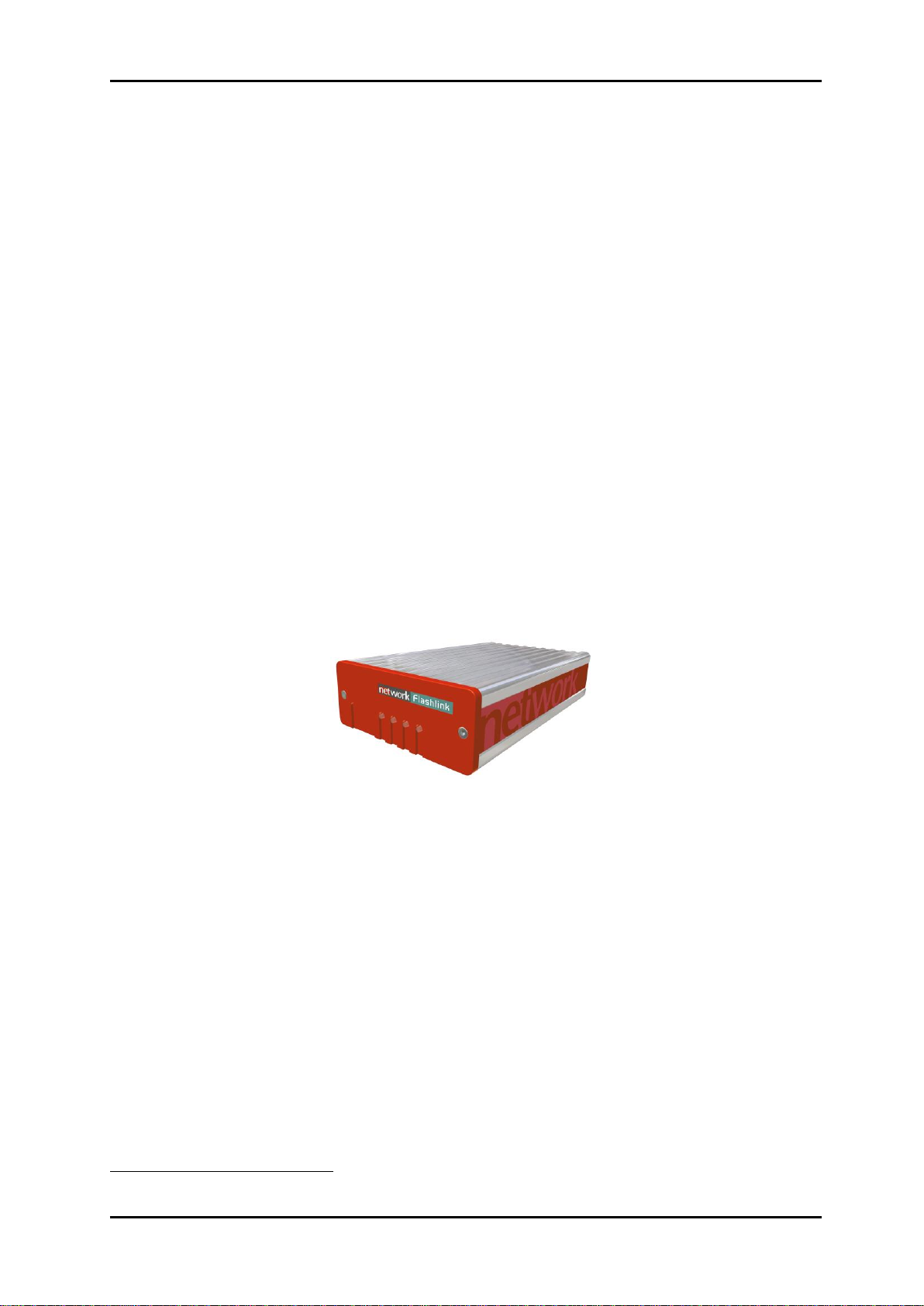
1 Product overview
The N-BOX is meant to meet the need for a one module desktop box for Flashlink module
cards. This box shall use the same backplane as in the standard 2RU frame. This means
that the modules and backplanes can be removed from a desktop box and replaced into the
FR-2RU-10-2 frame. In addition, 4 desktop boxes can be assembled together into a 1 RU
box holder and function as a 1 RU unit.
Please note the power constraint on older N-BOXs described in chapter 2.2.
nevion.com | 4
Page 5
N-BOX Rev. E
AC Power:
External power supplies 100 - 260 VAC
DC Power:
±15V, connector DB9 male
Dimensions:
109 x 43 x 198 mm.
Card slots:
1.
Internal voltages:
+5V, -5V, +15V, -15V.
1
2 Specifications
2.1 General specifications
2.2 Power constraints
There is a power constraint of 4W on N-BOXs delivered before 2008-09-01. This constraint
has been removed for N-BOXs delivered after this date. This constraint causes some newer
cards such as DWC-HD, ARC-SD, UDC-HD-XMUX and other power demanding cards to not
function properly.
The two types of N-BOXs can be distinguished when looking at the power module on the
back without having connected any Flashlink backplane into the N-BOX. N-BOXs produced
before 2008-09-01 have the number 4052966 printed in the silk screen next to the 16 pin
Flashlink connector. A newer N-BOX has no such marking.
2.3 Front view
The front view of the N-BOX shows status LEDs for the module that is included in the NBOX.
Figure1: LEDs in from of the N-BOX
The leftmost1 LED of each module card is a "general status" LED.
Green light means that the card is OK.
Red light means that the card is faulty.
No light means that the power is not switched on.
The meaning of each LED on the module cards is described in their respective manuals.
LEDs from left to right when box is viewed as in this figure.
nevion.com | 5
Page 6

N-BOX Rev. E
2.4 Rear view
Figure 2 shows an example of an N-BOX seen from the rear side. To the left is the connector
module for the power supply delivered with the N-BOX. The other connector modules are
described in their respective user manuals
Figure 2: Rear view of an N-BOX
nevion.com | 6
Page 7

N-BOX Rev. E
3 Configuration
3.1 Address setting on each N-BOX
Each N-BOX can be assigned an address through the address selector on the underside of
the box. Maximum 8 addresses are available. This address setting only applies when your
application includes more than one N-BOX. The addresses represent card positions in a FR2RU-10-2 frame, and are numbered from 0 – 9. Default address/card position is 0.
nevion.com | 7
Page 8

N-BOX Rev. E
Pin #1
0V / GND
Pin #2
+5V
Reserved.
Pin #3
Tx(+)
Output from module.
Pin #4
+15V
DC Input.
Pin #5
Rx(-)
Output from module.
Pin #6
Rx(+)
Output from module.
Pin #7
Tx(-)
Output from module.
Pin #8
-15V
DC Input.
Pin #9
0V / GND
4 Connections
4.1 Power connection
DC: Connect the DB9 connector from the external DC power supply to the DB9 male
connector of the N-BOX. Tighten the screws to ensure a proper contact.
4.1.1 Pin-out DC input
The maximum current drawn from each pin of the DB9 connector is 2,5A.
4.2 Module connections
The other connectors are module specific; hence they are described in their respective user
manuals.
nevion.com | 8
Page 9

N-BOX Rev. E
5 N-BOX operation
In order to reconfigure an N-BOX, the front panel must be removed. Each module has a
corresponding connector module at the rear, and is hot swappable.
Use safety goggles when hot-swapping module cards.
If a receiver card is removed from the N-BOX, an invisible laser beam may be
emitted inside the N-BOX from the laser at the other end. The laser beam might
be harmful to your eyes.
5.1 Removing the front panel
Detach the front panel by unfastening the two screws fixing the front panel. Use a TX-08
screwdriver for this. A TX-08 screwdriver is included in the shipment of your N-BOX.
Figure 3: Removing the front panel
5.2 Card removal
To remove a module card from the N-BOX frame, release the card by moving the red handle
until it is in horizontal position. Then pull the card out of the N-BOX with the red handle. After
removing a card, it is important that the protective cap is put back on the ferrule tip.
When removing a receiver card from the N-BOX (hot swapping), the laser beam
may be present inside the N-BOX (transmitted through the fiber). To avoid
damaging your eyes, never look directly into the N-BOX unless you are 100 %
sure that no laser beam is present inside the N-BOX.
5.3 Back plane insertion
You must install the accompanying back plane card before you can insert a new module card
into the frame. Turn off the power by disconnecting the DB9 power contact to the N-BOX.
Remove the module card from the box, according to the procedure in Chapter Error!
Reference source not found.. Please follow anti-static procedures when handling circuit
boards with active components.
Remove all 4 screws from the back plane to be replaced. Remove the back plane by lifting it
straight out from the rear of the frame. Insert the new back plane and tighten the screws.
nevion.com | 9
Page 10

N-BOX Rev. E
Figure 4: Removing/inserting back plane
5.4 Card insertion
After the front panel is removed, full access to the card modules inside the N-BOX is given.
The N-BOX is equipped with guide rails to align the module card into its position.
nevion.com | 10
Page 11

N-BOX Rev. E
6 N-BOX configuration examples
6.1 N-BOX in a 1RU frame
It is possible to mount up to four flashlink® N-BOX modules into a 19” 1RU frame, as shown
below.
Figur 5: N-BOX in a 1RU frame
Please contact Nevion Europe AS for further information about the mounting kits.
6.2 N-BOX mounting brackets
ETH-CON modules may also be mounted against walls, under desks, etc. The figure below
shows available mounting plates for ETH-CON.
Figur 6: Mounting plates for the N-BOX
The following examples show how to apply the available mounting kits.
nevion.com | 11
Page 12

N-BOX Rev. E
Figur 7: Wall - Under desk – Wall
Figur 8: Between wall/desk - Wall - Under desk
Figur 9: Wall - Under desk
Please contact Nevion Europe AS for further information about the mounting kits.
nevion.com | 12
Page 13

N-BOX Rev. E
Product Warranty
The warranty terms and conditions for the product(s) covered by this manual follow the
General Sales Conditions by Nevion, which are available on the company web site:
www.nevion.com
nevion.com | 13
Page 14

N-BOX Rev. E
組成名稱
Part Name
Toxic or hazardous substances and elements
鉛
Lead
(Pb)
汞
Mercury
(Hg)
镉
Cadmium
(Cd)
六价铬
Hexavalent
Chromium
(Cr(VI))
多溴联苯
Polybrominated
biphenyls
(PBB)
多溴二苯醚
Polybrominated
diphenyl ethers
(PBDE)
N-BOX O O O O O O
O: Indicates that this toxic or hazardous substance contained in all of the homogeneous materials for
this part is below the limit requirement in SJ/T11363-2006.
X: Indicates that this toxic or hazardous substance contained in at least one of the homogeneous
materials used for this part is above the limit requirement in SJ/T11363-2006.
Appendix A Materials declaration and recycling information
A.1 Materials declaration
For product sold into China after 1st March 2007, we comply with the “Administrative
Measure on the Control of Pollution by Electronic Information Products”. In the first stage of
this legislation, content of six hazardous materials has to be declared. The table below
shows the required information.
This is indicated by the product marking:
A.2 Recycling information
Nevion provides assistance to customers and recyclers through our web site
http://www.nevion.com/. Please contact Nevion’s Customer Support for assistance with
recycling if this site does not show the information you require.
Where it is not possible to return the product to Nevion or its agents for recycling, the
following general information may be of assistance:
Before attempting disassembly, ensure the product is completely disconnected from
power and signal connections.
All major parts are marked or labeled to show their material content.
Depending on the date of manufacture, this product may contain lead in solder.
Some circuit boards may contain battery-backed memory devices.
nevion.com | 14
 Loading...